

Page 1
Operating instructions
Betriebsanleitung
Mode d'emploi
Manual de instrucciones
Gas cylinder scale model GCS-1
Gasaschenwaage Typ GCS-1
Balance pour bouteilles de gaz type GCS-1
Balanza de bombonas de gas GCS-1
GB
D
F
E
Gas cylinder scale model GCS-1
Page 2

GB
Operating instructions model GCS-1 Page 3 - 24
D
Betriebsanleitung Typ
F
Mode d'emploi type GCS-1 Page 45 - 60
E
Manual de instrucciones modelo GCS-1 Página 61 - 75
© 2011 WIKA Alexander Wiegand SE & Co. KG
All rights reserved. / Alle Rechte vorbehalten.
®
WIKA
is a registered trademark in various countries.
®
WIKA
ist eine geschützte Marke in verschiedenen Ländern.
Vor Beginn aller Arbeiten Betriebsanleitung lesen!
Zum späteren Gebrauch aufbewahren!
GCS-1
Seite 25 - 44
Prior to starting any work, read the operating instructions!
Keep for later use!
Vor Beginn aller Arbeiten Betriebsanleitung lesen!
Zum späteren Gebrauch aufbewahren!
Lire le mode d‘emploi avant de commencer toute opération !
A conserver pour une utilisation ultérieure !
¡Leer el manual de instrucciones antes de comenzar cualquier trabajo!
¡Guardar el manual para una eventual consulta!
2 WIKA operating instructions gas cylinder scale model GCS-1
11145676.05 11/2011 GB/D/F/E
Page 3

Contents
Contents
1. General information 4
2. Safety 6
3. Specications 9
4. Design and function 13
5. Transport, packaging and storage 13
6. Commissioning, operation 14
7. Adjustment of zero point / span 15
8. Maintenance and cleaning 16
9. Faults 17
GB
10. Return and disposal 17
Appendix 1: EC declaration of conformity 18
Appendix 2: Declaration of conformity ATEX 19
Declarations of conformity can be found online at www.wika.com.
11145676.05 11/2011 GB/D/F/E
3WIKA operating instructions gas cylinder scale model GCS-1
Page 4

1. General information
1. General information
■
The gas cylinder scale described in the operating instructions has been designed
and manufactured using state-of-the-art technology. All components are subject
GB
to stringent quality and environmental criteria during production. Our management
systems are certied to ISO 9001 and ISO 14001.
■
These operating instructions contain important information on handling the instrument. Working safely requires that all safety instructions and work instructions are
observed.
■
Observe the relevant local accident prevention regulations and general safety regulations for the instrument's range of use.
■
The operating instructions are part of the product and must be kept in the immediate
vicinity of the instrument and readily accessible to skilled personnel at any time.
■
Skilled personnel must have carefully read and understood the operating instructions
prior to beginning any work.
■
The manufacturer's liability is void in the case of any damage caused by using the
product contrary to its designated use, non-compliance with these operating instructions, assignment of insuciently qualied skilled personnel or unauthorised modications to the instrument.
■
The general terms and conditions contained in the sales documentation shall apply.
■
Subject to technical modications.
■
Further information:
- Internet address: www.wika.com
- Relevant data sheet: PE 87.19
- Application consultant: Tel.: (+49) 9372/132-8976
Fax: (+49) 9372/132-8008976
E-mail: support-tronic@wika.de
4 WIKA operating instructions gas cylinder scale model GCS-1
11145676.05 11/2011 GB/D/F/E
Page 5

1. General information
Explanation of symbols
WARNING!
... indicates a potentially dangerous situation that can result in serious
injury or death, if not avoided.
CAUTION!
... indicates a potentially dangerous situation that can result in light
injuries or damage to equipment or the environment, if not avoided.
Information
… points out useful tips, recommendations and information for ecient
and trouble-free operation.
WARNING!
... indicates a potentially dangerous situation in the hazardous area that
can result in serious injury or death, if not avoided.
Abbreviations
2-wire
U+ Positive power terminal
U- Negative power terminal
S+ Positive measurement terminal
S - Negative measurement terminal
Two connection lines are used for the voltage supply.
The measurement signal also provides the supply current.
GB
11145676.05 11/2011 GB/D/F/E
5WIKA operating instructions gas cylinder scale model GCS-1
Page 6
2. Safety
2. Safety
WARNING!
Before installation, commissioning and operation, ensure that the appro-
GB
2.1 Intended use
The gas cylinder scale is used to measure mass.
The instrument has been designed and built solely for the intended use described here,
and may only be used accordingly.
The manufacturer shall not be liable for claims of any type based on operation contrary
to the intended use.
priate gas cylinder scale has been selected in terms of measuring range,
design and specic measuring conditions.
Non-observance can result in serious injury and/or damage to the equipment.
Further important safety instructions can be found in the individual
chapters of these operating instructions.
2.2 Personnel qualication
WARNING!
Risk of injury should qualication be insucient!
Improper handling can result in considerable injury and damage to
equipment.
■
The activities described in these operating instructions may only be
carried out by skilled personnel who have the qualications described
below.
■
Keep unqualied personnel away from hazardous areas.
Skilled personnel
Skilled personnel are understood to be personnel who, based on their technical training,
knowledge of measurement and control technology and on their experience and
knowledge of country-specic regulations, current standards and directives, are capable
of carrying out the work described and independently recognising potential hazards.
Special operating conditions require further appropriate knowledge, e.g. of aggressive
media.
6 WIKA operating instructions gas cylinder scale model GCS-1
11145676.05 11/2011 GB/D/F/E
Page 7

2. Safety
2.3 Additional safety instructions for gas cylinder scale per ATEX
WARNING!
■
Non-observance of these instructions and their contents may result in
the loss of explosion protection.
■
For operation in hazardous areas, the lower voltage levels apply, as
per chapter "3. Specications".
■
Actions or alterations to the gas cylinder scale, which are not described in these
operating instructions, are not permitted.
■
If faults cannot be eliminated, the instrument must be taken out of operation and
prevented from being accidentally put back into service.
■
Always operate the instrument within its overload limits.
■
Observe the working conditions in accordance with chapter "3. Specications".
■
The cable shield should be earthed at one end, and preferably in the non-hazardous
area (EN 60079-14). For instruments with a cable outlet, the cable shield is
connected to the case. Additional connection of the shield is then only permitted if
any accidental energisation between the shield connection (e.g. at the power supply)
and the case can be avoided (see EN 60079-14).
GB
■
Power the GCS-1-A gas cylinder scale variant, with marking "Ex nL IIC T4", by an
energy-limited 4 ... 20 mA current loop.
■
Connect the gas cylinder scale with marking "Ex nA IIC T4" to a power and signal
circuit with transient protection in accordance with EN 60079-15, chapter 23 C.
■
Disconnect a gas cylinder scale with the marking Ex nA, or when it is operated under
nA conditions, only after the power has been turned o.
■
Both the internal capacitance and inductance must be considered
■
Flying leads with bare ends must be nished with ferrule ends (cable preparation)
■
Provide equipotential bonding between the earth at the voltage supply and the gas
cylinder and/or the installation, in case they are connected conductively.
11145676.05 11/2011 GB/D/F/E
7WIKA operating instructions gas cylinder scale model GCS-1
Page 8

2. Safety
2.4 Special hazards
WARNING!
Observe the information given in the applicable type examination
GB
2.6 Labelling / safety marks
certicate and the relevant country-specic regulations for installation
and use in explosive atmospheres (e.g. IEC 60079-14, NEC, CEC).
Non-observance can result in serious injury and/or damage to equipment.
For additional important safety instructions for instruments with ATEX
approval see chapter "2.3 Additional safety instructions for gas cylinder
scale per ATEX".
WARNING!
For hazardous media such as oxygen, acetylene, ammable or toxic
gases or liquids, and refrigeration plants, compressors, etc., in addition
to all standard regulations, the appropriate existing codes or regulations
must also be followed.
WARNING!
Residual media in dismounted instruments can result in a risk to persons,
the environment and equipment.
Take sucient precautionary measures.
Product label
Output signal
Power supply
P# Product no.
S# Serial no.
8 WIKA operating instructions gas cylinder scale model GCS-1
Measuring range
Pin assignment
Date of manufacture
11145676.05 11/2011 GB/D/F/E
Page 9

2. Safety / 3. Specications
Explanation of symbols
Before mounting and commissioning the instrument, ensure
you read the operating instructions!
CE, Communauté Européenne
Instruments bearing this mark comply with the relevant European directives.
ATEX European Explosion Protection Directive
(Atmosphère = AT, explosible = Ex)
Instruments bearing this mark comply with the requirements of the
European Directive 94/9/EC (ATEX) on explosion protection.
3. Specications
3.1 Measuring ranges
Weight
lbs
kg
Measuring range 0 ... 60 0 ... 100 0 ... 300
Overload 0 ... 250 0 ... 300 0 ... 750
Measuring range 0 ... 27.2 0 ... 45.4 0 ... 136.1
Overload 0 ... 115 0 ... 130 0 ... 340
GB
Other measuring ranges on request.
3.2 Output signal
Model Signal
GCS-1-A (2-wire) 4 ... 20 mA
GCS-1-G (4-wire) DC 0 ... 5 V
GCS-1-F (4-wire) DC 0 ... 10 V
Load
Model GCS-1-A: ≤ (power supply - 10 V) / 0.02 A
Model GCS-1-G: > 5 kΩ
Model GCS-1-F: > 10 kΩ
11145676.05 11/2011 GB/D/F/E
9WIKA operating instructions gas cylinder scale model GCS-1
Page 10

3. Specications
3.3 Voltage supply
Power supply
DC 14 ... 30 V
GB
Maximum output current
≤ 35 mA
3.4 Accuracy
Analogue signal
≤ 0.1 % of span
≤ 0.05 % of span (BFSL)
Non-linearity (IEC 61298-2)
≤ 0.05 % of span
Long-term stability (per month)
≤ 0.04 % of span (at reference conditions)
Adjustability of zero point / span
± 5 % through built-in potentiometer
Temperature eect
Temperature coecients in rated temperature range
■
Mean TC zero point: ≤ ± 0.1 % of span / 10 K
■
Mean TC span: ≤ ± 0.1 % of span / 10 K
3.5 Reference conditions (per IEC 61298-1)
Temperature: 15 ... 25 °C
Atmospheric pressure: 950 ... 1050 mbar
Humidity: 45 ... 75 % relative
Nominal position: horizontal
Power supply: DC 24 V
Load: see output signals
10 WIKA operating instructions gas cylinder scale model GCS-1
11145676.05 11/2011 GB/D/F/E
Page 11

3. Specications
3.6 Operating conditions
Mechanics
Resistant to impact of 90 kg from a height of 10 cm
Ingress protection: IP 65 (IEC 60529)
Permissible temperatures
Ambient temperature
■
T4: -20 ... +50 °C
■
T5: -20 ... +40 °C
Storage temperature: -20 ... +60 °C
Rated temperature range: -10 ... +50 °C
3.7 Materials
Sensor
Aluminium
Case
Stainless steel
Base plate
Stainless steel
GB
3.8 Approvals, directives and certicates
CE conformity
EMC directive:
2004/108/EC
EN 61326 emission (group 1, class B)
and interference immunity (industrial application)
Explosion protection
Directive Ignition protection type
Without ATEX approval ATEX category 3G Ex nL IIC T4, T5 X
ATEX category 3G Ex nA IIC T4, T5 X
11145676.05 11/2011 GB/D/F/E
11WIKA operating instructions gas cylinder scale model GCS-1
Page 12
3. Specications
3.9 Safety-related maximum values
(only valid for devices to ATEX category 3G)
Model GCS-1-A Ex nL IIC T4, T5 X Ex nA IIC T4, T5 X
GB
Supply voltage: DC 14 ... 24 V DC 14 ... 24 V
Current limitation Ii: 30 mA Power limitation P
Internal capacitance C
Internal inductance L
i:
i:
i:
Model GCS-1-G Ex nL IIC T4, T5 X Ex nA IIC T4, T5 X
Supply voltage: DC 14 ... 24 V DC 14 ... 24 V
Current limitation Ii: 30 mA Power limitation P
Internal capacitance C
Internal inductance L
Max. output voltage U
Max. output current I
External capacitance C
External inductance L
i:
i:
i:
o:
o:
o:
o:
Model GCS-1-F Ex nL IIC T4, T5 X Ex nA IIC T4, T5 X
Supply voltage: DC 14 ... 24 V DC 14 ... 24 V
Current limitation Ii: 30 mA Power limitation P
Internal capacitance C
Internal inductance L
Max. output voltage U
Max. output current I
External capacitance C
External inductance L
1) 56 pF / cable length in m
2) 0.1 µH / cable length in m
i:
i:
i:
o:
o:
o:
o:
1 W 1 W
1)
0,1 µF
2)
1,2 mH
1 W 1 W
1)
0,1 µF
2)
1,2 mH
DC 12 V 35 mA 4,122 µF 23,4 mH -
1 W 1 W
1)
0,1 µF
2)
1,2 mH
DC 12 V 35 mA 4,122 µF 23,4 mH -
-
-
-
-
-
-
12 WIKA operating instructions gas cylinder scale model GCS-1
11145676.05 11/2011 GB/D/F/E
Page 13

3. Specications ... 5. Transport, packaging and storage
7.3 Electrical connection
Type of connection: Cable outlet
Cable length: 6 m (≈ 20 ft)
Electrical safety
Short-circuit resistance: S+ vs. UReverse polarity protection: U+ vs. UInsulation voltage: DC 500 V
4. Design and function
4.1 Short description / Description
With the gas cylinder scale, the mass of the gas cylinder and its contents is measured
and converted to an electrical signal. This electrical signal varies in proportion to the mass
and can be evaluated accordingly.
4.2 Scope of delivery
■
Gas cylinder scale with 6 m cable outlet
■
Protocol
Cross-check scope of delivery with the delivery note.
GB
5. Transport, packaging and storage
5.1 Transport
Check the gas cylinder scale for any damage that may have been caused during transportation.
Obvious damage must be reported immediately.
5.2 Packaging
Do not remove packaging until just before mounting.
Keep the packaging as it will provide optimum protection during transport (e.g. change in
installation site, sending for repair).
5.3 Storage
Permissible conditions at the place of storage:
Storage temperature: -20 ... 60 °C
WARNING!
Before storing the instrument (following operation), remove any residual
media. This is of particular importance if the medium is hazardous to health,
e.g. caustic, toxic, carcinogenic, radioactive, etc.
11145676.05 11/2011 GB/D/F/E
13WIKA operating instructions gas cylinder scale model GCS-1
Page 14
6. Commissioning, operation
6. Commissioning, operation
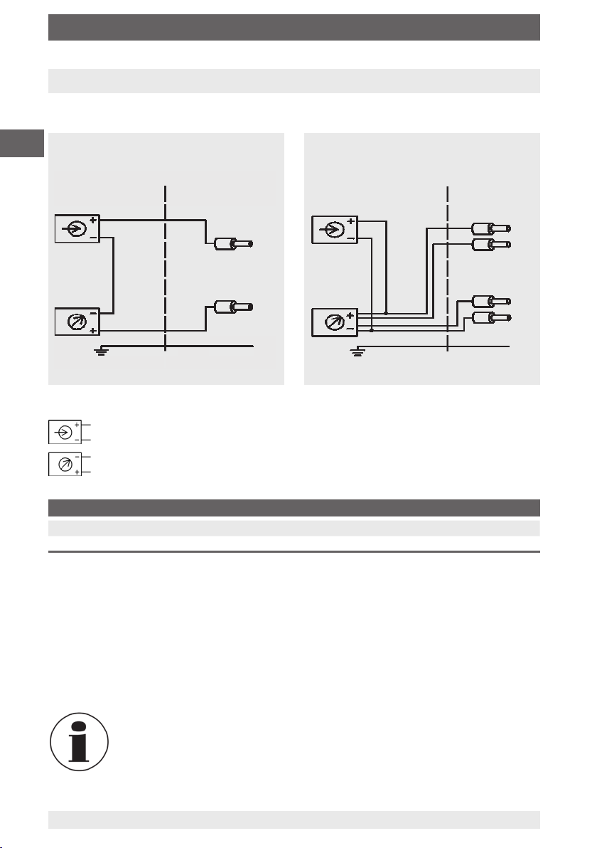
Electrical connection
2-wire
GB
Not Ex area Ex area
Shield
(connected to case)
Legend
Load
(e.g. digital indicator)
Voltage source
Pin assignment
2-wire U+ / S+ = brown U-/ S- =black
4-wire U
= red U- = black S+ = orange S- = brown
+
Brown
Black
4-wire
Not Ex area Ex area
Red
Orange
Brown
Black
Shield
(connected to case)
The shield is connected to the case.
Ensure that no moisture can enter at the cable end.
Functional check
The output signal must be proportional to the mass. If this is not the case, this may
indicate a damaged measuring cell. In this case, see chapter "9. Faults".
When weighing a gas cylinder make sure that the gas cylinder scale is
seated on a solid and level base and that it cannot catch on any other
objects.
14 WIKA operating instructions gas cylinder scale model GCS-1
11145676.05 11/2011 GB/D/F/E
Page 15

7. Adjustment of zero point / span
7. Adjustment of zero point / span
Preparation
■
In order to access the zero point and span potentiometers, unscrew the protective
cap using a screwdriver (see gure A).
■
Introduce a reference mass which is at least 3 x as accurate as the given accuracy.
Zero point
■
Remove the load from the gas cylinder scale.
■
By adjusting the signal to 4 mA, the zero point can be set (see gure B).
Span
■
Set the span by loading the scale with the appropriate reference mass and adjusting
the signal to 20 mA.
■
Check the zero point.
■
If the zero point is not right, repeat the procedure.
■
Screw the sealing cap with seal back in, in order to close the potentiometer entry.
A
GB
B
After the adjustment, check that the system is functioning correctly.
Recommended recalibration cycle: 1 year
11145676.05 11/2011 GB/D/F/E
15WIKA operating instructions gas cylinder scale model GCS-1
Page 16

8. Maintenance and cleaning / 9. Faults
8. Maintenance and cleaning
8.1 Maintenance
The gas cylinder scale is maitenance-free.
GB
Repairs must only be carried out by the manufacturer.
8.2 Cleaning
CAUTION!
■
Electrical connections must not come into contact with moisture.
■
Wash or clean the dismounted instrument before returning it, in order
to protect persons and the environment from exposure to residual
media.
For information on returning the instrument see chapter "10.1 Return".
9. Faults
Problem Causes Measure
No output signal No power supply
Cable break
Wiring reversed
Scales platform blocked
Gas cylinder scale defective
due to incorrect power supply or
current pulse
Constant output signal upon
change in weight
Signal too low Power supply too low
Zero point signal too low or too
high
Signal characteristic non-linear Mechanical overload Replace the gas cylinder scale
Scales platform blocked
Mechanical overload
Gas cylinder scale defective
due to incorrect power supply or
current pulse
Load too high
Mechanical overload
Mechanical overload Recalibrate the gas cylinder scale
Check voltage supply
Check the through drilling
Rectify polarity
Check the scale is free-standing
Replace the gas cylinder scale
Check the scale is free-standing
Replace the gas cylinder scale
Replace the gas cylinder scale
Check the power supply
Rectify the load and/or power
supply
Recalibrate the gas cylinder scale
Replace the gas cylinder scale
Replace the gas cylinder scale
16 WIKA operating instructions gas cylinder scale model GCS-1
11145676.05 11/2011 GB/D/F/E
Page 17
9. Faults / 10. Return, disposal
CAUTION!
If faults cannot be eliminated by means of the measures listed above,
the gas cylinder scale must be shut down immediately, and it must
be ensured that signal is no longer present, and it must be prevented
from being inadvertently put back into service. In this case, contact the
manufacturer.
If a return is needed, please follow the instructions given in chapter "10.1
Return".
10. Return and disposal
WARNING!
Residual media in dismounted gas cylinder scales can result in a risk to
persons, the environment and equipment.
Take sucient precautionary measures.
10.1 Return
WARNING!
Strictly observe the following when shipping the instrument:
All instruments delivered to WIKA must be free from any kind of
hazardous substances (acids, leachate, solutions, etc.).
GB
When returning the instrument, use the original packaging or a suitable transport
package.
Enclose the completed returns form with the instrument.
The return form ist available in the 'Service' section on www.wila.com
10.2 Disposal
Incorrect disposal can put the environment at risk.
Dispose of instrument components and packaging materials in an environmentally
compatible way and in accordance with the country-specic waste disposal regulations.
11145676.05 11/2011 GB/D/F/E
17WIKA operating instructions gas cylinder scale model GCS-1
Page 18

Appendix 1: EC declaration of conformity
GB
18 WIKA operating instructions gas cylinder scale model GCS-1
11145676.05 11/2011 GB/D/F/E
Page 19

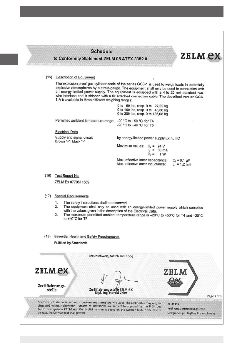
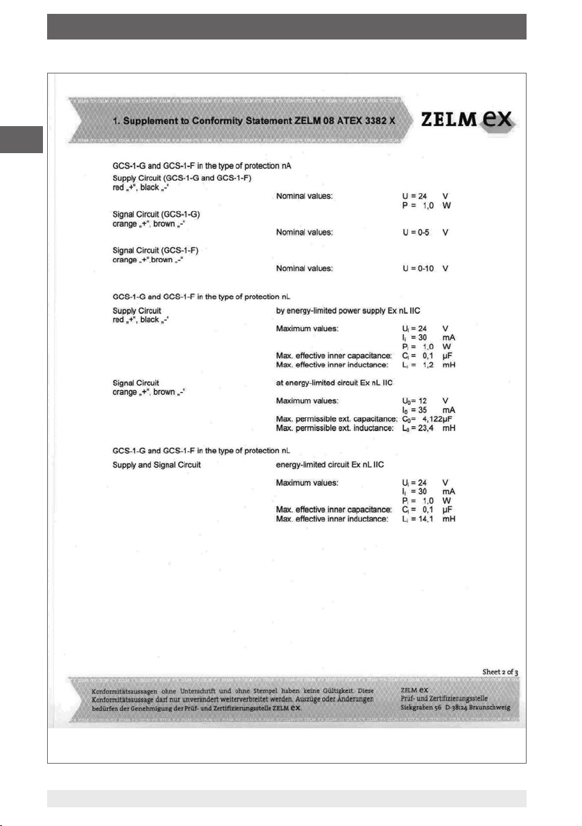
Appendix 2: Declaration of conformity ATEX
GB
11145676.05 11/2011 GB/D/F/E
19WIKA operating instructions gas cylinder scale model GCS-1
Page 20
Appendix 2: Declaration of conformity ATEX
GB
20 WIKA operating instructions gas cylinder scale model GCS-1
11145676.05 11/2011 GB/D/F/E
Page 21

Appendix 2: Declaration of conformity ATEX
GB
11145676.05 11/2011 GB/D/F/E
21WIKA operating instructions gas cylinder scale model GCS-1
Page 22
Appendix 2: Declaration of conformity ATEX
GB
22 WIKA operating instructions gas cylinder scale model GCS-1
11145676.05 11/2011 GB/D/F/E
Page 23

Appendix 2: Declaration of conformity ATEX
GB
11145676.05 11/2011 GB/D/F/E
23WIKA operating instructions gas cylinder scale model GCS-1
Page 24

GB
24 WIKA operating instructions gas cylinder scale model GCS-1
11145676.05 11/2011 GB/D/F/E
Page 25

Inhalt
Inhalt
1. Allgemeines 26
2. Sicherheit 28
3. Technische Daten 31
4. Aufbau und Funktion 35
5. Transport, Verpackung und Lagerung 35
6. Inbetriebnahme, Betrieb 36
7. Einstellung Nullpunkt / Spanne 37
8. Wartung und Reinigung 38
9. Störungen 39
10. Rücksendung und Entsorgung 39
Anlage 1: EG-Konformitätserklärung 18
Anlage 2: Konformitätserklärung ATEX 40
Konformitätserklärungen nden Sie online unter www.wika.de.
D
11145676.05 11/2011 GB/D/F/E
25WIKA Betriebsanleitung Gasaschenwaage Typ GCS-1
Page 26

1. Allgemeines
1. Allgemeines
■
Die in der Betriebsanleitung beschriebene Gasaschenwaage wird nach den neuesten Erkenntnissen konstruiert und gefertigt.
Alle Komponenten unterliegen während der Fertigung strengen Qualitäts- und
Umweltkriterien. Unsere Managementsysteme sind nach ISO 9001 und ISO 14001
zertiziert.
D
■
Diese Betriebsanleitung gibt wichtige Hinweise zum Umgang mit dem Gerät. Voraussetzung für sicheres Arbeiten ist die Einhaltung aller angegebenen Sicherheitshinweise und Handlungsanweisungen.
■
Die für den Einsatzbereich des Gerät geltenden örtlichen Unfallverhütungsvorschriften und allgemeinen Sicherheitsbestimmungen einhalten.
■
Die Betriebsanleitung ist Produktbestandteil und muss in unmittelbarer Nähe des
Gerätes für das Fachpersonal jederzeit zugänglich aufbewahrt werden.
■
Das Fachpersonal muss die Betriebsanleitung vor Beginn aller Arbeiten sorgfältig
durchgelesen und verstanden haben.
■
Die Haftung des Herstellers erlischt bei Schäden durch bestimmungswidrige Verwendung, Nichtbeachten dieser Betriebsanleitung, Einsatz ungenügend qualizierten
Fachpersonals sowie eigenmächtiger Veränderung am Gerät.
■
Es gelten die allgemeinen Geschäftsbedingungen in den Verkaufsunterlagen.
■
Technische Änderungen vorbehalten.
■
Weitere Informationen:
- Internet-Adresse: www.wika.de
- zugehöriges Datenblatt: PE 87.19
- Anwendungsberater: Tel.: (+49) 9372/132-8976
Fax: (+49) 9372/132-8008976
E-Mail: support-tronic@wika.de
26 WIKA Betriebsanleitung Gasaschenwaage Typ GCS-1
11145676.05 11/2011 GB/D/F/E
Page 27

1. Allgemeines
Symbolerklärung
WARNUNG!
… weist auf eine möglicherweise gefährliche Situation hin, die zum Tod
oder zu schweren Verletzungen führen kann, wenn sie nicht gemieden
wird.
VORSICHT!
… weist auf eine möglicherweise gefährliche Situation hin, die
zu geringfügigen oder leichten Verletzungen bzw. Sach- und
Umweltschäden führen kann, wenn sie nicht gemieden wird.
Information
… hebt nützliche Tipps und Empfehlungen sowie Informationen für einen
ezienten und störungsfreien Betrieb hervor.
WARNUNG!
… weist auf eine möglicherweise gefährliche Situation im
explosionsgefährdeten Bereich hin, die zum Tod oder zu schweren
Verletzungen führen kann, wenn sie nicht gemieden wird.
D
Abkürzungen
2-Leiter
U
+
U- Negativer Versorgungsanschluss
S
+
S - Negativer Messanschluss
11145676.05 11/2011 GB/D/F/E
Zwei Anschlussleitungen dienen zur Spannungsversorgung.
Der Speisestrom ist das Messsignal
Positiver Versorgungsanschluss
Positiver Messanschluss
27WIKA Betriebsanleitung Gasaschenwaage Typ GCS-1
Page 28

2. Sicherheit
2. Sicherheit
WARNUNG!
Vor Montage, Inbetriebnahme und Betrieb sicherstellen, dass die richtige
Gasaschenwaage hinsichtlich Messbereich, Ausführung und spezischen Messbedingungen ausgewählt wurde.
D
2.1 Bestimmungsgemäße Verwendung
Die Gasaschenwaage dient zum Messen von Masse.
Das Gerät ist ausschließlich für den hier beschriebenen bestimmungsgemäßen
Verwendungszweck konzipiert und konstruiert und darf nur dementsprechend
verwendet werden.
Ansprüche jeglicher Art aufgrund von nicht bestimmungsgemäßer Verwendung sind
ausgeschlossen.
Bei Nichtbeachten können schwere Körperverletzungen und/oder
Sachschäden auftreten.
Weitere wichtige Sicherheitshinweise benden sich in den einzelnen
Kapiteln dieser Betriebsanleitung.
2.2 Personalqualikation
WARNUNG!
Verletzungsgefahr bei unzureichender Qualikation!
Unsachgemäßer Umgang kann zu erheblichen Personen- und
Sachschäden führen.
■
Die in dieser Betriebsanleitung beschriebenen Tätigkeiten nur durch
Fachpersonal nachfolgend beschriebener Qualikation durchführen
lassen.
■
Unqualiziertes Personal von den Gefahrenbereichen fernhalten.
Fachpersonal
Das Fachpersonal ist aufgrund seiner fachlichen Ausbildung, seiner Kenntnisse
der Mess- und Regelungstechnik und seiner Erfahrungen sowie Kenntnis der
landesspezischen Vorschriften, geltenden Normen und Richtlinien in der Lage,
die beschriebenen Arbeiten auszuführen und mögliche Gefahren selbstständig zu
erkennen.
Spezielle Einsatzbedingungen verlangen weiteres entsprechendes Wissen, z. B. über
aggressive Medien.
28 WIKA Betriebsanleitung Gasaschenwaage Typ GCS-1
11145676.05 11/2011 GB/D/F/E
Page 29

2. Sicherheit
2.3 Zusätzliche Sicherheitshinweise für Gasaschenwaage nach ATEX
WARNUNG!
■
Die Nichtbeachtung dieser Inhalte und Anweisungen kann zum Verlust
des Explosionsschutzes führen.
■
Beim Betrieb im Ex-Bereich gelten die geringeren Spannungspegel
gemäß Kapitel „3. Technische Daten“.
■
Eingrie und Änderungen an der Gasaschenwaage, welche nicht in dieser
Betriebsanleitung beschrieben werden, sind unzulässig.
■
Falls Störungen nicht beseitigt werden können, ist die Gasaschenwaage außer
Betrieb zu setzen und gegen versehentliche Inbetriebnahme zu schützen.
■
Die Gasaschenwaage immer innerhalb des Überlastgrenzbereiches betreiben.
■
Die Betriebsparameter gemäß Kapitel „3.Technische Daten“ beachten.
■
Den Kabelschirm einseitig und bevorzugt im sicheren Nicht-Ex-Bereich
(EN 60079-14) erden. Bei Geräten mit Kabelausgang ist der Schirm mit dem
Gehäuse verbunden. Ein zusätzlicher Anschluss des Schirms ist nur dann zulässig,
wenn eine Potentialverschleppung zwischen Schirmanschluss (z. B. am Speisegerät)
und Gehäuse vermieden werden kann (siehe EN 60079-14).
D
■
Die Gasaschenwaage Variante GCS-1-A mit Kennzeichnung „Ex nL IIC T4“ aus
einer energiebegrenzten 4 ... 20 mA Stromschleife versorgen.
■
Die Gasaschenwaage mit Kennzeichnung „Ex nA IIC T4“ an einen Versorgungsund Signalstromkreis mit Schutz vor Transienten gemäß EN 60079-15 Abschnitt 23 C
anschließen.
■
Gasaschenwaage mit Kennzeichnung Ex nA, oder wenn diese unter
nA-Bedingungen betrieben wird, nicht unter Spannung trennen.
■
Die innere wirksame Kapazität und Induktivität beachten.
■
Feindrahtige Leiterenden mit Aderendhülsen versehen (Kabelkonfektionierung).
■
Für einen Potentialausgleich zwischen der Erde an der Spannungsversorgung und
der Gasasche bzw. der Installation sorgen, falls diese leitend verbunden ist.
11145676.05 11/2011 GB/D/F/E
29WIKA Betriebsanleitung Gasaschenwaage Typ GCS-1
Page 30

2. Sicherheit
2.4 Besondere Gefahren
WARNUNG!
Die Angaben der geltenden Baumusterprüfbescheinigung sowie die
jeweiligen landesspezischen Vorschriften zur Installation und Einsatz
in explosionsgefährdeten Bereichen (z. B. IEC 60079-14, NEC, CEC)
D
einhalten. Bei Nichtbeachten können schwere Körperverletzungen
und/oder Sachschäden auftreten.
Weitere wichtige Sicherheitshinweise für Geräte nach ATEX siehe Kapitel
„2.3 Zusätzliche Sicherheitshinweise für Gasaschenwaage nach ATEX“.
WARNUNG!
Bei gefährlichen Messstoen wie z. B. Sauersto, Acetylen, brennbaren
oder giftigen Stoen, sowie bei Kälteanlagen, Kompressoren etc.
müssen über die gesamten allgemeinen Regeln hinaus die einschlägigen
Vorschriften beachtet werden.
WARNUNG!
Messstoreste in ausgebauten Gasaschenwaagen können zur
Gefährdung von Personen, Umwelt und Einrichtung führen.
Ausreichende Vorsichtsmaßnahmen ergreifen.
2.6 Beschilderung / Sicherheitskennzeichnungen
Typenschild
Ausgangssignal
Hilfsenergie
P# Erzeugnis-Nr.
S# Serien-Nr.
30 WIKA Betriebsanleitung Gasaschenwaage Typ GCS-1
Messbereich
Anschlussbelegung
Herstelldatum
11145676.05 11/2011 GB/D/F/E
Page 31

2. Sicherheit / 3. Technische Daten
Symbolerklärung
Vor Montage und Inbetriebnahme des Gerätes unbedingt die
Betriebsanleitung lesen!
CE, Communauté Européenne
Geräte mit dieser Kennzeichnung stimmen überein mit den zutreenden
europäischen Richtlinien.
ATEX Europäische Explosionsschutz-Richtlinie
(Atmosphère = AT, explosible = Ex)
Geräte mit dieser Kennzeichnung stimmen überein mit den
Anforderungen der europäischen Richtlinie 94/9/EG (ATEX) zum
Explosionsschutz.
3. Technische Daten
3.1 Messbereiche
Gewicht
lbs
kg
Andere Messbereiche auf Anfrage.
Messbereich 0 ... 60 0 ... 100 0 ... 300
Überlast 0 ... 250 0 ... 300 0 ... 750
Messbereich 0 ... 27,2 0 ... 45,4 0 ... 136,1
Überlast 0 ... 115 0 ... 130 0 ... 340
D
3.2 Ausgangssignal
Typ Signal
GCS-1-A (2-Leiter) 4 ... 20 mA
GCS-1-G (4-Leiter) DC 0 ... 5 V
GCS-1-F (4-Leiter) DC 0 ... 10 V
Bürde
Typ GCS-1-A: ≤ (Hilfsenergie - 10 V) / 0,02 A
Typ GCS-1-G: > 5 kΩ
Typ GCS-1-F: > 10 kΩ
11145676.05 11/2011 GB/D/F/E
31WIKA Betriebsanleitung Gasaschenwaage Typ GCS-1
Page 32

3. Technische Daten
3.3 Spannungsversorgung
Hilfsenergie
DC 14 ... 30 V
Maximaler Ausgangsstrom
≤ 35 mA
D
3.4 Genauigkeit
Analogsignal
≤ 0,1 % der Spanne
≤ 0,05 % der Spanne (BFSL)
Nichtlinearität (IEC 61298-2)
≤ 0,05 % der Spanne
Langzeitstabilität (pro Monat)
≤ 0,04 % der Spanne (bei Referenzbedingung)
Einstellbarkeit Nullpunkt / Spanne
± 5 % durch eingebautes Potentiometer
Temperatureinuss
Temperaturkoezienten im Nenntemperaturbereich
■
Mittlerer TK Nullpunkt: ≤ ± 0,1 % d. Spanne / 10 K
■
Mittlerer TK Spanne: ≤ ± 0,1 % d. Spanne / 10 K
3.5 Referenzbedingungen (nach IEC 61298-1)
Temperatur: 15 ... 25 °C
Luftdruck: 950 ... 1050 mbar
Luftfeuchte: 45 ... 75 % relativ
Nennlage: waagerecht
Hilfsenergie: DC 24 V
Bürde: siehe Ausgangssignale
32 WIKA Betriebsanleitung Gasaschenwaage Typ GCS-1
11145676.05 11/2011 GB/D/F/E
Page 33

3. Technische Daten
3.6 Einsatzbedingungen
Mechanik
Widersteht Aufprall von 90 kg aus 10 cm Höhe
Schutzart: IP 65 (IEC 60529)
Zulässige Temperaturen
Umgebungstemperatur
■
T4: -20 ... +50 °C
■
T5: -20 ... +40 °C
Lagertemperatur: -20 ... +60 °C
Nenntemperaturbereich: -10 ... +50 °C
3.7 Werkstoe
Sensor
Aluminium
Gehäuse
CrNi-Stahl
Bodenplatte
CrNi-Stahl
3.8 Zulassungen, Richtlinien und Zertikate
CE-Konformität
EMV-Richtline:
2004/108/EG
EN 61326 Emission (Gruppe 1, Klasse B)
Störfestigkeit (industrieller Bereich)
D
und
Explosionsschutz
Richtlinie Zündschutzart
Ohne ATEX Zulassung ATEX Kategorie 3G Ex nL IIC T4, T5 X
ATEX Kategorie 3G Ex nA IIC T4, T5 X
11145676.05 11/2011 GB/D/F/E
33WIKA Betriebsanleitung Gasaschenwaage Typ GCS-1
Page 34

3. Technische Daten
3.9 Sicherheitstechnische Höchstwerte
(gilt nur für Geräte nach ATEX Kategorie 3G)
Typ GCS-1-A Ex nL IIC T4, T5 X Ex nA IIC T4, T5 X
Hilfsenergie: DC 14 ... 24 V DC 14 ... 24 V
Strombeschränkung Ii: 30 mA -
D
Leistungsbeschränkung P
Innere Kapaziät C
Innere Induktivität L
i:
i:
Typ GCS-1-G Ex nL IIC T4, T5 X Ex nA IIC T4, T5 X
Hilfsenergie: DC 14 ... 24 V DC 14 ... 24 V
Strombeschränkung Ii: 30 mA Leistungsbeschränkung Pi: 1 W 1 W
Innere Kapaziät Ci: 0,1 µF
Innere Induktivität Li: 1,2 mH
Max. Ausgangsspannung Uo: DC 12 V Max. Ausgangsstrom Io: 35 mA Äußere Kapazität Co: 4,122 µF Äußere Induktivität Lo: 23,4 mH -
Typ GCS-1-F Ex nL IIC T4, T5 X Ex nA IIC T4, T5 X
Hilfsenergie: DC 14 ... 24 V DC 14 ... 24 V
Strombeschränkung Ii: 30 mA Leistungsbeschränkung Pi: 1 W 1 W
Innere Kapaziät Ci: 0,1 µF
Innere Induktivität Li: 1,2 mH
Max. Ausgangsspannung Uo: DC 12 V Max. Ausgangsstrom Io: 35 mA Äußere Kapazität Co: 4,122 µF Äußere Induktivität Lo: 23,4 mH -
1) 56 pF / Kabellänge in m
2) 0,1 µH / Kabellänge in m
1 W 1 W
i:
0,1 µF
1,2 mH
1)
2)
1)
2)
1)
2)
-
-
-
-
-
-
34 WIKA Betriebsanleitung Gasaschenwaage Typ GCS-1
11145676.05 11/2011 GB/D/F/E
Page 35

3. Technische Daten ... 5. Transport, Verpackung und Lagerung
3.10 Elektrischer Anschluss
Anschlusstyp: Kabelausgang
Kabellänge: 6 m (≈ 20 ft)
Elektrische Sicherheit
Kurzschlussfestigkeit: S
Verpolschutz: U
Isolationsspannung: DC 500 V
gegen U
+
gegen U
+
-
-
4. Aufbau und Funktion
4.1 Kurzbeschreibung / Beschreibung
Mit der Gasaschenwaage wird die Masse der Gasasche und deren Inhalt gemessen
und in ein elektrisches Signal umgewandelt. Dieses elektrische Signal verändert sich
proportional zur Masse und kann entsprechend ausgewertet werden.
4.2 Lieferumfang
■
Gasaschenwaage mit 6 m Kabelausgang
■
Protokoll
Lieferumfang mit dem Lieferschein abgleichen.
D
5. Transport, Verpackung und Lagerung
5.1 Transport
Gasaschenwaage auf eventuell vorhandene Transportschäden untersuchen.
Oensichtliche Schäden unverzüglich mitteilen.
5.2 Verpackung
Verpackung erst unmittelbar vor der Montage entfernen.
Die Verpackung aufbewahren, denn diese bietet bei einem Transport einen
optimalen Schutz (z. B. wechselnder Einbauort, Reparatursendung).
5.3 Lagerung
Zulässige Bedingungen am Lagerort:
Lagertemperatur: -20 ... 60 °C
WARNUNG!
Vor der Einlagerung des Gerätes (nach Betrieb) alle anhaftenden
Messstoreste entfernen. Dies ist besonders wichtig, wenn der Messsto
gesundheitsgefährdend ist, wie z. B. ätzend, giftig, krebserregend,
radioaktiv, usw.
11145676.05 11/2011 GB/D/F/E
35WIKA Betriebsanleitung Gasaschenwaage Typ GCS-1
Page 36

6. Inbetriebnahme, Betrieb
6. Inbetriebnahme, Betrieb
Elektrischer Anschluss
2-Leiter 4-Leiter
Nicht Ex-Bereich Ex-Bereich
D
Nicht Ex-Bereich Ex-Bereich
Braun
Schwarz
Schirm
(auf Gehäuse aufgelegt)
Legende
Spannungsquelle
Verbraucher
(z. B. Digitalanzeige)
Schirm
(auf Gehäuse aufgelegt)
Anschlussbelegung
2-Leiter U+ / S+ = Braun U- / S- = Schwarz
4-Leiter U
= Rot U- = Schwarz S+ = Orange S- = Braun
+
Der Schirm ist am Gehäuse aufgelegt.
Sicherstellen, dass am Ende des Kabels keine Feuchtigkeit eintreten kann.
Rot
Orange
Braun
Schwarz
Funktionsprüfung
Das Ausgangssignal muss sich der Masse proportional verhalten. Ist dies nicht der Fall,
kann das ein Hinweis auf eine Beschädigung der Messzelle sein. In diesem Fall siehe
Kapitel „9.Störungen“.
Beim Wiegen einer Gasasche darauf achten, dass die Gasaschenwaage auf einem festen und ebenen Untergrund steht und mit keinen
anderen Gegenständen in Berührung kommt.
36 WIKA Betriebsanleitung Gasaschenwaage Typ GCS-1
11145676.05 11/2011 GB/D/F/E
Page 37

7. Einstellung Nullpunkt / Spanne
7. Einstellung Nullpunkt / Spanne
Vorbereitung
■
Um Zugang zu den Potentiometern für Nullpunkt und Spannze zu erhalten, die Schutzverschraubung mit einem Schraubendreher herausschrauben (siehe Abbildung A ).
■
Eine Massereferenz einsetzen, die mindestens 3 x genauer als die angegebene
Genauigkeit ist.
Nullpunkt
■
Die Gasaschenwaage entlasten.
■
Durch Justage des Signals auf 4 mA lässt sich der Nullpunkt (zero) einstellen
(siehe Abbildung B).
Spanne
■
Die Spanne (span) einstellen, indem die Waage mit der entsprechenden
Massereferenz belastet und das Signal auf 20 mA justiert wird.
■
Den Nullpunkt überprüfen.
■
Wenn der Nullpunkt nicht stimmt ggf. Prozedur wiederholen.
■
Den Schraubverschluss mit Dichtung wieder eindrehen um den Potentiometerzugang zu verschließen.
A
D
B
Nach dem Justieren die korrekte Arbeitsweise des Systems überprüfen.
Empfohlener Nachkalibrierzyklus: 1 Jahr
11145676.05 11/2011 GB/D/F/E
37WIKA Betriebsanleitung Gasaschenwaage Typ GCS-1
Page 38

8. Wartung und Reinigung / 9. Störungen
8. Wartung und Reinigung
8.1 Wartung
Die Gasaschenwaage ist wartungsfrei.
Reparaturen sind ausschließlich vom Hersteller durchzuführen.
8.2 Reinigung
D
VORSICHT!
■
Elektrische Anschlüsse nicht mit Feuchtigkeit in Berührung bringen
■
Ausgebautes Gerät vor der Rücksendung spülen bzw. säubern, um
Personen und Umwelt vor Gefährdung durch anhaftende Messstoreste zu schützen.
Hinweise zur Rücksendung des Gerätes siehe Kapitel
„10.1 Rücksendung“.
9. Störungen
Störung Ursachen Maßnahme
Kein Ausgangssignal Keine Versorgungsspannung
Leitungsbruch
Leitungsverpolung
Wägeplattform blockiert
Gasaschenwaage defekt
wegen falscher Versorgungsspannung oder Stromstoß
Gleichbleibendes Ausgangssignal bei Gewichtsänderung
Signal zu niedrig Versorgungsspannung zu niedrig
Nullpunktsignal zu niedrig oder
zu hoch
Signalkennlinie unlinear Mechanische Überbelastung Gasaschenwaage austauschen
Wägeplattform blockiert
Mechanische Überbelastung
Gasaschenwaage defekt
wegen falscher Versorgungsspannung oder Stromstoß
Bürde zu hoch
Mechanische Überbelastung
Mechanische Überbelastung Gasaschenwaage neu kalibrieren
Spannungsversorgung überprüfen
Durchgang überprüfen
Polung korrigieren
Freistehen der Waage prüfen
Gasaschenwaage austauschen
Freistehen der Waage prüfen
Gasaschenwaage austauschen
Gasaschenwaage austauschen
Versorgungsspannung überprüfen
Bürde bzw. Versorgungsspannung
korrigieren
Gasaschenwaage neu kalibrieren
Gasaschenwaage austauschen
Gasaschenwaage austauschen
38 WIKA Betriebsanleitung Gasaschenwaage Typ GCS-1
11145676.05 11/2011 GB/D/F/E
Page 39

9. Störungen / 10. Rücksendung und Entsorgung
VORSICHT!
Können Störungen mit Hilfe der oben aufgeführten Maßnahmen nicht
beseitigt werden, ist die Gasaschenwaage unverzüglich außer Betrieb
zu setzen und gegen versehentliche Inbetriebnahme zu schützen. In
diesem Falle Kontakt mit dem Hersteller aufnehmen.
Bei notwendiger Rücksendung die Hinweise unter Kapitel „10.1 Rücksendung“ beachten.
10. Rücksendung und Entsorgung
WARNUNG!
Messstoreste in ausgebauten Gasaschenwaagen können zur
Gefährdung von Personen, Umwelt und Einrichtung führen.
Ausreichende Vorsichtsmaßnahmen ergreifen.
10.1 Rücksendung
WARNUNG!
Beim Versand des Gerätes unbedingt beachten:
Alle an WIKA gelieferten Geräte müssen frei von Gefahrstoen (Säuren,
Laugen, Lösungen, etc.) sein.
D
Zur Rücksendung des Gerätes die Originalverpackung oder eine geeignete Transportverpackung verwenden.
Dem Gerät das Rücksendeformular ausgefüllt beifügen.
Das Rücksendeformular bendet sich in der Rubrik 'Service' unter
www.wika.de
10.2 Entsorgung
Durch falsche Entsorgung können Gefahren für die Umwelt entstehen.
Gerätekomponenten und Verpackungsmaterialien entsprechend den landesspezischen Abfallbehandlungs- und Entsorgungsvorschriften umweltgerecht entsorgen.
11145676.05 11/2011 GB/D/F/E
39WIKA Betriebsanleitung Gasaschenwaage Typ GCS-1
Page 40

Anlage 2: Konformitätserklärung ATEX
D
40 WIKA Betriebsanleitung Gasaschenwaage Typ GCS-1
11145676.05 11/2011 GB/D/F/E
Page 41

Anlage 2: Konformitätserklärung ATEX
D
11145676.05 11/2011 GB/D/F/E
41WIKA Betriebsanleitung Gasaschenwaage Typ GCS-1
Page 42

Anlage 2: Konformitätserklärung ATEX
D
42 WIKA Betriebsanleitung Gasaschenwaage Typ GCS-1
11145676.05 11/2011 GB/D/F/E
Page 43

Anlage 2: Konformitätserklärung ATEX
D
11145676.05 11/2011 GB/D/F/E
43WIKA Betriebsanleitung Gasaschenwaage Typ GCS-1
Page 44

Anlage 2: Konformitätserklärung ATEX
D
44 WIKA Betriebsanleitung Gasaschenwaage Typ GCS-1
11145676.05 11/2011 GB/D/F/E
Page 45

Sommaire
Sommaire
1. Généralités 46
2. Sécurité 48
3. Spécications 51
4. Conception et fonction 55
5. Transport, emballage et stockage 55
6. Mise en service, exploitation 56
7. Réglage du point zéro / étendue 57
8. Entretien et nettoyage 58
9. Dysfonctionnements 59
F
10. Retour et mise au rebut 59
Annexe 1 : Déclaration de conformité CE 60
Annexe 2 : Déclaration de conformité ATEX 19
Déclarations de conformité se trouvent sur www.wika.fr.
11145676.05 11/2011 GB/D/F/E
45WIKA mode d’emploi Balance pour bouteilles de gaz, type GCS-1
Page 46

1. Généralités
1. Généralités
■
La balance pour bouteilles de gaz décrite dans le mode d'emploi est conçue et
fabriquée selon les dernières technologies en vigueur. Tous les composants sont
soumis à des critères de qualité et d'environnement stricts durant la fabrication. Nos
systèmes de gestion sont certiés selon ISO 9001 et ISO 14001.
■
Ce mode d’emploi donne des indications importantes concernant l’utilisation
de l’instrument. Il est possible de travailler en toute sécurité avec ce produit en
respectant toutes les consignes de sécurité et d’utilisation.
F
■
Respecter les prescriptions locales de prévention contre les accidents et les
prescriptions générales de sécurité en vigueur pour le domaine d’application de
l’instrument.
■
Le mode d’emploi fait partie de l’instrument et doit être conservé à proximité
immédiate de l’instrument et accessible à tout moment pour le personnel qualié.
■
Le personnel qualié doit, avant de commencer toute opération, avoir lu
soigneusement et compris le mode d’emploi.
■
La responsabilité du fabricant n’est pas engagée en cas de dommages provoqués
par une utilisation non conforme à l’usage prévu, de non respect de ce mode
d’emploi, d’utilisation de personnel peu qualié de même qu’en cas de modications
de l’instrument eectuées par l’utilisateur.
■
Les conditions générales de vente mentionnées dans les documents de vente
s’appliquent.
■
Sous réserve de modications techniques.
■
Pour obtenir d'autres informations :
- Consulter notre site internet : www.wika.fr
- Fiche technique correspondante : PE 87.19
- Conseiller applications :
Tel. : (+33) 1 343084-84
Fax : (+33) 1 343084-94
E-Mail : info@wika.fr
46 WIKA mode d’emploi Balance pour bouteilles de gaz, type GCS-1
11145676.05 11/2011 GB/D/F/E
Page 47
1. Généralités
Explication des symboles
AVERTISSEMENT !
… indique une situation présentant des risques susceptibles de provoquer
la mort ou des blessures graves si elle n'est pas évitée.
ATTENTION !
… indique une situation potentiellement dangereuse et susceptible de
provoquer de légères blessures ou des dommages matériels et pour
l'environnement si elle n'est pas évitée.
Information
… met en exergue les conseils et recommandations utiles de même
que les informations permettant d'assurer un fonctionnement ecace et
normal.
AVERTISSEMENT !
… indique une situation en zone explosive présentant des risques
susceptibles de provoquer la mort ou des blessures graves si elle n'est
pas évitée.
F
Abréviations
2 ls
U+ Borne de courant positive
U- Borne de courant négative
S+ Borne de mesure positive
S - Borne de mesure négative
11145676.05 11/2011 GB/D/F/E
Deux lignes de raccordement servent à l'alimentation en tension.
Le signal de mesure fournit également le courant d'alimentation.
47WIKA mode d’emploi Balance pour bouteilles de gaz, type GCS-1
Page 48

2. Sécurité
2. Sécurité
AVERTISSEMENT !
Avant le montage, la mise en service et le fonctionnement, s'assurer que
la balance pour bouteilles de gaz a été choisie de façon adéquate, en ce
qui concerne la plage de mesure, la version et les conditions de mesure
spéciques.
Un non-respect de cette consigne peut entraîner des blessures corporelles graves et/ou des dégâts matériels.
F
Vous trouverez d'autres consignes de sécurité dans les sections individuelles du présent mode d'emploi.
2.1 Utilisation conforme à l'usage prévu
La balance pour bouteilles de gaz est utilisée pour mesurer la masse.
L‘instrument est conçue et construite exclusivement pour une utilisation conforme à
l'usage prévu décrit ici et ne doit être utilisé qu'en conséquence.
Aucune réclamation ne peut être recevable en cas d'utilisation non conforme à l'usage
prévu.
2.2 Qualication du personnel
AVERTISSEMENT !
Danger de blessure en cas de qualication insusante !
Une utilisation non conforme peut entraîner d'importants dommages
corporels et matériels.
■
Les opérations décrites dans ce mode d'emploi ne doivent être eectuées que par un personnel ayant la qualication décrite ci-après.
■
Tenir le personnel non qualié à lécart des zones dangereuses.
Personnel qualié
Le personnel qualié est, en raison de sa formation spécialisée, de ses connaissances
dans le domaine de la technique de mesure et de régulation et de ses expériences de
même que de sa connaissance des prescriptions nationales, des normes et directives
en vigueur, en mesure d'eectuer les travaux décrits et de reconnaître automatiquement
les dangers potentiels.
Les conditions d'utilisation spéciales exigent également une connaissance adéquate
par exemple des liquides agressifs.
48 WIKA mode d’emploi Balance pour bouteilles de gaz, type GCS-1
11145676.05 11/2011 GB/D/F/E
Page 49

2. Sécurité
2.3 Instructions de sécurité pour balance pour bouteilles de gaz selon ATEX
AVERTISSEMENT !
■
Le non respect de ces instructions et de leurs contenus peut entraîner
une perte de la protection contre les explosions.
■
Pour une utilisation dans des zones dangereuses, ce sont les niveaux
de tension bas qui s'appliquent, comme indiqué au Chapitre 3 "Spécications".
■
Des interventions ou altérations à la balance pour bouteilles de gaz, qui ne sont pas
décrites dans ce mode d'emploi, ne sont pas autorisées.
■
Si les erreurs ne peuvent pas être éliminées, la balance pour bouteilles de gaz doit
être mise hors service et on doit empêcher toute remise en service accidentelle.
■
N'utilisez toujours la balance pour bouteilles de gaz que dans les limites des ses
capacités de charge.
■
Observez les conditions de fonctionnement conformément au chapitre "3. Spécications".
■
La gaine du câble doit être mise à la terre à une extrémité, et de préférence dans
la zone non dangereuse (EN 60079-14). Pour les instruments qui ont une sortie de
câble, la gaine est raccordée au boîtier. Un branchement supplémentaire de la gaine
ne sera autorisé que s'il est possible d'éviter toute mise en tension accidentelle entre
le branchement de la gaine (par exemple sur le secteur) et le boîtier (voir EN 60079-14).
■
Mettez sous tension la balance pour bouteilles de gaz version GCS-1-A, avec le
marquage "Ex nL IIC T4", par une boucle de courant limitée en énergie de 4 à 20 mA.
■
Branchez la balance pour bouteilles de gaz avec le marquage "Ex nA IIC T4" à un
circuit d'énergie et de signal avec une protection transitoire en accord avec EN
60079-15, Chapitre 23 C.
■
Ne débranchez une balance pour bouteilles de gaz avec le marquage Ex nA, ou
lorsqu'elle est actionnée dans des conditions nA, que lorsque l'alimentation a été
coupée.
F
■
La capacité et l'inductivité internes doivent être prises en compte
■
Les ls volants à extrémités dénudées doivent être pourvus d'embouts (préparation
du câble)
■
Eectuez une liaison équipotentielle entre la terre à l'alimentation de tension et
la bouteille de gaz et/ou l'installation, dans le cas où elles seraient raccordées de
manière conductrice.
11145676.05 11/2011 GB/D/F/E
49WIKA mode d’emploi Balance pour bouteilles de gaz, type GCS-1
Page 50

2. Sécurité
2.4 Dangers particuliers
AVERTISSEMENT !
Respecter les indications de l'attestation d'examen de type valable
de même que les prescriptions nationales respectives concernant le
montage et l'utilisation en zone explosive (par exemple CEI 6007914, NEC, CEC). Un non-respect de cette consigne peut entraîner des
blessures corporelles graves et/ou des dégâts matériels.
Autres consignes de sécurité importantes pour les balances pour
F
bouteilles de gaz avec homologation ATEX, voir chapitre "2.3 Consignes
de sécurité complémentaires pour les balances pour bouteilles de gaz
avec homologation ATEX".
AVERTISSEMENT !
Dans le cas de uides de mesure dangereux comme notamment l'oxygène, l'acétylène, les substances combustibles ou toxiques, ainsi que
dans le cas d'installations de réfrigération, de compresseurs etc., les
directives appropriées existantes doivent être observées en plus de
l'ensemble des règles générales.
AVERTISSEMENT !
Les restes de uides se trouvant dans la balance pour bouteilles de gaz
démonté peuvent mettre en danger les personnes, l'environnement ainsi
que l'installation.
Prendre des mesures de sécurité susantes.
2.6 Etiquetage / Marquages de sécurité
Plaque signalétique
Signal de sortie
Alimentation
P# N° Produit
S# N° Série
50 WIKA mode d’emploi Balance pour bouteilles de gaz, type GCS-1
Etendue de mesure
Conguration du
raccordement
Date de fabrication
11145676.05 11/2011 GB/D/F/E
Page 51

2. Sécurité / 3. Spécications
Explication des symboles
Lire impérativement le mode d'emploi avant le montage et la
mise en service de l'instrument !
CE, Communauté Européenne
Les instruments avec ce marquage sont conformes aux directives
européennes pertinentes.
ATEX Directive européenne sur les appareils destinés à être utilisés en atmosphère explosible (Atmosphère = AT, explosible = Ex)
Les instruments avec ce marquage sont conformes aux exigences de la
directive européenne 94/9/CE (ATEX) sur la protection contre les explosions.
3. Spécications
3.1 Etendues de mesure
Poids
lbs
kg
Etendue de mesure 0 ... 60 0 ... 100 0 ... 300
Surcharge 0 ... 250 0 ... 300 0 ... 750
Etendue de mesure 0 ... 27,2 0 ... 45,4 0 ... 136,1
Surcharge 0 ... 115 0 ... 130 0 ... 340
F
Autres étendues de mesure sur demande
3.2 Signal de sortie
Type Signal
GCS-1-A (2 ls) 4 ... 20 mA
GCS-1-G (4 ls) 0 ... 5 VDC
GCS-1-F (4 ls) 0 ... 10 VDC
Charge
Type GCS-1-A: ≤ (alimentation - 10 V) / 0,02 A
Type GCS-1-G: > 5 kΩ
Type GCS-1-F: > 10 kΩ
11145676.05 11/2011 GB/D/F/E
51WIKA mode d’emploi Balance pour bouteilles de gaz, type GCS-1
Page 52

3. Spécications
3.3 Tension d'alimentation
Alimentation
14 ... 30 VDC
Sortie courant maximum
≤ 35 mA
3.4 Précision
F
Signal analogique
≤ 0,1 % de l'échelle
≤ ± 0,05 % de l'échelle (BFSL)
Non-linéarité (IEC 61298-2)
≤ 0,05 % de l'échelle
Stabilité à long terme (par mois)
≤ 0,04 % de l'échelle (dans les conditions de référence)
Possibilité de réglage du point zéro / étendue
± 5 % grâce à un potentiomètre intégré
Eet de la température
Coecients de température sur la plage de température nominale
■
Coecient de température moyen du point zéro : ≤ ± 0,1 % de l'échelle / 10 K
■
Coe. de temp. moyen pleine échelle ≤ ± 0,1 % de l'échelle / 10 K
3.5 Conditions de référence (selon IEC 61298-1)
Température : 15 ... 25 °C
Pression atmosphérique : 950 ... 1050 mbar
Humidité : 45 ... 75 % relative
Position nominale : horizontale
Alimentation : 24 VDC
Charge : voir signaux de sortie
52 WIKA mode d’emploi Balance pour bouteilles de gaz, type GCS-1
11145676.05 11/2011 GB/D/F/E
Page 53

3. Spécications
3.6 Conditions de fonctionnement
Mécanique
Résistant à un impact de 90 kg d'une hauteur de 10 cm
Indice de protection : IP 65 (IEC 60529)
Températures admissibles
Température ambiante
■
T4 : -20 ... +50 °C
■
T5 : -20 ... +40 °C
Température de stockage : -20 ... +60 °C
Plage de température nominale : -10 ... +50 °C
3.7 Matériaux
Capteur
Aluminium
Boîtier
Acier inox
Plaque de base
Acier inox
F
3.8 Homologations, directives et certicats
Conformité CE
Directive CEM :
2004/108/CE
EN 61326 émission (groupe 1, classe B) et immunité
d'interférence (application industrielle)
Zone explosive
Directive Type de protection d'allumage
Sans homologation ATEX ATEX catégorie 3G Ex nL IIC T4, T5 X
ATEX catégorie 3G Ex nA IIC T4, T5 X
11145676.05 11/2011 GB/D/F/E
53WIKA mode d’emploi Balance pour bouteilles de gaz, type GCS-1
Page 54

3. Spécications
3.9 Valeurs techniques de sécurité maximales
(valides seulement pour des appareils de la catégorie ATEX 3G)
Type GCS-1-A Ex nL IIC T4, T5 X Ex nA IIC T4, T5 X
Tension d'alimentation : 14 ... 24 VDC 14 ... 24 VDC
Limitation de courant Ii : 30 mA Limitation d'alimentation Pi : 1 W 1 W
Capacité interne Ci : 0,1 µF
Conductivité interne Li : 1,2 mH
F
Type GCS-1-G Ex nL IIC T4, T5 X Ex nA IIC T4, T5 X
Tension d'alimentation : 14 ... 24 VDC 14 ... 24 VDC
Limitation de courant Ii : 30 mA Limitation d'alimentation Pi : 1 W 1 W
Capacité interne Ci : 0,1 µF
Conductivité interne Li : 1,2 mH
Tension maximale de sortie Uo : 12 VDC Courant maximal de sortie Io : 35 mA Capacité externe Co : 4,122 µF Inductance externe Lo : 23,4 mH -
Type GCS-1-F Ex nL IIC T4, T5 X Ex nA IIC T4, T5 X
Tension d'alimentation : 14 ... 24 VDC 14 ... 24 VDC
Limitation de courant Ii : 30 mA Limitation d'alimentation Pi : 1 W 1 W
Capacité interne Ci : 0,1 µF
Conductivité interne Li : 1,2 mH
Tension maximale de sortie Uo : 12 VDC Courant maximal de sortie Io : 35 mA Capacité externe Co : 4,122 µF Inductance externe Lo : 23,4 mH -
1) 56 pF / longueur de câble en m
2) 0.1 µH / longueur de câble en m
1)
2)
1)
2)
1)
2)
-
-
-
-
-
-
54 WIKA mode d’emploi Balance pour bouteilles de gaz, type GCS-1
11145676.05 11/2011 GB/D/F/E
Page 55

3. Spécications ... 5. Transport, emballage et stockage
7.3 Raccordement électrique
Type de raccordement : Sortie câble
Longueur de câble 6 m (≈ 20 ft)
Sécurité électrique
Résistance court-circuit : S+ vs. UProtection contre l'inversion de polarité : U+ vs. UTension d'isolement : 500 VDC
4. Conception et fonction
4.1 Brève description / Description
Avec la balance pour bouteilles de gaz, la masse de la bouteille de gaz et de son
contenu est mesurée et convertie en un signal électrique. Ce signal électrique varie en
fonction de la masse et peut être évalué.
4.2 Détail de la livraison
■
Balance pour bouteilles de gaz avec sortie de câble de 6 m
■
Protocole
Comparer le détail de la livraison avec le bordereau de livraison.
F
5. Transport, emballage et stockage
5.1 Transport
Vérier s'il existe des dégâts sur la balance pour bouteilles de gaz liés au transport.
Communiquer immédiatement les dégâts constatés.
5.2 Emballage
N'enlever l'emballage qu'avant le montage.
Conserver l'emballage, celui-ci ore, lors d'un transport, une protection optimale (par ex.
changement de lieu d'utilisation, renvoi pour réparation).
5.3 Stockage
Conditions admissibles sur le lieu de stockage :
Température de stockage : -20 ... 60 °C
AVERTISSEMENT !
Enlever tous les restes de uides adhérents avant l'entreposage de
l’instrument
lorsque le uide représente un danger pour la santé, comme p. ex. des
substances corrosives, toxiques, cancérogènes, radioactives etc.
11145676.05 11/2011 GB/D/F/E
(après le fonctionnement). Ceci est particulièrement important
55WIKA mode d’emploi Balance pour bouteilles de gaz, type GCS-1
Page 56

6. Mise en service, exploitation
6. Mise en service, exploitation
Raccordement électrique
2 ls 4 ls
Zone Non Ex Zone Ex
Zone Non Ex Zone Ex
F
Blindage
(relié au boîtier)
Légende :
Source de tension
Charge (p.e. acheur)
Marron
Noir
Blindage
(relié au boîtier)
Conguration du raccordement
2 ls U+ / S+ = marron U-/ S- =noir
4 ls U
= rouge U- = noir S+ = orange S- = marron
+
La gaine est connectée au boîtier.
Assurez-vous qu'aucune humidité ne peut pénétrer à l'extrémité du câble.
Rouge
Orange
Marron
Noir
Contrôle de fonctionnement
Le signal de sortie doit être proportionnel à la masse. Si cela n'est pas le cas, cela
pourrait indiquer un endommagement de la cellule de mesure. Dans ce cas, voir le
chapitre "9. Dysfonctionnements".
Lorsque vous pesez une bouteille de gaz, assurez-vous que la balance
pour bouteilles de gaz est posée sur une base solide et plane et qu'elle
ne peut pas toucher d'autre objet.
56 WIKA mode d’emploi Balance pour bouteilles de gaz, type GCS-1
11145676.05 11/2011 GB/D/F/E
Page 57

7. Réglage du point zéro / étendue
7. Réglage du point zéro / étendue
Préparation
■
Pour accéder aux potentiomètres pour le point zéro et l'étendue, dévissez le
couvercle de protection avec un tournevis (voir gure A).
■
Introduire une masse de référence qui soit au moins 3 fois aussi précise que la précision donnée.
Point zéro
■
Enlevez la charge de la balance pour bouteilles de gaz.
■
En réglant le signal sur 4 mA, on peut xer le point zéro (voir gure B).
L'échelle
■
Fixez l'étendue en chargeant la balance avec la masse de référence appropriée et en
réglant le signal sur 20 mA.
■
Contrôlez le point zéro.
■
Si le point zéro n'est pas correct, répétez le processus.
■
Revissez le couvercle d'étanchéité pour fermer l'entrée de potentiomètre.
A
B
F
Après le réglage, vériez que le système fonctionne correctement.
Fréquence de réétalonnage recommandée : 1 an
11145676.05 11/2011 GB/D/F/E
57WIKA mode d’emploi Balance pour bouteilles de gaz, type GCS-1
Page 58

8. Entretien et nettoyage / 9. Dysfonctionnements
8. Entretien et nettoyage
8.1 Entretien
La balance pour bouteilles de gaz ne requiert aucun entretien.
Les réparations ne doivent être eectuées que par le fabricant.
8.2 Nettoyage
ATTENTION !
■
F
Eviter tout contact des raccordements électriques avec l'humidité.
■
Laver ou nettoyer l’instrument démonté avant de le retourner an de
protéger les collaborateurs et l’environnement contre le danger lié aux
restes de uides adhérents.
Indications concernant le retour de l’instrument, voir chapitre 9.2 "Retour".
9. Dysfonctionnements
Problème Raisons Mesure
Pas de signal de sortie Pas d'alimentation
Câble sectionné
Raccordement électrique inversé
Plate-forme de la balance
bloquée
Balance pour bouteilles de gaz
défectueuse à cause d'une
alimentation ou d'une impulsion
de courant incorrectes
Signal de sortie constant après
une variation de poids
Plage de signaux trop basse Alimentation trop basse
58 WIKA mode d’emploi Balance pour bouteilles de gaz, type GCS-1
Plate-forme de la balance
bloquée
Surcharge mécanique
Balance pour bouteilles de gaz
défectueuse à cause d'une
alimentation ou d'une impulsion
de courant incorrectes
Charge trop élevée
Surcharge mécanique
Vérier la tension d'alimentation
Vérier le perçage
Rectier la polarité
Vérier si la balance est bien libre
Remplacer la balance pour
bouteilles de gaz
Vérier si la balance est bien libre
Remplacer la balance pour
bouteilles de gaz
Remplacer la balance pour
bouteilles de gaz
Vérier l'alimentation
Corriger la charge et/ou l'alimentation
Réétalonner la balance pour
bouteilles de gaz
Remplacer la balance pour
bouteilles de gaz
11145676.05 11/2011 GB/D/F/E
Page 59

9. Dysfonctionnements / 10. Retour, mise au rebut
Problème Raisons Mesure
Signal de point zéro trop bas ou
trop élevé
Caractéristique de signal non
linéaire
Surcharge mécanique Réétalonner la balance pour
bouteilles de gaz
Remplacer la balance pour
bouteilles de gaz
Surcharge mécanique Remplacer la balance pour
bouteilles de gaz
ATTENTION !
Si des dysfonctionnements ne peuvent pas être éliminés à l'aide des
mesures indiquées ci-dessus, la balance pour bouteilles de gaz doit être
immédiatement mise hors service, il faut s'assurer qu'aucun signal n'est
plus disponible et la protéger contre toute remise en service involontaire.
Contacter dans ce cas le fabricant.
S‘il est nécessaire de retourner l‘instrument au fabricant, respecter les
indications mentionnées au chapitre „10.1 Retour“.
10. Retour et mise au rebut
AVERTISSEMENT !
Les restes de uides se trouvant dans la balance pour bouteilles de gaz
démontée peuvent mettre en danger les personnes, l'environnement
ainsi que l'installation.
Prendre des mesures de sécurité susantes.
F
10.1 Retour
AVERTISSEMENT !
En cas d’envoi de l’instrument, il faut respecter impérativement
ceci :
tous les instruments livrés à WIKA doivent être exempts de toutes
substances dangereuses (acides, solutions alcalines, solutions, etc.).
Pour retourner l’instrument, utiliser l’emballage original ou un emballage adapté pour le
transport.
Joindre le formulaire de retour rempli à l’instrument.
Le formulaire de retour est disponible sur internet :
www.wika.fr / Service / Retour
10.2 Mise au rebut
Une mise au rebut inadéquate peut entraîner des dangers pour l'environnement.
Eliminer les composants des instruments et les matériaux d'emballage conformément
aux prescriptions nationales pour le traitement et l'élimination des déchets et aux lois de
protection de l'environnement en vigueur.
11145676.05 11/2011 GB/D/F/E
59WIKA mode d’emploi Balance pour bouteilles de gaz, type GCS-1
Page 60

Annexe 1 : Déclaration de conformité CE
F
60 WIKA mode d’emploi Balance pour bouteilles de gaz, type GCS-1
11145676.05 11/2011 GB/D/F/E
Page 61

Contenido
Contenido
1. Información general 62
2. Seguridad 64
3. Datos técnicos 67
4. Diseño y función 71
5. Transporte, embalaje y almacenamiento 71
6. Puesta en servicio, funcionamiento 72
7. Ajuste de punto cero / span 73
8. Mantenimiento y limpieza 74
9. Fallos 75
E
10. Devolución y eliminación de residuos 75
Anexo 1: Declaración de conformidad CE 60
Anexo 2: Declaración de conformidad ATEX 19
Declaraciones de conformidad puede encontrar en www.wika.es.
11145676.05 11/2011 GB/D/F/E
61WIKA manual de instrucciones balanza de bombonas de gas, modelo GCS-1
Page 62

1. Información general
1. Información general
■
La balanza de bombonas de gas descrita en el manual de instrucciones está
construida y fabricada según los conocimientos actuales. Todos los componentes
están sujetos a rigurosos criterios de calidad y medio ambiente durante la producción. Nuestros sistemas de gestión están certicados según ISO 9001 e ISO 14001.
■
Este manual de instrucciones proporciona indicaciones importantes acerca del
manejo del instrumento. Para un trabajo seguro, es imprescindible cumplir con todas
las instrucciones de seguridad y manejo indicadas.
■
Cumplir siempre las normativas sobre la prevención de accidentes y las normas de
seguridad en vigor en el lugar de utilización del instrumento.
E
■
El manual de instrucciones es una parte integrante del instrumento y debe guardarse
en la proximidad del mismo para que el personal especializado pueda consultarlo en
cualquier momento.
■
El personal especializado debe haber leído y entendido el manual de instrucciones
antes de comenzar cualquier trabajo.
■
El fabricante queda exento de cualquier responsabilidad en caso de daños causados
por un uso no conforme a la nalidad prevista, la inobservancia del presente manual
de instrucciones, un manejo por personal insucientemente cualicado así como
una modicación no autorizada del instrumento.
■
Se aplican las condiciones generales de venta incluidas en la documentación de
venta.
■
Modicaciones técnicas reservadas.
■
Para obtener más informaciones consultar:
- Página web: www.wika.es
- Hoja técnica correspondiente: PE 87.19
- Servicio técnico:
Tel.: (+34) 933 938-630
Fax: (+34) 933 938-666
E-Mail: info@wika.es
62 WIKA manual de instrucciones balanza de bombonas de gas, modelo GCS-1
11145676.05 11/2011 GB/D/F/E
Page 63
1. Información general
Explicación de símbolos
¡ADVERTENCIA!
... indica una situación probablemente peligrosa que pueda causar la
muerte o lesiones graves si no se evita.
¡CUIDADO!
... indica una situación probablemente peligrosa que pueda causar
lesiones leves o medianas o daños materiales y medioambientales si no
se evita.
Información
... destaca consejos y recomendaciones útiles así como informaciones
para una utilización ecaz y libre de fallos.
¡ADVERTENCIA!
... indica una situación probablemente peligrosa en una atmósfera
potencialmente explosiva que puede causar la muerte o lesiones graves
si no se evita.
E
Abreviaturas
2 hilos
U+ Acometida positiva
U- Acometida negativa
S+ Conexión positiva de la medición
S - Conexión negativa de la medición
11145676.05 11/2011 GB/D/F/E
Se utilizan dos líneas de conexión para la alimentación de corriente.
La alimentación se realiza a través de la señal de medición.
63WIKA manual de instrucciones balanza de bombonas de gas, modelo GCS-1
Page 64

2. Seguridad
2. Seguridad
¡ADVERTENCIA!
Antes del montaje, la puesta servicio y el funcionamiento asegurarse de
que se haya seleccionado la balanza de bombonas de gas adecuada
con respecto a rango de medida, versión y condiciones de medición
especícas.
El no respetar las instrucciones puede generar lesiones graves y/o daños
materiales.
Los distintos capítulos de este manual de instrucciones contienen otras
E
2.1 Uso conforme a lo previsto
La balanza de bombonas de gas sirve para medir la masa.
El instrumento ha sido diseñado y construido únicamente para la nalidad aquí descrita
y debe utilizarse en conformidad a la misma.
No se admite ninguna reclamación debido a un manejo no adecuado.
importantes indicaciones de seguridad.
2.2 Cualicación del personal
¡ADVERTENCIA!
¡Riesgo de lesiones debido a una insuciente cualicación!
Un manejo no adecuado puede causar considerables daños personales
y materiales.
■
Las actividades descritas en este manual de instrucciones deben
realizarse únicamente por personal especializado con la consiguiente
cualicación.
■
Mantener alejado a personal no cualicado de las zonas peligrosas.
Personal especializado
Debido a su formación profesional, a sus conocimientos de la técnica de regulación
y medición así como a su experiencia y su conocimiento de las normativas, normas
y directivas vigentes en el país de utilización el personal especializado es capaz de
ejecutar los trabajos descritos y reconocer posibles peligros por sí solo.
Algunas condiciones de uso especícas requieren conocimientos adicionales, p. ej.
acerca de medios agresivos.
64 WIKA manual de instrucciones balanza de bombonas de gas, modelo GCS-1
11145676.05 11/2011 GB/D/F/E
Page 65

2. Seguridad
2.3 Instrucciones de seguridad adicionales para balanzas de bombonas de gas
según ATEX
¡ADVERTENCIA!
■
La inobservancia del contenido y de las instrucciones puede originar
la pérdida de la protección contra explosiones.
■
Para operación en zona explosiva rigen los niveles de tensión inferiores conforme al capítulo "3. Datos técnicos".
■
No están permitidas las intervenciones y modicaciones en la balanza de bombonas
de gas que no se describan en este manual de instrucciones.
■
Si no es posible eliminar los fallos, poner inmediatamente la balanza de bombonas
de gas fuera de servicio y proteger el instrumento contra una puesta en servicio
accidental o erronea.
■
Operar la balanza de bombonas de gas siempre por debajo de los límites de sobrecarga.
■
Tener en cuenta los parámetros de servicio según el capítulo "3. Datos técnicos".
■
Conectar a tierra el blindaje del cable de un lado y preferentemente en área no
explosiva segura (EN 60079-14). En instrumentos con salida de cable, el blindaje
está unido a la caja. Una conexión adicional del blindaje está permitida únicamente
cuando pueda evitarse un arrastre de potencial entre la conexión del blindaje (p. ej.
en el equipo de alimentación) y la caja (véase EN 60079-14).
E
■
Alimentar la balanza de bombonas de gas versión GCS-1-A con identicación "Ex nL
IIC T4" desde un bucle de corriente con limitación de energía de 4 ... 20 mA.
■
Conectar la balanza identicada con "Ex nA IIC T" a un circuito de alimentación y de
señalización con protección contra transitorios conforme a EN 60079-15, sección
23 C.
■
No desconectar la balanza identicada con Ex nA cuando esté sometida a tensión o
cuando se esté operando en condiciones nA.
■
Se deben respetar la capacitancia interna efectiva y la inductancia.
■
Dotar los extremos de conductores de lamentos nos con virolas de cable (confección de cables).
■
Procurar una conexión equipotencial entre la tierra en el suministro de corriente y el
cilindro de gas o la instalación, en caso de que éstos estén unidos con conductividad.
11145676.05 11/2011 GB/D/F/E
65WIKA manual de instrucciones balanza de bombonas de gas, modelo GCS-1
Page 66

2. Seguridad
2.4 Riesgos especícos
¡ADVERTENCIA!
Cumplir las indicaciones del certicado de tipo así como las normativas
vigentes en el país de utilización acerca de la instalación y el uso en
atmósferas potencialmente explosivas (p. ej. IEC 60079-14, NEC, CEC).
El no respetar las instrucciones puede generar lesiones graves y/o daños
materiales.
Consultar el capítulo "2.3 Instrucciones de seguridad para balanza de
bombonas de gas según ATEX" para más instrucciones de seguridad
importantes.
E
¡ADVERTENCIA!
En el caso de sustancias peligrosas a medir, como p. ej. oxígeno, acetileno, sustancias inamables o tóxicas, así como en instalaciones de refrigeración, compresores, etc., deben observarse en cada caso, además
de todas las reglas generales, las disposiciones pertinentes.
¡ADVERTENCIA!
Restos de medios en balanzas de bombonas de gas desmontadas
pueden causar riesgos para personas, medio ambiente e instalación.
Tomar adecuadas medidas de precaución.
2.6 Rótulos / Marcados de seguridad
Placa indicadora de modelo
Señal de salida
Rango de
Alimentación
auxiliar
P# nº de artículo
S# nº de serie
66 WIKA manual de instrucciones balanza de bombonas de gas, modelo GCS-1
medida
Detalles del
conexionado
Fecha de
fabricación
11145676.05 11/2011 GB/D/F/E
Page 67
2. Seguridad / 3. Datos técnicos
Explicación de símbolos
¡Es absolutamente necesario leer el manual de instrucciones
antes del montaje y la puesta en servicio del instrumento!
CE, Communauté Européenne
Los instrumentos con este marcaje cumplen las directivas europeas
aplicables.
ATEX Directiva europea para garantizar la seguridad frente a las
explosiones (Atmosphère = AT, explosible = EX)
Los instrumentos con este marcaje están conformes a las exigencias de
la directiva europea 94/9/CE (ATEX) relativa a la prevención de explosiones.
3. Datos técnicos
3.1 Rangos de medida
Peso
lbs
kg
Otros rangos de medida a consultar.
3.2 Señal de salida
Modelo Señal
GCS-1-A (2 hilos) 4 ... 20 mA
GCS-1-G (4 hilos) DC 0 ... 5 V
GCS-1-F (4 hilos) DC 0 ... 10 V
Rango de medida 0 ... 60 0 ... 100 0 ... 300
Sobrecarga 0 ... 250 0 ... 300 0 ... 750
Rango de medida 0 ... 27,2 0 ... 45,4 0 ... 136,1
Sobrecarga 0 ... 115 0 ... 130 0 ... 340
E
Carga
Modelo GCS-1-A: ≤ (energía auxiliar - 10 V) / 0,02 A
Modelo GCS-1-G: > 5 kΩ
Modelo GCS-1-F: > 10 kΩ
11145676.05 11/2011 GB/D/F/E
67WIKA manual de instrucciones balanza de bombonas de gas, modelo GCS-1
Page 68

3. Datos técnicos
3.3 Alimentación de corriente
Alimentación auxiliar
DC 14 ... 30 V
Corriente de salida máxima
≤ 35 mA
3.4 Precisión
Señal analógica
≤ 0,1 % del span
E
≤ 0,05 % del span (BFSL)
Alinealidad (IEC 61298-2)
≤ 0,05 % del span
Estabilidad a largo plazo (por mes)
≤ 0,04 % del span (en condición de referencia)
Ajustabilidad: punto cero/span
± 5 % mediante el potenciómetro incorporado
Inuencia de temperatura
Coecientes de temperatura en el rango de temperatura nominal
■
CT medio del punto cero: ≤ ± 0,1 % del span/10 K
■
CT medio del span: ≤ ± 0,1 % del span/10 K
3.5 Condiciones de referencia (según IEC 61298-1)
Temperatura: 15 ... 25 °C
Presión atmosférica: 950 ... 1050 mbar
Humedad atmosférica: 45 ... 75 % relativa
Posición nominal: horizontal
Alimentación auxiliar: DC 24 V
Carga: véase señales de salida
68 WIKA manual de instrucciones balanza de bombonas de gas, modelo GCS-1
11145676.05 11/2011 GB/D/F/E
Page 69

3. Datos técnicos
3.6 Condiciones de utilización
Sistema mecánico
Resiste un impacto de 90 kg desde una altura de 10 cm
Tipo de protección: IP 65 (IEC 60529)
Temperaturas admisibles
Temperatura ambiental
■
T4: -20 ... +50 °C
■
T5: -20 ... +40 °C
Temperatura de almacenamiento: -20 ... +60 °C
Rango de temperatura nominal: -10 ... +50 °C
3.7 Materiales
Sensor
Aluminio
Caja
Acero inoxidable
Placa de base
Acero inoxidable
3.8 Homologaciones, directivas y certicados
Conformidad CE
Directiva CEM: 2004/108/CE EN 61326 Emisión (grupo 1, clase B) y resistencia a
interferencias (ámbito industrial)
Protección antiexplosiva
Directiva Tipo de protección
Sin certicación ATEX ATEX categoría 3G Ex nL IIC T4, T5 X
ATEX categoría 3G Ex nA IIC T4, T5 X
E
11145676.05 11/2011 GB/D/F/E
69WIKA manual de instrucciones balanza de bombonas de gas, modelo GCS-1
Page 70

3. Datos técnicos
3.9 Valores máx de seguridad
(rige solo para instrumentos conformes a ATEX categoría 3G)
Modelo GCS-1-A Ex nL IIC T4, T5 X Ex nA IIC T4, T5 X
Alimentación auxiliar: DC 14 ... 24 V DC 14 ... 24 V
Limitación de corriente Ii: 30 mA Límite de potencia P
Capacidad interna C
Inductividad interna L
Modelo GCS-1-G Ex nL IIC T4, T5 X Ex nA IIC T4, T5 X
E
Alimentación auxiliar: DC 14 ... 24 V DC 14 ... 24 V
Limitación de corriente Ii: 30 mA Límite de potencia Pi: 1 W 1 W
Capacidad interna Ci: 0,1 µF
Inductividad interna Li: 1,2 mH
Tensión máx. de salida Uo: DC 12 V Corriente máx. de salida lo: 35 mA Capacidad externa Co: 4,122 µF Inductancia externa Lo: 23,4 mH -
i:
i:
i:
Modelo GCS-1-F Ex nL IIC T4, T5 X Ex nA IIC T4, T5 X
Alimentación auxiliar: DC 14 ... 24 V DC 14 ... 24 V
Limitación de corriente Ii: 30 mA Límite de potencia Pi: 1 W 1 W
Capacidad interna Ci: 0,1 µF
Inductividad interna Li: 1,2 mH
Tensión máx. de salida Uo: DC 12 V Corriente máx. de salida lo: 35 mA Capacidad externa Co: 4,122 µF Inductancia externa Lo: 23,4 mH -
1) 56 pF/longitud del cable en m
2) 0,1 µH/longitud del cable en m
1 W 1 W
0,1 µF
1,2 mH
1)
2)
1)
2)
1)
2)
-
-
-
-
-
-
3.10 Conexión eléctrica
Tipo de conexión: Salida de cable
Longitud del cable: 6 m (≈ 20 ft)
Protección eléctrica
Resistencia contra cortocircuitos: S
Protección contra polaridad inversa: U
contra U
+
contra U
+
-
-
Tensión de aislamiento: DC 500 V
70 WIKA manual de instrucciones balanza de bombonas de gas, modelo GCS-1
11145676.05 11/2011 GB/D/F/E
Page 71

4. Diseño y función / 5. Transporte, embalaje ...
4. Diseño y función
4.1 Descripción breve / Descripción
Con la balanza bombonas de gas se mide la masa de la botella de gas y de su contenido, transformando dicha medición en una señal eléctrica. Dicha señal eléctrica se
modica proporcionalmente en función de la masa, permitiendo así su análisis.
4.2 Volumen de suministro
■
Balanza de bombonas de gas con salida de cable de 6 m
■
Protocolo
Comparar mediante el albarán si se han entregado todas las piezas.
5. Transporte, embalaje y almacenamiento
5.1 Transporte
Comprobar si la balanza de bombonas de gas presenta eventuales daños causados en
el transporte.
Noticar de inmediato cualquier daño evidente.
5.2 Embalaje
No quitar el embalaje hasta justo antes del montaje.
Guardar el embalaje ya que es la protección ideal durante el transporte (por ejemplo si
el lugar de instalación cambia o si se envía el instrumento para posibles reparaciones).
5.3 Almacenamiento
Condiciones admisibles en el lugar de almacenamiento:
Temperatura de almacenamiento: -20 ... 60 °C
¡ADVERTENCIA!
Antes de almacenar la balanza de bombonas de gas (después del
funcionamiento), eliminar todos los restos de medios adherentes. Esto es
especialmente importante cuando el medio es nocivo para la salud, como
p. ej. cáustico, tóxico, cancerígeno, radioactivo, etc.
E
11145676.05 11/2011 GB/D/F/E
71WIKA manual de instrucciones balanza de bombonas de gas, modelo GCS-1
Page 72

6. Puesta en servicio, funcionamiento
6. Puesta en servicio, funcionamiento
Conexión eléctrica
2 hilos 4 hilos
Zona no explosiva Zona explosiva
Marrón
Zona no explosiva Zona explosiva
E
Negro
blindaje
(colocado a la caja)
Leyenda:
Fuente de tensión
Consumidor (p. ej. indicador digital)
Detalles del conexionado
2 hilos U+ / S+ = Marrón U- / S- = Negro
4 hilos U
= Rojo U- = Negro S+ = Naranja S- = Marrón
+
El blindaje está colocado a la caja.
Asegurarse de que no penetre humedad en las salidas en el extremo del cable.
blindaje
(colocado a la caja)
Rojo
Naranja
Marrón
Negro
Prueba de funcionamiento
La señal de salida debe comportarse proporcionalmente a la masa aplicada. De lo
contrario puede indicar una célula de medida dañada. En este caso, véase el capítulo
"9. Fallos".
Al pesar una bombona de gas prestar atención a que la balanza esté
apoyada sobre una base rme y plana, y que no tenga contacto con
ningún objeto.
72 WIKA manual de instrucciones balanza de bombonas de gas, modelo GCS-1
11145676.05 11/2011 GB/D/F/E
Page 73

7. Ajuste de punto cero / span
7. Ajuste de punto cero / span
Preparación
■
Para obtener acceso a los potenciómetros para punto cero y span, desenroscar la
atornilladura de protección con un destornillador (véase la gura A).
■
Colocar una referencia de masa que sea por lo menos 3 veces más exacta que la
precisión indicada.
Punto cero
■
Descargar la balanza de bombonas de gas.
■
El punto cero (zero) se puede ajustar regulando la señal a 4 mA (véase la gura B).
Span
■
Ajustar el span cargando la balanza con la correspondiente referencia de masa y
ajustando la señal a 20 mA.
■
Comprobar el punto cero.
■
Si el punto cero no es correcto repetir el procedimiento.
■
Enroscar nuevamente el cierre de tornillo con junta para obturar el acceso al potenciómetro.
A
E
B
Tras el ajuste comprobar si el sistema trabaja correctamente.
Ciclo de recalibración recomendado: 1 año
11145676.05 11/2011 GB/D/F/E
73WIKA manual de instrucciones balanza de bombonas de gas, modelo GCS-1
Page 74

8. Mantenimiento y limpieza / 9. Fallos
8. Mantenimiento y limpieza
8.1 Mantenimiento
La balanza de bombonas de gas no requiere mantenimiento.
Todas las reparaciones las debe efectuar únicamente el fabricante.
8.2 Limpieza
¡CUIDADO!
■
Asegurarse de que las conexiones eléctricas no se humedecen
■
Lavar o limpiar la balanza de bombonas de gas desmontada antes de
devolverla para proteger a los empleados y el medio ambiente de los
E
peligros causados por restos de medios.
Véase el capítulo "10.1 Devolución" para obtener más información
acerca de la devolución de la balanza de bombonas de gas.
9. Fallos
Fallo Causas Medida
Ninguna señal de salida No hay tensión de alimentación
Cable roto
Polaridad invertida de los
conductores
Plataforma de pesaje bloqueada
Balanza averiada debido a
tensión de alimentación errónea
o golpe de corriente
La señal de salida no cambia
cuando cambia el peso
Señal demasiado débil Tensión de alimentación dema-
74 WIKA manual de instrucciones balanza de bombonas de gas, modelo GCS-1
Plataforma de pesaje bloqueada
Sobrecarga mecánica
Balanza averiada debido a
tensión de alimentación errónea
o golpe de corriente
siado baja
Carga demasiado alta
Sobrecarga mecánica
Comprobar la alimentación de
corriente
Comprobar el paso
Corregir la polaridad
Vericar que la balanza no esté en
contacto con otros objetos
Sustituir la balanza de bombonas
de gas
Vericar que la balanza no esté en
contacto con otros objetos
Sustituir la balanza de bombonas
de gas
Sustituir la balanza de bombonas
de gas
Comprobar la tensión de alimentación
Corregir la carga o la tensión de
alimentación
Recalibrar la balanza de
bombonas de gas
Sustituir la balanza de bombonas
de gas
11145676.05 11/2011 GB/D/F/E
Page 75

9. Fallos / 10. Desmontaje, devolución y eliminación
Fallo Causas Medida
Señal de punto cero demasiado
baja o demasiado alta
Línea característica de señal no
lineal
Sobrecarga mecánica Recalibrar la balanza de
bombonas de gas
Sustituir la balanza de bombonas
de gas
Sobrecarga mecánica Sustituir la balanza de bombonas
de gas
¡CUIDADO!
Si no es posible eliminar los fallos mediante las medidas arriba mencionadas, poner inmediatamente la balanza de bombonas de gas fuera de
servicio y proteger el instrumento contra una puesta en servicio accidental o erronea. En este caso ponerse en contacto con el fabricante.
Si una devolución del instrumento es necesaria, observar las indicaciones en el capítulo „10.1 Devolución“.
10. Devolución y eliminación de residuos
¡ADVERTENCIA!
Restos de medios en balanzas de bombonas de gas desmontadas
pueden causar riesgos para personas, medio ambiente e instalación.
Tomar adecuadas medidas de precaución.
E
10.1 Devolución
¡ADVERTENCIA!
Es imprescindible observar lo siguiente para el envío del instrumento:
Todos los instrumentos enviados a WIKA deben estar libres de sustancias
peligrosas (ácidos, lejías, soluciones, etc.).
Utilizar el embalaje original o un embalaje adecuado para la devolución del instrumento.
Rellenar el formulario de devolución y adjuntarlo al instrumento.
El formulario de devolución está disponible en internet:
www.wika.es / Servicio / Devoluciones
10.2 Eliminación de residuos
Una eliminación incorrecta puede provocar peligros para el medio ambiente.
Eliminar los componentes de los instrumentos y los materiales de embalaje conforme a
los reglamentos relativos al tratamiento de residuos y eliminación vigentes en el país de
utilización.
11145676.05 11/2011 GB/D/F/E
75WIKA manual de instrucciones balanza de bombonas de gas, modelo GCS-1
Page 76

WIKA global
WIKA subsidiaries worldwide can be found online at www.wika.com.
WIKA Niederlassungen weltweit nden Sie online unter www.wika.de.
La liste des liales WIKA dans le monde se trouve sur www.wika.fr.
Sucursales WIKA en todo el mundo puede encontrar en www.wika.es
WIKA Alexander Wiegand SE & Co. KG
Alexander-Wiegand-Straße 30
63911 Klingenberg • Germany
Tel. (+49) 9372/132-0
Fax (+49) 9372/132-406
E-Mail info@wika.de
www.wika.de
76 WIKA operating instructions gas cylinder scale model GCS-1
11145676.05 11/2011 GB/D/F/E
 Loading...