

Page 1
Operating instructions
Betriebsanleitung
Mode d‘emploi
Manual de instrucciones
EN
DE
FR
ES
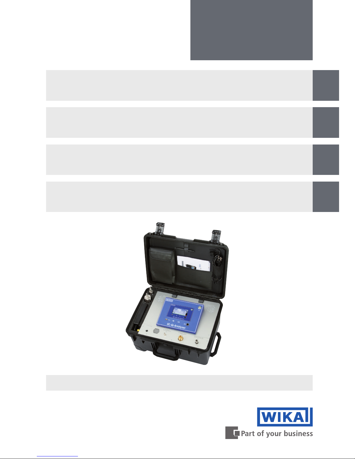
Analysegerät zur Ermittlung der Gasqualität
von Isoliergasen, Typ GA11
SF₆ gas or g³ gas
Analytic instrument for determining the quality
of insulated gases, model GA11
Instrument d‘analyse pour déterminer la
qualité du gaz isolants , Type GA11
Analizador para determinar la calidad del gas
aislante, modello GA11
Page 2

2
14065341.02 11/2016 EN/DE/FR/ES
WIKA operating instructions analytic instrument, model GA11
EN
DE
FR
ES
© 09/2016 WIKA Alexander Wiegand SE & Co. KG
All rights reserved. / Alle Rechte vorbehalten.
WIKA
®
is a registered trademark in various countries.
WIKA
®
ist eine geschützte Marke in verschiedenen Ländern.
Prior to starting any work, read the operating instructions!
Keep for later use!
Vor Beginn aller Arbeiten Betriebsanleitung lesen!
Zum späteren Gebrauch aufbewahren!
Lire le mode d'emploi avant de commencer toute opération !
A conserver pour une utilisation ultérieure !
¡Leer el manual de instrucciones antes de comenzar cualquier trabajo!
¡Guardar el manual para una eventual consulta!
Betriebsanleitung Typ GA11 Seite
39 - 74
Operating instructions model GA11 Page
3 - 38
Mode d‘emploi type GA11 Page
75 - 110
Manual de instrucciones modello GA11 Página
111 - 147
Page 3

3
WIKA operating instructions analytic instrument, model GA11
EN
14065341.02 11/2016 EN/DE/FR/ES
Contents
1. General information...............................................5
2. Design and function ..............................................6
2.1 Overview.......................................................6
2.2 Description .....................................................7
2.3 Scope of delivery ................................................8
3. Safety ..........................................................8
3.1 Intended use....................................................9
3.2 Personnel qualication...........................................10
3.3 Personal protective equipment ....................................10
3.4 Handling of insulating gases and gas mixtures .......................11
3.5 Valid standards and guidelines ....................................12
3.6 Dealing with pressure-retaining components.........................13
3.7 Residual risks..................................................13
3.8 Labelling, safety marks ..........................................13
4. Transport, packaging and storage .................................14
5. Commissioning, operation ........................................15
5.1 Battery / mains operated .........................................15
5.2 Connecting the gas compartment..................................15
5.3 Switching on and o.............................................16
5.4 Performing measurements .......................................17
5.5 Cancelling an ongoing measurement...............................19
5.6 Emptying depot and depressurised gas compartment .................20
5.7 Saving the measuring result ......................................21
5.8 Managing the saved measuring results .............................21
Contents
Page 4

4
WIKA operating instructions analytic instrument, model GA11
EN
14065341.02 11/2016 EN/DE/FR/ES
Contents
6. Settings........................................................23
6.1 Calling the settings mode ........................................23
6.2 Settings.......................................................23
6.3 System .......................................................24
6.4 Importing/exporting the list of measurement names via USB interface ....24
6.5 Limit values for gases ...........................................25
6.6 Firmware upgrade ..............................................26
7. Software Q-Analyser Measurement Viewer ..........................27
8. Maintenance and cleaning ........................................28
8.1 Maintenance...................................................28
8.2 Cleaning ......................................................28
8.3 Recalibration ..................................................28
9. Replacing sensors...............................................29
10. Faults..........................................................31
11. Dismounting, return and disposal..................................33
12. Specications ..................................................34
13. Accessories ....................................................37
Declarations of conformity can be found online at www.wika.com
Page 5

5
WIKA operating instructions analytic instrument, model GA11
EN
14065341.02 11/2016 EN/DE/FR/ES
1. General information
1. General information
■
The analytic instrument described in the operating instructions has been designed
and manufactured using state-of-the-art technology.
All components are subject to stringent quality and environmental criteria during
production. Our management systems are certied to ISO 9001 and ISO 14001.
■
These operating instructions contain important information on handling the instrument. Working safely requires that all safety instructions and work instructions are
observed.
■
Observe the relevant local accident prevention regulations and general safety regulations for the instrument’s range of use.
■
The operating instructions are part of the product and must be kept in the immediate
vicinity of the instrument and readily accessible to skilled personnel at any time.
■
Skilled personnel must have carefully read and understood the operating instructions
prior to beginning any work.
■
The manufacturer's liability is void in the case of any damage caused by using the
product contrary to its intended use, non-compliance with these operating instructions, assignment of insuciently qualied skilled personnel or unauthorised modications to the instrument.
■
The general terms and conditions contained in the sales documentation shall apply.
■
Subject to technical modications.
■
Factory calibrations/DKD/DAkkS calibrations are carried out in accordance with
international standards.
■
Further information:
- Internet address: www.wika.com/sf6
- Relevant data sheet: SP 62.11
- Application consultant:
Tel.: +49 9372 132-8971
sf6-sales@wika.com
Page 6
6
WIKA operating instructions analytic instrument, model GA11
EN
14065341.02 11/2016 EN/DE/FR/ES
2. Design and function
2. Design and function
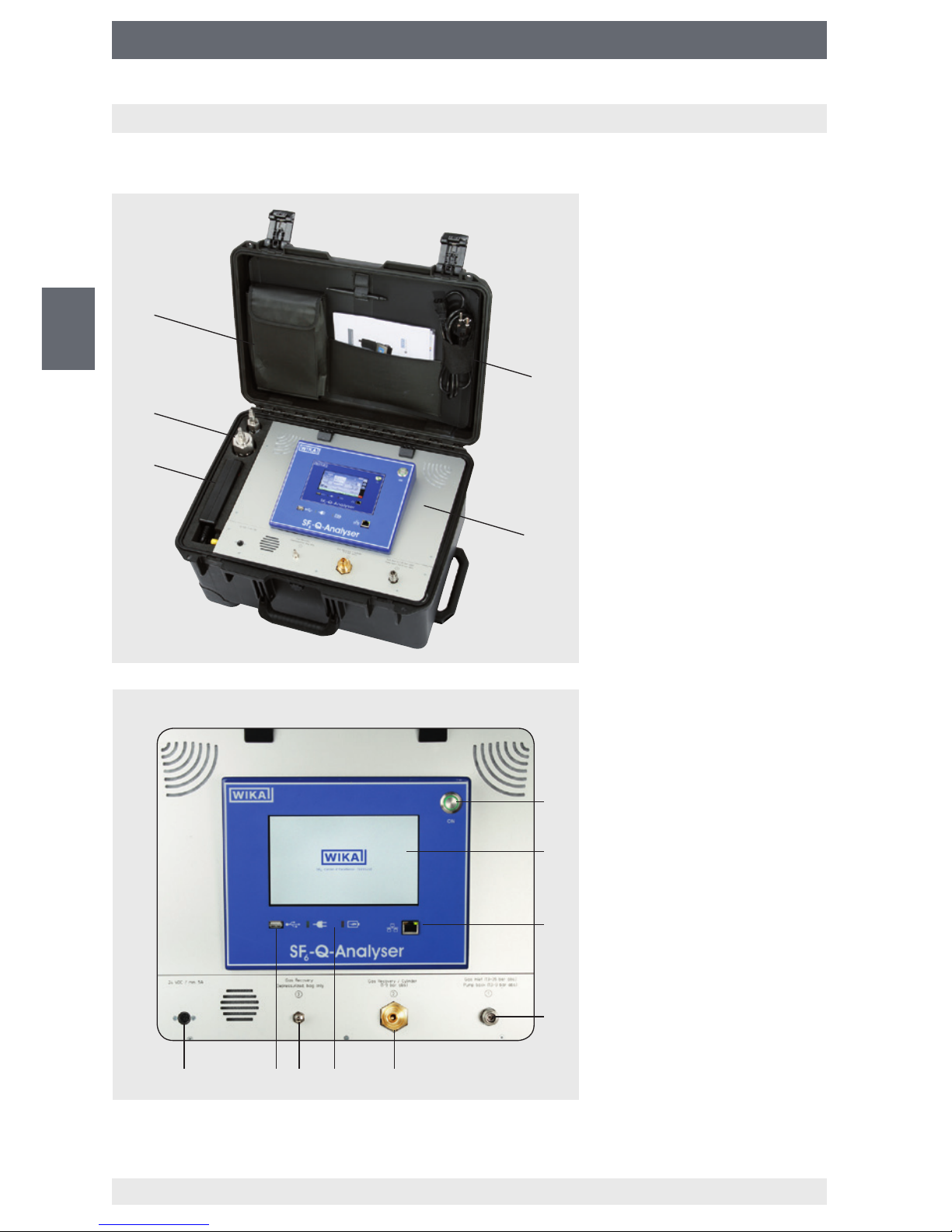
2.1 Overview
Power supply unit
Adapter
Storage for hoses
Storage for power cord
User interface
ON/OFF key
Touchscreen
Network connection (LAN)
Inlet, return pumps
Outlet, gas cylinder
Power and charging
indicators
Outlet for gas recovery bag
USB interface
Power connection
Page 7

7
WIKA operating instructions analytic instrument, model GA11
EN
14065341.02 11/2016 EN/DE/FR/ES
2. Design and function
2.2 Description
Data processing and data storage
The analytic instrument model GA11 is a multi-sensor system for examining the quality
of SF₆ gas and g³ gas, e.g. in switchgear. The basic instrument consists of a built-in
computer with touchscreen for processing and storage of up to 500 data records. The
data records can be exported via the integrated USB interface.
The accompanying software “Q-Analyser Measurement Viewer” enables you to display
the data on a PC or print the measurement reports (only for SF₆-Q-Analyser).
Extendable sensor system (only for SF₆-Q-Analyser)
The sensor system of GA11 is module-based and can be extended to up to 7 sensors.
In addition, there is the possibility of storing measuring gas internally as well as pumping
it back into the original gas compartment without losses after the measurement.
Automatic adjustment of the gas quality
After the measurement, the results will be compared with customer-specically adjustable limit values according to e.g. CIGRE B3.02.01 or IEC 60480 standards. The operator
thus obtains a reliable statement on whether the insulating gas is suitable for the given
application or not, or whether it is necessary to perform a gas processing or a gas
exchange.
There are no
standards
to compare with for g³ gas.
The operator can enter his own limit
values for quality.
Battery life
If the lithium-ion accumulator is fully charged, the analytic instrument can perform at least
5 measurements with the “back pumping” function. The number of the battery-powered
pump-back cycles is largely dependent on the tank pressure of the gas to be measured.
The GA11 sends a warning message on the display when battery is low.
If the instrument is not connected to the mains in time, it will shut down automatically in
order to prevent damages and data loss. In the mains operation, the battery is charged
and the instrument can be switched on again at the same time and operate without
restrictions.
Power and charging indicators
The front control panel has two LEDs which indicate the charging status (red) or mains
operation (green).
If an error occurs during the charge cycle, the charging indicator ashes (red).
Page 8
8
WIKA operating instructions analytic instrument, model GA11
EN
14065341.02 11/2016 EN/DE/FR/ES
2. Design and function / 3. Safety
2.3 Scope of delivery
■
Analytic instrument model GA11 in a sturdy transport case
■
Power supply unit with power cord
■
Calibration certicate
■
Touchpen
■
USB stick
■
Operating instructions
■
See delivery note for optionally ordered sensor system and accessories.
Cross-check scope of delivery with delivery note.
3. Safety
Explanation of symbols
WARNING!
... indicates a potentially dangerous situation that can result in serious injury
or death, if not avoided.
CAUTION!
... indicates a potentially dangerous situation that can result in light injuries
or damage to equipment or the environment, if not avoided.
Information
... points out useful tips, recommendations and information for ecient and
trouble-free operation.
Page 9

9
WIKA operating instructions analytic instrument, model GA11
EN
14065341.02 11/2016 EN/DE/FR/ES
3. Safety
3.1 Intended use
The analytic instrument model GA11 is available in two dierent versions:
SF
6
-Q-Analyser and g³-Q-Analyser. The GA11 is used for determining the gas quality of
the following insulating gases and gas mixtures.
Permissible insulating gases and gas mixtures for SF₆-Q-Analyser
■
SF₆ gas
■
SF₆/N₂
■
SF₆/CF₄
■
CO₂
Permissible insulating gases and gas mixtures for g³-Q-Analyser
■
g³ gas
■
CO₂
■
Novec 4710
Application areas
The instrument is especially designed for applications that full the following conditions:
■
The use is only allowed in buildings or dry surroundings.
■
Use only for commercial purposes and in industrial environment.
■
The height of the operation site should not exceed 2,000 m.
■
Ambience with max. pollution degree of 3.
■
Voltage supply of overvoltage category II.
■
Ambient temperature between 0 ... 40 °C.
■
Max. inlet pressure: 35 bar (SF₆-Q-Analyser)
■
Max. outlet pressure: 10 bar (SF₆-Q-Analyser)
■
Max. inlet pressure: 12 bar (g³-Q-Analyser)
■
Max. outlet pressure: 10 bar (g³-Q-Analyser)
The instrument has been designed and built solely for the intended use described here,
and may only be used accordingly.
Only use the instrument with original accessories from WIKA.
Refrain from unauthorised modications to the instrument.
Any use beyond or dierent to the intended use is considered as improper use.
The technical specications contained in these operating instructions must be
observed. Improper handling or operation of the instrument outside of its technical
specications requires the instrument to be taken out of service immediately and
inspected by an authorised WIKA service engineer.
Page 10
10
WIKA operating instructions analytic instrument, model GA11
EN
14065341.02 11/2016 EN/DE/FR/ES
3. Safety
Handle electronic precision measuring instruments with the required care (protect from
humidity, impacts, strong magnetic elds, static electricity and extreme temperatures,
do not insert any objects into the instrument or its openings). Plugs and sockets must be
protected from contamination.
The manufacturer shall not be liable for claims of any type based on operation contrary
to the intended use.
3.2 Personnel qualication
WARNING!
Risk of injury should qualication be insucient!
Improper handling can result in considerable injury and damage to equipment.
■
The activities described in these operating instructions may only be
carried out by skilled personnel who have the qualications described
below.
■
Keep unqualied personnel away from hazardous areas.
Trained personnel
The plant operator must ensure that the handling of SF
6
gas and g³ gas is only carried
out by a qualied company or by qualied persons which have been specially trained in
accordance with IEC 61634, section 4.3.1 or IEC 60480, section 10.3.1.
Special operating conditions require further appropriate knowledge, e.g. of aggressive
media.
3.3 Personal protective equipment
The personal protective equipment is designed to protect the skilled personnel from
hazards that could impair their safety or health during work. When carrying out the
various tasks on and with the instrument, the skilled personnel must wear personal
protective equipment.
Follow the instructions displayed in the work area regarding personal protective
equipment!
Page 11

11
WIKA operating instructions analytic instrument, model GA11
EN
14065341.02 11/2016 EN/DE/FR/ES
3. Safety
The requisite personal protective equipment must be provided by the operating company.
Wear safety goggles!
Safety goggles to EN 166, class 2.
They protect the eyes from ying parts during coupling or releasing of
the quick connections under pressure.
Wear protective gloves!
Protect hands from friction, abrasion, cuts or deep injuries and also from
contact with hot surfaces.
3.4 Handling of insulating gases and gas mixtures
SF
6
gas is a greenhouse gas which is listed in the Kyoto Protocol. SF6 gas must not be
released into the atmosphere, but must be collected in suitable containers.
Properties of insulating gases
■
Colourless and odourless
■
Chemically neutral
■
Inert
■
Not ammable
■
Heavier than air
■
No toxicity
■
No damage to the ozone layer
Detailed information is given in IEC 60376 and IEC 61634.
Danger of suocation caused by insulating gases and gas mixtures
High concentrations of gases and gas mixtures may lead to suocation, especially at
ground level or in lower-lying areas.
Page 12

12
WIKA operating instructions analytic instrument, model GA11
EN
14065341.02 11/2016 EN/DE/FR/ES
3. Safety
Danger caused by decomposition products
Insulating gas in electrical systems may contain decomposition products generated by
electric arcs:
■
Gaseous sulphur uoride
■
Sulphur hexauoride
■
Solid and atomized metal uorides, metal suldes, metal oxides
■
Hydrogen uoride
■
Sulphur dioxide
Decomposition products can be harmful to health.
■
They can cause poisoning by inhalation, ingestion or contact with the skin.
■
They may be irritating to the eyes, the respiratory system or the skin and burn them.
■
Inhalation of large quantities may damage the lungs.
Observe the following safety instructions in order to avoid danger from insulating gas:
■
Wear personal protective equipment.
■
Read the material safety data sheet of the gas supplier.
■
With large leaks, evacuate the area quickly.
■
Ensure good ventilation.
■
Ensure the leak tightness of the equipment with a leak detector (e.g. model GIR-10).
3.5 Valid standards and guidelines
Installation, assembly, commissioning:
■
BGI 753 (SF₆ plants and equipment in Germany)
■
IEC 61634 (Handling of SF₆ gas)
■
IEC 60376 (New SF₆ gas, technical grade SF₆ gas)
■
IEC 60480 (Used SF₆ gas)
■
CIGRE report 276, 2005 (Practial SF₆ gas handling instructions)
Leaks during operation:
■
IEC 60376 (New SF₆ gas, technical grade SF₆ gas)
■
IEC 60480 (Used SF₆ gas)
■
CIGRE 2002 (“SF₆ gas in the electrical industry”)
Repair work and maintenance:
■
IEC 61634 (Use and handling of SF₆ gas in high-voltage switchgear and controlgear)
■
CIGRE 1991 (Handling of SF₆ gas)
■
CIGRE report 276, 2005 (Practical SF₆ gas handling instructions)
■
CIGRE report 163, 2000 (Guide for SF₆ gas mixtures)
Insulating gas is a colourless and odourless, chemically neutral, inert and
non-inammable gas which is heavier than air, not toxic and not harmful to
the ozone layer. Detailed information is given in IEC 60376 and IEC 61634.
Page 13
13
WIKA operating instructions analytic instrument, model GA11
EN
14065341.02 11/2016 EN/DE/FR/ES
3. Safety
3.6 Dealing with pressure-retaining components
Pneumatic energy can lead to serious injury.
With damaged individual components, highly pressurised air can escape and cause eye
injuries, for example.
Pressure-retaining components (e.g. adapters, hoses and external containers) may
explode due to overpressure.
Observe the following safety instructions in order to avoid danger from pneumatic
energy:
■
Depressurise the instrument before starting any work on it. Be careful of the accumulator, and ensure it is fully discharged.
■
Do not alter the pressure settings above the maximum permissible levels.
■
Make sure that all pressure-retaining components are designed for the quoted
nominal pressures (→ see chapter 12 “Specications”).
3.7 Residual risks
Despite compliance with all relevant safety regulations for the design and construction
of our instruments as well as intended use of them by the operator, residual risks may
occur during operation.
Residual risks are described in detail in the individual chapters. It is vital that you comply
with all safety instructions.
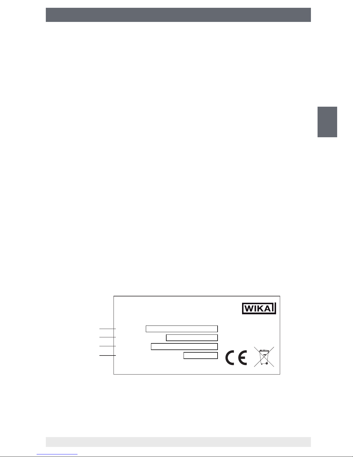
3.8 Labelling, safety marks
Product label (example)
The product label is located at the rear of the display frame.
Product designation (model)
Power supply
Serial no.
Date of manufacture
WIKA
Alexander Wiegand SE & Co. KG, 63911 Klingenberg, Germany
Product:
Power Supply:
Serial No:
Manufacturing Year:
Made in Germany
Page 14

14
WIKA operating instructions analytic instrument, model GA11
EN
14065341.02 11/2016 EN/DE/FR/ES
4. Transport, packaging and storage
4. Transport, packaging and storage
4.1 Transport
Check the analytic instrument for any damage that may have been caused by transport.
Obvious damage must be reported immediately.
4.2 Packaging
Do not remove packaging until just before mounting.
Keep the packaging as it will provide optimum protection during transport (e.g. calibration,
sending for repair).
4.3 Storage
Permissible conditions at the place of storage:
Storage temperature: 0 ... 40 °C
Avoid exposure to the following factors:
■
Direct sunlight or proximity to hot objects
■
Mechanical vibration, mechanical shock (putting it down hard)
■
Soot, vapour, dust and corrosive gases
■
Hazardous environments, ammable atmospheres
■
Storage outdoors or in humid environment
■
Unauthorized access
Page 15
15
WIKA operating instructions analytic instrument, model GA11
EN
14065341.02 11/2016 EN/DE/FR/ES
5. Commissioning, operation
5. Commissioning, operation
Depending on the version of the analytic instrument, the user interface may dier from
those illustrated in these operating instructions. However, the procedure is always the
same.
5.1 Battery / mains operated
The analytic instrument can be operated in battery mode and in the mains supply.
If the lithium-ion accumulator is fully charged, the analytic instrument can perform at least
5 measurements with the “back pumping” function. The number of the battery-powered
pump-back cycles is largely dependent on the tank pressure of the gas to be measured.
The GA11 sends a warning message on the display when battery is low.
If the instrument is not connected to the mains in time, it will shut down automatically in
order to prevent damages and data loss. In the mains operation, the battery is charged
and the instrument can be switched on again at the same time and operate without
restrictions.
Establishing connection to mains supply
1. Connect power supply unit to the power cord.
2.
Connect power supply unit to mains connection on the operating panel.
3.
Connect the power cord to the socket.
⇒
Connection to mains supply is established.
5.2 Connecting the gas compartment
CAUTION!
Escaping SF₆ gas results in environmental hazards!
If there are leakages at the connecting elements, the environmentally
hazardous SF₆ gas may be released to the atmosphere.
▶
Make sure that there is no leakage at any connections (e.g. by using gas
detector GIR-10).
To perform a measurement, the pressure of the gas compartment to be measured has
to be at least 1.3 bar abs. If the inlet pressure is below 1.3 bar abs., it is possible to use
an inlet pressure control unit (e.g. model GA05) to raise the pressure.
5.2.1 Pumping back in the measured gas compartment
▶
Connect “Inlet, return pumps ” to the gas compartment.
⇒
The gas compartment is connected.
During back pumping, the gas is pumped back into the gas compartment via the “Inlet,
return pumps ”.
Page 16
16
WIKA operating instructions analytic instrument, model GA11
EN
14065341.02 11/2016 EN/DE/FR/ES
5. Commissioning, operation
5.2.2 Back pumping in external gas compartment (pressurised)
Requirement:
The lling pressure of the external gas compartment is between 1.3 ... 10 bar abs.
(SF₆-Q-Analyser)
The lling pressure of the external gas compartment is between 1.3 ... 12 bar abs.
(g³-Q-Analyser)
1.
Connect “Inlet, return pumps ” to the gas compartment to be measured.
2.
Connect “Outlet for gas cylinder ” to the external gas compartment.
⇒
The gas compartment is connected.
5.2.3 Back pumping in external gas compartment (depressurised)
1.
Connect “Inlet, return pumps ” to the gas compartment to be measured.
2.
Connect “Outlet for gas recovery bag ” to the external gas compartment.
⇒
The gas compartment is connected.
5.3 Switching on and o
Switching on
▶
Press On/Off switch.
⇒
A self-test is performed.
⇒
The residual gas is filtered.
⇒
The instrument is ready for operation.
⇒
Start screen with sensor values is displayed (the actual display may vary from the
example).
Switching o
▶
Press the following button.
▶
Page 17
17
WIKA operating instructions analytic instrument, model GA11
EN
14065341.02 11/2016 EN/DE/FR/ES
5. Commissioning, operation
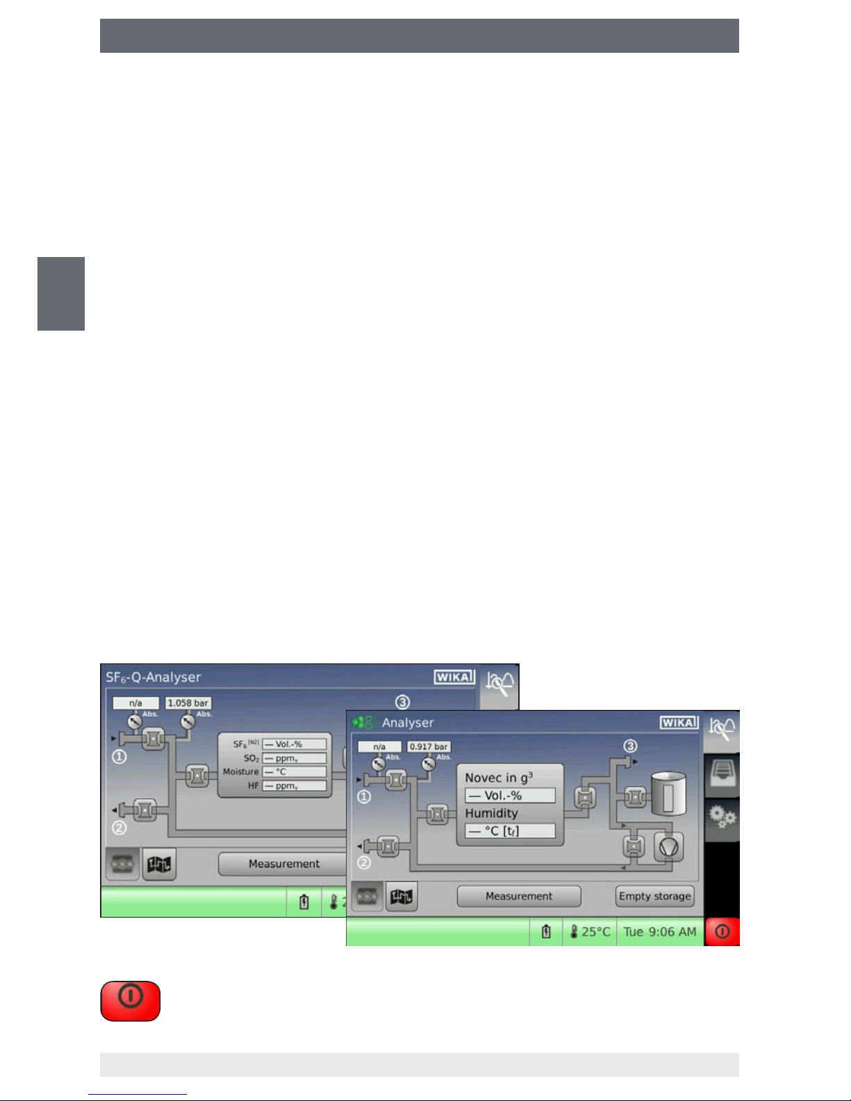
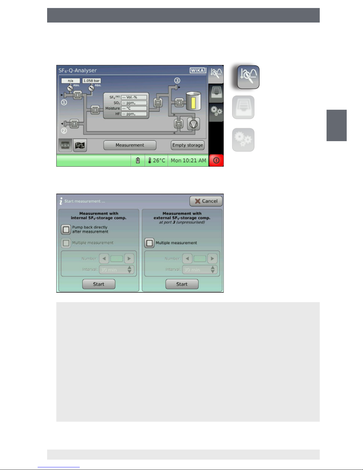
5.4 Performing measurements
1. Press “Measurement”.
2. Congure the measuring methods and press “Start” to conrm.
⇒
The measurement begins.
Measurement with internal depot
The measuring gas will be stored temporarily in the internal depot and later be pumped back
into the gas compartment to be measured or a pressurised external gas compartment.
Measurement with external container (depressurised)
The measuring gas will be directly pumped into a depressurised external gas compartment
(e.g. gas recovery bag, model GA45).
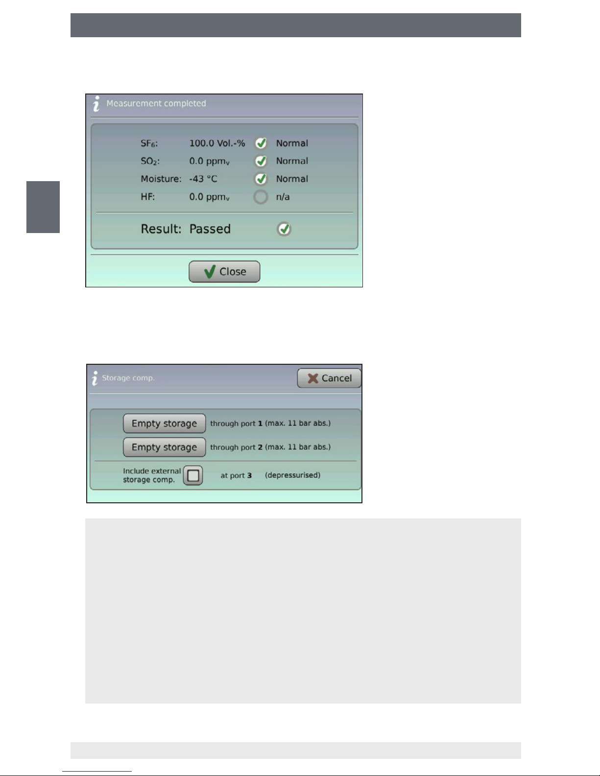
Back pumping after the measurement
Once the measurement is nished, a selection window will open, which enables the selection of the storage location.
Multiple measurement
The multiple measurement makes it possible to perform the gas quality check at specic
intervals automatically.
Measurement
Data management
Settings
Page 18
18
WIKA operating instructions analytic instrument, model GA11
EN
14065341.02 11/2016 EN/DE/FR/ES
5. Commissioning, operation
3. Save or skip the measuring result.
4. Select the gas compartment for back pumping the measuring gas (only available
when the “back pumping” function is selected).
⇒
Measuring gas is pumped back.
⇒
Measurement is finished.
Connection
The measuring gas is directly pumped back into the measured gas compartment.
Connection
The measuring gas is pumped into a pressurised external gas compartment (e.g. gas cylinder).
The maximal pumping capacity of the analytic instrument is:
■
10 bar abs. (SF₆-Q-Analyser)
■
12 bar abs. (g³-Q-Analyser)
External container
With the function activated, the measuring gas is emptied from an external container at
connection as well.
Page 19
19
WIKA operating instructions analytic instrument, model GA11
EN
14065341.02 11/2016 EN/DE/FR/ES
5. Commissioning, operation
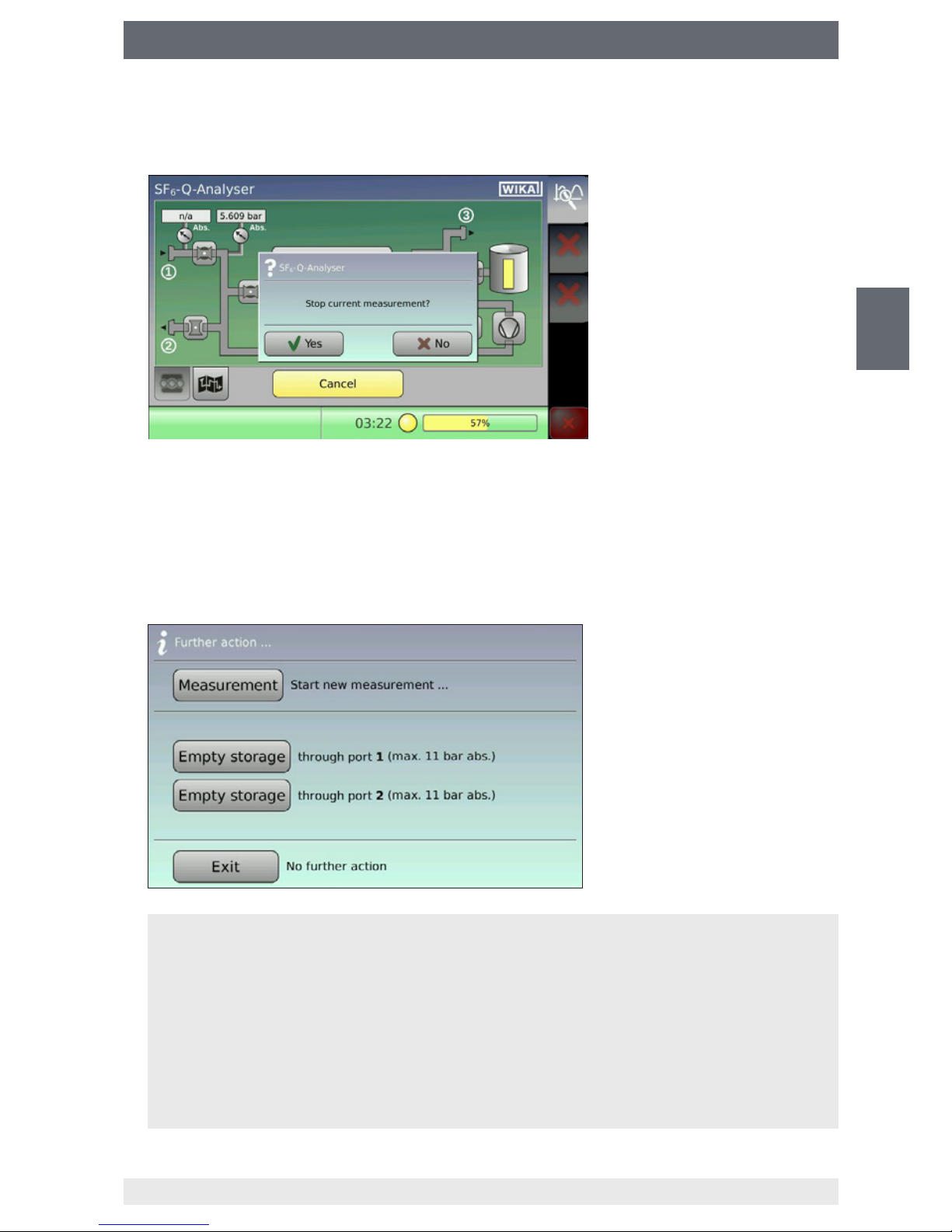
5.5 Cancelling an ongoing measurement
1. Press “Cancel” and conrm by pressing “Yes”.
2. Select the gas compartment for back pumping the measuring gas (only available
when the “back pumping” function is selected).
⇒
Measuring gas is pumped back.
⇒
Measurement is finished.
Connection
The measuring gas is directly pumped back into the measured gas compartment.
Connection
The measuring gas is pumped into a pressurised external gas compartment (e.g. gas cylinder).
The maximal pumping capacity of the analytic instrument is:
■
10 bar abs. (SF₆-Q-Analyser)
■
12 bar abs. (g³-Q-Analyser)
Page 20
20
WIKA operating instructions analytic instrument, model GA11
EN
14065341.02 11/2016 EN/DE/FR/ES
5. Commissioning, operation
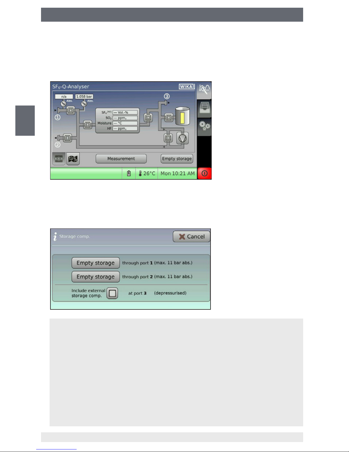
5.6 Emptying depot and depressurised gas compartment
The depot can be emptied only when there is measuring gas inside. If the depot is
already empty, the procedure is cancelled with an error message.
1. Press “Empty depot”.
2. Select the gas compartment for back pumping the measuring gas (only available
when the “back pumping” function is selected).
⇒
Measuring gas is pumped back.
⇒
Measurement is finished.
Connection
The measuring gas is directly pumped back into the measured gas compartment.
Connection
The measuring gas is pumped into a pressurised external gas compartment (e.g. gas cylinder).
The maximal pumping capacity of the analytic instrument is:
■
10 bar abs. (SF₆-Q-Analyser)
■
12 bar abs. (g³-Q-Analyser)
External container
With the function activated, the measuring gas is emptied from an external container at
connection as well.
Page 21
21
WIKA operating instructions analytic instrument, model GA11
EN
14065341.02 11/2016 EN/DE/FR/ES
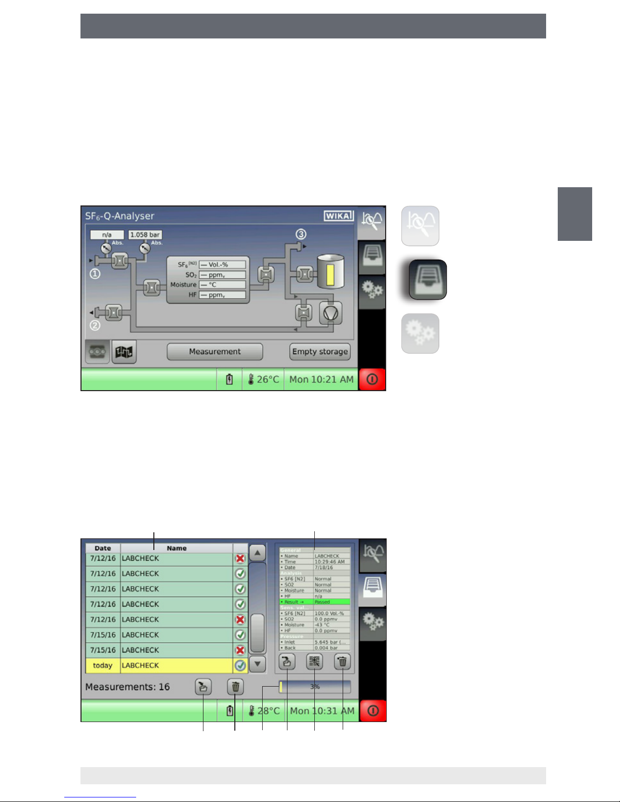
5. Commissioning, operation
Data record list
Detail window of the selected
data record
Deletes the selected data
record
Opens the data record details
in a magnied window
Saves the selected data
record on the USB data carrier
Memory utilization in %
Delete all data records
Save all data records to the
USB data carrier
5.7 Saving the measuring result
The easiest way is to use the name allocation in advance on a PC. You can create a
name list (separated by commas) and load it into the analytic instrument via the USB
interface (see chapter 6.4 “Importing/exporting the list of measurement names via USB
interface”).
5.8 Managing the saved measuring results
The main menu “Data management” must be enabled in order to access the data
management of the analytic instrument.
5.8.1 Internal memory
The internal memory can save up to 500 data records.
Depending on system setting, when the memory limit is reached, the instrument will
either send an error message or automatically overwrite the oldest data records without
warning (see chapter 6.4 “Importing/exporting the list of measurement names via USB
interface”). The data records deposited in the internal memory can be transmitted to a
USB data carrier.
Measurement
Data management
Settings
Page 22
22
WIKA operating instructions analytic instrument, model GA11
EN
14065341.02 11/2016 EN/DE/FR/ES
5. Commissioning, operation
Transmitting data records to the USB data carrier
1. Connect USB data carrier to the USB interface.
2.
■
Copying all data records to the USB data carrier
Press button [8].
■
Copying individual data records to the USB data carrier
Choose a data record via the touchscreen (the data record will be marked in
yellow) and press button [5].
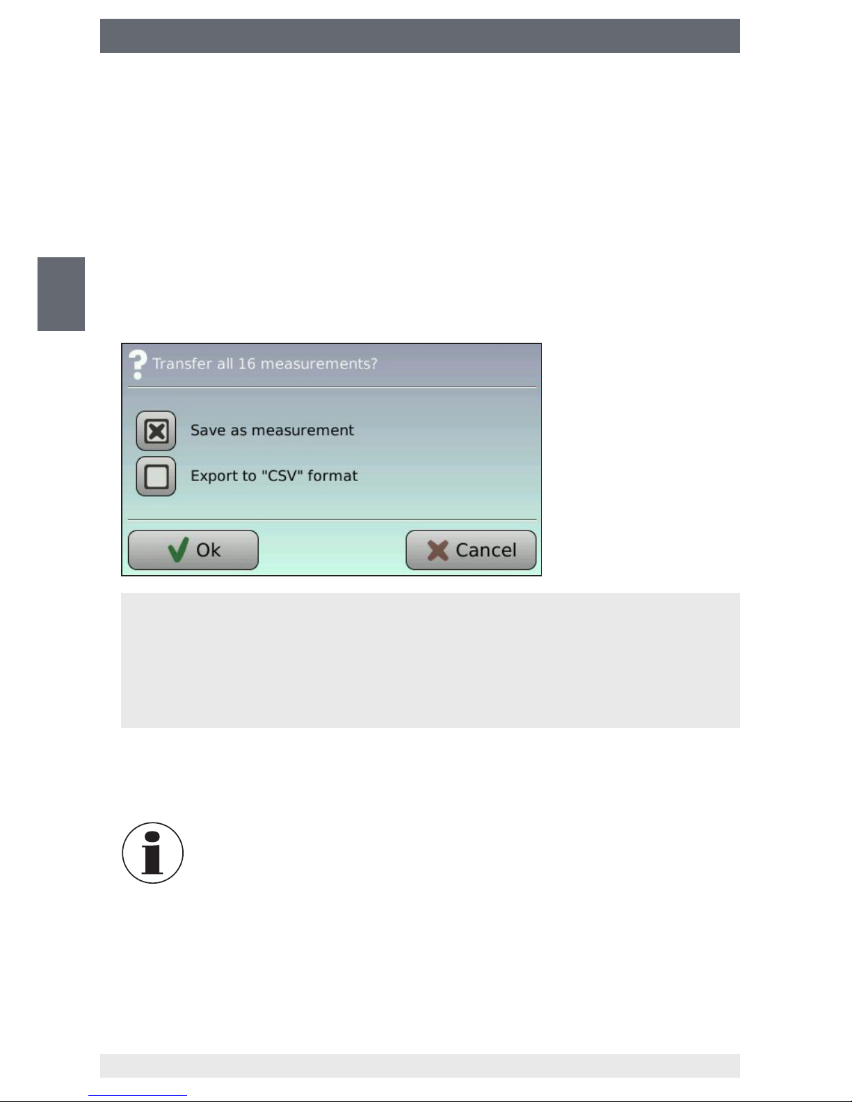
3. Select le format and conrm with “OK”.
Saving as measurement (*.mea)
The data record is saved in the analytic instrument's own format (*.mea)
Exporting in “CSV” format (*.csv)
The data record is saved in *.csv format. This format is supported by spreadsheet
programs (e.g. Microsoft Excel
®
).
4. Remove the USB data carrier once the saving process is nished (when the
hourglass symbol is extinguished).
In order to avoid data loss, only remove the USB data carrier when
the saving process is completed (when the hourglass symbol is
extinguished).
Page 23
23
WIKA operating instructions analytic instrument, model GA11
EN
14065341.02 11/2016 EN/DE/FR/ES
6. Settings
6. Settings
6.1 Calling the settings mode
The main menu “Settings” must be enabled before settings to the analytic instrument
can be made.
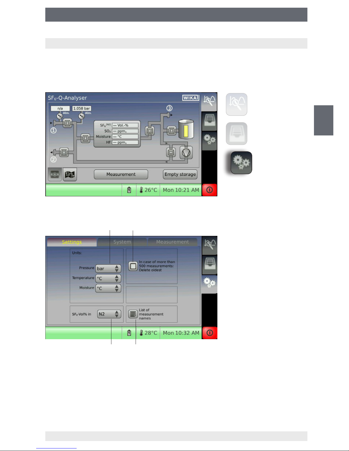
6.2 Settings
Setting the units
Activated: The oldest data records will be deleted when the limit of 500 data records is reached.
Deactivated: There will be an error message “Memory is full” when the limit of 500 data records is reached.
Importing/exporting the list of measurement names via USB interface
Calibration gas of SF6 percentage sensor
Measurement
Data management
Settings
Page 24
24
WIKA operating instructions analytic instrument, model GA11
EN
14065341.02 11/2016 EN/DE/FR/ES
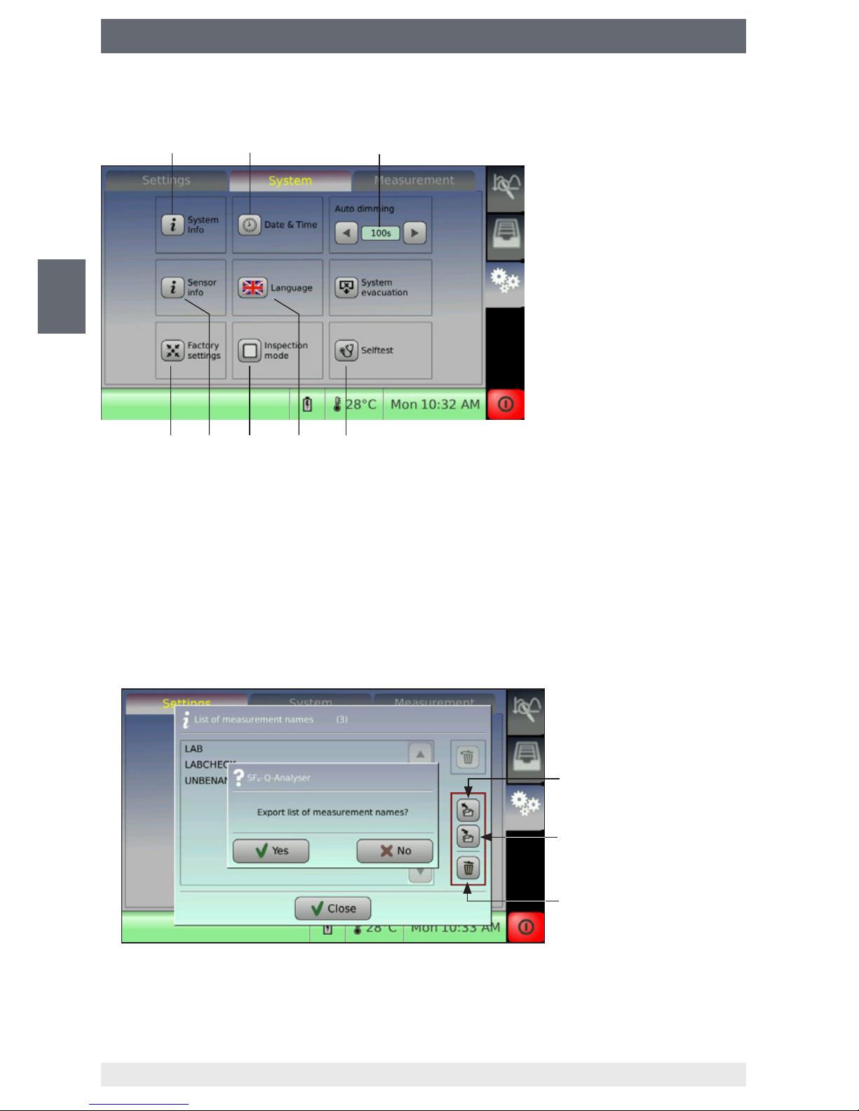
6. Settings
6.3 System
6.4 Importing/exporting the list of measurement names via USB interface
1. Create a list with any word processing program.
Separate measurement names with commas from each other:
Name1, Name2, Name3, ...
2. Save the list to the USB data carrier (le format is *.csv).
3. The list can be imported by clicking the icon on the analytic instrument. The imported
list will overwrite the existing list in the internal memory of the analytic instrument.
Import the list from the USB
data carrier
Export the list to the USB
data carrier
Delete the list
Information on the system
Setting date and time
After expiration of this time, the
display lighting will be dimmed
for energy saving.
Performing self-test
Changing language
The inspection mode is reserved
for WIKA service.
Information on the sensor
system
Reset to factory settings
Page 25
25
WIKA operating instructions analytic instrument, model GA11
EN
14065341.02 11/2016 EN/DE/FR/ES
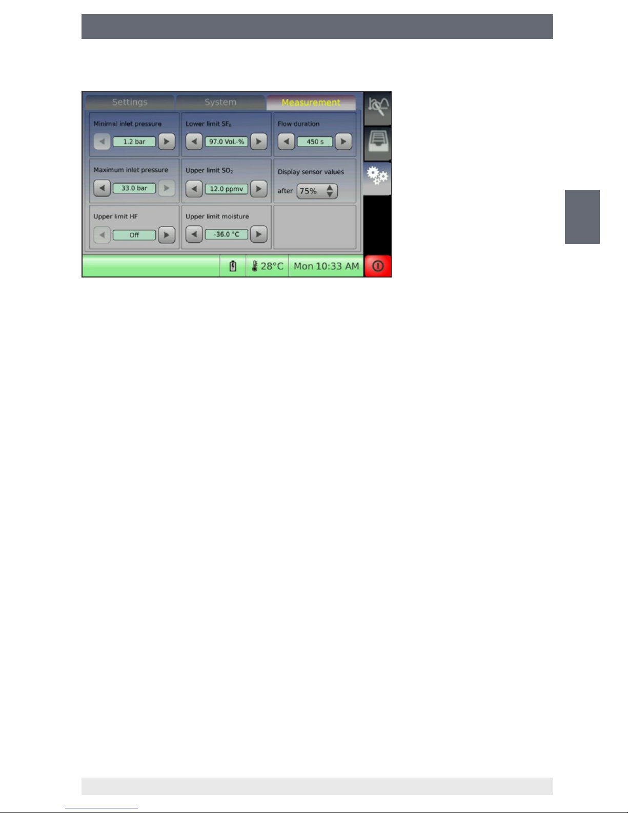
6. Settings
6.5 Limit values for gases
SF₆-Q-Analyser
The factory settings are the limits for the reusable SF
6
gas according to the Cigré
Recycling Guide or IEC 60480. The limits of the installed sensors can be adjusted
according to customer guidelines.
■
Lower limit of SF6: 97.0 Vol.-%
■
Upper limit of SO2: 12 ppm
v
■
Upper limit of humidity: -36.0 °C dew point
■
Flow duration: 450 seconds, ow duration = measurement duration
g³-Q-Analyser
The factory settings are preset to 0 %. There are no standards to compare with for g³
gas. The operator can enter his own limit values for quality.
Default:
■
Lower limit of g³: 3% default
■
Upper limit of humidity: -36.0 °C dew point
■
Flow duration: 450 seconds, ow duration = measurement duration
Page 26
26
WIKA operating instructions analytic instrument, model GA11
EN
14065341.02 11/2016 EN/DE/FR/ES
6. Settings
6.6 Firmware upgrade
You can update the analytic instrument by upgrading the rmware.
The latest rmware can be downloaded from www.wika.de.
CAUTION!
Incomplete rmware upgrade may cause damage to the instrument!
If the power supply is terminated during the rmware installation, the instrument may be damaged.
■
Do not disconnect the analytic instrument from the mains or shut it down
during installation.
■
Ensure continuous voltage supply.
Performing upgrade
1. Download rmware from www.wika.de.
Unzip the le (*.zip) in the dened directory “UPGRADE” on the USB data carrier
(drive letter:\UPGRADE).
2. Connect USB data carrier to the switched o analytic instrument.
3. Connect the analytic instrument to the mains (no battery operation).
4. Switch on analytic instrument.
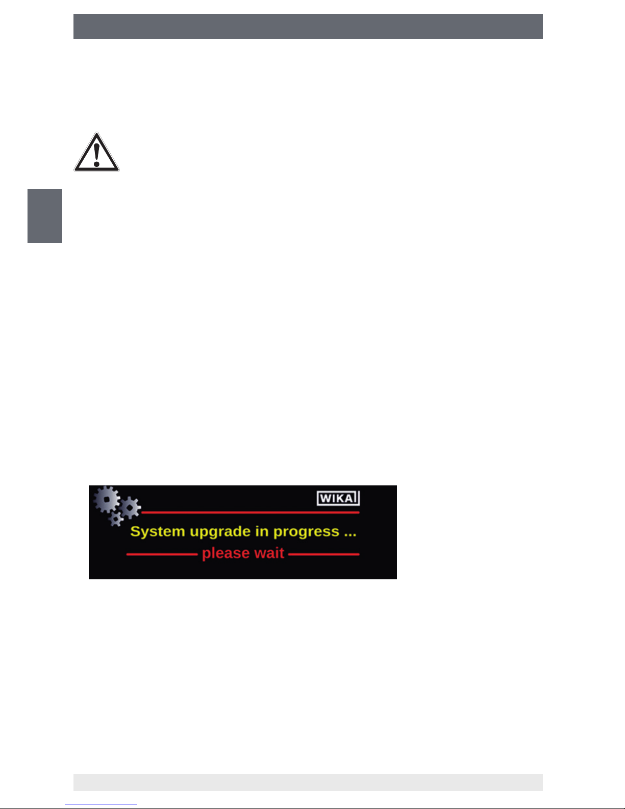
5. Wait until the installation is nished. Do not disconnect the analytic instrument from
the mains during installation.
The following screen will appear during installation.
6. Calibrate the touchscreens. Conrm the positions of 5 cross hairs with the touchpen.
7. Disconnect the USB data carrier from the analytic instrument after the “Update
completed” message shows up.
Page 27
27
WIKA operating instructions analytic instrument, model GA11
EN
14065341.02 11/2016 EN/DE/FR/ES
7. Software Q-Analyser Measurement Viewer
7. Software Q-Analyser Measurement Viewer
Functional description
The enclosed USB stick and the CD-ROM contain the software (only for SF₆-Q-Analyser).
System requirements:
■
Operating system: Microsoft® Windows® or Linux
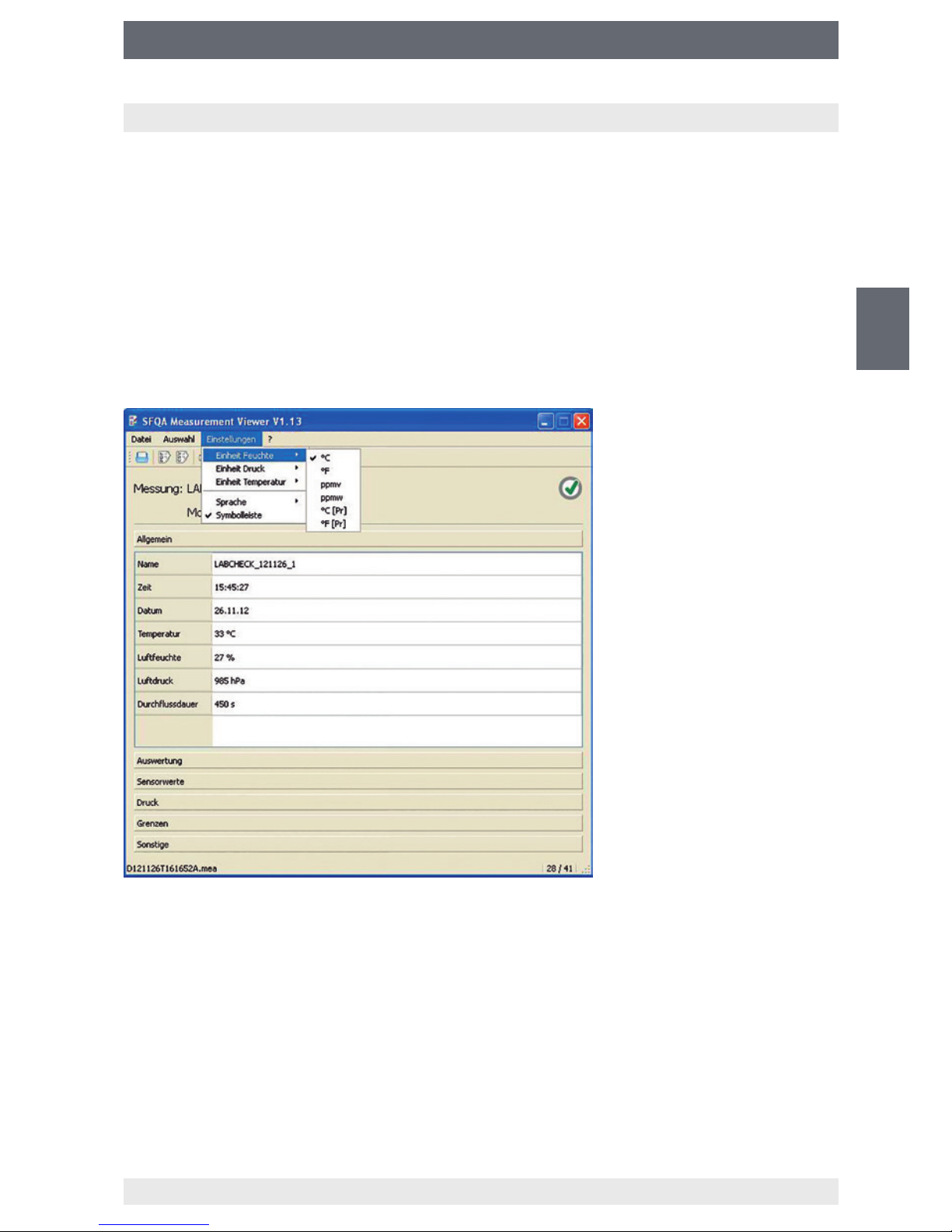
This easy-to-use tool makes it possible to view the measurement les (*.mea) of the
analytic instrument, to print them out or to export them as PDF or CSV les.
The measuring results can be subsequently displayed in other units.
For the sake of clarity, the individual les are arranged in categories.
Click on the corresponding category (e.g. sensor values) to show the les.
Printing and exporting the measured data
You can generate a print report or PDF report to ensure reliable documentation and
ling of the measured data Click the respective entry or the button in the menu “File”.
It is possible to generate a CSV le from the measured data for further data evaluation,
which can be opened by spreadsheet programs.
Page 28
28
WIKA operating instructions analytic instrument, model GA11
EN
14065341.02 11/2016 EN/DE/FR/ES
8. Maintenance and cleaning
8. Maintenance and cleaning
8.1 Maintenance
Repairs and maintenances must only be carried out by the manufacturer or manufacturer-approved service partners.
8.2 Cleaning
CAUTION!
■
Clean the instrument with a moist cloth.
■
Electrical connections must not come into contact with moisture.
■
Wash or clean the dismounted instrument before returning it, in order to
protect persons and the environment from exposure to residual media.
■
Residual media in the dismounted instrument can result in a risk to
persons, the environment and equipment.
Take sucient precautionary measures.
For information on returning the instrument see chapter 11.2 “Return”.
8.3 Recalibration
We recommend that the analytic instrument is regularly recalibrated by the manufacturer. In addition, every factory calibration includes a free-of-charge check of all system
parameters with respect to their compliance with the specication. The basic settings
will be corrected if necessary.
SF₆-Q-Analyser: 2 years
g³-Q-Analyser: 1 year
The time until the next recalibration for each individual sensor can be queried under
“Sensor info”.
Settings > System > Sensor info
Page 29
29
WIKA operating instructions analytic instrument, model GA11
EN
14065341.02 11/2016 EN/DE/FR/ES
9. Replacing sensors
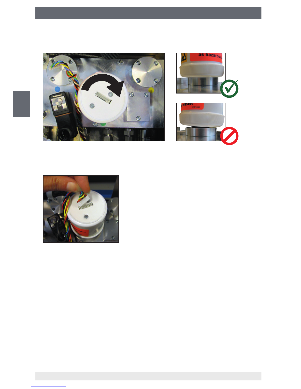
9. Replacing sensors
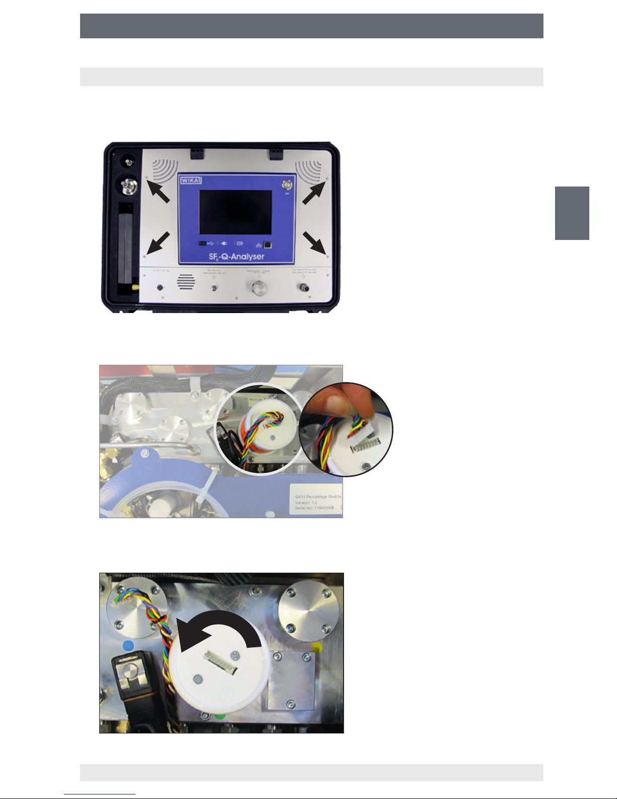
1. Switch o the analytic instrument and remove the front panel.
Remove the 4 screws of the front panel (see arrows) and fold back the front panel.
2. Pull the plug o the sensor (in this example: SO
2
sensor)
3. Screw out the sensor counterclockwise.
Page 30
30
WIKA operating instructions analytic instrument, model GA11
EN
14065341.02 11/2016 EN/DE/FR/ES
9. Replacing sensors
4. Screw in the new sensor in clockwise direction.
Screw in the sensor in a straight manner because it can easily tilt.
5. Connect the plug to the sensor.
The plug can only be inserted in one direction. The groove prevents the plug from
being inserted in a wrong way.
6. Reassemble the front panel and switch on the instrument (see step 1).
⇒
The sensor is recognised automatically.
7. Flood the analytic instrument with pure gas.
Perform 3 measurements with pure gas.
Page 31

31
WIKA operating instructions analytic instrument, model GA11
EN
14065341.02 11/2016 EN/DE/FR/ES
10. Faults
10. Faults
Faults Causes Measures
USB data carrier is full The limit of the USB data carrier's
storage capacity is reached
Connect a new USB data carrier or
free up the capacity.
Error on the USB data carrier Access to the USB data carrier
failed.
Plug in/pull out the USB data carrier
or use another USB data carrier.
The content of the USB data carrier
cannot be read.
Error reading the USB data carrier. Plug in/pull out the USB data carrier
or use another USB data carrier.
Error during transmission of the
measurement
Write error on the USB data carrier Check the USB data carrier via PC,
and format or repair it, if necessary.
Copy process failed Copy process to the USB data
carrier failed.
Check the USB data carrier and
repeat the process.
Measurement could not be saved. Write error on the USB data carrier Plug in/pull out the USB data carrier
or use another USB data carrier.
Depot is full The intake capacity of the internal
depot is exhausted.
Empty the depot (see chapter 6.8
“Emptying depot”)
Back pressure too high The gas container into which the
measuring gas has been pumped is
under high pressure.
Connect a gas container with lower
pressure.
Back pressure too low The measured back pressure is
too low.
The minimum pressure is atmospheric pressure.
---
Inlet pressure too high The pressure at the inlet is too high. Use external pressure reducer
Inlet pressure too low The pressure at the inlet is too low. Use inlet pressure control unit for
gas analytic instruments (e.g. model
GA05).
Depot pressure too high The pressure in internal gas depot
is too high.
Empty the depot (see chapter 6.8
“Emptying depot”)
The capacity of 500 measurements
is reached.
The capacity of 500 measurements
is reached.
Manually delete the measurements
or activate the option “Automatic
deletion” (see chapter 6.10.1
“System settings”).
Page 32

32
WIKA operating instructions analytic instrument, model GA11
EN
14065341.02 11/2016 EN/DE/FR/ES
10. Faults
For the special case that the system does not respond to user inputs any longer, it is
possible to switch o the system by pressing and holding down the On/O switch for
approx. 7 seconds.
In normal operation, always shut down the instrument with the red button on the touch-
screen (see chapter 5.3 “Switching on and o”).
Repairs and maintenances must only be carried out by the manufacturer or manufacturer-approved service partners.
One exception here is the replacement or the extension of sensors.
Please contact us before returning the instrument.
WIKA Alexander Wiegand SE & Co. KG
info@wika.de
www.wika.com/sf6
CAUTION!
If faults cannot be eliminated by means of the measures listed above, the
instrument must be shut down immediately, it must be ensured that pressure
is no longer present, and it must be prevented from being inadvertently put
back into service.
In this case, contact the manufacturer.
If a return is needed, please follow the instructions given in chapter 11.2
“Return”.
Page 33

33
WIKA operating instructions analytic instrument, model GA11
EN
14065341.02 11/2016 EN/DE/FR/ES
11. Dismounting, return and disposal
11. Dismounting, return and disposal
WARNING!
Residual media at the analytic instrument can result in a risk to persons, the
environment and equipment.
Take sucient precautionary measures.
11.1 Dismounting
Only disconnect the analytic instrument once the system has been depressurised!
11.2 Return
WARNING!
Strictly observe the following when shipping the instrument:
All instruments delivered to WIKA must be free from any kind of hazardous
substances (acids, bases, solutions etc.).
When returning the instrument, use the original packaging or a suitable transport
packaging.
To avoid damage:
Pack the transport case in a outer carton and mark the package with “sensitive measuring instrument”.
Information on returns can be found under the heading “Service” on our local
website.
11.3 Disposal
Incorrect disposal can put the environment at risk.
Dispose of instrument components and packaging materials in an environmentally
compatible way and in accordance with the country-specic waste disposal regulations.
This marking on the instruments indicates that they must not be disposed of
in domestic waste. The disposal is carried out by return to the manufacturer
or by the corresponding municipal authorities (see EU directive
2002/96/EC).
Page 34

34
WIKA operating instructions analytic instrument, model GA11
EN
14065341.02 11/2016 EN/DE/FR/ES
12. Specications
12. Specications
Specications SF₆-Q-Analyser g³-Q-Analyser
Connections
Inlet/return pumps Quick coupling with self-sealing valve
Outlet for gas cylinder Self-sealing valve DN8
Outlet for gas recovery bag Quick coupling, self-sealing valve
Permissible pressure ranges
Inlet/return pumps 1.3 ... 35 bar abs. /1.3 ... 10 bar abs. 1.3 ... 35 bar abs. /1.3 ... 12 bar abs.
Outlet for gas cylinder 1.3 ... 10 bar abs. 1.3 ... 12 bar abs.
Outlet for gas recovery bag < 1.015 bar abs. < 1.015 bar abs.
TFT touchscreen
Display size 7"
Resolution 800 x 480
Colours 262,144
Voltage supply
Battery power Lithium-ion battery, battery is charged during mains supply mode
Mains operated AC 90 ... 264 V (50 ... 60 Hz)
Permissible temperature ranges
Operation 0 ... 40 °C
Storage -20 ... +60 °C
Flow measuring gas
20 litres/hour
Dimensions
W x H x D: 538 x 406 x 297 mm
Weight
approx. 25 kg
SF₆ percentage sensor
Measuring principle Sound velocity N/A
Measuring range 0 ... 100 %
Accuracy ±0.5 % based on SF₆/N₂ mixtures
(calibration for SF₆/CF₄ mixtures on
request)
Resolution 0.1 %
Page 35

35
WIKA operating instructions analytic instrument, model GA11
EN
14065341.02 11/2016 EN/DE/FR/ES
12. Specications
Specications SF₆-Q-Analyser g³-Q-Analyser
g³ percentage sensor
Measuring principle N/A Sound velocity
Measuring range 0 ... 10 % (share in Novec 4710)
Accuracy ±0,3 % based on Novec 4710 / CO₂
mixtures
Humidity sensor
Measuring principle Polymer-based capacitive humidity sensor
Measuring range -60 ... +20 °C dew point
Accuracy ±2 °C dew point at -40 ...+20 °C dew point
±4 °C dew point at < -40 °C dew point
Resolution 1 °C
Units °Ctd / °Ftd / ppmw / ppmv / °Ctdpr / °Ftdpr
(dew point at gas compartment pressure, relative to the ambient pressure
and temperature-compensated at 20 °C)
Calibration interval 2 years 1 year
SO2 sensor (option)
Measuring principle Electrochemical N/A
Measuring range In combination with HF sensor, only 0
… 10 or 0 … 20 ppm
v
make sense.
■
0 ... 10 ppm
v
■
0 ... 20 ppm
v
■
0 ... 100 ppm
v
■
0 ... 500 ppm
v
Accuracy ±0.5 ppmv (measuring range 0 ... 10
ppm
v
)
±1 ppm
v
(measuring range 0 ... 20
ppm
v
)
±3 ppm
v
(measuring range 0 ... 100
ppm
v
)
±5 ppm
v
(measuring range 0 ... 500
ppm
v
)
Resolution 0.1 ppm
v
Permissible humidity ≤ 90 % r. h. (non-condensing)
Max. zero oset 0.1 ppm
v
Long-term stability < 1 % signal degradation/month (linear)
< 0.5 % at 0 ... 500 ppm
v
Service life 2 years starting from installation
Page 36

36
WIKA operating instructions analytic instrument, model GA11
EN
14065341.02 11/2016 EN/DE/FR/ES
12. Specications
Specications SF₆-Q-Analyser g³-Q-Analyser
HF sensor, hydrogen uoride (option)
Measuring principle Electrochemical N/A
Measuring range 0 ... 10 ppm
v
Accuracy ±1 ppm
v
Resolution 0.1 ppm
v
Permissible humidity ≤ 90 % r. h. (non-condensing)
Max. zero oset 0.1 ppm
v
Long-term stability < 1 % signal degradation/month (linear)
Service life 2 years starting from installation
H₂S sensor (option)
Measuring principle Electrochemical N/A
Measuring range 0 ... 100 ppm
v
Accuracy ±5 ppm
v
Resolution 0.1 ppm
v
Permissible humidity ≤ 90 % r. h. (non-condensing)
Max. zero oset 0.1 ppm
v
Long-term stability < 1 % signal degradation/month (linear)
Service life 2 years starting from installation
CO sensor (option)
Measuring principle Electrochemical N/A
Measuring range 0 ... 500 ppm
v
Accuracy ±9 ppm
v
Resolution 0.1 ppm
v
Permissible humidity ≤ 90 % r. h. (non-condensing)
Max. zero oset 0.1 ppm
v
Long-term stability < 1 % signal degradation/month (linear)
Service life 2 years starting from installation
Page 37

37
WIKA operating instructions analytic instrument, model GA11
EN
14065341.02 11/2016 EN/DE/FR/ES
13. Accessories
13. Accessories
Description Order no.
Gas recovery bag, model GA45
■
Low weight and easily transportable
■
Cost-eective version to prevent SF6 gas
emissions
■
Compatible with all WIKA gas analytic instruments
■
With overpressure valve as burst protection
■
Resistant to decomposition products
■
Storage capacity 110 litres
For further specications see data sheet SP 62.08
14013015
Replacement sensor HF measuring range 0 … 10 ppm 14071765
Replacement sensor H
2
S measuring range 0 … 100 ppm 14071786
Replacement sensor CO measuring range 0 … 500 ppm 14071769
Replacement sensor SO
2
measuring range 0 … 20 ppm 14071736
Replacement sensor SO
2
measuring range 0 … 100 ppm 14071745
Replacement sensor SO
2
measuring range 0 … 500 ppm 14071746
Page 38

38
WIKA operating instructions analytic instrument, model GA11
EN
14065341.02 11/2016 EN/DE/FR/ES
Page 39

39
WIKA Betriebsanleitung Analysegerät, Typ GA11
DE
14065341.02 11/2016 EN/DE/FR/ES
Inhalt
1. Allgemeines ....................................................41
2. Aufbau und Funktion.............................................42
2.1 Überblick......................................................42
2.2 Beschreibung ..................................................43
2.3 Lieferumfang...................................................44
3. Sicherheit ......................................................44
3.1 Bestimmungsgemäße Verwendung ................................45
3.2 Personalqualikation ............................................46
3.3 Persönliche Schutzausrüstung . . . . . . . . . . . . . . . . . . . . . . . . . . . . . . . . . . . .46
3.4 Umgang mit Isoliergasen und Gasgemischen........................47
3.5 Geltende Normen und Richtlinien..................................48
3.6 Umgang mit druckführenden Teilen ................................49
3.7 Restgefahren ..................................................49
3.8 Beschilderung, Sicherheitskennzeichnungen ........................49
4. Transport, Verpackung und Lagerung ..............................50
5. Inbetriebnahme, Betrieb..........................................51
5.1 Akku- / Netzbetrieb .............................................51
5.2 Gasraum anschließen ...........................................51
5.3 Ein- und ausschalten ............................................52
5.4 Messungen durchführen .........................................53
5.5 Laufende Messung abbrechen....................................55
5.6 Depot und drucklosen Gasraum entleeren ..........................56
5.7 Messergebnis speichern .........................................57
5.8 Gespeicherte Messergebnisse verwalten ...........................57
Inhalt
Page 40

40
WIKA Betriebsanleitung Analysegerät, Typ GA11
DE
14065341.02 11/2016 EN/DE/FR/ES
Inhalt
6. Einstellungen ...................................................59
6.1 Einstellungsmodus aufrufen ......................................59
6.2 Einstellungen ..................................................59
6.3 System .......................................................60
6.4 Import/Export der Liste der Messungsnamen ........................60
6.5 Grenzwerte für Gase ............................................61
6.6 Firmware upgrade ..............................................62
7. Software Q-Analyser Measurement Viewer ..........................63
8. Wartung und Reinigung ..........................................64
8.1 Wartung ......................................................64
8.2 Reinigung .....................................................64
8.3 Rekalibrierung .................................................64
9. Sensoren tauschen ..............................................65
10. Störungen......................................................67
11. Demontage, Rücksendung und Entsorgung .........................69
12. Technische Daten ...............................................70
13. Zubehör........................................................73
Konformitätserklärungen nden Sie online unter www.wika.de.
Page 41

41
WIKA Betriebsanleitung Analysegerät, Typ GA11
DE
14065341.02 11/2016 EN/DE/FR/ES
1. Allgemeines
1. Allgemeines
■
Das in der Betriebsanleitung beschriebene Analysegerät wird nach dem aktuellen
Stand der Technik konstruiert und gefertigt.
Alle Komponenten unterliegen während der Fertigung strengen Qualitäts- und
Umweltkriterien. Unsere Managementsysteme sind nach ISO 9001 und ISO 14001
zertiziert.
■
Diese Betriebsanleitung gibt wichtige Hinweise zum Umgang mit dem Gerät. Voraussetzung für sicheres Arbeiten ist die Einhaltung aller angegebenen Sicherheitshinweise und Handlungsanweisungen.
■
Die für den Einsatzbereich des Gerätes geltenden örtlichen Unfallverhütungsvorschriften und allgemeinen Sicherheitsbestimmungen einhalten.
■
Die Betriebsanleitung ist Produktbestandteil und muss in unmittelbarer Nähe des
Gerätes für das Fachpersonal jederzeit zugänglich aufbewahrt werden.
■
Das Fachpersonal muss die Betriebsanleitung vor Beginn aller Arbeiten sorgfältig
durchgelesen und verstanden haben.
■
Die Haftung des Herstellers erlischt bei Schäden durch bestimmungswidrige
Verwendung, Nichtbeachten dieser Betriebsanleitung, Einsatz ungenügend qualizierten Fachpersonals sowie eigenmächtiger Veränderung am Gerät.
■
Es gelten die allgemeinen Geschäftsbedingungen in den Verkaufsunterlagen.
■
Technische Änderungen vorbehalten.
■
Werkskalibrierungen/DKD/DAkkS-Kalibrierungen erfolgen nach internationalen
Normen.
■
Weitere Informationen:
- Internet-Adresse: www.wika.de/sf6
- zugehöriges Datenblatt: SP 62.11
- Anwendungsberater:
Tel.: +49 9372 132-8971
sf6-sales@wika.com
Page 42

42
WIKA Betriebsanleitung Analysegerät, Typ GA11
DE
14065341.02 11/2016 EN/DE/FR/ES
2. Aufbau und Funktion
2. Aufbau und Funktion
2.1 Überblick
Netzteil
Adapter
Aufbewahrung für
Schläuche
Aufbewahrung für Netzkabel
Bedienoberäche
EIN-/AUS-Taste
Touchscreen
Netzwerkanschluss (LAN)
Eingang, Rückpumpen
Ausgang, Gaszylinder
Netz- und Ladeanzeige
Ausgang für
Gasauangbeutel
USB-Schnittstelle
Netzanschluss
Page 43

43
WIKA Betriebsanleitung Analysegerät, Typ GA11
DE
14065341.02 11/2016 EN/DE/FR/ES
2. Aufbau und Funktion
2.2 Beschreibung
Datenverarbeitung und -speicherung
Das Analysegerät Typ GA11 ist ein Multi-Sensor-System zur Prüfung der Gasqualität
von SF₆-Gas und g³-Gas, z. B. in Schaltanlagen. Das Basisgerät besteht aus einem
eingebauten Computer mit Touchscreen zur Datenverarbeitung und -speicherung von
bis zu 500 Datensätzen. Die Datensätze können über die integrierte USB-Schnittstelle
exportiert werden.
Mit der mitgelieferten Software “Q-Analyser Measurement Viewer” ist es möglich die
Daten am PC darzustellen bzw. Messprotokolle zu drucken (nur für SF₆-Q-Analyser).
Erweiterbare Sensorik (nur SF₆-Q-Analyser)
Die Sensorik des GA11 ist modular und kann auf bis zu 7 Sensoren erweitert werden.
Darüber hinaus besteht die Möglichkeit Messgas intern zu speichern und nach der
Messung verlustfrei in den ursprünglichen Gasraum zurückzupumpen.
Automatischer Abgleich der Gasqualität
Nach der Messung werden die Ergebnisse mit kundenspezisch einstellbaren
Grenzwerten z. B. nach CIGRE B3.02.01 oder IEC 60480 verglichen. Der Bediener
erhält dadurch eine verlässliche Aussage, ob das Isoliergas für den Einsatzfall geeignet
ist oder eine Gasaufbereitung bzw. ein Gasaustausch durchgeführt werden muss.
Für g³-Gas gibt es keine Normen die abgeglichen werden. Hier können vom Benutzer
eigene Limits für die Qualität eingepegt werden.
Akkulaufzeit
Mit komplett geladenem Lithium-Ionen-Akkumulator kann das Analysegerät mindestens
5 Messungen mit der Rückpumpfunktion durchführen. Die Anzahl der akkubetriebenen
Rückpumpzyklen hängt stark von dem Behälterdruck des zu messenden Gases ab.
Das GA11 gibt eine Warnmeldung bei niedriger Akkuladung auf dem Display aus.
Wird das Gerät nicht rechtzeitig mit dem Stromnetz verbunden, so wird es automa
tisch zum Schutz vor Schäden und Datenverlust ausgeschaltet. Im Netzbetrieb lädt die
Batterie und das Gerät kann parallel wieder eingeschaltet und ohne Einschränkungen
betrieben werden.
Netz- und Ladeanzeige
Zwei LEDs in der Bedienfront signalisieren den Ladestatus (rot) bzw. Netzbetrieb (grün).
Tritt während des Ladezyklus eine Störung auf, blinkt die Ladeanzeige (rot).
Page 44

44
WIKA Betriebsanleitung Analysegerät, Typ GA11
DE
14065341.02 11/2016 EN/DE/FR/ES
2. Aufbau und Funktion / 3. Sicherheit
2.3 Lieferumfang
■
Analysegerät Typ GA11 in einem robusten Transportkoer
■
Netzteil mit Netzkabel
■
Kalibrierzertikat
■
Touchpen
■
USB-Stick
■
Betriebsanleitung
■
Optional bestellte Sensorik und Zubheör, siehe Lieferschein
Lieferumfang mit dem Lieferschein abgleichen.
3. Sicherheit
Symbolerklärung
WARNUNG!
… weist auf eine möglicherweise gefährliche Situation hin, die zum Tod oder
zu schweren Verletzungen führen kann, wenn sie nicht gemieden wird.
VORSICHT!
… weist auf eine möglicherweise gefährliche Situation hin, die zu geringfügigen oder leichten Verletzungen bzw. Sach- und Umweltschäden führen
kann, wenn sie nicht gemieden wird.
Information
… hebt nützliche Tipps und Empfehlungen sowie Informationen für einen
ezienten und störungsfreien Betrieb hervor.
Page 45

45
WIKA Betriebsanleitung Analysegerät, Typ GA11
DE
14065341.02 11/2016 EN/DE/FR/ES
3. Sicherheit
3.1 Bestimmungsgemäße Verwendung
Das Analysegerät Typ GA11 ist in in zwei Ausführungen erhältlich, dem SF
6
-Q-Analyser
und dem g³-Q-Analyser. Das GA11 dient der Ermittlung der Gasqualität der folgenden
Isoliergase und Gasgemische.
Zulässige Isoliergase und Gasgemische für SF₆-Q-Analyser
■
SF₆-Gas
■
SF₆/N₂
■
SF₆/CF₄
■
CO₂
Zulässige Isoliergase und Gasgemische für g³-Q-Analyser
■
g³-Gas
■
CO₂
■
Novec 4710
Einsatzbereiche
Das Gerät ist für Einsatzbereiche konstruiert worden, welche folgende Bedingungen
erfüllen:
■
Der Einsatz darf nur in Gebäuden oder trockener Umgebung erfolgen.
■
Einsatz nur für gewerbliche Zwecke und in industrieller Umgebung.
■
Einsatzort liegt bei max. 2.000 m.
■
Umgebung mit max. Verschmutzungsgrad 3.
■
Spannungsversorgung der Überspannungskategorie II.
■
Umgebungstemperatur zwischen 0 … 40 °C.
■
Max. Eingangsdruck 35 bar (SF₆-Q-Analyser)
■
Max. Ausgangsdruck 10 bar (SF₆-Q-Analyser)
■
Max. Eingangsdruck 12 bar (g³-Q-Analyser)
■
Max. Ausgangsdruck 10 bar (g³-Q-Analyser)
Das Gerät ist ausschließlich für den hier beschriebenen bestimmungsgemäßen Verwendungszweck konzipiert und konstruiert und darf nur dementsprechend verwendet werden.
Das Gerät nur mit Originalzubehör von WIKA betreiben.
Eigenmächtige Umbauten am Gerät unterlassen.
Jede über die bestimmungsgemäße Verwendung hinausgehende oder andersartige
Benutzung gilt als Fehlgebrauch.
Die technischen Spezikationen in dieser Betriebsanleitung sind einzuhalten. Eine
unsachgemäße Handhabung oder ein Betreiben des Gerätes außerhalb der technis-
chen Spezikationen macht die sofortige Stilllegung und Überprüfung durch einen
autorisierten WIKA-Servicemitarbeiter erforderlich.
Page 46

46
WIKA Betriebsanleitung Analysegerät, Typ GA11
DE
14065341.02 11/2016 EN/DE/FR/ES
3. Sicherheit
Elektronische Präzisionsmessgeräte mit erforderlicher Sorgfalt behandeln (vor Nässe,
Stößen, starken Magnetfeldern, statischer Elektrizität und extremen Temperaturen
schützen, keine Gegenstände in das Gerät bzw. Önungen einführen). Stecker und
Buchsen vor Verschmutzung schützen.
Ansprüche jeglicher Art aufgrund von nicht bestimmungsgemäßer Verwendung sind
ausgeschlossen.
3.2 Personalqualikation
WARNUNG!
Verletzungsgefahr bei unzureichender Qualikation!
Unsachgemäßer Umgang kann zu erheblichen Personen- und
Sachschäden führen.
■
Die in dieser Betriebsanleitung beschriebenen Tätigkeiten nur durch
Fachpersonal nachfolgend beschriebener Qualikation durchführen
lassen.
■
Unqualiziertes Personal von den Gefahrenbereichen fernhalten.
Geschultes Personal
Der Betreiber muss sicherstellen, dass die Handhabung von SF
6
-Gas und g³-Gas durch
ein hierzu qualiziertes Unternehmen oder von gemäß IEC 61634 Abschnitt 4.3.1 bzw.
IEC 60480 Abschnitt 10.3.1 geschulten Mitarbeitern durchgeführt wird.
Spezielle Einsatzbedingungen verlangen weiteres entsprechendes Wissen, z. B. über
aggressive Medien.
3.3 Persönliche Schutzausrüstung
Die persönliche Schutzausrüstung dient dazu, das Fachpersonal gegen Gefahren
zu schützen, die dessen Sicherheit oder Gesundheit bei der Arbeit beeinträchtigen
könnten. Beim Ausführen der verschiedenen Arbeiten an und mit dem Gerät muss das
Fachpersonal persönliche Schutzausrüstung tragen.
Im Arbeitsbereich angebrachte Hinweise zur persönlichen Schutzausrüstung
befolgen!
Page 47

47
WIKA Betriebsanleitung Analysegerät, Typ GA11
DE
14065341.02 11/2016 EN/DE/FR/ES
3. Sicherheit
Die erforderliche persönliche Schutzausrüstung muss vom Betreiber zur Verfügung
gestellt werden.
Schutzbrille tragen!
Schutzbrille nach EN 166, Klasse 2.
Schutz der Augen vor umheriegenden Teilen beim Kuppeln bzw. lösen der
Schnellverbindungen unter Druck.
Schutzhandschuhe tragen!
Schutz der Hände vor Reibung, Abschürfung, Einstichen oder tieferen
Verletzungen sowie vor Berührung mit heißen Oberächen.
3.4 Umgang mit Isoliergasen und Gasgemischen
SF
6
-Gas ist ein Treibhausgas, das im Kyoto-Protokoll gelistet ist. Das SF6-Gas darf
nicht in die Atmosphäre gelangen, sondern muss in geeigneten Behältern gesammelt
werden.
Eigenschaften von Isoliergasen
■
Farb- und geruchlos
■
Chemisch neutral
■
Inert
■
Nicht entammbar
■
Schwerer als Luft
■
Keine Toxizität
■
Nicht ozonschädigend
Detaillierte Angaben benden sich in der IEC 60376 und IEC 61634.
Erstickungsgefahr durch Isoliergase und Gasgemische
Hohe Konzentrationen von Gasen und Gasgemischen können zur Erstickung führen.
Insbesondere in Bodennähe oder tiefer gelegenen Räumen.
Page 48

48
WIKA Betriebsanleitung Analysegerät, Typ GA11
DE
14065341.02 11/2016 EN/DE/FR/ES
3. Sicherheit
Gefährdung duch Zersetzungsprodukte
Isoliergas in elektrischen Anlagen kann durch Lichtbogeneinwirkung Zersetzungsprodukte enthalten:
■
Gasförmige Schwefelouride
■
Schwefeloxyuoride
■
Feste staubförmige Metalluoride, -sulde und -oxide
■
Fluorwassersto
■
Schwefeldoxid
Zersetzungsprodukte können gesundheitsschädlich sein.
■
Durch Einatmen, Verschlucken oder Hautberührung kann es zu einer Vergiftung
kommen.
■
Augen, Atmungsorgane oder die Haut kann gereizt und verätzt werden.
■
Durch Einatmen größerer Mengen kann die Lunge geschädigt werden.
Folgende Sicherheitshinweise beachten, um Gefahren durch Isoliergas zu vermeiden:
■
Persönliche Schutzausrüstung tragen.
■
Das Sicherheitsdatenblatt des Gaslieferanten lesen.
■
Bei großen Leckagen schnell den Ort verlassen.
■
Für gute Belüftung sorgen.
■
Dichtigkeit der Betriebsmittel mit Lecksuchgerät sicherstellen (z. B. Typ GIR-10).
3.5 Geltende Normen und Richtlinien
Installation, Errichtung, Inbetriebnahme:
■
BGI 753 (SF₆-Anlagen und Betriebsmittel in Deutschland)
■
IEC 61634 (Handhabung von SF₆-Gas)
■
IEC 60376 (neues SF6-Gas, technisches SF₆-Gas)
■
IEC 60480 (gebrauchtes SF₆-Gas)
■
CIGRE report 276, 2005 (Practial SF₆ gas handling instructions)
Leckagen während des Betriebs:
■
IEC 60376 (neues SF₆-Gas, technisches SF₆-Gas)
■
IEC 60480 (gebrauchtes SF₆-Gas)
■
CIGRE 2002 („SF₆ gas in the electrical industry“)
Reparaturarbeiten und Wartung:
■
IEC 61634 (Use and handling of SF₆ gas in high-voltage switchgear and controlgear)
■
CIGRE 1991 (Handhabung von SF₆-Gas)
■
CIGRE report 276, 2005 (Practical SF₆ gas handling instructions)
■
CIGRE report 163, 2000 (Guide for SF₆ gas mixtures)
Isoliergas ist farb- und geruchlos, chemisch neutral, inert, nicht entammbar
und schwerer als Luft, nicht toxisch und nicht ozonschädigend. Detaillierte
Angaben benden sich in der IEC 60376 und IEC 61634.
Page 49

49
WIKA Betriebsanleitung Analysegerät, Typ GA11
DE
14065341.02 11/2016 EN/DE/FR/ES
3. Sicherheit
3.6 Umgang mit druckführenden Teilen
Pneumatische Energien können schwerste Verletzungen verursachen.
Bei Beschädigungen einzelner Bauteile kann Luft unter hohem Druck austreten und
z. B. die Augen schädigen.
Druckführende Teile (z. B. Adapter, Schläuche und externe Behälter), können durch
Überdruck explodieren.
Folgende Sicherheitshinweise beachten, um Gefahren durch pneumatische Energien
zu vermeiden:
■
Vor Beginn von Arbeiten am Gerät dieses zuerst drucklos machen. Auf Druckspeicher achten und diesen vollständig entspannen.
■
Druckeinstellungen nicht über die maximal zulässigen Werte hinaus verändern.
■
Sicherstellen, dass alle druckführenden Teile für die angegebenen Nenndrücke
ausgelegt sind (→ siehe Kapitel 12 „Technische Daten“).
3.7 Restgefahren
Trotz Beachtung aller einschlägigen Sicherheitsvorschriften für Konzeption und Bau
unserer Geräte und trotz bestimmungsgemäßer Verwendung durch den Betreiber,
können während des Betriebs Restgefahren auftreten.
In den einzelnen Kapiteln wird speziell auf die Restrisiken hingewiesen. Alle Sicherheitshinweise unbedingt einhalten.
3.8 Beschilderung, Sicherheitskennzeichnungen
Typenschild (Beispiel)
Das Typenschild bendet sich an der Rückseite des Displayrahmens.
Produktbezeichnung (Typ)
Hilfsenergie
Serien-Nr.
Herstelldatum
WIKA
Alexander Wiegand SE & Co. KG, 63911 Klingenberg, Germany
Product:
Power Supply:
Serial No:
Manufacturing Year:
Made in Germany
Page 50

50
WIKA Betriebsanleitung Analysegerät, Typ GA11
DE
14065341.02 11/2016 EN/DE/FR/ES
4. Transport, Verpackung und Lagerung
4. Transport, Verpackung und Lagerung
4.1 Transport
Das Analysegerät auf eventuell vorhandene Transportschäden untersuchen.
Oensichtliche Schäden unverzüglich mitteilen.
4.2 Verpackung
Verpackung erst unmittelbar vor der Montage entfernen.
Die Verpackung aufbewahren, denn diese bietet bei einem Transport einen optimalen
Schutz (z. B. Kalibrierung, Reparatursendung).
4.3 Lagerung
Zulässige Bedingungen am Lagerort:
Lagertemperatur: 0 ... 40 °C
Folgende Einüsse vermeiden:
■
Direktes Sonnenlicht oder Nähe zu heißen Gegenständen
■
Mechanische Vibration, mechanischer Schock (hartes Aufstellen)
■
Ruß, Dampf, Staub und korrosive Gase
■
Explosionsgefährdete Umgebung, entzündliche Atmosphären
■
Lagerung im Freien oder in feuchter Umgebung
■
Unbefugter Zugri
Page 51

51
WIKA Betriebsanleitung Analysegerät, Typ GA11
DE
14065341.02 11/2016 EN/DE/FR/ES
5. Inbetriebnahme, Betrieb
5. Inbetriebnahme, Betrieb
Je nach Ausführung des Analysegerätes kann die Bedienoberäche von den Abbildungen in dieser Betriebsanleitung abweichen. Die Vorgehensweise ist jedoch immer
gleich.
5.1 Akku- / Netzbetrieb
Das Analysegerät kann sowohl im Akku- oder Netzbetrieb betrieben werden.
Mit komplett geladenen Lithium-Ionen Akkumulator kann das Analysegerät mindestens
5 Messungen mit der Rückpumpfunktion durchführen. Die Anzahl der akkubetriebenen
Rückpumpzyklen hängt stark von dem Behälterdruck des zu messenden Gases ab.
Das GA11 gibt eine Warnmeldung bei niedriger Akkuladung auf dem Display aus.
Wird das Gerät nicht rechtzeitig mit dem Stromnetz verbunden, so wird es automa
tisch zum Schutz vor Schäden und Datenverlust ausgeschaltet. Im Netzbetrieb lädt die
Batterie und das Gerät kann parallel wieder eingeschaltet und ohne Einschränkungen
betrieben werden.
Netzbetrieb herstellen
1. Netzteil und Netzkabel verbinden.
2.
Netzteil mit Netzanschluss auf der Bedienoberäche verbinden.
3.
Netzkabel mit Steckdose verbinden.
⇒
Netzbetrieb hergestellt.
5.2 Gasraum anschließen
VORSICHT!
Umweltgefährdung durch austretendes SF₆-Gas!
Durch Leckagen an den Verbindungselementen kann umweltgefährdendes
SF₆-Gas in die Atmosphäre gelangen.
▶
Sicherstellen, dass die Verbindungen leckagefrei sind (z. B. mit dem
Gasdetektor GIR-10)
Für eine Messung muss der Druck des zu messenden Gasraumes mindestens
1,3 bar abs. betragen. Sollte der Druck unter 1,3 bar abs. sein, kann eine Vordruckregeleinheit (z. B. Typ GA05) eingesezt werden, um den Druck zu erhöhen.
5.2.1 Rückpumpen in gemessenen Gasraum
▶
„Eingang, Rückpumpen “ mit Gasraum verbinden.
⇒
Gasraum ist angeschlossen.
Beim Rückpumpen wird das Gas über den „Eingang, Rückpumpen “ zürück in den
Gasraum gepumpt.
Page 52

52
WIKA Betriebsanleitung Analysegerät, Typ GA11
DE
14065341.02 11/2016 EN/DE/FR/ES
5. Inbetriebnahme, Betrieb
5.2.2 Rückpumpen in externen Gasraum (unter Druck stehend)
Vorraussetzung:
Fülldruck des externen Gasraumes zwischen 1,3 ... 10 bar abs. (SF₆-Q-Analyser)
Fülldruck des externen Gasraumes zwischen 1,3 ... 12 bar abs. (g³-Q-Analyser)
1.
„Eingang, Rückpumpen “ mit zu messendem Gasraum verbinden.
2.
„Ausgang für Gaszylinder “ mit externem Gasraum verbinden.
⇒
Gasraum ist angeschlossen.
5.2.3 Rückpumpen in externen Gasraum (drucklos)
1.
„Eingang, Rückpumpen “ mit zu messendem Gasraum verbinden.
2.
„Ausgang für Gasauangbeutel “ mit externem Gasraum verbinden.
⇒
Gasraum ist angeschlossen.
5.3 Ein- und ausschalten
Einschalten
▶
Ein-/Austaster betätigen.
⇒
Selbstest wird durchgeführt.
⇒
Restgas wird gefiltert.
⇒
Gerät betriebsbereit.
⇒
Startbildschirm mit Sensorwerten wird angezeigt (Beispiel kann abweichen).
Ausschalten
▶
Folgende Schaltfläche betätigen.
▶
Page 53

53
WIKA Betriebsanleitung Analysegerät, Typ GA11
DE
14065341.02 11/2016 EN/DE/FR/ES
5. Inbetriebnahme, Betrieb
5.4 Messungen durchführen
1. „Messung“ drücken.
2. Messverfahren kongurieren und mit „Start“ bestätigen.
⇒
Messung beginnt.
Messung mit internem Depot
Das Messgas wird im internen Depot zwischengespeichert, um es später in den zu messenden Gasraum oder einen unter Druck stehenden externen Gasraum zurückzupumpen.
Messung mit externem Behälter (drucklos)
Das Messgas wird direkt in einen drucklosen externen Gasraum gepumpt
(z. B. Gasauangbeutel Typ GA45).
Rückpumpen nach Messung
Nach beendeter Messung önet sich ein Auswahlfenster, in dem der Speicherort ausgewählt werden kann.
Mehrfache Messung
Die mehrfache Messung bietet die Möglichkeit, die Gasqualität in vorgegebenen Intervallen
automatisch durchführen zu lassen.
Messung
Datenverwaltung
Einstellungen
Page 54

54
WIKA Betriebsanleitung Analysegerät, Typ GA11
DE
14065341.02 11/2016 EN/DE/FR/ES
5. Inbetriebnahme, Betrieb
3. Messergebnis speichern oder überspringen.
4. Gasraum auswählen, in den das Messgas zurückgepumpt werden soll (nur wenn
Rückpumpfunktion ausgewählt wurde).
⇒
Messgas wird zurückgepumpt.
⇒
Messung ist beendet.
Anschluss
Das Messgas wird direkt in den gemessenen Gasraum zurückgepumpt.
Anschluss
Das Messgas wird in einen unter Druck stehenden externen Gasraum gepumpt
(z. B. Gaszylinder).
Maximale Pumpleistung des Analysegerätes beträgt:
■
10 bar abs. (SF₆-Q-Analyser)
■
12 bar abs. (g³-Q-Analyser)
Externer Behälter
Bei aktivierter Funktion, wird das Messgas aus einem externen Behälter an Anschluss
ebenfalls entleert.
Page 55

55
WIKA Betriebsanleitung Analysegerät, Typ GA11
DE
14065341.02 11/2016 EN/DE/FR/ES
5. Inbetriebnahme, Betrieb
5.5 Laufende Messung abbrechen
1. „Abbrechen“ drücken und mit „Ja“ bestätigen.
2. Gasraum auswählen, in den das Messgas zurückgepumpt werden soll (nur wenn
Rückpumpfunktion ausgewählt wurde).
⇒
Messgas wird zurückgepumpt.
⇒
Messung ist beendet.
Anschluss
Das Messgas wird direkt in den gemessenen Gasraum zurückgepumpt.
Anschluss
Das Messgas wird in einen unter Druck stehenden externen Gasraum gepumpt
(z. B. Gaszylinder).
Maximale Pumpleistung des Analysegerätes beträgt:
■
10 bar abs. (SF₆-Q-Analyser)
■
12 bar abs. (g³-Q-Analyser)
Page 56

56
WIKA Betriebsanleitung Analysegerät, Typ GA11
DE
14065341.02 11/2016 EN/DE/FR/ES
5. Inbetriebnahme, Betrieb
5.6 Depot und drucklosen Gasraum entleeren
Das Depot kann nur geleert werden, wenn sich Messgas darin bendet. Ist das Depot
bereits leer, bricht der Vorgang mit einer Fehlermeldung ab.
1. „Depot leeren“ drücken.
2. Gasraum auswählen, in den das Messgas zurückgepumpt werden soll (nur wenn
Rückpumpfunktion ausgewählt wurde).
⇒
Messgas wird zurückgepumpt
⇒
Messung ist beendet.
Anschluss
Das Messgas wird direkt in den gemessenen Gasraum zurückgepumpt.
Anschluss
Das Messgas wird in einen unter Druck stehenden externen Gasraum gepumpt
(z. B. Gaszylinder).
Maximale Pumpleistung des Analysegerätes beträgt:
■
10 bar abs. (SF₆-Q-Analyser)
■
12 bar abs. (g³-Q-Analyser)
Externer Behälter
Bei aktivierter Funktion, wird das Messgas aus einem externen Behälter an Anschluss
ebenfalls entleert.
Page 57

57
WIKA Betriebsanleitung Analysegerät, Typ GA11
DE
14065341.02 11/2016 EN/DE/FR/ES
5. Inbetriebnahme, Betrieb
5 4
3
6
7
8
1
Datensatzliste
2
Detailfenster des
ausgewählten Datensatzes
3
Löscht den ausgewählten
Datensatz
4
Önet Datensatzdetails in
vergrössertem Fenster
5
Speichert den ausgewählten
Datensatz auf dem
USB-Datenträger
6
Speicherauslastung in %
7
Alle Datensätze löschen
8
Alle Datensätze auf
USB-Datenträger speichern
5.7 Messergebnis speichern
Am einfachsten gestaltet sich die Namensvergabe im Vorfeld am PC. Dort kann eine
durch Kommata getrennte Namenliste erstellt und anschließend über die USB-Schnittstelle in das Analysegerät geladen werden (siehe Kapitel 6.4 „Import/Export der Liste der
Messungsnamen über USB-Schnittstelle“).
5.8 Gespeicherte Messergebnisse verwalten
Um in die Datenverwaltung des Analysegerätes zu gelangen, muss das Hauptmenü
„Datenverwaltung“ aktiv sein.
5.8.1 Interner Speicher
Im internen Speicher können bis zu 500 Datensätze gespeichert werden.
Je nach Systemeinstellung wird bei Erreichen der Speichergrenze entweder eine
Fehlermeldung ausgegeben oder die ältesten Datensätze ohne Warnmeldung automatisch überschrieben (siehe Kapitel 6.4 „Import/Export der Liste der Messungsnamen
über USB-Schnittstelle“). Die auf dem im internen Speicher abgelegten Datensätze
können auf einen USB-Datenträger übertragen werden.
Messung
Datenverwaltung
Einstellungen
Page 58

58
WIKA Betriebsanleitung Analysegerät, Typ GA11
DE
14065341.02 11/2016 EN/DE/FR/ES
5. Inbetriebnahme, Betrieb
Datensätze auf USB-Datenträger übertragen
1. USB-Datenträger an USB-Schnittstelle anschließen.
2.
■
Alle Datensätze auf USB-Datenträger kopieren
Die Schaltäche [8] drücken.
■
Einzelne Datensätze auf USB-Datenträger kopieren
Datensatz über Touchscreen auswählen (Datensatz wird gelb markiert) und
anschließend Schaltäche [5] drücken.
3. Dateiformat auswählen und mit „Ok“ bestätigen.
Speichern als Messung (*.mea)
Der Datensatz wird im eigenen Format des Analysegerätes gespeichert (*.mea)
Exportieren im Format „CSV“ (*.csv)
Der Datensatz wird Format *.csv gespeichert. Dieses Format wird von Tabellenkalkulationsporgrammen (z. B. Microsoft Excel
®
) unterstützt.
4. USB-Datenträger nach Speichervorgang entfernen (Sanduhr-Symbol erloschen).
Um Datenverlust zu vermeiden, den USB-Datenträger erst nach dem
Speichervorgang entfernen (Sanduhr-Symbol erloschen).
Page 59

59
WIKA Betriebsanleitung Analysegerät, Typ GA11
DE
14065341.02 11/2016 EN/DE/FR/ES
6. Einstellungen
6. Einstellungen
6.1 Einstellungsmodus aufrufen
Bevor Einstellungen am Analysegerät vorgenommen werden können, muss das Hauptmenü „Einstellungen“ aktiv sein.
6.2 Einstellungen
1
Einheiten einstellen
2
Aktiviert: Bei Überschreiten von 500 Datensätzen werden die ältesten gelöscht.
Deaktiviert: Bei Überschreiten von 500 Datensätzen erscheint die Fehlermeldung „Speicher ist voll“
3
Import/Export der Liste der Messungsnamen USB-Schnittstelle
4
Kalibriergas des SF6-Prozentsatzsensors
Messung
Datenverwaltung
Einstellungen
1
3
2
4
Page 60

60
WIKA Betriebsanleitung Analysegerät, Typ GA11
DE
14065341.02 11/2016 EN/DE/FR/ES
6. Einstellungen
6.3 System
6.4 Import/Export der Liste der Messungsnamen über USB-Schnittstelle
1. Liste mit beliebigen Textverarbeitungsprogramm erstellen.
Messungsnamen mit Komma voneinander trennen:
Name1, Name2, Name3, ...
2. Liste auf USB-Datenträger speichern (Dateiformat *.csv).
3. Liste wird durch Anklicken des Icons auf das Analysegerät importiert. Durch den
Import wird die bisherige Liste im internen Speicher des Analysegerätes überschrieben.
4
21
6
3
58 7
Liste vom USB-Datenträger
importieren
Liste auf den USB-Datenträger exportieren
Liste löschen
Information zum System
Datum und Zeit einstellen
Nach Ablauf dieser Zeit wird
die Displaybeleuchtung zum
Energiesparen gedimmt.
Selbstest durchführen
Sprache wechseln
Der Inspektionsmodus ist dem
WIKA-Service vorbehalten.
Informationen zu Sensorik
Auf Werkseinstellungen zurück-
setzen
1
2
3
4
5
6
7
8
Page 61

61
WIKA Betriebsanleitung Analysegerät, Typ GA11
DE
14065341.02 11/2016 EN/DE/FR/ES
6. Einstellungen
6.5 Grenzwerte für Gase
SF₆-Q-Analyser
Die Werkseinstellungen sind die Grenzen für wiederverwendbares SF
6
-Gas des Cigré
Recycling Guide bzw. der IEC 60480. Die Grenzen der installierten Sensoren können
nach Kundenrichtlinien angepasst werden.
■
Untergrenze SF6: 97,0 Vol.-%
■
Obergrenze SO2: 12 ppm
v
■
Obergrenze Feuchte: -36,0 °C Taupunkt
■
Durchussdauer: 450 Sekunden, Durchussdauer = Messdauer
g³-Q-Analyser
Die Werkseinstellungen sind auf 0 % voreingestellt. Für g³-Gas gibt es keine Normen
die abgeglichen werden. Hier können vom Benutzer eigene Limits für die Qualität einge-
pegt werden.
Voreinstellung sind:
■
Untergrenze g³: 3% Default
■
Obergrenze Feuchte: -36,0 °C Taupunkt
■
Durchussdauer: 450 Sekunden, Durchussdauer = Messdauer
Page 62

62
WIKA Betriebsanleitung Analysegerät, Typ GA11
DE
14065341.02 11/2016 EN/DE/FR/ES
6. Einstellungen
6.6 Firmware upgrade
Das Analysegerät kann durch ein Upgrade der Firmware aktualisiert werden.
Die aktuelle Firmware kann unter www.wika.de heruntergeladen werden.
VORSICHT!
Geräteschaden durch unvollständiges Firmware upgrade!
Wird die Stromversorgung während der Firmwareinstallation unterbrochen,
kann dies das Gerät beschädigen.
■
Das Analysegerät während der Installation nicht vom Netz trennen oder
herunterfahren.
■
Durchgehende Spannungsversorgung sicherstellen.
Upgrade durchführen
1. Firmware auf www.wika.de herunterladen.
Datei (*.zip) in ein mit „UPGRADE“ benanntes Verzeichnis auf USB-Datenträger
entpacken (Laufwerkbuchstabe:\UPGRADE).
2. USB-Datenträger mit ausgeschalteten Analysegerät verbinden.
3. Analysegerät mit Stromnetz verbinden (kein Batteriebetrieb).
4. Analysegerät einschalten.
5. Warten bis Installation abgeschlossen ist. Analysegerät während Installation nicht
vom Stromnetz trennen.
Während der Installation wird der folgende Bildschirm angezeigt.
6. Touchscreens kalibrieren. Dazu die Positionen von 5 Fadenkreuzen mit dem Touchpen bestätigen.
7. Nach der Meldung des erfolgreichen Updates den USB-Datenträger vom
Analysegerät trennen.
Page 63

63
WIKA Betriebsanleitung Analysegerät, Typ GA11
DE
14065341.02 11/2016 EN/DE/FR/ES
7. Software Q-Analyser Measurement Viewer
7. Software Q-Analyser Measurement Viewer
Funktionsbeschreibung
Die Software bendet sich auf dem mitgelieferten USB-Stick und der CD-ROM (nur für
SF₆-Q-Analyser).
Systemvorraussetzungen:
■
Betriebssystem: Microsoft® Windows® oder Linux
Dieses einfach zu bedienende Tool erlaubt es die Messungsdateien (*.mea) des
Analysegerätes zu betrachten, zu drucken oder als PDF- oder CSV-Dateien zu exportieren.
Die Messergebnisse können nachträglich in anderen Einheiten dargestellt werden.
Der Übersicht halber sind die Einzeldaten in Kategorien geordnet.
Damit diese angezeigt werden auf die jeweilige Kategorie z.B. Sensorwerte klicken.
Drucken und Exportieren der Messdaten
Zur Dokumentation und Ablage der Messdaten kann ein Druckreport bzw. PDF-Report
erzeugt werden. Dazu im Menü „Datei“ den jeweiligen Eintrag bzw. die Schaltäche
anklicken.
Für weiterführende Datenauswertung kann eine CSV-Datei aus den Messdaten generiert
werden, welches ein gängiges Importformat von Tabellenkalkulationsprogrammen ist.
Page 64

64
WIKA Betriebsanleitung Analysegerät, Typ GA11
DE
14065341.02 11/2016 EN/DE/FR/ES
8. Wartung und Reinigung
8. Wartung und Reinigung
8.1 Wartung
Reparaturen und Wartungen sind ausschließlich von Hersteller oder vom Hersteller
zugelassenen Servicepartnern durchzuführen.
8.2 Reinigung
VORSICHT!
■
Das Gerät mit einem feuchten Tuch reinigen.
■
Elektrische Anschlüsse nicht mit Feuchtigkeit in Berührung bringen.
■
Ausgebautes Gerät vor der Rücksendung spülen bzw. säubern, um
Personen und Umwelt vor Gefährdung durch anhaftende Messstoreste
zu schützen.
■
Messstoreste im ausgebauten Gerät können zur Gefährdung von Personen, Umwelt und Einrichtung führen.
Ausreichende Vorsichtsmaßnahmen ergreifen.
Hinweise zur Rücksendung des Gerätes siehe Kapitel 11.2 „Rücksendung“.
8.3 Rekalibrierung
Es wird empfohlen, das Analysegerät in regelmäßigen Zeitabständen durch den
Hersteller rekalibrieren zu lassen. Jede werksseitige Kalibrierung beinhaltet außerdem
eine kostenfreie Überprüfung aller Systemparameter auf Einhaltung der Spezikationen.
Die Grundeinstellungen werden wenn notwendig korrigiert.
SF₆-Q-Analyser: 2 Jahre
g³-Q-Analyser: 1 Jahr
Die Zeit bis zur nächsten Rekalibrierung kann für jeden einzelnen Sensor unter "Sensor
info" abgefragt werden.
Einstellungen > System > Sensor info
Page 65

65
WIKA Betriebsanleitung Analysegerät, Typ GA11
DE
14065341.02 11/2016 EN/DE/FR/ES
9. Sensoren tauschen
9. Sensoren tauschen
1. Analysegerät ausschalten und Frontplatte entfernen.
Dazu die 4 Schrauben der Frontplatte entfernen (siehe Pfeile) und die Frontplatte
nach hinten klappen.
2. Stecker vom Sensor abziehen (in diesem Beispiel vom SO
2
-Sensor)
3. Sensor gegen Uhrzeigersinn ausschrauben.
Page 66

66
WIKA Betriebsanleitung Analysegerät, Typ GA11
DE
14065341.02 11/2016 EN/DE/FR/ES
9. Sensoren tauschen
4. Neuen Sensor im Uhrzeigersinn einschrauben.
Den Sensor gerade einschrauben, da dieser einfach verkanten kann.
5. Stecker mit Sensor verbinden.
Stecker lässt sich nur in einer Richtung einstecken. Durch eine Nut wird verhindert,
dass der Stecker falsch eingesteckt werden kann.
6. Frontplatte wieder montieren und Gerät einschalten (siehe Schritt 1).
⇒
Sensor wird automatisch erkannt.
7. Analysegerät mit reinem Gas uten.
Dazu 3 Messungen mit reinem Gas durchführen.
Page 67

67
WIKA Betriebsanleitung Analysegerät, Typ GA11
DE
14065341.02 11/2016 EN/DE/FR/ES
10. Störungen
10. Störungen
Störungen Ursachen Maßnahmen
USB-Datenträger ist voll Grenze der Speicherkapazität des
USB-Datenträgers ist erreicht
Neuen USB-Datenträger
anschließen bzw. Kapazität frei
machen.
Fehler auf USB-Datenträger Zugri auf USB-Datenträger
fehlgeschlagen.
USB-Datenträger ein-/ausstecken
oder anderen USB-Datenträger
verwenden.
Inhalt des USB-Datenträgers kann
nicht gelesen werden
Fehler beim lesen des USB-Datenträgers.
USB-Datenträger ein-/ausstecken
oder anderen USB-Datenträger
verwenden.
Fehler bei Übertragung der
Messung
Schreibfehler am USB-Datenträger USB-Datenträger über PC prüfen,
ggf. formatieren bzw. reparieren.
Kopiervorgang fehlgeschlagen Kopiervorgang auf den USB Daten-
träger fehlgeschlagen.
USB Datenträger prüfen und
Vorgang wiederholen.
Messung konnte nicht gespeichert
werden
Schreibfehler am USB-Datenträger USB-Datenträger ein-/ausstecken
oder anderen USB-Datenträger
verwenden.
Depot voll Aufnahmekapazität des internen
Depots ist erschöpft.
Depot leeren siehe Kapitel 6.8
„Depot leeren“
Gegendruck zu hoch Der Gasbehälter in den das
Messgas gepumpt wird steht unter
zu hohem Druck.
Einen Gasbehälter mit niedrigerem
Druck anschließen.
Gegendruck zu niedrig Der gemessene Gegendruck ist zu
niedrig.
Der Minimaldruck ist Atmosphärendruck.
---
Eingangsdruck zu hoch Der Druck am Eingang ist zu hoch. Externen Druckminderer verwenden
Eingangsdruck zu niedrig Der Druck am Eingang ist zu
niedrig.
Vordruckregeleinheit für Gasanalysegeräte (z. B. Typ GA05)
verwenden.
Depotdruck zu hoch Der Druck im internen Gasdepot ist
zu hoch.
Depot leeren siehe Kapitel 6.8
„Depot leeren“
Die Kapazität von 500 Messungen
ist erreicht.
Die Kapazität von 500 Messungen
ist erreicht.
Messungen manuell löschen
oder die Option „Automatische
Löschung“ aktivieren (siehe Kapitel
6.10.1 „Systemeinstellungen“).
Page 68

68
WIKA Betriebsanleitung Analysegerät, Typ GA11
DE
14065341.02 11/2016 EN/DE/FR/ES
10. Störungen
Für den Sonderfall, dass das System auf Benutzereingaben nicht mehr reagiert kann es
durch Halten des Ein- und Austasters für ca. 7 Sekunden abgeschaltet werden.
Im Normalbetrieb das Gerät immer mit der roten Schaltäche des Touchscreens herunterfahren (siehe Kapitel 5.3 „Ein- und ausschalten“).
Reparaturen und Wartungen sind ausschließlich von Hersteller oder vom Hersteller
zugelassenen Servicepartnern durchzuführen.
Eine Ausnahme ist der Austausch bzw. die Erweiterung von Sensoren.
Bitte kontaktieren Sie uns vor der Rücksendung.
WIKA Alexander Wiegand SE & Co. KG
info@wika.de
www.wika.de/sf6
VORSICHT!
Können Störungen mit Hilfe der oben aufgeführten Maßnahmen nicht
beseitigt werden, ist das Gerät unverzüglich außer Betrieb zu setzen, sicherzustellen, dass kein Druck mehr anliegt und gegen versehentliche Inbetriebnahme zu schützen.
In diesem Falle Kontakt mit dem Hersteller aufnehmen.
Bei notwendiger Rücksendung die Hinweise unter Kapitel 11.2 „Rücksendung“ beachten.
Page 69

69
WIKA Betriebsanleitung Analysegerät, Typ GA11
DE
14065341.02 11/2016 EN/DE/FR/ES
11. Demontage, Rücksendung und Entsorgung
11. Demontage, Rücksendung und Entsorgung
WARNUNG!
Messstoreste am Analysegerät können zur Gefährdung von Personen,
Umwelt und Einrichtung führen.
Ausreichende Vorsichtsmaßnahmen ergreifen.
11.1 Demontage
Analysegerät nur im drucklosen Zustand demontieren!
11.2 Rücksendung
WARNUNG!
Beim Versand des Gerätes unbedingt beachten:
Alle an WIKA gelieferten Geräte müssen frei von Gefahrstoen (Säuren,
Laugen, Lösungen, etc.) sein.
Zur Rücksendung des Gerätes die Originalverpackung oder eine geeignete Transportverpackung verwenden.
Um Schäden zu vermeiden:
Den Transportkoer in einen Umkarton verpacken und die Sendung als empndliches
Messgerätes kennzeichnen.
Hinweise zur Rücksendung benden sich in der Rubrik „Service“ auf unserer
lokalen Internetseite.
11.3 Entsorgung
Durch falsche Entsorgung können Gefahren für die Umwelt entstehen.
Gerätekomponenten und Verpackungsmaterialien entsprechend den landesspezi-
schen Abfallbehandlungs- und Entsorgungsvorschriften umweltgerecht entsorgen.
Bei Geräten mit dieser Kennzeichnung wird darauf hingewiesen, dass diese
nicht in den Hausmüll entsorgt werden dürfen. Die Entsorgung erfolgt durch
Rücknahme bzw. durch entsprechende kommunale Stellen (siehe EU-Richtlinie 2002/96/EC).
Page 70

70
WIKA Betriebsanleitung Analysegerät, Typ GA11
DE
14065341.02 11/2016 EN/DE/FR/ES
12. Technische Daten
12. Technische Daten
Technische Daten SF₆-Q-Analyser g³-Q-Analyser
Anschlüsse
Eingang/Rückpumpen Schnellkupplung mit selbstschließendem Ventil
Ausgang für Gaszylinder Selbstschließendes Ventil DN8
Ausgang für
Gasauangbeutel
Schnellkupplung, selbstschließendes Ventil
Zulässige Druckbereiche
Eingang/Rückpumpen 1,3 ... 35 bar abs. /1,3 ... 10 bar abs. 1,3 ... 35 bar abs. /1,3 ... 12 bar abs.
Ausgang für Gaszylinder 1,3 ... 10 bar abs. 1,3 ... 12 bar abs.
Ausgang für
Gasauangbeutel
< 1,015 bar abs. < 1,015 bar abs.
TFT-Touchscreen
Displaygröße 7"
Auösung 800 x 480
Farben 262.144
Spannungsversorgung
Akkubetrieb Lithium-Ionen-Akku, Akku wird bei Netzbetrieb geladen
Netzbetrieb AC 90 ... 264 V (50 ... 60 Hz)
Zulässige Temperaturbereiche
Betrieb 0 ... 40 °C
Lagerung -20 ... +60 °C
Durchuss Messgas
20 Liter/Stunde
Abmessungen
B x H x T: 538 x 406 x 297 mm
Gewicht
ca. 25 kg
SF₆-Prozentsatzsensor
Messprinzip Schallgeschwindigkeit N/A
Messbereich 0 ... 100 %
Genauigkeit ±0,5 % basierend auf SF₆/N₂-Gemis-
chen (Kalibrierung für SF₆/CF₄-Gemische auf Anfrage)
Auösung 0,1 %
Page 71

71
WIKA Betriebsanleitung Analysegerät, Typ GA11
DE
14065341.02 11/2016 EN/DE/FR/ES
12. Technische Daten
Technische Daten SF₆-Q-Analyser g³-Q-Analyser
g³-Prozentsatzsensor (Novec 4710 in g³)
Messprinzip N/A Schallgeschwindigkeit
Messbereich 0 ... 10 % (Anteil Novec 4710)
Genauigkeit ±0,3 % basierend auf Novec 4710/
CO
2
-Gemischen
Feuchtesensor
Messprinzip Kapazitiver Feuchtesensor auf Polymerbasis
Messbereich -60 ... +20 °C Taupunkt
Genauigkeit ±2 °C Taupunkt bei -40 ... +20 °C Taupunkt
±4 °C Taupunkt bei < -40 °C Taupunkt
Auösung 1 °C
Einheiten °Ctd / °Ftd / ppmw / ppmv / °Ctdpr / °Ftdpr
(Taupunkt bei Gasraumdruck, relativ zu Umgebungsdruck
und temperaturkompensiert bei 20 °C)
Kalibrierintervall 2 Jahre 1 Jahr
SO2-Sensor (Option)
Messprinzip Elektrochemisch N/A
Messbereich In Kombination mit HF-Sensor ist nur
0 … 10 oder 0 … 20 ppm
v
sinnvoll.
■
0 ... 10 ppm
v
■
0 ... 20 ppm
v
■
0 ... 100 ppm
v
■
0 ... 500 ppm
v
Genauigkeit ±0,5 ppmv (Messbereich 0 ... 10 ppmv)
±1 ppm
v
(Messbereich 0 ... 20 ppmv)
±3 ppm
v
(Messbereich 0 ... 100 ppmv)
±5 ppm
v
(Messbereich 0 ... 500 ppmv)
Auösung 0,1 ppm
v
Zulässige Luftfeuchtigkeit ≤ 90 % r. F. (nicht kondensierend)
Max. Nullpunktabweichung 0,1 ppm
v
Langzeitstabilität
< 1 % Signalabschwächung/Monat
(linear)
< 0,5 % bei 0 ... 500 ppm
v
Lebensdauer 2 Jahre ab Einbau
Page 72

72
WIKA Betriebsanleitung Analysegerät, Typ GA11
DE
14065341.02 11/2016 EN/DE/FR/ES
12. Technische Daten
Technische Daten SF₆-Q-Analyser g³-Q-Analyser
HF-Sensor, Fluorwassersto (Option)
Messprinzip Elektrochemisch N/A
Messbereich 0 ... 10 ppm
v
Genauigkeit ±1 ppm
v
Auösung 0,1 ppm
v
Zulässige Luftfeuchtigkeit ≤ 90 % r. F. (nicht kondensierend)
Max. Nullpunktabweichung 0,1 ppm
v
Langzeitstabilität < 1 % Signalabschwächung/Monat
(linear)
Lebensdauer 2 Jahre ab Einbau
H₂S-Sensor (Option)
Messprinzip Elektrochemisch N/A
Messbereich 0 ... 100 ppm
v
Genauigkeit ±5 ppm
v
Auösung 0,1 ppm
v
Zulässige Luftfeuchtigkeit ≤ 90 % r. F. (nicht kondensierend)
Max. Nullpunktabweichung 0,1 ppm
v
Langzeitstabilität < 1 % Signalabschwächung/Monat
(linear)
Lebensdauer 2 Jahre ab Einbau
CO-Sensor (Option)
Messprinzip Elektrochemisch N/A
Messbereich 0 ... 500 ppm
v
Genauigkeit ±9 ppm
v
Auösung 0,1 ppm
v
Zulässige Luftfeuchtigkeit ≤ 90 % r. F. (nicht kondensierend)
Max. Nullpunktabweichung 0,1 ppm
v
Langzeitstabilität < 1 % Signalabschwächung/Monat
(linear)
Lebensdauer 2 Jahre ab Einbau
Page 73

73
WIKA Betriebsanleitung Analysegerät, Typ GA11
DE
14065341.02 11/2016 EN/DE/FR/ES
13. Zubehör
13. Zubehör
Beschreibung Bestell-Nr.
Gasauangbeutel Typ GA45
■
Geringes Gewicht und einfach zu transportieren
■
Kostengünstige Variante um
SF6-Gas
emissionen
zu verhindern
■
Kompatibel mit allen WIKA-Gasanalysegeräten
■
Mit Überdruckventil als Berstschutz
■
Beständig gegen Zersetzungsprodukte
■
Speichervermögen 110 Liter
Weitere technische Daten siehe Datenblatt SP 62.08
14013015
Austauschsensor HF Messbereich 0 … 10ppm 14071765
Austauschsensor H
2
S Messbereich 0 … 100ppm 14071786
Austauschsensor CO Messbereich 0 … 500ppm 14071769
Austauschsensor SO
2
Messbereich 0 … 20ppm 14071736
Austauschsensor SO
2
Messbereich 0 … 100ppm 14071745
Austauschsensor SO
2
Messbereich 0 … 500ppm 14071746
Page 74

74
WIKA Betriebsanleitung Analysegerät, Typ GA11
DE
14065341.02 11/2016 EN/DE/FR/ES
Page 75

75
WIKA mode d'emploi de l'instrument analytique type GA11
FR
14065341.02 11/2016 EN/DE/FR/ES
Sommaire
1. Généralités .....................................................78
2. Conception et fonction . . . . . . . . . . . . . . . . . . . . . . . . . . . . . . . . . . . . . . . . . . .79
2.1 Vue générale ..................................................79
2.2 Description ....................................................80
2.3 Détail de la livraison.............................................81
3. Sécurité........................................................81
3.1 Utilisation conforme à l'usage prévu................................82
3.2 Qualication du personnel........................................83
3.3 Equipement de protection individuelle ..............................83
3.4 Manipulation de gaz isolants et de mélanges gazeux..................84
3.5 Standards en vigueur et directives . . . . . . . . . . . . . . . . . . . . . . . . . . . . . . . . .85
3.6 Le travail avec des composants pressurisés .........................86
3.7 Risques résiduels...............................................86
3.8 Etiquetage, marquages de sécurité ................................86
4. Transport, emballage et stockage ..................................87
5. Mise en service, utilisation........................................88
5.1 Fonctionnement sur batterie / sur secteur ...........................88
5.2 Connexion du compartiment de gaz................................88
5.3 Allumage et extinction ...........................................89
5.4 Eectuer des mesures...........................................90
5.5 Annulation d'une mesure en cours .................................92
5.6 Vidage du dépôt et du compartiment de gaz dépressurisé .............93
5.7 Enregistrement du résultat de mesure ..............................94
5.8 Gestion des résultats de mesure enregistrés ........................94
Sommaire
Page 76

76
WIKA mode d'emploi de l'instrument analytique type GA11
FR
14065341.02 11/2016 EN/DE/FR/ES
Sommaire
6. Réglages.......................................................96
6.1 Appel du mode de réglages ......................................96
6.2 Réglages .....................................................96
6.3 Système ......................................................97
6.4 Importer/exporter la liste de noms de mesure via interface USB .........97
6.5 Valeurs limites pour les gaz.......................................98
6.6 Mise à niveau du micrologiciel ....................................99
7. Logiciel Q-Analyser Measurement Viewer ..........................100
8. Entretien et nettoyage...........................................101
8.1 Entretien . . . . . . . . . . . . . . . . . . . . . . . . . . . . . . . . . . . . . . . . . . . . . . . . . . . . .101
8.2 Nettoyage ....................................................101
8.3 Réétalonnage.................................................101
9. Remplacement des capteurs .....................................102
10. Dysfonctionnements............................................104
11. Démontage, retour et mise au rebut ...............................106
12. Spécications .................................................107
13. Accessoires ...................................................110
Déclarations de conformité disponibles en ligne sur www.wika.com
Page 77

77
WIKA mode d'emploi de l'instrument analytique type GA11
FR
14065341.02 11/2016 EN/DE/FR/ES
1. Généralités
1. Généralités
■
L'instrument analytique décrit dans le mode d'emploi est conçu et fabriqué selon les
dernières technologies en vigueur.
Tous les composants sont soumis à des critères de qualité et d'environnement stricts
durant la fabrication. Nos systèmes de gestion sont certiés selon ISO 9001 et ISO
14001.
■
Ce mode d'emploi donne des indications importantes concernant l'utilisation de l'instrument. Il est possible de travailler en toute sécurité avec ce produit en respectant
toutes les consignes de sécurité et d'utilisation.
■
Respecter les prescriptions locales de prévention contre les accidents et les
prescriptions générales de sécurité en vigueur pour le domaine d‘application de
l'instrument.
■
Le mode d'emploi fait partie de l'instrument et doit être conservé à proximité
immédiate de l'instrument et accessible à tout moment pour le personnel qualié.
■
Le personnel qualié doit, avant de commencer toute opération, avoir lu soigneuse-
ment et compris le mode d'emploi.
■
La responsabilité du fabricant n'est pas engagée en cas de dommages provoqués par une utilisation non conforme à l'usage prévu, de non respect de ce mode
d'emploi, d'utilisation de personnel peu qualié de même qu'en cas de modications
de l'instrument eectuées par l'utilisateur.
■
Les conditions générales de vente mentionnées dans les documents de vente
s'appliquent.
■
Sous réserve de modications techniques.
■
Les étalonnages d'usine et les étalonnages DKD/DAkkS (Service allemand d'étalon-
nage) sont eectués conformément aux normes internationales.
■
Pour obtenir d'autres informations :
- Consulter notre site Internet : www.wika.com/sf6
- Fiche technique correspondante : SP 62,11
- Conseiller applications :
Tél. : +33 1 787049-46
sf6-sales@wika.com
Page 78

78
WIKA mode d'emploi de l'instrument analytique type GA11
FR
14065341.02 11/2016 EN/DE/FR/ES
2. Conception et fonction
2. Conception et fonction
2.1 Vue générale
Unité d'alimentation
Adaptateur
Stockage des tuyaux
Stockage du cordon
d'alimentation
Interface utilisateur
Touche MARCHE/ARRÊT
(ON/OFF)
Ecran tactile
Connexion réseau (LAN)
Entrée, retour pompes
Sortie pour la bouteille
de gaz
Achages batterie et
charge
Sortie pour le sac de
récupération de gaz
Interface USB
Branchement d'alimentation
Page 79

79
WIKA mode d'emploi de l'instrument analytique type GA11
FR
14065341.02 11/2016 EN/DE/FR/ES
2. Conception et fonction
2.2 Description
Traitement et stockage de données
L'instrument analytique type GA11 est un système multi-capteurs pour examiner la
qualité du gaz SF₆ et du gaz g³, par exemple dans un appareillage de commutation.
L'instrument de base est composé d'un ordinateur intégré muni d'un écran tactile pour
le traitement et le stockage de jusqu'à 500 enregistrements de données. Les enregistrements de données peuvent être exportés via l'interface USB intégrée.
Le logiciel d'accompagnement “Q-Analyser Measurement Viewer” vous permet d'acher les données sur un PC ou d'imprimer les rapports de mesure (seulement pour
SF₆-Q-Analyser).
Système de capteurs extensible (seulement pour SF₆-Q-Analyser)
Le système de capteurs du GA11 est modulaire et peut être étendu jusqu'à 7 capteurs.
En outre, il y a la possibilité de stocker le gaz de mesure en interne ainsi que de le
pomper pour le faire revenir dans le compartiment de gaz d'origine sans pertes à la
suite de la mesure.
Réglage automatique de la qualité du gaz
Après la mesure. les résultats seront comparés avec les valeurs limites réglables
spéciques au client conformément par exemple aux standards CIGRE B3.02.01 ou
CEI 60480. L'opérateur obtient ainsi une déclaration able pour savoir si le gaz convient
ou non pour l'application en question, ou pour savoir s'il est nécessaire d'eectuer un
traitement du gaz ou un échange.
Il n'y a pas de
standards de
comparaison pour le gaz g³.
L'opérateur peut entrer ses
propres valeurs limites pour la qualité.
Durée de vie des piles
Si l'accumulateur lithium-ion est complètement chargé, l'instrument analytique peut
eectuer au moins 5 mesures avec la fonction de “repompage”. Le nombre de cycles
de repompage alimentés par batterie dépend en grande partie de la pression de gaz
régnant dans la cuve à mesurer.
Le GA11 envoie un message d'avertissement sur l'acheur lorsque la batterie est faible.
Si l'instrument n'est pas connecté à temps au secteur, il va s'éteindre automatiquement
pour prévenir des dommages et une perte de données. En fonctionnement sur secteur,
la batterie est chargée et on peut rallumer l'instrument et travailler sans restrictions en
même temps.
Achages batterie et charge
Le panneau de contrôle avant possède deux LED qui indiquent l'état de charge (rouge)
ou le fonctionnement sur secteur (vert).
Si une erreur survient durant le cycle de charge, l'achage de charge clignote (rouge).
Page 80

80
WIKA mode d'emploi de l'instrument analytique type GA11
FR
14065341.02 11/2016 EN/DE/FR/ES
2. Conception et fonction / 3. Sécurité
2.3 Détail de la livraison
■
Instrument analytique type GA11 dans une robuste valise de transport
■
Unité d'alimentation avec cordon électrique
■
Certicat d'étalonnage
■
Stylet
■
Clé USB
■
Mode d'emploi
■
Voir le bordereau de livraison pour un système de capteurs et des accessoires
commandés en option.
Comparer le détail de la livraison avec le bordereau de livraison.
3. Sécurité
Explication des symboles
AVERTISSEMENT !
… indique une situation présentant des risques susceptibles de provoquer
la mort ou des blessures graves si elle n'est pas évitée.
ATTENTION !
… indique une situation potentiellement dangereuse et susceptible de
provoquer de légères blessures ou des dommages matériels et pour l'environnement si elle n'est pas évitée.
Information
... met en exergue les conseils et recommandations utiles de même que les
informations permettant d'assurer un fonctionnement ecace et normal.
Page 81

81
WIKA mode d'emploi de l'instrument analytique type GA11
FR
14065341.02 11/2016 EN/DE/FR/ES
3. Sécurité
3.1 Utilisation conforme à l'usage prévu
L'instrument analytique type GA11 est disponible en deux versions diérentes :
SF
6
-Q-Analyser et g³-Q-Analyser. Le GA11 est utilisé pour déterminer la qualité des gaz
isolants et des mélanges de gaz suivants.
Gaz isolants admissibles et mélanges de gaz pour SF₆-Q-Analyser
■
Gaz SF₆
■
SF₆/N₂
■
SF₆/CF₄
■
CO₂
Gaz isolants admissibles et mélanges de gaz pour g³-Q-Analyser
■
Gaz g³
■
CO₂
■
Novec 4710
Domaines d'application
L'instrument est spécialement conçu pour des applications qui remplissent les conditions suivantes :
■
L'utilisation n'est autorisée que dans des bâtiments ou des environnements secs.
■
Utilisation seulement dans des buts commerciaux et dans un environnement industriel.
■
L'altitude du site d'opération ne doit pas dépasser 2.000 m.
■
Ambiance avec un degré de pollution maximal de 3.
■
Tension d'alimentation avec catégorie de surtension II.
■
Température ambiante entre 0 ... 40 °C.
■
Pression maximale d'entrée : 35 bar (SF₆-Q-Analyser)
■
Pression maximale de sortie : 10 bar (SF₆-Q-Analyser)
■
Pression maximale d'entrée : 12 bar (g³-Q-Analyser)
■
Pression maximale de sortie : 10 bar (g³-Q-Analyser)
Ces instruments sont conçus et construits exclusivement pour une utilisation conforme à
l'usage prévu décrit ici, et ne doivent être utilisés qu'à cet eet.
Utiliser l'instrument uniquement avec des accessoires d'origine WIKA.
S'abstenir de modications non autorisées sur l'instrument
Toute utilisation diérente ou au-delà de l'utilisation prévue est considérée comme
inappropriée.
Les spécications techniques mentionnées dans ce mode d'emploi doivent être respectées. En cas d'utilisation non conforme ou de fonctionnement de l'instrument en dehors
des spécications techniques, un arrêt et contrôle doivent être immédiatement eectués par un collaborateur autorisé du service de WIKA.
Page 82

82
WIKA mode d'emploi de l'instrument analytique type GA11
FR
14065341.02 11/2016 EN/DE/FR/ES
3. Sécurité
Traiter l'instrument de mesure et de précision électronique avec le soin requis (protéger
l'instrument contre l'humidité, les chocs, les forts champs magnétiques, l'électricité
statique et les températures extrêmes, n'introduire aucun objet dans l'instrument ou les
ouvertures). Il est impératif de protéger les connecteurs et les prises contre les salissures.
Aucune réclamation ne peut être recevable en cas d'utilisation non conforme à l'usage
prévu.
3.2 Qualication du personnel
AVERTISSEMENT !
Danger de blessure en cas de qualication insusante !
Une utilisation non conforme peut entraîner d'importants dommages corporels et matériels.
■
Les opérations décrites dans ce mode d'emploi ne doivent être eectuées que par un personnel ayant la qualication décrite ci-après.
■
Tenir le personnel non qualié à l'écart des zones dangereuses.
Personnel qualié
L'opérateur des installations doit s'assurer que la manipulation du gaz SF
6
et du gaz g³
est eectuée seulement par une entreprise qualiée ou par du personnel qualié ayant
suivi une formation spéciale conformément à la norme CEI 61634, section 4.3.1 ou CEI
60480, section 10.3.1.
Les conditions d'utilisation spéciales exigent également une connaissance adéquate,
par ex. des liquides agressifs.
3.3 Equipement de protection individuelle
L'équipement de protection individuelle sert à protéger le personnel qualié contre
les dangers pouvant entraver la sécurité et la santé de ce dernier durant le travail. Le
personnel qualié doit porter l'équipement de protection individuelle lors de l'exécution
des diérents travaux sur et avec l'instrument.
Respecter les indications concernant l'équipement de protection individuelle
dans la zone de travail !
Page 83

83
WIKA mode d'emploi de l'instrument analytique type GA11
FR
14065341.02 11/2016 EN/DE/FR/ES
3. Sécurité
L'équipement de protection individuelle requis doit être mis à disposition par l'utilisateur.
Porter des lunettes de protection !
Lunettes de sécurité selon EN 166, classe 2.
Elles protègent les yeux contre des pièces qui gicleraient lors du couplage ou
du débranchement des connexions rapides sous pression.
Porter des gants de protection !
Protéger les mains contre les frottements, les éraures, les piqûres ou
les blessures profondes de même contre tout contact avec les surfaces
chaudes.
3.4 Manipulation de gaz isolants et de mélanges gazeux
Le gaz SF
6
est un gaz à eet de serre gurant dans le Protocole de Kyoto. Le gaz SF6
ne doit pas s'échapper dans l'atmosphère, mais doit être récupéré dans des containers
adéquats.
Propriétés des gaz isolants
■
Sans odeur et sans couleur
■
Neutres chimiquement
■
Inertes
■
Ininammable
■
Plus lourds que l'air
■
Non-toxiques
■
Ils n'endommagent pas la couche d'ozone
Voir des informations détaillées dans le normes CEI 60376 et CEI 61634
Danger de suocation causé par des gaz isolants et des mélanges de gaz
De hautes concentrations de gaz et de mélanges de gaz peuvent provoquer une suocation, particulièrement au niveau du sol ou dans dans des zones de faible altitude.
Danger causé par des produits de décomposition
Le gaz isolant présent dans des systèmes électriques peut contenir des produits de
décomposition générés par les arcs électriques.
■
Fluorure de soufre gazeux
■
Hexauorure de soufre
■
Fluorures de métaux solides et atomisés, sulfures de métal, oxydes de métal
■
Fluorure d'hydrogène
■
Dioxyde de soufre
Page 84

84
WIKA mode d'emploi de l'instrument analytique type GA11
FR
14065341.02 11/2016 EN/DE/FR/ES
3. Sécurité
Les produits de décomposition peuvent être nocifs pour la santé.
■
Ils peuvent provoquer un empoisonnement par inhalation, ingestion ou contact avec
la peau.
■
Ils peuvent être irritants pour les yeux, le système respiratoire ou la peau et les brûler.
■
L'inhalation de grandes quantités peut endommager les poumons.
Respecter les instructions de sécurité suivantes pour éviter tout danger provenant du
gaz isolant :
■
porter un équipement de protection individuelle.
■
lire la che technique de sécurité concernant le matériau éditée par le fournisseur de
gaz.
■
Dans le cas de fuites importantes, évacuer rapidement la zone.
■
Assurer une bonne ventilation.
■
Assurez-vous que l'équipement est étanche au moyen d'un détecteur de fuites (par
exemple type GIR-10).
3.5 Standards en vigueur et directives
Installation, assemblage, mise en service :
■
BGI 753 (installations et équipements SF₆ en Allemagne)
■
CEI 61634 (manipulation du gaz SF₆)
■
CEI 60376 (nouveau gaz SF₆, gaz SF₆ technique)
■
CEI 60480 (gaz SF₆ utilisé)
■
Rapport CIGRE 276, 2005 (instructions pratiques pour la manipulation de gaz SF₆)
Fuites survenant pendant le travail :
■
CEI 60376 (nouveau gaz SF₆, gaz SF₆ technique)
■
CEI 60480 (gaz SF₆ utilisé)
■
CIGRE 2002 (“Le gaz SF₆ dans l'industrie électrique”)
Travaux de réparations et d'entretien :
■
CEI 61634 (Utilisation et manipulation de gaz SF₆ dans des appareillages de
commutation à haute tension)
■
CIGRE 1991 (manipulation du gaz SF₆)
■
Rapport CIGRE 276, 2005 (Instructions pratiques pour la manipulation de gaz SF₆)
■
Rapport CIGRE 163, 2000 (Guide pour les mélanges de gaz SF₆)
Le gaz isolant est un gaz incolore et inodore, chimiquement neutre, inerte
et non inammable qui est plus lourd que l'air, non toxique et qui ne nuit
pas à la couche d'ozone. Voir des informations détaillées dans le normes
CEI 60376 et CEI 61634
Page 85

85
WIKA mode d'emploi de l'instrument analytique type GA11
FR
14065341.02 11/2016 EN/DE/FR/ES
3. Sécurité
3.6 Le travail avec des composants pressurisés
L'énergie pneumatique peut causer de graves blessures.
Si des composants sont endommagés, de l'air sous haute pression peut s'échapper et
causer des blessures aux yeux par exemple.
Les composants pressurisés (par exemple des adaptateurs, des tuyaux et des containers externes) peuvent exploser en cas de surpression.
Respecter les instructions de sécurité suivantes pour éviter tout danger provenant de
l'énergie pneumatique :
■
Dépressuriser l'instrument avant de commencer tout travail dessus. Prenez soin de
l'accumulateur, et assurez-vous qu'il est bien complètement déchargé.
■
Ne pas modier les réglages de pression en dépassant les niveaux maximum admissibles.
■
Vérier que tous les composants pressurisés sont conçus pour la pression nominale
annoncée (→ voir chapitre 12 “Spécications”).
3.7 Risques résiduels
En dépit de la conformité avec toutes les régulations concernant la sécurité pour l'exécution et la construction de nos instruments ainsi que l'utilisation prévue de la part de
l'opérateur, des risques résiduels existent lors du fonctionnement.
Ces risques résiduels sont décrits en détail dans chaque chapitre. Il est vital de respecter toutes les instructions de sécurité.
3.8 Etiquetage, marquages de sécurité
Plaque signalétique (exemple)
La plaque signalétique est située à l'arrière du cadre d'achage.
Désignation produit (type)
Alimentation
Numéro de série
Date de fabrication
WIKA
Alexander Wiegand SE & Co. KG, 63911 Klingenberg, Germany
Product:
Power Supply:
Serial No:
Manufacturing Year:
Made in Germany
Page 86

86
WIKA mode d'emploi de l'instrument analytique type GA11
FR
14065341.02 11/2016 EN/DE/FR/ES
4. Transport, emballage et stockage
4. Transport, emballage et stockage
4.1 Transport
Vérier s'il existe des dégâts sur l'instrument analytique liés au transport.
Communiquer immédiatement les dégâts constatés.
4.2 Emballage
N'enlever l'emballage qu'avant le montage.
Conserver l'emballage car celui-ci ore, lors d'un transport, une protection optimale (par
exemple étalonnage, renvoi pour réparation).
4.3 Stockage
Conditions admissibles sur le lieu de stockage :
Température de stockage : 0 ... 40 °C
Eviter les inuences suivantes :
■
Lumière solaire directe ou proximité d'objets chauds
■
Vibrations mécaniques, chocs mécaniques (mouvements brusques en le posant)
■
Suie, vapeur, poussière et gaz corrosifs
■
Environnements dangereux, atmosphères inammables
■
Stockage à l'extérieur ou dans une environnement humide
■
Accès non autorisé
Page 87

87
WIKA mode d'emploi de l'instrument analytique type GA11
FR
14065341.02 11/2016 EN/DE/FR/ES
5. Mise en service, utilisation
5. Mise en service, utilisation
En fonction de la version de l'instrument analytique, l'interface utilisateur peut diérer
de celles qui sont illustrées dans ce mode d'emploi. Cependant, la marche à suivre est
toujours la même.
5.1 Fonctionnement sur batterie / sur secteur
L'instrument analytique peut être utilisé en mode batterie ou avec l'alimentation du secteur.
Si l'accumulateur lithium-ion est complètement chargé, l'instrument analytique peut
eectuer au moins 5 mesures avec la fonction de “repompage”. Le nombre de cycles
de repompage alimentés par batterie dépend en grande partie de la pression de gaz
régnant dans la cuve à mesurer.
Le GA11 envoie un message d'avertissement sur l'acheur lorsque la batterie est faible.
Si l'instrument n'est pas connecté à temps au secteur, il va s'éteindre automatiquement
pour prévenir des dommages et une perte de données. En fonctionnement sur secteur,
la batterie est chargée et on peut rallumer l'instrument et travailler sans restrictions en
même temps.
Etablissement de la connexion au secteur
1. Connecter l'unité d'alimentation au cordon électrique.
2.
Connecter l'alimentation électrique à la connexion secteur sur le tableau de commande.
3.
Connecter l'unité d'alimentation à la prise.
⇒
La connexion au secteur est maintenant établie.
5.2 Connexion du compartiment de gaz
ATTENTION !
Un échappement de gaz SF₆ provoque des dangers pour l'environnement !
S'il y a des fuites sur les éléments de connexion, le gaz SF₆, dangereux pour
l'environnement, peut s'échapper dans l'atmosphère.
▶
Assurez-vous qu'il n'y a pas de fuites sur aucune connexion (par exemple
en utilisant un détecteur de gaz GIR-10).
Pour eectuer une mesure, la pression du compartiment de gaz à mesurer doit être d'au
moins 1,3 bar abs. Si la pression d'entrée est inférieure à 1,3 bar abs., il est possible
d'utiliser une unité de contrôle de pression d'entrée (par exemple type GA05) pour faire
monter la pression.
5.2.1 Pompage dans le compartiment de gaz mesuré
▶
Connecter “Entrée, retour pompes ” au compartiment de gaz.
⇒
Le compartiment de gaz est branché.
Lors du pompage, le gaz revient dans le compartiment de gaz via “Entrée, retour
pompes ”.
Page 88

88
WIKA mode d'emploi de l'instrument analytique type GA11
FR
14065341.02 11/2016 EN/DE/FR/ES
5. Mise en service, utilisation
5.2.2 Pompage dans le compartiment de gaz externe (pressurisé)
Conditions nécessaires :
La pression de remplissage du compartiment de gaz externe se trouve entre 1,3 et
10 bar abs. (SF₆-Q-Analyser)
La pression de remplissage du compartiment de gaz externe se trouve entre 1,3 et
12 bar abs. (g³-Q-Analyser)
1.
Connecter “Entrée, retour pompes ” au compartiment de gaz devant être mesuré.
2.
Connecter “Sortie pour la bouteille de gaz ” au compartiment de gaz externe.
⇒
Le compartiment de gaz est branché.
5.2.3 Pompage dans le compartiment de gaz externe (dépressurisé)
1.
Connecter “Entrée, retour pompes ” au compartiment de gaz devant être mesuré.
2.
Connecter “Sortie pour le sac de récupération de gaz ” au compartiment de gaz
externe.
⇒
Le compartiment de gaz est branché.
5.3 Allumage et extinction
Mise sous tension
▶
Presser l'interrupteur marche/arrêt.
⇒
Un auto-test s'effectue.
⇒
Le gaz résiduel est filtré.
⇒
L'instrument est prêt à fonctionner.
⇒
L'écran de départ avec les valeurs de capteur s'affiche (l'affichage réel peut varier
de l'exemple).
Extinction
▶
Presser la touche suivante.
▶
Page 89

89
WIKA mode d'emploi de l'instrument analytique type GA11
FR
14065341.02 11/2016 EN/DE/FR/ES
5. Mise en service, utilisation
5.4 Eectuer des mesures
1. Presser “Mesure”.
2. Congurer les méthodes de mesure et presser “Marche” pour conrmer.
⇒
La mesure commence.
Mesure avec dépôt interne
Le gaz de mesure sera stocké temporairement dans le dépôt interne et ensuite repompé
dans le compartiment de gaz à mesurer ou dans un compartiment externe de gaz pressurisé.
Mesure avec container externe (dépressurisé)
Le gaz de mesure sera pompé directement dans un compartiment de gaz externe (par
exemple sac de récupération de gaz type GA45).
Pompage après la mesure
Une fois que la mesure es terminée, une fenêtre de sélection va s'ouvrir, ce qui permet de
sélectionner un endroit de stockage.
Mesure multiple
La mesure multiple permet d'eectuer le contrôle de qualité du gaz automatiquement à des
intervalles donnés.
Mesure
Gestion des
données
Réglages
Page 90

90
WIKA mode d'emploi de l'instrument analytique type GA11
FR
14065341.02 11/2016 EN/DE/FR/ES
5. Mise en service, utilisation
3. Enregistrer ou ignorer le résultat de mesure.
4. Sélectionner le compartiment de gaz pour le repompage du gaz de mesure (disponible seulement si la fonction “repompage” est activée).
⇒
Le gaz de mesure est repompé.
⇒
La mesure est terminée.
Connexion
Le gaz de mesure est directement repompé dans le compartiment de gaz mesuré.
Connexion
Le gaz de mesure est pompé dans un compartiment de gaz pressurisé (par exemple bouteille
de gaz).
La capacité maximale de pompage de l'instrument analytique est de :
■
10 bar abs. (SF₆-Q-Analyser)
■
12 bar abs. (g³-Q-Analyser)
Récipient externe
Avec la fonction activée, le gaz de mesure est vidé aussi d'un récipient externe sur la
connexion .
Page 91

91
WIKA mode d'emploi de l'instrument analytique type GA11
FR
14065341.02 11/2016 EN/DE/FR/ES
5. Mise en service, utilisation
5.5 Annulation d'une mesure en cours
1. Presser “Annuler” et conrmer en pressant “Oui”.
2. Sélectionner le compartiment de gaz pour le repompage du gaz de mesure (disponible seulement si la fonction “repompage” est activée).
⇒
Le gaz de mesure est repompé.
⇒
La mesure est terminée.
Connexion
Le gaz de mesure est directement repompé dans le compartiment de gaz mesuré.
Connexion
Le gaz de mesure est pompé dans un compartiment de gaz pressurisé (par exemple bouteille
de gaz).
La capacité maximale de pompage de l'instrument analytique est de :
■
10 bar abs. (SF₆-Q-Analyser)
■
12 bar abs. (g³-Q-Analyser)
Page 92

92
WIKA mode d'emploi de l'instrument analytique type GA11
FR
14065341.02 11/2016 EN/DE/FR/ES
5. Mise en service, utilisation
5.6 Vidage du dépôt et du compartiment de gaz dépressurisé
On ne peut vider le dépôt que s'il y a du gaz de mesure à l'intérieur. Si le dépôt est déjà
vide, la procédure est annulée avec un message d'erreur.
1. Presser “Vider le dépôt”.
2. Sélectionner le compartiment de gaz pour le repompage du gaz de mesure (disponible seulement si la fonction “repompage” est activée).
⇒
Le gaz de mesure est repompé.
⇒
La mesure est terminée.
Connexion
Le gaz de mesure est directement repompé dans le compartiment de gaz mesuré.
Connexion
Le gaz de mesure est pompé dans un compartiment de gaz pressurisé (par exemple bouteille
de gaz).
La capacité maximale de pompage de l'instrument analytique est de :
■
10 bar abs. (SF₆-Q-Analyser)
■
12 bar abs. (g³-Q-Analyser)
Récipient externe
Avec la fonction activée, le gaz de mesure est vidé aussi d'un récipient externe sur la
connexion .
Page 93

93
WIKA mode d'emploi de l'instrument analytique type GA11
FR
14065341.02 11/2016 EN/DE/FR/ES
5. Mise en service, utilisation
Liste d'enregistrement de
données
Fenêtre de détail de l'enregistrement de données
sélectionné
Eace l'enregistrement de
données sélectionné.
Ouvre les détails d'enregistrement de données dans une
fenêtre agrandie
Sauvegarde l'enregistrement
de données sélectionné sur le
support de données USB
Mémoire utilisée en %
Eacer tous les enregistrements de données
Sauvegarder tous les enregistrements de données sur le
support de données USB
5.7 Enregistrement du résultat de mesure
Le moyen le plus simple est d'utiliser l'allocation de nom en avance sur un PC. Vous
pouvez créer une liste de noms (séparés par des virgules) et la charger dans l'instrument analytique via l'interface USB (voir le chapitre 6.4 “Importer/exporter la liste de
noms de mesure via interface USB”).
5.8 Gestion des résultats de mesure enregistrés
Le menu principal “Gestion des données” doit être activé pour accéder au gestionnaire
de données de l'instrument analytique.
5.8.1 Mémoire interne
La mémoire interne permet de stocker jusqu'à 500 enregistrements de données.
En fonction du réglage du système, lorsque la limite de la mémoire est atteinte, l'instrument va soit envoyer un message d'erreur soit écraser les enregistrements de données
les plus anciens sans prévenir (voir chapitre 6.4 “Importer/exporter la liste de noms de
mesure via interface USB”). Les enregistrements déposés dans la mémoire interne
peuvent être transmis à un stockage USB.
Mesure
Gestion des
données
Réglages
Page 94

94
WIKA mode d'emploi de l'instrument analytique type GA11
FR
14065341.02 11/2016 EN/DE/FR/ES
5. Mise en service, utilisation
Transmission des enregistrements de données sur le support de données USB
1. Connecter le support de données USB à l'interface USB.
2.
■
Copier tous les enregistrements de données sur le support de données USB
Presser la touche [8].
■
Copier certains enregistrements de données sur le support de données USB
Choisir un enregistrement au moyen de l'écran tactile (cet enregistrement sera
marqué en jaune) et presser la touche [5].
3. Sélectionner le format de chier et conrmer avec “OK”.
Sauvegarder comme mesure (*.mea)
L'enregistrement de données est sauvegardé dans le format propre de l'instrument analytique (*.mea)
Exportation en format “CSV” (*.csv)
L'enregistrement de données est sauvegardé en format *.csv. Ce format est
supporté par les tableurs (par exemple Microsoft Excel
®
).
4. Retirer le stockage USB une fois que le processus est terminé (lorsque le symbole
de sablier s'éteint).
Dans le but d'éviter de perdre des données, ne retirer le stockage USB
que lorsque le processus est terminé (lorsque le symbole de sablier
s'éteint).
Page 95

95
WIKA mode d'emploi de l'instrument analytique type GA11
FR
14065341.02 11/2016 EN/DE/FR/ES
6. Réglages
6. Réglages
6.1 Appel du mode de réglages
Il faut activer le menu principal “Réglages” avant de pouvoir procéder à des réglages sur
l'instrument analytique.
6.2 Réglages
Réglage des unités
Activé : les enregistrements de données les plus anciens seront eacés lorsque la limite de 500 enregistrements sera atteinte.
Désactivé : un message d'erreur “Mémoire pleine” va apparaître lorsque la limite de 500 enregistrements
sera atteinte.
Importer/exporter la liste de noms de mesure via interface USB
Gaz d'étalonnage de capteur de pourcentage SF
6
Mesure
Gestion des
données
Réglages
Page 96

96
WIKA mode d'emploi de l'instrument analytique type GA11
FR
14065341.02 11/2016 EN/DE/FR/ES
6. Réglages
6.3 Système
6.4 Importer/exporter la liste de noms de mesure via interface USB
1. Créer une liste avec n'importe quel programme de traitement de texte.
Séparer les noms de mesure les uns des autres avec des virgules :
Nom1, Nom2, Nom3, ...
2. Sauvegarder la liste sur le support de données USB (le format de chier est *.csv).
3. La liste peut être importée en cliquant sur l'icône de l'instrument analytique. La liste
importée va écraser la liste existante dans la mémoire interne de l'instrument analytique.
Importer la liste depuis le
support de données USB
Exporter la liste vers le support de données USB
Eacer la liste
Informations concernant le
système
Réglage de la date et de l'heure
Après expiration de cette
durée, l'éclairage de l'achage
va diminuer pour économiser
l'énergie.
Eectuer un auto-test
Changement de langue
Le mode d'inspection est
réservé au service WIKA.
Informations concernant le
système de capteur
Retour aux réglages d'usine
Page 97

97
WIKA mode d'emploi de l'instrument analytique type GA11
FR
14065341.02 11/2016 EN/DE/FR/ES
6. Réglages
6.5 Valeurs limites pour les gaz
SF₆-Q-Analyser
Les réglages d'usine sont les limites xées pour le gaz SF
6
réutilisable d'après le Guide
de Recyclage Cigré ou la norme CEI 60480. Les limites des capteurs installés peuvent
être réglées en fonction des directives du client.
■
Limite inférieure de SF6 : 97,0 Vol.-%
■
Limite supérieure de SO2 : 12 ppm
v
■
Limite supérieure de l'humidité : -36,0 °C point de rosée
■
Durée d'écoulement : 450 secondes, durée d'écoulement = durée de la mesure
g³-Q-Analyser
Les réglages d'usine sont mis sur 0 %. Il n'y a pas de standards de comparaison pour le
gaz g³. L'opérateur peut entrer ses propres valeurs limites pour la qualité.
Par défaut :
■
Limite inférieure de g³ : 3% par défaut
■
Limite supérieure de l'humidité : -36,0 °C point de rosée
■
Durée d'écoulement : 450 secondes, durée d'écoulement = durée de la mesure
Page 98

98
WIKA mode d'emploi de l'instrument analytique type GA11
FR
14065341.02 11/2016 EN/DE/FR/ES
6. Réglages
6.6 Mise à niveau du micrologiciel
Vous pouvez mettre à jour l'instrument analytique en mettant à niveau le micrologiciel.
Le dernier micrologiciel en date peut être téléchargé à www.wika.de.
ATTENTION !
Une mise à niveau incomplète du micrologiciel peut endommager
l'instrument !
Si l'alimentation électrique est coupée durant l'installation du micrologiciel,
l'instrument peut subir des dommages.
■
Ne pas débrancher l'instrument analytique du secteur ni l'éteindre
pendant l'installation.
■
Assurez une tension d'alimentation constante.
Eectuer une mise à jour
1. Télécharger le micrologiciel à www.wika.de.
Décompresser le chier (*.zip) dans le répertoire déni “UPGRADE” sur le stockage
USB (drive letter:\UPGRADE).
2. Connecter le stockage USB à l'instrument analytique éteint.
3. Connecter l'instrument au secteur (pas de fonctionnement sur batterie).
4. Allumer l''instrument analytique.
5. Attendre que l'installation soit terminée. Ne pas débrancher l'instrument analytique
du secteur pendant l'installation.
L'écran suivant va apparaître lors de l'installation.
6. Etalonner les écrans tactiles. Conrmer les positions de 5 réticules avec le stylet.
7. Débrancher le stockage USB de l'instrument analytique lorsque le message “Mise à
jour terminée” apparaît.
Page 99

99
WIKA mode d'emploi de l'instrument analytique type GA11
FR
14065341.02 11/2016 EN/DE/FR/ES
7. Logiciel Q-Analyser Measurement Viewer
7. Logiciel Q-Analyser Measurement Viewer
Description fonctionnelle
La clé USB accompagnant la livraison et le CD-ROM contiennent le logiciel (seulement
pour SF₆-Q-Analyser).
Système informatique requis :
■
Système d'exploitation : Microsoft® Windows® ou Linux
Cet outil convivial permet de visualiser les chiers de mesure (*.mea) de l'instrument
analytique, de les imprimer ou de les exporter comme chiers PDF ou CSV.
Les résultats de mesure peuvent alors être achés en d'autres unités.
Par souci de clarté, les chiers individuels sont classés en catégories.
Cliquer sur la catégorie correspondante (par exemple valeurs de capteur) pour acher
les chiers.
Impression et exportation des données de mesure
Vous pouvez créer un rapport imprimé ou un rapport PDF pour assurer une documenta-
tion able et un classement des données de mesure. Cliquer sur l'entrée en question ou
sur la touche dans le menu “Fichier”.
Il est possible de créer un chier CSV à partir des données de mesure pour une évaluation plus complète des données, chier qui pourra être ouvert par des tableurs.
Page 100

100
WIKA mode d'emploi de l'instrument analytique type GA11
FR
14065341.02 11/2016 EN/DE/FR/ES
8. Entretien et nettoyage
8. Entretien et nettoyage
8.1 Entretien
Les réparations et les sessions d'entretien ne doivent être eectuées que par le fabricant ou par un personnel partenaire autorisé par le fabricant.
8.2 Nettoyage
ATTENTION !
■
Nettoyer l'instrument avec un chion humide.
■
Eviter tout contact des raccords électriques avec l'humidité.
■
Laver ou nettoyer l'instrument démonté avant de le renvoyer, an de
protéger les personnes et l‘environnement contre le danger lié aux restes
de uides adhérents.
■
Les restes de uides se trouvant dans les instruments démontés peuvent
mettre en danger les personnes, l'environnement ainsi que l'installation.
Prendre des mesures de sécurité susantes.
Pour des indications concernant le retour de l'instrument, voir chapitre 11.2
“Retour”.
8.3 Réétalonnage
Il est recommandé de faire renouveler l'étalonnage de l'instrument analytique par le
fabricant. De plus, chaque étalonnage en usine comprend une vérication gratuite
exhaustive de tous les paramètres du système par rapport au respect des spécica-
tions. Les réglages de base sont corrigés, si nécessaire.
SF₆-Q-Analyser : 2 ans
g³-Q-Analyser : 1 an
Vous pouvez rechercher la durée restante avant le prochain réétalonnage pour chaque
capteur à “Info capteur”.
Réglages > Système > Capteur info
 Loading...