

Page 1
Pressure
Pressure transmitter with ameproof enclosure
For applications in explosion-protected areas
Models E-10 and E-11
for further approvals
see page 6
Applications
■
Borehole monitoring
■
Reneries and petrochemical industry
■
Drilling platforms and pipelines
■
Gas compressors
Special features
WIKA data sheet PE 81.27
■
CSA and FM approved as “explosionproof” for class I,
div. 1 hazardous areas
■
ATEX and IECEx approved as “ameproof enclosure” for
II 2G Ex db IIC T6...T1 Gb
■
Current or voltage output
■
Designed for harsh ambient conditions
■
Low-power version available as an option
Description
The model E-10 and E-11 ameproof pressure transmitters
have been designed specically for the high demands of
industrial oil and gas applications.
These pressure transmitters can be delivered with various
analogue signals from 4 ... 20 mA to a low-power version with
DC 1 ... 5 V.
They feature an exceptionally high resistance to vibration,
pressure spikes and moisture ingress. Furthermore,
these pressure transmitters full IP67 (NEMA 4x) ingress
protection.
On each individual instrument a comprehensive quality
control and calibration is performed, so that an accuracy
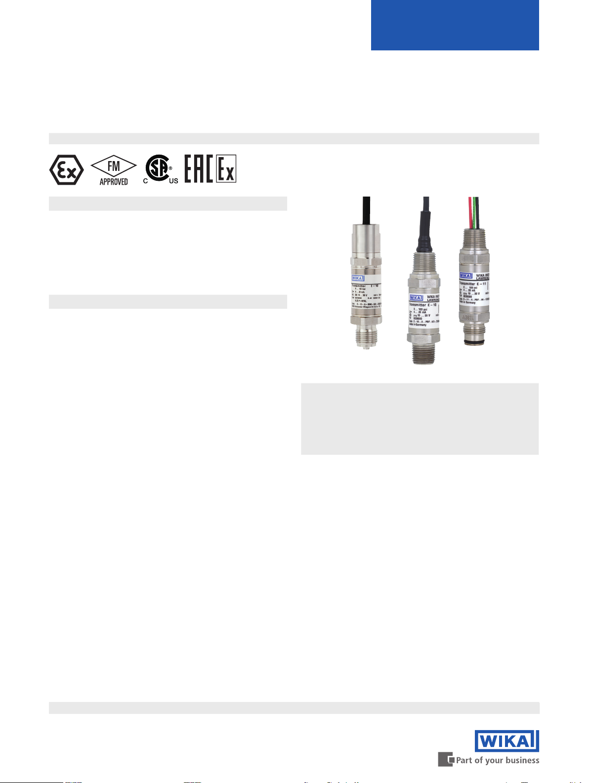
Fig. left: Model E-10, standard version
(ATEX, IECEx)
Fig. centre: Model E-10, standard version
(FM, CSA)
Fig. right: Model E-11, with ush diaphragm
(FM, CSA)
of ≤ 0.5 % can be ensured. Temperature compensation
guarantees accuracy and long-term stability, even with strong
uctuations in the ambient temperature.
The models E-10 and E-11 are suitable for sour gas
applications and feature particularly high resistance against
sulphide stress cracking when in contact with sulphurous
gases.
The pressure transmitters are approved as “explosionproof”
for class I, II, III, div. 1 hazardous areas to FM and CSA as
well as “ameproof” for II 2G Ex db IIC T6...T1 Gb to ATEX
and IECEx.
WIKA data sheet PE 81.27
Data sheets showing similar products:
High-quality pressure transmitter for general industrial applications; model S-20; see data sheet PE 81.61
Pressure transmitter for viscous and particle-laden media; model S-11; see data sheet PE 81.02
Intrinsically safe pressure transmitter; model IS-2x; see data sheet PE 81.50
Non-incendive pressure transmitter; model N-1x; see data sheet PE 81.26
∙ 08/2019
Page 1 of 7
Page 2

Measuring ranges
Gauge pressure
bar Measuring range 0 ... 0.4 0 ... 0.6 0 ... 1 0 ... 1.6 0 ... 2.5 0 ... 4
Overpressure limit 3.1 3.1 3.1 6.2 6.2 14
Measuring range 0 ... 6 0 ... 10 0 ... 16 0 ... 25 0 ... 40 0 ... 60
Overpressure limit 31 31 62 62 80 120
Measuring range 0 ... 100 0 ... 160 0 ... 250 0 ... 400 0 ... 600
2)
Overpressure limit 200 320 500 800 1,200 1,500
psi Measuring range 0 ... 5 0 ... 10 0 ... 15 0 ... 25 0 ... 30 0 ... 60
Overpressure limit 45 45 45 89 89 203
Measuring range 0 ... 100 0 .. 160 0 ... 200 0 ... 250 0 ... 300 0 ... 500
Overpressure limit 449 899 899 899 899 1,160
Measuring range 0 ... 600 0 ... 750 0 ... 1,000 0 ... 1,500 0 ... 2,000 0 ... 3,000
Overpressure limit 1,160 1,740 1,740 2,900 4,600 7,200
Measuring range 0 ... 5,000 0 ... 8,000
2)
0 ... 10,000
1)
0 ... 15,000
1)
Overpressure limit 11,600 17,400 17,400 21,750
1) Measuring range not for model E-11.
2) Measuring range not for model E-11 with FM and CSA approval
Absolute pressure
bar Measuring range 0 ... 0.4 0 ... 0.6 0 ... 1 0 ... 1.6 0 ... 2.5
Overpressure limit 2 4 5 10 10
Measuring range 0 ... 4 0 ... 6 0 ... 10 0 ... 16
Overpressure limit 17 35 35 80
psi Measuring range 0 ... 15 0 ... 25 0 ... 30 0 ... 60 0 ... 100
Overpressure limit 72 145 145 240 500
0 ... 1,000
1)
Vacuum and +/- measuring range
bar Measuring range -1 ... 0 -1 ... +0.6 -1 ... +1.5 -1 ... +3 -1 ... +5
Overpressure limit 2 4 5 10 17
Measuring range -1 ... +9 -1 ... +15 -1 ... +25
Overpressure limit 35 35 50
psi Measuring range -30 inHg ... 0 -30 inHg ... +30 -30 inHg ... +60 -30 inHg ... +100 -30 inHg ... +200
Overpressure limit 29 145 240 500 1,160
Measuring range -30 inHg ... +300
Overpressure limit 1,160
The given measuring ranges are also available in mbar, MPa, kPa, kg/cm2 and further units.
Vacuum tightness
Yes
WIKA data sheet PE 81.27 ∙ 08/2019 Page 2 of 7
Page 3

Output signals
Accuracy specications
Signal type Signal
Current (2-wire) 4 ... 20 mA
Voltage (3-wire) DC 0 ... 5 V
DC 0.5 ... 4.5 V
DC 1 ... 5 V (low power)
DC 0 ... 10 V
Load in Ω
4 ... 20 mA: ≤ (power supply - 10 V) / 0.02 A
DC 0 ... 5 V: > maximum output signal / 1 mA
DC 0.5 ... 4.5 V: > 100k
DC 1 ... 5 V > 100k
DC 0 ... 10 V: > maximum output signal / 1 mA
Voltage supply
Power supply
The power supply depends on the selected output signal.
4 ... 20 mA: DC 10 ... 30 V
DC 0 ... 5 V: DC 10 ... 30 V
DC 0.5 ... 4.5 V: DC 5 ... 30 V
DC 1 ... 5 V: DC 6 ... 30 V
DC 0 ... 10 V: DC 14 ... 30 V
Accuracy at reference conditions
0.5 % of span
Including non-linearity, hysteresis, zero oset and end value
deviation (corresponds to measured error per IEC 61298-2).
Non-linearity (per IEC 61298-2)
≤ 0.2 % of span (BFSL)
Non-repeatability
≤ 0.1 % of span
Temperature error in range 0 ... 80 °C [32 ... 176 °F]
Mean temperature coecient of zero point:
≤ 0.2 % of span/10 K
Mean temperature coecient of span:
≤ 0.2 % of span/10 K
Settling time
≤ 2 ms
≤ 10 ms (at medium temperature < -30 °C [-22 °F] and
measuring range ≤ 0 ... 25 bar; for model E-11)
Long-term stability
≤ 0.2 % of span/year
Max. power consumption
1 W
Reference conditions (per IEC 61298-1)
Temperature
15 ... 25 °C [59 ... 77 °F]
Atmospheric pressure
860 ... 1,060 mbar
Humidity
45 ... 75 % r. h.
Power supply
DC 24 V
Mounting position
Calibrated in vertical mounting position with process
connection facing downwards.
For the use in in hydrogen applications, please observe
technical information IN 00.40 on www.wika.com regarding
long-term stability.
WIKA data sheet PE 81.27 ∙ 08/2019 Page 3 of 7
Page 4

Operating conditions
Process connections
Ingress protection (per IEC 60529)
IP67 (NEMA 4x)
Vibration resistance (per IEC 60068-2-6)
20 g
10 g (for variant ½ NPT male conduit, with potted cable outlet)
Shock resistance (per IEC 60068-2-27)
1,000 g (mechanical shock)
100 g (for variant ½ NPT male conduit, with potted cable
outlet)
Permissible temperature ranges
■
for instruments per ATEX and IECEx
Ambient and medium:
T6: -40 ... +60 °C
T5: -40 ... +75 °C
T4: -40 ... +102 °C
T6: -40 ... +140 °F
T5: -40 ... +167 °F
T4: -40 ... +215 °F
Storage:
-40 ... +102 °C -40 ... +215 °F
-40 °C [-40 °F] only valid when no sealing is used.
Sealings from NBR only admissible to -30 °C [-22 °F].
Sealings from FPM/FKM only admissible to -15 °C [5 °F].
■
for instruments per FM, CSA
Ambient and medium:
T6: -40 ... +60 °C
T4: -40 ... +105 °C
T6: -40 ... +140 °F
T4: -40 ... +221 °F
Storage:
-40 ... +105 °C -40 ... +221 °F
-40 °C [-40 °F] only valid when no sealing is used.
Sealings from NBR only admissible to -30 °C [-22 °F].
Sealings from FPM/FKM only admissible to -15 °C [5 °F].
Process connections for model E-10
Process connection per Thread size
DIN 3852-E
EN 837 G ¼ B
ANSI/ASME B1.20.1 ⅛ NPT
1) Max. ambient and medium temperature range, sealing for process connection:
-30 ... +100 °C
1)
G ¼ A
G ¼ female
G ½ B
¼ NPT
¼ NPT female
½ NPT
Process connections for model E-11
For the ush process connections there is a limited selection
of measuring ranges
Process
connection per
Thread size
Available for
measuring
ranges
- G ½ B ush 0 ... 2.5 to
0 ... 600 bar
- G 1 B ush 0 ... 0.4 to
0 ... 1.6 bar
Sealing for model E-11
Sealing for model E-11
Standard NBR
Option 1 FPM/FKM
Option 2 EPDM
Sealing material restrictions for G ½ B ush process
connection
Explosion protection
ATEX and IECEx
II 2G Ex db IIC T6...T1 Gb (KEMA 05 ATEX 2240 X)
Ex db IIC T6...T1 Gb (IECEx DEK 15.0048X)
FM
XP / I / 1ABCD / T6, T4
Material Max. measuring range
T = -40 °C
[-40°F]
NBR - 600 bar 600 bar 600 bar
FPM/FKM - - 400 bar 400 bar
EPDM 200 bar 200 bar 200 bar 200 bar
T = ambient and medium temperature
T = -30 °C
[-22 °F]
T = -15 °C
[5 °F]
T = 105 °C
[221 °F]
DIP / II, III / 1 EFG / T6, T4 type 4
CSA
Class I, division 1, groups A, B, C and D
Class II, division 1, groups E, F and G
Class III, division 1
Type 4X
WIKA data sheet PE 81.27 ∙ 08/2019 Page 4 of 7
Page 5

Materials
Wetted parts
■
Stainless steel (additionally Elgiloy for model E-10 with
measuring range > 0 ... 25 bar, NACE-compliant)
■
For sealing materials see “Process connections”
Where the medium is hydrogen, contact the manufacturer.
Non-wetted parts
Case from stainless steel
For cable see “Electrical connections”
Internal pressure transmission medium
Synthetic oil (no pressure transmission medium for
model E-10 with measuring range > 0 ... 25 bar)
For other materials see WIKA diaphragm seal programme
Electrical connections
Electrical connection Wire cross-
section
½ NPT male conduit, with potted cable outlet
(ATEX and IECEx approval)
½ NPT conduit male, with cable outlet
(FM and CSA approval)
½ NPT male conduit with potted cable leads
(FM and CSA approval)
3 x 0.5 mm²
AWG20
3 x 0.56 mm²
AWG20
3 x 0.5 mm²
AWG20
Short-circuit resistance
S
vs. U
-
+
Reverse polarity protection
U+ vs. U
-
Insulation voltage
DC 500 V
Connection diagrams
½ NPT male conduit, with potted cable outlet
(ATEX and IECEx approval)
2-wire 3-wire
U+ red red
U- black black
S+ - brown
Shield Shield connected to case
Cable diameter Cable lengths Material
6.8 mm [0.27 in] 2 m [6.6 ft]
5 m [16.4 ft]
5.4 mm [0.21 in] up to 9 m [29.5 ft] PVC
3 x 2.6 mm [3 x 0.10 in] up to 9 m [29.5 ft] Polyolen
½ NPT male conduit with potted cable leads
(FM and CSA approval)
2-wire 3-wire
U+ red red
U- black black
S+ - brown
Shield green green
Polyolen
copolymer
½ NPT conduit male, with cable outlet
(FM and CSA approval)
2-wire 3-wire
U+ red red
U- black black
S+ - brown
Shield Shield connected to case
WIKA data sheet PE 81.27 ∙ 08/2019 Page 5 of 7
Page 6

Approvals (option)
Logo Description Country
EC declaration of conformity
■
EMC directive
EN 61326 emission (group 1, class B) and interference immunity (industrial application)
■
Pressure equipment directive
■
ATEX directive, ameproof (Ex d), EN 60079-0, EN 60079-1, EU
IECEx
Hazardous areas
ameproof (Ex d), IEC 60079-0, IEC 60079-1
FM
Hazardous areas
Explosionproof class 3600, class 3615, class 3810, NEMA-250
CSA
■
Safety (e.g. electr. safety, overpressure, ...)
■
Hazardous areas
Class 2258 02, class 2258 82
EAC
■
Electromagnetic compatibility
■
Hazardous areas
CRN
Safety (e.g. electr. safety, overpressure, ...)
Approvals and certicates, see website
European Community
IECEx member states
USA
USA and Canada
Eurasian Economic Community
Canada
Dimensions in mm
½ NPT male conduit with potted cable
outlet (ATEX and IECEx approval)
½ NPT male conduit with cable outlet
(FM and CSA approval)
½ NPT male conduit with potted cable
leads (FM and CSA approval)
WIKA data sheet PE 81.27 ∙ 08/2019 Page 6 of 7
Page 7

Process connections model E-10
G L1
G ¼ B 13 [0.51]
G ½ B 20 [0.79]
G L1 L2 L3 D1
G ¼ female
19.5
[0.77]
13
[0.51]
10
[0.39]
∅17.5
[0.69]
Process connections model E-11
G L1
⅛ NPT 10 [0.39]
¼ NPT 13 [0.51]
½ NPT 19 [0.75]
G L1 L2 D1
¼ NPT female
20
[0.79]
14
[0.55]
∅ 26.5
[1.04]
G L1
G ¼ A 14 [0.55]
G L1 L2 L3 D1
G ½ B
23
[0.90]
20.5
[0.81]
10
[0.39]
Ø 18
[0.71]
G1 L1 L2 L3 D1
G 1 B 23
[0.90]
20,5
[0.81]
10
[0.39]
30
[1.18]
For information on tapped holes and welding sockets, see Technical information
IN 00.14 at www.wika.com
Ordering information
Model / Measuring range / Output signal / Electrical connection / Process connection / Sealing
© 01/2016 WIKA Alexander Wiegand SE & Co. KG, all rights reserved.
The specications given in this document represent the state of engineering at the time of publishing.
We reserve the right to make modications to the specications and materials.
WIKA data sheet PE 81.27 ∙ 08/2019 Page 7 of 7
08/2019 EN
WIKA Alexander Wiegand SE & Co. KG
Alexander-Wiegand-Straße 30
63911 Klingenberg/Germany
Tel. +49 9372 132-0
Fax +49 9372 132-406
info@wika.de
www.wika.de
 Loading...