

WIKA PGT23.063, PGT43.100, APGT43.100, PGT63HP.100, PGT23.100 Operating Instructions Manual
...Page 1
Operating instructions
Betriebsanleitung
Pressure gauges with output signal,
optional for hazardous areas
Manometer mit Ausgangssignal,
optional für explosionsgefährdete Bereiche
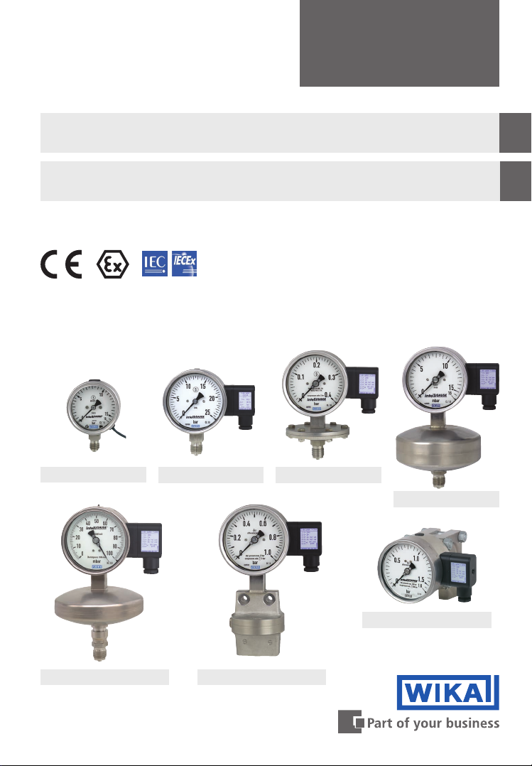
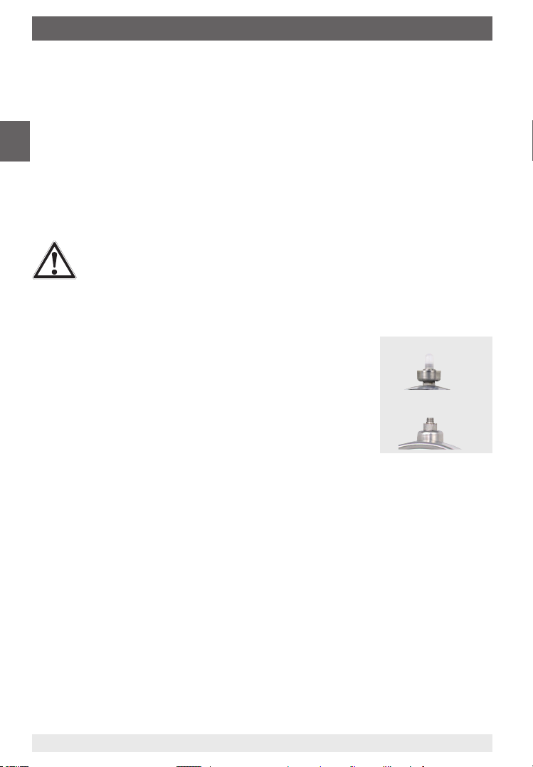
Examples for pressure gauges with output signal
Model PGT23.063
Model PGT23.100 Model PGT43.100
EN
DE
Model PGT63HP.100
Model APGT43.100
Model DPGT43HP.100
Model DPGT43.100
Page 2

Operating instructions for pressure gauges with
EN
output signal, optional for hazardous areas
Page 3 - 32
Betriebsanleitung für Manometer mit Ausgangssi-
DE
gnal, optional für explosionsgefährdete Bereiche
© 07/2019 WIKA Alexander Wiegand SE & Co. KG
All rights reserved. / Alle Rechte vorbehalten.
®
WIKA
is a registered trademark in various countries.
®
WIKA
ist eine geschützte Marke in verschiedenen Ländern.
Prior to starting any work, read the operating instructions!
Keep for later use!
Vor Beginn aller Arbeiten Betriebsanleitung lesen!
Zum späteren Gebrauch aufbewahren!
Seite 33 - 63
2
Pressure gauges with output signal, optional for hazardous areas
11297264.05 07/2019 EN/DE
Page 3

Contents
Contents
1. General information 4
2. Design and function 5
2.1 Overview . . . . . . . . . . . . . . . . . . . . . . . 5
2.2 Description. . . . . . . . . . . . . . . . . . . . . . . 5
2.3 Scope of delivery . . . . . . . . . . . . . . . . . . . . 5
3. Safety 6
3.1 Explanation of symbols . . . . . . . . . . . . . . . . . . 6
3.2 Intended use . . . . . . . . . . . . . . . . . . . . . . 6
3.3 Improper use . . . . . . . . . . . . . . . . . . . . . . 7
3.4 Responsibility of the operator . . . . . . . . . . . . . . . . 7
3.5 Personnel qualification. . . . . . . . . . . . . . . . . . . 8
3.6 Skilled personnel . . . . . . . . . . . . . . . . . . . . 8
3.7 Labelling, safety marks . . . . . . . . . . . . . . . . . . 8
3.8 Ex marking (option) . . . . . . . . . . . . . . . . . . . .10
3.9 Specifications and temperature limits. . . . . . . . . . . . . .10
3.10 Special conditions for safe use (X conditions) . . . . . . . . . . .12
4. Transport, packaging and storage 13
4.1 Transport . . . . . . . . . . . . . . . . . . . . . . .13
4.2 Packaging and storage . . . . . . . . . . . . . . . . . .13
5. Commissioning, operation 14
5.1 Mechanical connection . . . . . . . . . . . . . . . . . .14
5.2 Electrical connection . . . . . . . . . . . . . . . . . . .17
5.3 Zero point setting (not for PGT23.063) . . . . . . . . . . . . .19
5.4 Commissioning . . . . . . . . . . . . . . . . . . . . .20
6. Faults 21
7. Maintenance and cleaning 22
7.1 Maintenance . . . . . . . . . . . . . . . . . . . . . .22
7.2 Cleaning . . . . . . . . . . . . . . . . . . . . . . .23
8. Dismounting, return and disposal 24
8.1 Dismounting . . . . . . . . . . . . . . . . . . . . . .24
8.2 Return . . . . . . . . . . . . . . . . . . . . . . . .24
8.3 Disposal . . . . . . . . . . . . . . . . . . . . . . .25
9. Specications 26
9.1 Electrical connection . . . . . . . . . . . . . . . . . . .26
9.2 Transmitter electronics for non-hazardous areas . . . . . . . . . .27
9.3 Transmitter electronics for hazardous areas . . . . . . . . . . .27
9.4 Pressure gauges with output signal . . . . . . . . . . . . . .28
Annex: EU declaration of conformity 63
EN
Declarations of conformity can be found online at www.wika.com.
11297264.05 07/2019 EN/DE
3Pressure gauges with output signal, optionally for hazardous areas
Page 4

1. General information
1. General information
The contact pressure gauge described in the operating instructions has been designed
and manufactured using state-of-the-art technology. All components are subject to stringent quality and environmental criteria during production. Our management systems are
EN
certied to ISO 9001 and ISO 14001.
These operating instructions contain important information on handling the instrument.
Working safely requires that all safety instructions and work instructions are observed.
Observe the relevant local accident prevention regulations and general safety regulations
for the instrument's range of use.
The operating instructions are part of the product and must be kept in the immediate
vicinity of the instrument and readily accessible to skilled personnel at any time.
Skilled personnel must have carefully read and understood the operating instructions
prior to beginning any work.
The manufacturer's liability is void in the case of any damage caused by using the
product contrary to its intended use, non-compliance with these operating instructions,
assignment of insuciently qualied skilled personnel or unauthorised modications to
the instrument.
The general terms and conditions contained in the sales documentation shall apply.
Subject to technical modications.
Further information:
- Internet address: www.wika.de / www.wika.com
Model Transmitter electronics
for non-hazardous areas
Model Variant
PGT23.063 891.44 1, 3, 4 - - PV 12.03
PGT23.1x0, PGT26.1x0 891.44 1, 3, 4 892.44 2 PV 12.04
PGT43 891.44 1, 3, 4 892.44 2 PV 14.03
PGT43HP 891.44 1, 3, 4 892.44 2 PV 14.07
PGT63HP 891.44 1, 3, 4 892.44 2 PV 16.06
APGT43 891.44 1, 3, 4 892.44 2 PV 15.02
DPGT43 891.44 1, 3, 4 892.44 2 PV 17.05
DPGT43HP 891.44 1, 3, 4 892.44 2 PV 17.13
1) Variant of the output signal
1: 4 … 20 mA, 2-wire, passive, per NAMUR NE 43
2: 4 ... 20 mA, 2-wire, for hazardous areas
3: 0 ... 20 mA, 3-wire
4: 0 ... 10 V, 3-wire
Transmitter electronics
for hazardous areas
1)
Model Variant
For instruments which are additionally tted with switch contact(s), the following operating instructions also apply:
- “Pressure gauges with inductive contact model 831, for hazardous areas”,
article number 14320154
- “Pressure gauges with switch contact model 821, 851 or 830 E”,
article number 14057651
Pressure gauges with output signal, optionally for hazardous areas4
Data
sheet
1)
11297264.05 07/2019 EN/DE
Page 5
2. Design and function
2. Design and function
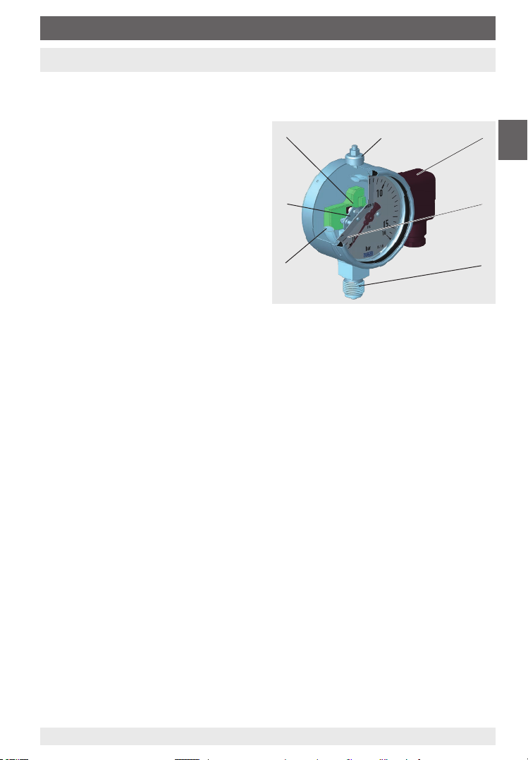
2.1 Overview
Example model PGT23.100, version “S3” per EN 837
Pressure element
Movement
Transmitter electronics
Pressure compensating valve
Electrical connection with cable box
Laminated safety glass
Process connection
EN
2.2 Description
For the instruments described, because of their robustness and ease of use, Bourdon tube,
diaphragm, capsule and corrugated steel measuring elements are widely used. Under the
inuence of pressure, the pressure elements deform within their elastic limits. A mechanical
movement transfers this deformation into a rotational motion. A magnet on the pointer shaft
rotates proportionally to the instrument pointer as a direct linear function of the process
pressure. The angle sensor contained in the transmitter electronics measures the rotational
motion of the magnet in the range 0 ... 270°. The angle change is registered without any
contact and, thus, wear-free and is converted to an analogue output signal via an amplier.
The span of the output signal corresponds to the measuring span on the dial.
Safety version “S3” per EN 837
This version is made up of laminated safety glass, a solid bae wall between measuring
system and dial and a blow-out back. In the event of a failure, the operator is protected at the
front side, as media or components can only be ejected via the back of the case.
Ex version
All instruments, except for the model PGT23.063, are also optionally available in a design for
hazardous areas.
2.3 Scope of delivery
Cross-check scope of delivery with delivery note.
11297264.05 07/2019 EN/DE
5Pressure gauges with output signal, optionally for hazardous areas
Page 6
2. Design and function / 3. Safety
3. Safety
3.1 Explanation of symbols
WARNING!
... indicates a potentially dangerous situation that can result in serious injury or
EN
3.2 Intended use
Pressure gauges with output signal combine a mechanical measuring system with electronic
signal processing and are used to control process values as well as for plant monitoring in
industrial applications. The instrument oers many application possibilities for gaseous and
liquid aggressive media that are not highly viscous or crystallising.
Only use the instrument in applications that lie within its technical performance limits (e.g.
temperature limits, material compatibility, ...).
→ For performance limits see chapter 9 “Specications”.
The instrument has been designed and built solely for the intended use described here, and
may only be used accordingly.
The manufacturer shall not be liable for claims of any type based on operation contrary to
the intended use.
death, if not avoided.
CAUTION!
... indicates a potentially dangerous situation that can result in light injuries or
damage to property or the environment, if not avoided.
DANGER!
... identies hazards caused by electrical power. Should the safety instructions
not be observed, there is a risk of serious or fatal injury.
WARNING!
... indicates a potentially dangerous situation in the hazardous area that results
in serious injury or death, if not avoided.
WARNING!
... indicates a potentially dangerous situation that can result in burns, caused by
hot surfaces or liquids, if not avoided.
Information
... points out useful tips, recommendations and information for ecient and
trouble-free operation.
Pressure gauges with output signal, optionally for hazardous areas6
11297264.05 07/2019 EN/DE
Page 7
3. Safety
3.3 Improper use
WARNING!
Injuries through improper use
Improper use of the instrument can lead to hazardous situations and injuries.
▶
Refrain from unauthorised modications to the instrument.
▶
Do not use the instrument with abrasive or viscous media.
Exceptions are diaphragm pressure gauges (models PGT43 and PGT43HP)
with specially coated diaphragms (abrasive) or versions with open connect-
ing anges (viscous).
Any use beyond or dierent to the intended use is considered as improper use.
3.4 Responsibility of the operator
The instrument is used in the industrial sector. The operator is therefore responsible for legal
obligations regarding safety at work.
The safety instructions within these operating instructions, as well as the safety, accident
prevention and environmental protection regulations for the application area must be
maintained.
The operator is obliged to maintain the product label in a legible condition.
To ensure safe working on the instrument, the operating company must ensure
that suitable rst-aid equipment is available and aid is provided whenever required.
that the operating personnel are regularly instructed in all topics regarding work safety,
rst aid and environmental protection and know the operating instructions and in particular, the safety instructions contained therein.
that the instrument is suitable for the particular application in accordance with its intended
use.
that personal protective equipment is available.
EN
On the wetted parts of the instrument, small residual amounts of the adjustment
medium (e.g. compressed air, water, oil) can adhere from production. With
increased requirements for technical cleanliness, suitability for the application
must be checked by the operator before commissioning.
11297264.05 07/2019 EN/DE
7Pressure gauges with output signal, optionally for hazardous areas
Page 8
3. Safety
3.5 Personnel qualification
WARNING!
Riskofinjuryshouldqualicationbeinsucient!
Improper handling can result in considerable injury and damage to equipment.
The activities described in these operating instructions may only be carried out
EN
3.6 Skilled personnel
Skilled personnel are understood to be personnel who, based on their technical training,
knowledge of measurement and control technology and on their experience and knowledge
of country-specic regulations, current standards and directives, are capable of carrying out
the work described and independently recognising potential hazards.
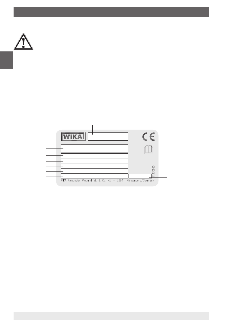
3.7 Labelling, safety marks
Product label Non-Ex version (example PGT23.063)
by skilled personnel who have the qualications described below.
Instrument type
Model + transmitter electronics
Scale range
Output signal
Supply voltage
Case lling
Article number
Date of manufacture (month/year)
Pressure gauges with output signal, optionally for hazardous areas8
11297264.05 07/2019 EN/DE
Page 9
3. Safety
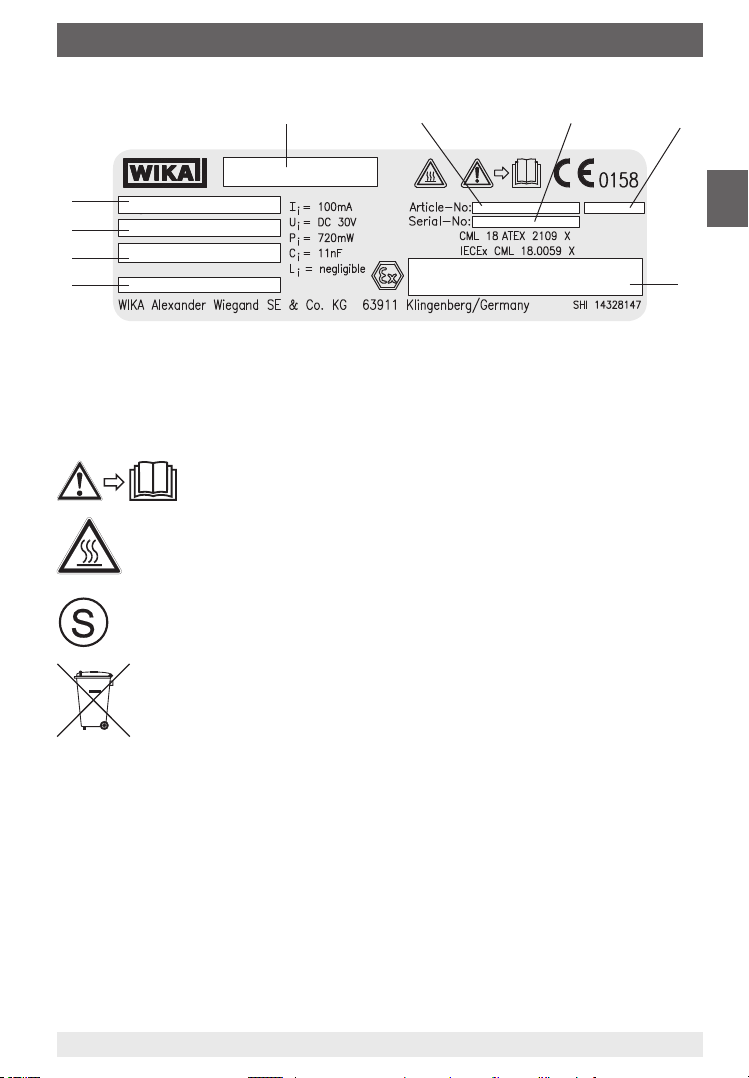
Product label Ex version (example)
Model + transmitter electronics
Article number
Serial number
Date of manufacture (month/year)
Ex marking
Risk of burns!
Potentially dangerous situation caused by hot surfaces.
The instrument bearing this mark is a safety pressure gauge with a solid bae
wall in accordance with EN 837, safety version “S3”.
Do not dispose of with household waste. Ensure a proper disposal in accordance with national regulations.
Case lling
Supply voltage
Output signal
Scale range
Before mounting and commissioning the instrument, ensure you read the
operating instructions!
EN
11297264.05 07/2019 EN/DE
9Pressure gauges with output signal, optionally for hazardous areas
Page 10

3. Safety
3.8 Ex marking (option)
DANGER!
Danger to life due to loss of explosion protection
Non-observance of these instructions and their contents may result in the loss of
explosion protection.
EN
Check whether the classication is suitable for the application. Observe the relevant national
regulations.
Instruments without PTFE lining
ATEX
II 2G Ex ia IIC T6/T5/T4 Gb
II 2D Ex ia IIIB T85°C /T100°C/T135°C Db
Instruments with PTFE lining
Option with models: PGT43, PGT43HP
ATEX
II 2G Ex ia IIB T6/T5/T4 Gb
▶
Observe the safety instructions in this chapter and further explosion protection instructions in these operating instructions.
▶
Observe the information given in the applicable type examination certicate and the relevant country-specic regulations for installation and use in
hazardous areas (e.g. IEC 60079-14, NEC, CEC).
IECEx
IECEx
3.9 Specifications and temperature limits
Ingress protection per IEC/EN 60529
For information on the ingress protection of the respective instrument, see chapter 9 “Speci-
cations”. For the IECEx assessment, IP20 ingress protection was assumed.
Permissible temperature range
For determining the maximum temperature at the instrument, besides the medium
temperature also other inuences such as the ambient temperature and, if applicable, the
solar irradiation must be taken into account.
Gas hazardous areas
Required temperature class
(ignition temperature)
T6 -20 ... +45 °C
T5 -20 ... +60 °C
T4 ... T1 -20 ... +60 °C, (+70 °C optional)
Permissible temperature range at the instrument
Pressure gauges with output signal, optionally for hazardous areas10
11297264.05 07/2019 EN/DE
Page 11

3. Safety
T-Ref
T-Ref
Dust hazardous areas
Maximum surface temperature Permissible temperature range at the instru-
ment
T85°C -20 ... +45 °C
T100°C -20 ... +60 °C
T135°C -20 ... +60 °C, (+70 °C optional)
The installation should be made in such a way that the temperature range of the instrument,
also considering the eects of convection and thermal radiation, neither exceeds nor falls
below the permissible limits.
The permissible temperature ranges must not be exceeded at the instrument either. If necessary, measures for cooling (e.g. syphon, instrumentation valve) have to be taken.
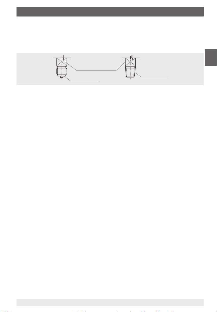
Pressure gauge Dierential pressure gauge
EN
Compliance with the permissible temperature range during operation must be ensured by
the operator by means of temperature measurement(s) at “T-Ref” within the shown hatched
area(s).
11297264.05 07/2019 EN/DE
11Pressure gauges with output signal, optionally for hazardous areas
Page 12

3. Safety
3.10 Special conditions for safe use (X conditions)
i. The temperature class and permitted maximum ambient temperature, are dependent
upon the options tted within the equipment and may not be marked on the equipment
label. The user shall refer to this certicate and to the equipment instructions for details of
the applicable temperature class and ambient temperature range.
ii. The user shall consider that heat may be transferred along the measurement probe and
EN
the equipment shall not exceed the maximum permitted ambient temperature. For further
information, refer to the user instructions.
iii. Models which incorporate a PTFE lining may be marked for use in Group IIB only. The
user shall ensure that such models marked as such are not used in Group IIC Gas nor
Group III dust hazardous areas.
iv. Models which incorporate a PTFE lining may be marked for use in Group IIC gas and
Group IIIB dust hazardous area. Such models also incorporate a warning label advising
the user of a potential electro-static hazard within the process connection area. The user
shall take all necessary precautions to mitigate the risk of electro-static discharge within
the process connection.
v. The equipment may incorporate an integral cable. The user shall ensure that, when
installed, the cable is xed in place and is protected from mechanical damage.
vi. For Group III applications, under certain extreme circumstances, the non-metallic coating
of the enclosure of this equipment may generate an ignition-capable level of electrostatic
charge. Therefore, the equipment shall not be installed in a location where the external
conditions are conducive to the build-up of electrostatic charge on such surfaces. The
user/installer shall implement precautions to prevent the build-up of electrostatic charge,
e.g. locate the equipment where a charge-generating mechanism (such as wind-blown
dust) is unlikely to be present and clean with a damp cloth.
Pressure gauges with output signal, optionally for hazardous areas12
11297264.05 07/2019 EN/DE
Page 13

4. Transport, packaging
4. Transport, packaging and storage
4.1 Transport
Check the instrument for any damage that may have been caused by transport.
Obvious damage must be reported immediately.
CAUTION!
Damage through improper transport
With improper transport, a high level of damage to property can occur.
▶
When unloading packed goods upon delivery as well as during internal transport, proceed carefully and observe the symbols on the packaging.
▶
With internal transport, observe the instructions in chapter 4.2 “Packaging
and storage”.
4.2 Packaging and storage
Do not remove packaging until just before mounting.
Keep the packaging as it will provide optimum protection during transport (e.g. change in
installation site, sending for repair).
Permissible conditions at the place of storage:
Storage temperature: -20 ... +70 °C
Avoid exposure to the following factors:
Direct sunlight or proximity to hot objects
Mechanical vibration, mechanical shock (putting it down hard)
Soot, vapour, dust and corrosive gases
Hazardous environments, ammable atmospheres
EN
Store the instrument in its original packaging in a location that fulls the conditions listed
above.
11297264.05 07/2019 EN/DE
13Pressure gauges with output signal, optionally for hazardous areas
Page 14
5. Commissioning, operation
5. Commissioning, operation
Personnel: Skilled personnel
Before installation, commissioning and operation, ensure that the appropriate instrument has
been selected in terms of scale range, design and specic measuring conditions.
EN
WARNING!
Physical injuries and damage to property and the environment caused by
hazardous media
Upon contact with hazardous media (e.g. with ammable or toxic substances),
harmful media (e.g. corrosive, toxic, carcinogenic, radioactive), there is a danger of
physical injuries and damage to property and the environment.
Should a failure occur, aggressive media with extremely high temperature and
under high pressure may be present at the instrument.
▶
For these media, in addition to all standard regulations, the appropriate existing codes or regulations must also be followed.
▶
Wear the requisite protective equipment.
WARNING!
Physical injuries and damage to property and the environment caused by
media escaping under high pressure
With the pressurisation of the instrument, as a result of poor sealing of the
process connection, media under high pressure can escape.
Due to the high energy of the media that can escape in the event of a failure, the
possibility of physical injuries and damage to property exists.
▶
The sealing of the process connection must be carried out expertly and
checked for leak tightness.
5.1 Mechanical connection
In accordance with the general technical regulations for pressure gauges (e.g. EN 837-2
“Selection and installation recommendations for pressure gauges”).
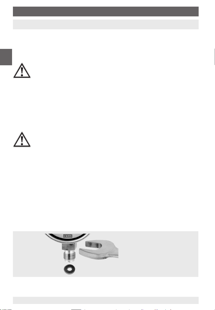
When screwing the instruments in, the force required for sealing must not be applied through
the case, but only through the spanner ats provided for this purpose, and using a suitable
tool.
Installation with open-ended
spanner
For parallel threads, use at gaskets, lens-type sealing rings or WIKA prole sealings at the
sealing face . With tapered threads (e.g. NPT threads), sealing is made in the threads ,
Pressure gauges with output signal, optionally for hazardous areas14
11297264.05 07/2019 EN/DE
Page 15
5. Commissioning, operation
using a suitable sealing material (EN 837-2).
The tightening torque depends on the sealing used. In order to orientate the measuring
instrument so that it can be read as well as possible, a connection with LH-RH union or
union nut should be used. When a blow-out device is tted to an instrument, it must be
protected against being blocked by debris and dirt.
Spanner ats
Sealing face
Installation
Nominal position per EN 837-3 / 9.6.6 gure 7: 90° ( ⊥ )
Process connection lower mount
With lled versions the vent valve at the top of the case must be opened before commis-
sioning!
For outdoor applications, the selected installation location has to be suitable for the
specied ingress protection, so that the instrument is not exposed to impermissible
weather conditions.
In order to avoid any additional heating, the instruments must not be exposed to direct
solar irradiation while in operation!
To ensure that the pressure can be safely vented in the case of failure, due to the
blow-out back, a minimum distance of 20 mm from any object must be maintained.
Sealing in the thread
EN
Requirements for the installation point
If the line to the measuring instrument is not adequately stable, an instrument mounting
bracket should be used for fastening. If vibrations cannot be avoided by means of suitable
installation, lled instruments should be used. The instruments should be protected against
coarse dirt and wide uctuations in ambient temperature.
Permissible vibration load at the installation site
The instruments should always be installed in locations free from vibration. If necessary,
it is possible to isolate the instrument from the mounting point, e.g. by installing a exible
connection line between the measuring point and the instrument and mounting the instrument on a suitable bracket.
If this is not possible, the following limit values must not be exceeded:
Frequency range < 150 Hz
Acceleration < 0.5 g (5 m/s
11297264.05 07/2019 EN/DE
2
)
15Pressure gauges with output signal, optionally for hazardous areas
Page 16
5. Commissioning, operation
Test connection
In specic applications (e.g. steam boilers) the shut-o devices must have a test connection,
so that the instrument can be tested without being dismounted.
Temperature load
The installation of the instrument should be made in such a way that the permissible operat-
EN
ing temperature, also considering the eects of convection and thermal radiation, neither
exceeds nor falls below the permissible limits. Thus the instrument and the shut-o device
must be protected by suciently long measuring lines or syphons.
The inuence of temperature on the indication and measurement accuracy must be
observed.
WARNING!
The actual maximum surface temperature depends not on the equipment itself,
but mainly on the operating conditions. With gaseous substances, the temperature may increase as a result of compression warming. In these cases it may be
necessary to throttle the rate of change of pressure or reduce the permissible
medium temperature.
Commissioning of pressure compensating valve
Instruments which are tted with a pressure compensating valve
must, following installation, be vented for internal pressure compensation.
Tool: Open-ended spanner SW 9
1. Remove plastic cap
2. Loosen the threaded connection above the valve body
3. Screw the valve body tight, turned through 180°, with ≤ 4.5 Nm
Before commissioning
After commissioning
For information on the ingress protection, see Technical information IN 00.18
Protection of the pressure elements from overload
If the medium is subject to rapid changes in pressure, or pressure surges are expected, then
these must not act directly on the pressure element. The action of the pressure surges must
be dampened, for example with the tting of a throttle section (reduction in cross-section in
the pressure port) or through the addition of an adjustable snubber.
Pressure tapping point
The pressure tapping point should be arranged with as large a bore as possible (≥ 6 mm)
via a shut-o device, so that the pressure tap is not distorted by a ow in the medium. The
measuring line between the pressure tapping points and the instrument should have a large
enough internal diameter to prevent blockage and lag in the pressure transmission.
Measuring line
The measuring lines must be as short as possible and should be arranged without sharp
radii in order to avoid any disruptive time lags. When routing these lines, a steady inclination
of approx. 1:15 is recommended.
Pressure gauges with output signal, optionally for hazardous areas16
11297264.05 07/2019 EN/DE
Page 17
5. Commissioning, operation
The measuring line should be designed and installed so that the loads occurring due to
expansion, vibration and thermal eects can be absorbed. With gaseous media, a drain
should be provided at the lowest point; with liquid media, a vent should be provided at the
highest point.
The measuring instruments must be mounted in the common mounting position per EN
837-1, with a max. permissible incline of 5° on all sides.
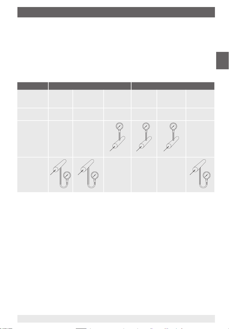
Measuring assemblies
Proven measuring assemblies for various types of media.
Liquid media Gaseous media
Filling of the
measuring
line
Examples conden-
Pressure
gauge above
the tapping
point
Pressure
gauge below
the tapping
point
liquid liquid with
vapour
boiling liquids “liquid
sate
completely
vapourised
gases”
gaseous partially
condensed
(damp)
dry air moist air
ue gases
completely
condensed
steam
EN
5.2 Electrical connection
The electrical connection must only be made by qualied skilled personnel. The instrument
must be connected to the equipotential bonding of the plant.
→ For performance data see chapter 9 „Specications“
Supply voltage non-Ex version
Suitable supply voltage
Model KFA6-STR-1.24.500, AC 115/230 V, for DIN rail, order number: 7305636
Supply voltage Ex version
The instrument must only be used in conjunction with a corresponding Ex repeater power
supply.
Suitable Ex repeater power supply
Model KFD2-STC4-Ex1, DC 20 ... 35 V, for DIN rail, order number: 2341268
11297264.05 07/2019 EN/DE
17Pressure gauges with output signal, optionally for hazardous areas
Page 18
5. Commissioning, operation
Safety instructions for installation
Install instruments in accordance with the manufacturer's instructions and the valid stand-
ards and regulations.
Only connect circuits with the same voltage and type of protection to the connecting
EN
cables of the instrument.
Size the connecting cables for the largest current strength in the circuits and ensure
sucient UV resistance and mechanical stability.
With exible connecting cables, use isolated end splices. Max. permissible conductor
cross-section 1.5 mm².
Connecting cables must be suited to the ambient temperature range of the application.
The connecting cables must also be suitable for the supplied cable gland (for diameter
range, see below).
Seal the cable entry with the appropriate approved cable glands.
Install the connection cables securely.
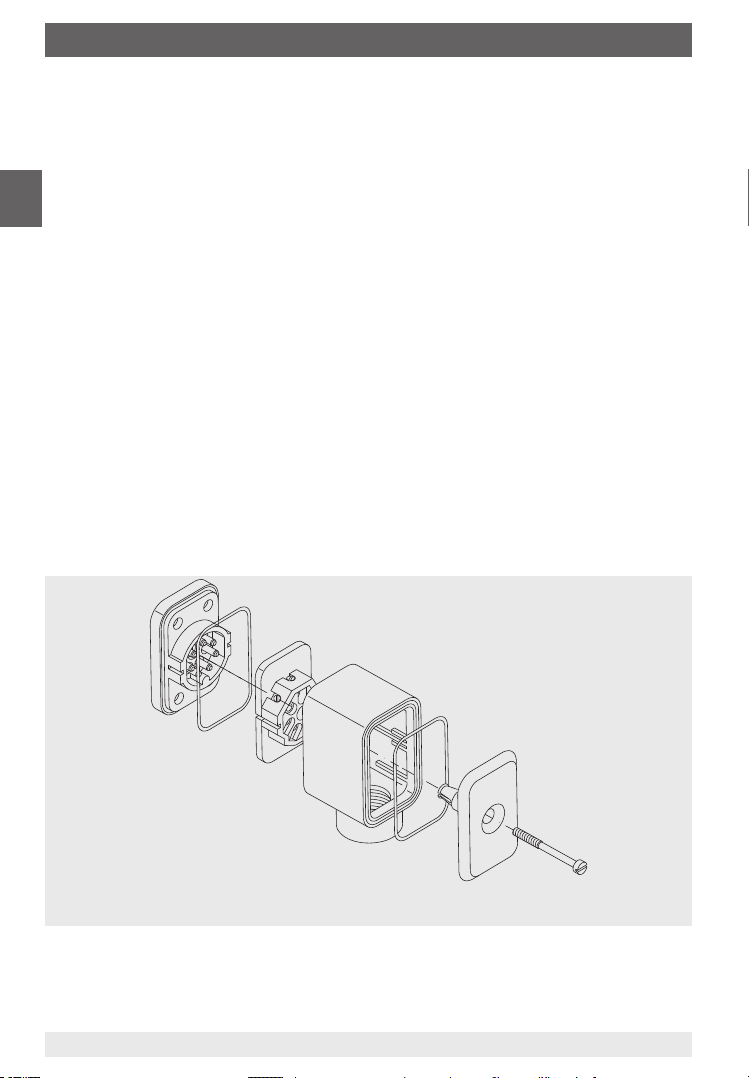
Dismounting cable socket
The cable socket is pretted and must be dismantled as described below.
Only use cable with a diameter of
7 ... 13 mm
Screw
Cable cover cap
Cable cover
Socket insert
Cable socket baseplate
Sealings
Pressure gauges with output signal, optionally for hazardous areas18
11297264.05 07/2019 EN/DE
Page 19
5. Commissioning, operation
Fully loosen the screws on the cable cover cap with a slotted screwdriver (0.6 x 3.5 mm)
and remove them.
Pull the cable cover, along with the socket insert, out from the cable socket baseplate
(joined permanently with the instrument).
Take the cable cover cap and push the socket insert out, downwards, completely through
the cable cap.
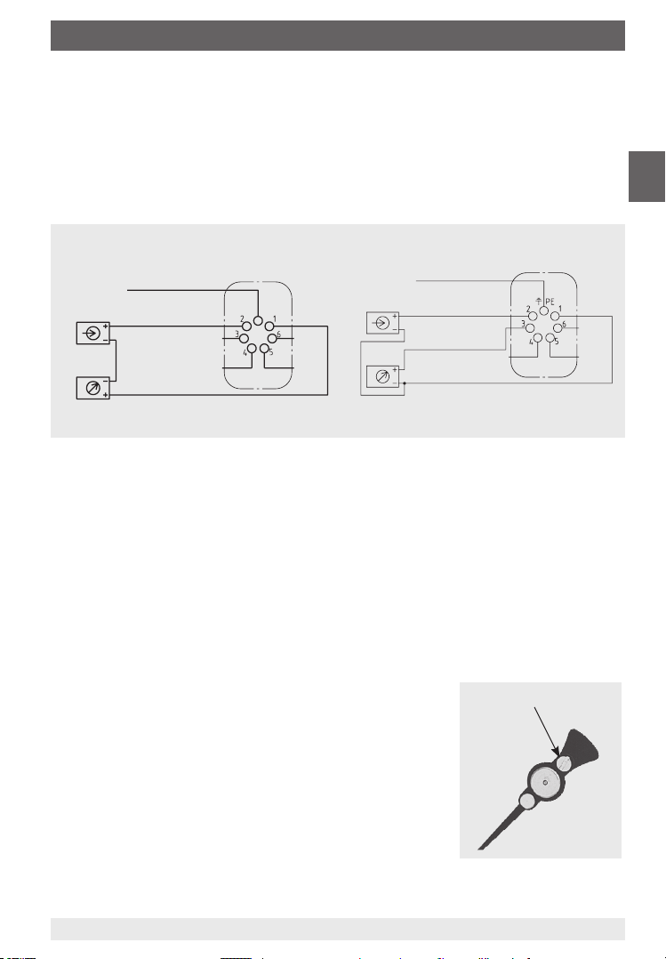
Pin assignment cable socket
EN
2-wire system
e.g. 4 ... 20 mA
Do not use this
terminal
Supply
voltage
Evaluation
(display)
Terminals 3 and 4: For internal use only
Terminals 5 and 6: Reset zero point
U
+/I+
B
+0V/GND
3-wire system:
e.g. 0 ... 20 mA / 0 ... 10 V
Ground, connect-
Supply
voltage
Evaluation
(display)
ed to case
U
+/I+
B
I
out/Uout
+0V/I-
Terminals 4, 5 and 6:
for internal use only
Pin assignment model PGT23.063
Cable Connector Assignment
red Pin 1 U
black Pin 4 0 V/I-
B
+/I+
brown Pin 2 n.c.
- - - Pin 3 n.c
5.3 Zero point setting (not for PGT23.063)
In most cases, the zero point should only be checked and adjusted after the system has
been depressurised. Instruments whose scale does not start at atmospheric pressure the
pressure gauge must be pressurised with the pressure value of the scale start. With dierential pressure gauges, the setting of the zero point should be made by opening the pressure
equalisation valve under static load.
Slotted screw
Mechanical zero point
If there is a deviation from the zero point (in depressurised
condition), the zero point setting can be carried out via the builtin adjustable pointer. For this, remove the bayonet ring including
the window and the seal from the case.
By turning the slotted screw of the adjustable pointer, a mechanical zero point setting can be carried out.
11297264.05 07/2019 EN/DE
19Pressure gauges with output signal, optionally for hazardous areas
Page 20

5. Commissioning, operation
Electrical zero point
If the mechanical zero point has been altered via the adjustable pointer, the electrical zero
point must be matched to the mechanical one. To do this, apply the pressure value of the
scale start. The scale start corresponds to the smallest electrical signal (depending on the
variant either 0 mA, 4 mA or 0 V).
EN
With a small piece of stranded wire (maximum permissible resistance 30 Ω), stripped at both
ends, bridge terminals 5 and 6 on the socket insert.
Installation cable socket
Connect the socket insert to the cable cover and assemble the cable cover cap with the
sealing and screw (see cable socket drawing).
Insert the assembly, which has just been assembled, onto the cable socket baseplate
with sealing.
Screw the screws on the cable cover cap in fully with a slotted screwdriver (0.6 x 3.5 mm).
In order that the ingress protection is maintained, the seals must be retted.
Store zero point in transmitter electronics
After switching on the supply voltage, within a max. 30 seconds, the new zero point will
be saved in the transmitter electronics. As a check, during this time, a current increase to
9.5 mA can be measured in the current loop on a display unit (e.g. ammeter).
Removing the terminal bridge
Switch o supply voltage and display unit.
Carry out the “Dismounting cable socket” described above.
Remove the stranded wire for bridging terminals 5 and 6 from the socket insert.
Carry out the “Installation cable socket” described above.
The electrical output signal will once more match the display of the mechanical pointer.
Close all valves opened for the zero point setting again.
5.4 Commissioning
Pressure surges must be avoided at all costs, open the shut-o valves slowly.
Pressure gauges with output signal, optionally for hazardous areas20
11297264.05 07/2019 EN/DE
Page 21
6. Faults
6. Faults
DANGER!
Danger to life from explosion
Through working in ammable atmospheres, there is a risk of explosion which
can cause death.
▶
Only rectify faults in non-ammable atmospheres!
CAUTION!
Physical injuries and damage to property and the environment
If faults cannot be eliminated by means of the listed measures, the instrument
must be taken out of operation immediately.
▶
Ensure that pressure or signal is no longer present and protect against
accidental commissioning.
▶
Contact the manufacturer.
▶
If a return is needed, please follow the instructions given in chapter 8.2
“Return”.
WARNING!
Physical injuries and damage to property and the environment caused by
hazardous media
Upon contact with hazardous media (e.g. oxygen, acetylene, ammable or toxic
substances), harmful media (e.g. corrosive, toxic, carcinogenic, radioactive),
and also with refrigeration plants and compressors, there is a danger of physical
injuries and damage to property and the environment.
Should a failure occur, aggressive media with extremely high temperature and
under high pressure or vacuum may be present at the instrument.
▶
For these media, in addition to all standard regulations, the appropriate existing codes or regulations must also be followed.
▶
Wear the requisite protective equipment.
EN
For contact details see chapter 1 “General information” or the back page of the
operating instructions.
11297264.05 07/2019 EN/DE
21Pressure gauges with output signal, optionally for hazardous areas
Page 22

6. Faults / 7. Maintenance and cleaning
Faults Causes Measures
No output signal. Insucient supply voltage or cable
EN
Constant output signal
upon change in pressure.
Too high, constant output
signal upon change in
pressure.
Signal span too small. Insucient supply voltage. Check voltage supply and
Zero point signal too low or
too high.
break.
Wrong pin assignment. Check pin assignment.
Defective transmitter electronics due
to overvoltage.
Pressure port blocked at process
connection.
Supply voltage connected the wrong
way. (I = ca. 4.5 mA).
Defective transmitter electronics Replace instrument.
Bridge on terminals 5 and 6 not
removed (I = approx. 9.5 mA).
Defective transmitter electronics due
to overvoltage.
Load too high. Maintain permissible load.
Zero point maladjusted. See chapter 5.3. “Zero point
Zero point maladjusted. See chapter 5.3. “Zero point
For the exchange of the instrument chapters 8 “Dismounting, return and disposal” and 5
“Commissioning, operation” must be observed.
Check voltage supply and
cables.
Clean pressure port at process connection
Check pin assignment.
Remove the terminal bridge.
See chapter 5.3. “Zero point
setting”.
Replace instrument.
cables.
setting”.
setting”.
7. Maintenance and cleaning
7.1 Maintenance
The instruments are maintenance-free.
The indicator and switching function should be checked once or twice every year. For this
the instrument must be disconnected from the process to check with a pressure testing
device.
Testingoflledinstruments
For lled instruments, the level must be checked once or twice every year.
The liquid level must not drop below 75 % of the instrument diameter.
Pressure gauges with output signal, optionally for hazardous areas22
11297264.05 07/2019 EN/DE
Page 23

7. Maintenance and cleaning / 8. Dismounting
WARNING!
Dangertolifeduetoimpermissiblelling/rellingoftheinstrumentwith
loss of explosion protection
The lling/relling of instruments by non-authorised personnel leads to a loss of
the explosion protection and can lead to damage to the instrument.
▶
Repair of the instruments may only be carried out by authorised bodies.
▶
If a return is needed, please follow the instructions given in chapter 8.2
“Return”.
Repairs must only be carried out by the manufacturer.
7.2 Cleaning
CAUTION!
Physical injuries and damage to property and the environment
Improper cleaning may lead to physical injuries and damage to property and the
environment. Residual media in the dismounted instrument can result in a risk to
persons, the environment and equipment.
▶
Carry out the cleaning process as described below.
1. Before cleaning, correctly disconnect the instrument from the pressure supply, switch it
o and disconnect it from the mains.
2. Use the requisite protective equipment.
3. Clean the instrument with a moist cloth.
Electrical connections must not come into contact with moisture!
CAUTION!
Damage to the instrument
Improper cleaning may lead to damage to the instrument!
▶
Do not use any aggressive cleaning agents.
▶
Do not use any hard or pointed objects for cleaning.
EN
4. Wash or clean the dismounted instrument, in order to protect persons and the environment from exposure to residual media.
11297264.05 07/2019 EN/DE
23Pressure gauges with output signal, optionally for hazardous areas
Page 24

8. Dismounting, return and disposal
WARNING!
Physical injuries and damage to property and the environment through
residual media
EN
8.1 Dismounting
Residual media in the dismounted instrument can result in a risk to persons, the
environment and equipment.
▶
Wear the requisite protective equipment.
▶
Observe the information in the material safety data sheet for the
corresponding medium.
▶
Wash or clean the dismounted instrument, in order to protect persons and
the environment from exposure to residual media.
WARNING!
Risk of burns
During dismounting there is a risk of dangerously hot media escaping.
▶
Let the instrument cool down suciently before dismounting it!
DANGER!
Danger to life caused by electric current
Upon contact with live parts, there is a direct danger to life.
▶
The dismounting of the instrument may only be carried out by skilled personnel.
▶
Remove the instrument once the system has been isolated from power sources.
WARNING!
Physical injury
When dismounting, there is a danger from aggressive media and high
pressures.
▶
Observe the information in the material safety data sheet for the corresponding medium.
▶
Dismount the instrument when there is no pressure.
If necessary, the measuring line must have strain relief. For diaphragm pressure gauges, the
clamping bolts of the upper and lower ange must not be loosened.
8.2 Return
Strictly observe the following when shipping the instrument:
All instruments delivered to WIKA must be free from any kind of hazardous substances
(acids, bases, solutions, etc.) and must therefore be cleaned before being returned.
Pressure gauges with output signal, optionally for hazardous areas24
11297264.05 07/2019 EN/DE
Page 25

WARNING!
Physical injuries and damage to property and the environment through
residual media
Residual media in the dismounted instrument can result in a risk to
persons, the environment and equipment.
▶
With hazardous substances, include the material safety data sheet for the
corresponding medium.
▶
Clean the instrument, see chapter 7.2 “Cleaning”.
When returning the instrument, use the original packaging or a suitable transport packaging.
Information on returns can be found under the heading “Service” on our local
website.
8.3 Disposal
Incorrect disposal can put the environment at risk. Dispose of instrument components and
packaging materials in an environmentally compatible way and in accordance with the
country-specic waste disposal regulations.
Do not dispose of with household waste. Ensure a proper disposal in accordance with national regulations.
EN
11297264.05 07/2019 EN/DE
25Pressure gauges with output signal, optionally for hazardous areas
Page 26

9. Specifications
9. Specifications
DANGER!
Danger to life due to loss of explosion protection
The non-observance of the instructions for use in hazardous areas can lead to
EN
9.1 Electrical connection
Standard cable socket
Cable socket, tted on the right-hand side of the case.
Material: PA 6, black
Per VDE 0110 insulation group C/250 V
Cable gland M20 x 1.5 (facing downwards) with strain relief
6 screw terminals + PE for conductor cross-section 1.5 mm²
Cable outlet
Cable length 2 m or 5 m, facing downwards and to the right
Material: PVC
the loss of the explosion protection.
▶
Adhere to the following limit values and instructions.
▶
The case contains parts made of non-metallic material, which could be
adversely aected by environmental conditions. It must be ensured that the
non-metallic parts are not damaged as a result of the environmental conditions.
Non-metallic parts of the case
PUR, TPU, PA 6, EPDM, NBR (option), FMQ (option)
Miniature connector
Miniature connector M8 x 1, 4-pin
Pressure gauges with output signal, optionally for hazardous areas26
11297264.05 07/2019 EN/DE
Page 27

9. Specifications
9.2 Transmitter electronics for non-hazardous areas
Model 891.44
Output signal Variant 1: 4 … 20 mA, 2-wire, passive, per NAMUR NE 43
Supply voltage U
Inuenceofsupplyvoltage ≤ 0.1 % of full scale/10 V
Permissible residual ripple of U
Permissible max. load R
Eectofload(variant1+3) ≤ 0.1 % of full scale
Impedance at voltage output 0.5 Ω
Long-term stability of electronics < 0.3 % of full scale per year
Electr. output signal ≤ 1 % of measuring span
Linear error ≤ 1 % of measuring span (terminal method)
Resolution 0.13 % of full scale (10 bit resolution at 360°)
Refresh rate (measuring rate) 600 ms
B
A
9.3 Transmitter electronics for hazardous areas
Model 892.44
Output signal Variant 2: 4 ... 20 mA, 2-wire, for hazardous areas
Supply voltage U
Inuenceofsupplyvoltage ≤ 0.1 % of full scale/10 V
Permissible residual ripple of U
Permissible max. load R
Eectofload ≤ 0.1 % of full scale
Impedance at voltage output 0.5 Ω
Long-term stability of electronics < 0.3 % of full scale per year
Electr. output signal ≤ 1 % of measuring span
Linear error ≤ 1 % of measuring span (terminal method)
Resolution 0.13 % of full scale (10 bit resolution at 360°)
Refresh rate (measuring rate) 600 ms
B
A
Variant 3: 0 ... 20 mA, 3-wire
Variant 4: 0 ... 10 V, 3-wire
Variant 1+3: DC 12 ... 30 V
Variant 4: DC 15 ... 30 V
≤ 10 % ss
B
Variant 1, 3: RA ≤ (UB - 12 V)/0.02 A with RA in Ohm and UB in
Volt, however max. 600 Ω
Variant 4: R
DC 14 ... 30 V
≤ 10 % ss
B
RA ≤ (UB - 12 V)/0.02 A with RA in Ω and UB in V, however max.
600 Ω
= 100 kΩ
A
EN
Safety-related maximum values
Ui Ii Pi Ci Li
DC 30 V 100 mA 720 mW 11 nF negligible
For further information see Annex “EU declaration of conformity”
11297264.05 07/2019 EN/DE
27Pressure gauges with output signal, optionally for hazardous areas
Page 28

9. Specifications
9.4 Pressure gauges with output signal
Model PGT23.063
Pressure limitation
Steady 3/4 x full scale value
Fluctuating 2/3 x full scale value
EN
Short time Full scale value
Temperatureeect When the temperature of the measuring system deviates from
Wetted materials
Process connection, pressure
element
Non-wetted materials
Case, bayonet ring Stainless steel
Movement Brass
Dial Aluminium, white, black lettering
Pointer Aluminium, black
Window Polycarbonate or laminated safety glass
Ingress protection per IEC/EN 60529 IP54; option: IP65
For further specications see data sheet PV 12.03
the reference temperature (+20 °C): max. ±0.8 %/10 K of full
scale value
Stainless steel 316L
Models PGT23.100, PGT23.160, PGT26.100, PGT26.160
Pressure limitation
Steady Full scale value
Fluctuating 0.9 x full scale value
Short time 1.3 x full scale value
Temperatureeect When the temperature of the measuring system deviates from
Wetted materials
Process connection, pressure
element
Non-wetted materials
Case, bayonet ring Stainless steel
Movement Brass
Dial Aluminium, white, black lettering
Instrument pointer Aluminium, black
Pointer Aluminium, red
Window Laminated safety glass
Ingress protection per IEC/EN 60529 IP65
1) Ingress protection IP54 with lower back mount.
For further specications see data sheet PV 12.04
the reference temperature (+20 °C): max. ±0.4 %/10 K of full
scale value
PGT23.100, PGT23.160: Stainless steel 316L
PGT26.100, PGT26.160: Monel
1)
; option: IP66
Pressure gauges with output signal, optionally for hazardous areas28
11297264.05 07/2019 EN/DE
Page 29

9. Specifications
Models PGT43.100, PGT43.160
Pressure limitation
Steady Full scale value
Fluctuating 0.9 x full scale value
Overload safety 5 x full scale value, however max. 40 bar
Temperatureeect When the temperature of the measuring system deviates from
Wetted materials
Process connection with lower
measuring ange
Pressure element ≤ 0.25 bar: Stainless steel 316L
Sealing FPM/FKM
Non-wetted materials
Case, bayonet ring Stainless steel
Movement Brass
Dial Aluminium, white, black lettering
Pointer Aluminium, black
Window Laminated safety glass
Ingress protection per IEC/EN 60529 IP54; option: IP65
For further specications see data sheet PV 14.03
Model PGT43HP
Pressure limitation
Steady Full scale value
Fluctuating 0.9 x full scale value
Overload safety 40, 100 or 400 bar
Temperatureeect When the temperature of the measuring system deviates from
Wetted materials
Process connection with lower
measuring ange
Pressure element ≤ 0.25 bar: Stainless steel 316L
Sealing FPM/FKM
Non-wetted materials
Case, bayonet ring Stainless steel
Movement Brass
Dial Aluminium, white, black lettering
Pointer Aluminium, black
Window Laminated safety glass
Ingress protection per IEC/EN 60529 IP54; option: IP65
For further specications see data sheet PV 14.07
11297264.05 07/2019 EN/DE
the reference temperature (+20 °C): max. ±0.8 %/10 K of full
scale value
Stainless steel 316L
> 0.25 bar: NiCr alloy (Inconel)
the reference temperature (+20 °C): max. ±0.8 %/10 K of full
scale value
Stainless steel 316L
> 0.25 bar: NiCr alloy (Inconel)
EN
29Pressure gauges with output signal, optionally for hazardous areas
Page 30

9. Specifications
Model PGT63HP
Pressure limitation
Steady Full scale value
Fluctuating 0.9 x full scale value
Overload safety 50 x full scale value
Temperatureeect When the temperature of the measuring system deviates from
EN
Wetted materials
Process connection, pressure
element
Sealing PTFE
Non-wetted materials
Case, bayonet ring Stainless steel
Movement Brass
Dial Aluminium, white, black lettering
Pointer Aluminium, black
Window Laminated safety glass
Ingress protection per IEC/EN 60529 IP54
For further specications see data sheet PV 16.06
Model APGT43
Pressure limitation
Steady Full scale value
Fluctuating 0.9 x full scale value
Overload safety at least 1 bar absolute pressure (atmospheric pressure), in
Temperatureeect When the temperature of the measuring system deviates from
Wetted materials
Process connection Stainless steel 316L
Pressure element ≤ 0.25 bar: Stainless steel 316Ti (1.4571)
Non-wetted materials
Case, bayonet ring Stainless steel
Movement Brass
Dial Aluminium, white, black lettering
Pointer Aluminium, black
Window Laminated safety glass
Ingress protection per IEC/EN 60529 IP54; option: IP65
For further specications see data sheet PV 15.02
the reference temperature (+20 °C): max. ±0.6 %/10 K of full
scale value
Stainless steel 316Ti (1.4571)
addition 10 x full scale value, max. 25 bar absolute pressure
the reference temperature (+20 °C): max. ±0.8 %/10 K of full
scale value
> 0.25 bar: NiCr alloy (Inconel)
Pressure gauges with output signal, optionally for hazardous areas30
11297264.05 07/2019 EN/DE
Page 31

9. Specifications
Models DPGT43.100, DPGT43.160
Pressure limitation
Steady Full scale value
Fluctuating 0.9 x full scale value
Overload safety and
max. working pressure
Temperatureeect When the temperature of the measuring system deviates from
Wetted materials
Media chamber with process
connection, venting of the media
chambers, bellows
Pressure element ≤ 0.25 bar: Stainless steel 316L
Non-wetted materials
Case, bayonet ring Stainless steel
Movement Brass
Dial Aluminium, white, black lettering
Pointer Aluminium, black
Window Laminated safety glass
Ingress protection per IEC/EN 60529 IP54; option: IP65
Overload safety and max. working pressure
Scale ranges Overload safety in bar
Either side max.
Standard Option Standard Option
0 ... 16 to 0 ... 40 mbar 2.5 - 2.5 6
0 ... 60 to 0 ... 250 mbar 2.5 6 6 10
0 ... 400 mbar 4 40 25 40
0 ... 0.6 bar 6 40 25 40
0 ... 1 bar 10 40 25 40
0 ... 1.6 bar 16 40 25 40
0 ... 2.5 to 0 ... 25 bar 25 40 25 40
see the following table
the reference temperature (+20 °C): max. ±0.5 %/10 K of full
scale value
Stainless steel 316Ti (1.4571)
> 0.25 bar: NiCr alloy (Inconel)
max. working pressure in bar
(static pressure)
EN
For further specications see data sheet PV 17.05
11297264.05 07/2019 EN/DE
31Pressure gauges with output signal, optionally for hazardous areas
Page 32

9. Specifications
Models DPGT43HP.100, DPGT43HP.160
Pressure limitation
Steady Full scale value
Fluctuating 0.9 x full scale value
Overload safety and
max. working pressure
EN
Temperatureeect When the temperature of the measuring system deviates from
Wetted materials
Media chamber with process
connection, venting of the media
chambers, bellows
Pressure element ≤ 0.25 bar: Stainless steel 316L
Non-wetted materials
System ll uid measuring cell Silicone oil
Case, movement, bayonet ring Stainless steel
Dial Aluminium, white, black lettering
Pointer Aluminium, black
Window Laminated safety glass
Ingress protection per IEC/EN 60529 IP54; option: IP65
For further specications see data sheet PV 17.13
Either side max. 40, 100, 250 or 400 bar
the reference temperature (+20 °C): max. ±0.5 %/10 K of full
scale value
Stainless steel 316Ti (1.4571)
> 0.25 bar: Stainless steel 316L/Inconel
Pressure gauges with output signal, optionally for hazardous areas32
11297264.05 07/2019 EN/DE
Page 33

Inhalt
Inhalt
1. Allgemeines 35
2. Aufbau und Funktion 36
2.1 Überblick . . . . . . . . . . . . . . . . . . . . . . .36
2.2 Beschreibung . . . . . . . . . . . . . . . . . . . . . .36
2.3 Lieferumfang . . . . . . . . . . . . . . . . . . . . . .36
3. Sicherheit 37
3.1 Symbolerklärung. . . . . . . . . . . . . . . . . . . . .37
3.2 Bestimmungsgemäße Verwendung . . . . . . . . . . . . . .37
3.3 Fehlgebrauch . . . . . . . . . . . . . . . . . . . . . .38
3.4 Verantwortung des Betreibers . . . . . . . . . . . . . . . .38
3.5 Personalqualifikation . . . . . . . . . . . . . . . . . . .39
3.6 Fachpersonal . . . . . . . . . . . . . . . . . . . . . .39
3.7 Beschilderung, Sicherheitskennzeichnungen . . . . . . . . . . .39
3.8 Ex-Kennzeichnung (Option) . . . . . . . . . . . . . . . . .41
3.9 Spezifikation und Temperaturgrenzen. . . . . . . . . . . . . .41
3.10 Besondere Bedingungen für die sichere Verwendung (X-Conditions) . . .43
4. Transport, Verpackung und Lagerung 44
4.1 Transport . . . . . . . . . . . . . . . . . . . . . . .44
4.2 Verpackung und Lagerung . . . . . . . . . . . . . . . . .44
5. Inbetriebnahme, Betrieb 45
5.1 Mechanischer Anschluss . . . . . . . . . . . . . . . . . .45
5.2 Elektrischer Anschluss. . . . . . . . . . . . . . . . . . .48
5.3 Nullpunkteinstellung (nicht für PGT23.063) . . . . . . . . . . . .50
5.4 Inbetriebnahme . . . . . . . . . . . . . . . . . . . . .51
6. Störungen 52
7. Wartung und Reinigung 53
7.1 Wartung. . . . . . . . . . . . . . . . . . . . . . . .53
7.2 Reinigung . . . . . . . . . . . . . . . . . . . . . . .54
8. Demontage, Rücksendung und Entsorgung 55
8.1 Demontage . . . . . . . . . . . . . . . . . . . . . .55
8.2 Rücksendung . . . . . . . . . . . . . . . . . . . . . .55
8.3 Entsorgung . . . . . . . . . . . . . . . . . . . . . .56
9. Technische Daten 57
9.1 Elektrischer Anschluss. . . . . . . . . . . . . . . . . . .57
9.2 Transmitterelektronik für Nicht-Ex-Bereiche. . . . . . . . . . . .58
9.3 Transmitterelektronik für Ex-Bereiche . . . . . . . . . . . . . .58
9.4 Manometer mit Ausgangssignal . . . . . . . . . . . . . . .59
Anlage: EU-Konformitätserklärung 63
DE
Konformitätserklärungen nden Sie online unter www.wika.de.
11297264.05 07/2019 EN/DE
33Manometer mit Ausgangssignal, optional für explosionsgefährdete Bereiche
Page 34

1. Allgemeines
1. Allgemeines
Das in der Betriebsanleitung beschriebene Kontaktmanometer wird nach den neuesten
Erkenntnissen konstruiert und gefertigt. Alle Komponenten unterliegen während der Fertigung strengen Qualitäts- und Umweltkriterien. Unsere Managementsysteme sind nach
DE
ISO 9001 und ISO 14001 zertiziert.
Diese Betriebsanleitung gibt wichtige Hinweise zum Umgang mit dem Gerät. Vorausset-
zung für sicheres Arbeiten ist die Einhaltung aller angegebenen Sicherheitshinweise und
Handlungsanweisungen.
Die für den Einsatzbereich des Gerätes geltenden örtlichen Unfallverhütungsvorschriften
und allgemeinen Sicherheitsbestimmungen einhalten.
Die Betriebsanleitung ist Produktbestandteil und muss in unmittelbarer Nähe des
Gerätes für das Fachpersonal jederzeit zugänglich aufbewahrt werden.
Das Fachpersonal muss die Betriebsanleitung vor Beginn aller Arbeiten sorgfältig durch-
gelesen und verstanden haben.
Die Haftung des Herstellers erlischt bei Schäden durch bestimmungswidrige Verwen-
dung, Nichtbeachten dieser Betriebsanleitung, Einsatz ungenügend qualizierten
Fachpersonals sowie eigenmächtiger Veränderung am Gerät.
Es gelten die allgemeinen Geschäftsbedingungen in den Verkaufsunterlagen.
Technische Änderungen vorbehalten.
Weitere Informationen:
- Internet-Adresse: www.wika.de / www.wika.com
Typ Transmitterelektronik für
Nicht-Ex-Bereiche
Typ Variante
PGT23.063 891.44 1, 3, 4 - - PV 12.03
PGT23.1x0, PGT26.1x0 891.44 1, 3, 4 892.44 2 PV 12.04
PGT43 891.44 1, 3, 4 892.44 2 PV 14.03
PGT43HP 891.44 1, 3, 4 892.44 2 PV 14.07
PGT63HP 891.44 1, 3, 4 892.44 2 PV 16.06
APGT43 891.44 1, 3, 4 892.44 2 PV 15.02
DPGT43 891.44 1, 3, 4 892.44 2 PV 17.05
DPGT43HP 891.44 1, 3, 4 892.44 2 PV 17.13
1) Variante des Ausgangssignals
1: 4 … 20 mA, 2-Leiter, passiv, nach NAMUR NE 43
2: 4 ... 20 mA, 2-Leiter, für explosionsgefährdete Bereiche
3: 0 ... 20 mA, 3-Leiter
4: 0 ... 10 V, 3-Leiter
Transmitterelektronik
für Ex-Bereiche
1)
Typ Variante
Für Geräte die zusätzlich mit Schaltkontakte(n) ausgestattet sind, gelten außerdem
folgende Betriebsanleitungen:
- „Manometer mit Induktivkontakt Typ 831, für explosionsgefährdete Bereiche“,
Artikelnummer 14320154
- „Manometer mit Schaltkontakt Typ 821, 851 oder 830 E“, Artikelnummer 14057651
Datenblatt
1)
Manometer mit Ausgangssignal, optional für explosionsgefährdete Bereiche34
11297264.05 07/2019 EN/DE
Page 35

2. Aufbau und Funktion
2. Aufbau und Funktion
2.1 Überblick
Beispiel Typ PGT23.100, Ausführung „S3“ nach EN 837
Messglied
Zeigerwerk
Transmitterelektronik
Druckausgleichsventil
Elektrischer Anschluss mit Kabelbox
Mehrschichten-Sicherheitsglas
Prozessanschluss
DE
2.2 Beschreibung
Für die beschriebenen Geräte werden wegen ihrer Robustheit und einfachen Handhabung
weit verbreitete Rohr-, Platten-, Kapselfeder- und Wellrohrfedermessglieder verwendet. Die
Messglieder verformen sich unter Druckeinuss im elastischen Bereich. Ein mechanisches
Zeigerwerk übeträgt diese Verformung in eine Drehbewegung. Ein auf der Zeigerwelle
aufgesetzter Magnet dreht sich proportional mit dem Instrumentenzeiger in direkter linearer
Abhängigkeit zum Prozessdruck. Der auf der Transmitterelektronik enthaltene Winkelsensor
erfasst die Drehbewegung des Magneten im Bereich von 0 ... 270°. Die Winkeländerung wird
berührungslos und daher verschleißfrei registriert und über einen Verstärker in ein analoges
Ausgangssignal umgesetzt. Die Spanne des Ausgangssignals entspricht der Messspanne
auf dem Zierblatt.
Sicherheitsausführung „S3“ nach EN 837
Diese Ausführung besteht aus Mehrschichten-Sicherheitsglas, einer bruchsicheren
Trennwand zwischen Messsystem und Zierblatt sowie einer ausblasbaren Rückwand. Im
Fehlerfall ist der Bediener an der Frontseite geschützt, da Messstoe und Bauteile nur über
die Rückseite des Gehäuses austreten können.
Ex-Ausführung
Alle Geräte außer Typ PGT23.063 sind optional auch in einer Ausführung für explosionsgefährdete Bereiche lieferbar.
2.3 Lieferumfang
Lieferumfang mit dem Lieferschein abgleichen.
11297264.05 07/2019 EN/DE
35Manometer mit Ausgangssignal, optional für explosionsgefährdete Bereiche
Page 36

2. Aufbau und Funktion / 3. Sicherheit
3. Sicherheit
3.1 Symbolerklärung
WARNUNG!
… weist auf eine möglicherweise gefährliche Situation hin, die zum Tod oder zu
DE
schweren Verletzungen führen kann, wenn sie nicht gemieden wird.
VORSICHT!
... weist auf eine möglicherweise gefährliche Situation hin, die zu geringfügigen
oder leichten Verletzungen bzw. Sach- und Umweltschäden führen kann, wenn
sie nicht gemieden wird.
GEFAHR!
... kennzeichnet Gefährdungen durch elektrischen Strom. Bei Nichtbeachtung
der Sicherheitshinweise besteht die Gefahr schwerer oder tödlicher
Verletzungen.
WARNUNG!
… weist auf eine möglicherweise gefährliche Situation im explosionsgefährdeten Bereich hin, die zum Tod oder zu schweren Verletzungen führt, wenn sie
nicht gemieden wird.
WARNUNG!
... weist auf eine möglicherweise gefährliche Situation hin, die durch heiße
Oberächen oder Flüssigkeiten zu Verbrennungen führen kann, wenn sie nicht
gemieden wird.
Information
… hebt nützliche Tipps und Empfehlungen sowie Informationen für einen ezienten und störungsfreien Betrieb hervor.
3.2 Bestimmungsgemäße Verwendung
Manometer mit Ausgangssignal vereinen mechanisches Messsystem mit elektronischer
Signalverarbeitung und dienen zum Steuern und Regeln von Prozesswerten sowie zur
Anlagenüberwachung in industriellen Anwendungen. Das Gerät bietet viele Anwendungs-
möglichkeiten für gasförmige und üssige, aggressive, nicht hochviskose und nicht kristallisierende Messstoe.
Das Gerät nur in Anwendungen verwenden, die innerhalb seiner technischen Leistungsgrenzen liegen (z. B. Temperaturgrenzen, Materialverträglichkeit, ...).
→ Leistungsgrenzen siehe Kapitel 9 „Technische Daten“.
Das Gerät ist ausschließlich für den hier beschriebenen bestimmungsgemäßen Verwendungszweck konzipiert und konstruiert und darf nur dementsprechend verwendet werden.
Ansprüche jeglicher Art aufgrund von nicht bestimmungsgemäßer Verwendung sind ausgeschlossen.
Manometer mit Ausgangssignal, optional für explosionsgefährdete Bereiche36
11297264.05 07/2019 EN/DE
Page 37

3. Sicherheit
3.3 Fehlgebrauch
WARNUNG!
Verletzungen durch Fehlgebrauch
Fehlgebrauch des Gerätes kann zu gefährlichen Situationen und Verletzungen
führen.
▶
Eigenmächtige Umbauten am Gerät unterlassen.
▶
Gerät nicht für abrasive und viskose Messstoe verwenden.
Ausnahmen hierbei sind Plattenfedermanometer (Typen PGT43, PGT43HP)
mit speziell beschichteten Membranen (abrasiv) oder Ausführungen mit
oenem Anschlussansch (viskos).
Jede über die bestimmungsgemäße Verwendung hinausgehende oder andersartige Benutzung gilt als Fehlgebrauch.
3.4 Verantwortung des Betreibers
Das Gerät wird im gewerblichen Bereich eingesetzt. Der Betreiber unterliegt daher den
gesetzlichen Pichten zur Arbeitssicherheit.
Die Sicherheitshinweise dieser Betriebsanleitung, sowie die für den Einsatzbereich des
Gerätes gültigen Sicherheits-, Unfallverhütungs- und Umweltschutzvorschriften einhalten.
Der Betreiber ist verpichtet das Typenschild lesbar zu halten.
Für ein sicheres Arbeiten am Gerät muss der Betreiber sicherstellen,
dass eine entsprechende Erste-Hilfe-Ausrüstung vorhanden ist und bei Bedarf jederzeit
Hilfe zur Stelle ist.
dass das Bedienpersonal regelmäßig in allen zutreenden Fragen von Arbeitssicherheit,
Erste Hilfe und Umweltschutz unterwiesen wird, sowie die Betriebsanleitung und insbesondere die darin enthaltenen Sicherheitshinweise kennt.
dass das Gerät gemäß der bestimmungsgemäßen Verwendung für den Anwendungsfall
geeignet ist.
dass die persönliche Schutzausrüstung verfügbar ist.
DE
An den messstoberührten Teilen des Gerätes können herstellungsbedingt
geringe Restmengen des Justagemediums (z. B. Druckluft, Wasser, Öl)
anhaften. Bei erhöhten Anforderungen an die technische Sauberkeit muss die
Eignung für den Anwendungsfall vor Inbetriebnahme vom Betreiber geprüft sein.
11297264.05 07/2019 EN/DE
37Manometer mit Ausgangssignal, optional für explosionsgefährdete Bereiche
Page 38

3. Sicherheit
3.5 Personalqualifikation
WARNUNG!
VerletzungsgefahrbeiunzureichenderQualikation!
Unsachgemäßer Umgang kann zu erheblichen Personen- und Sachschäden
führen.
DE
3.6 Fachpersonal
Das Fachpersonal ist aufgrund seiner fachlichen Ausbildung, seiner Kenntnisse der Mess-
und Regelungstechnik und seiner Erfahrungen sowie Kenntnis der landesspezischen
Vorschriften, geltenden Normen und Richtlinien in der Lage, die beschriebenen Arbeiten
auszuführen und mögliche Gefahren selbstständig zu erkennen.
3.7 Beschilderung, Sicherheitskennzeichnungen
Typenschild Nicht-Ex-Ausführung (Beispiel PGT23.063)
Die in dieser Betriebsanleitung beschriebenen Tätigkeiten nur durch Fachperso-
nal nachfolgend beschriebener Qualikation durchführen lassen.
Geräteart
Typ + Transmitterelektronik
Anzeigebereich
Ausgangssignal
Hilfsenergie
Gehäusefüllung
Artikelnummer
Herstellungsdatum (Monat/Jahr)
Manometer mit Ausgangssignal, optional für explosionsgefährdete Bereiche38
11297264.05 07/2019 EN/DE
Page 39

3. Sicherheit
Typenschild Ex-Ausführung (Beispiel)
Typ + Transmitterelektronik
Artikelnummer
Seriennummer
Herstellungsdatum (Monat/Jahr)
Ex-Kennzeichnung
Verbrennungsgefahr!
Möglicherweise gefährliche Situation durch heiße Oberächen.
Das Gerät mit dieser Kennzeichnung ist ein Sicherheitsdruckmessgerät mit
bruchsicherer Trennwand nach EN 837, Sicherheitsausführung „S3“.
Nicht mit dem Hausmüll entsorgen. Für eine geordnete Entsorgung gemäß
nationaler Vorgaben sorgen.
Gehäusefüllung
Hilfsenergie
Ausgangssignal
Anzeigebereich
Vor Montage und Inbetriebnahme des Gerätes unbedingt die Betriebsanleitung lesen!
DE
11297264.05 07/2019 EN/DE
39Manometer mit Ausgangssignal, optional für explosionsgefährdete Bereiche
Page 40

3. Sicherheit
3.8 Ex-Kennzeichnung (Option)
GEFAHR!
Lebensgefahr durch Verlust des Explosionsschutzes
Die Nichtbeachtung dieser Inhalte und Anweisungen kann zum Verlust des
Explosionsschutzes führen.
DE
Überprüfen, ob die Klassizierung für den Einsatzfall geeignet ist. Die jeweiligen nationalen
Vorschriften und Bestimmungen beachten.
Geräte ohne PTFE-Auskleidung
ATEX
II 2G Ex ia IIC T6/T5/T4 Gb
II 2D Ex ia IIIB T85°C /T100°C/T135°C Db
Geräte mit PTFE-Auskleidung
Option bei Typen: PGT43, PGT43HP
ATEX
II 2G Ex ia IIB T6/T5/T4 Gb
▶
Sicherheitshinweise in diesem Kapitel sowie weitere Explosionsschutzhinweise in dieser Betriebsanleitung beachten.
▶
Die Angaben der geltenden Baumusterprüfbescheinigung sowie die jeweiligen landesspezischen Vorschriften zur Installation und Einsatz in explosionsgefährdeten Bereichen (z. B. IEC 60079-14, NEC, CEC) einhalten.
IECEx
IECEx
3.9 Spezifikation und Temperaturgrenzen
Schutzart nach IEC/EN 60529
Informationen zur Schutzart des jeweiligen Gerätes siehe Kapitel 9 „Technische Daten“. Für
die IECEx-Bewertung wurde die Schutzart IP20 angenommen.
Zulässiger Temperaturbereich
Für die Ermittlung der maximalen Temperatur am Gerät sind außer der Messstotemperatur
noch andere Einüsse wie z. B. die Umgebungstemperatur und gegebenenfalls die
Sonneneinstrahlung zu berücksichtigen.
Gasexplosionsgefährdeter Bereich
Geforderte Temperaturklasse
(Zündtemperatur)
T6 -20 ... +45 °C
T5 -20 ... +60 °C
T4 ... T1 -20 ... +60 °C, (+70 °C optional)
Zulässiger Temperaturbereich am Gerät
Manometer mit Ausgangssignal, optional für explosionsgefährdete Bereiche40
11297264.05 07/2019 EN/DE
Page 41

3. Sicherheit
T-Ref
T-Ref
Staubexplosionsgefährdeter Bereich
MaximaleOberächentemperatur Zulässiger Temperaturbereich am Gerät
T85°C -20 ... +45 °C
T100°C -20 ... +60 °C
T135°C -20 ... +60 °C, (+70 °C optional)
Die Montage ist so auszuführen, dass der zulässige Temperaturbereich des Gerätes, auch
unter Berücksichtigung des Einusses von Konvektion und Wärmestrahlung, weder unter-
noch überschritten wird.
Die zulässigen Temperaturbereiche dürfen auch am Gerät nicht überschritten werden.
Gegebenenfalls sind Maßnahmen zur Kühlung (wie z. B. Wassersackrohr, Instrumentierungsventil) zu ergreifen.
Manometer Dierenzdruckmanometer
DE
Die Einhaltung des zulässigen Temperaturbereiches ist vom Betreiber während des Betrie-
bes mit Hilfe von Temperaturmessung(en) bei „T-Ref“ innerhalb der schraerten Fläche(n)
sicherzustellen.
11297264.05 07/2019 EN/DE
41Manometer mit Ausgangssignal, optional für explosionsgefährdete Bereiche
Page 42

3. Sicherheit
3.10 Besondere Bedingungen für die sichere Verwendung (X-Conditions)
i. Die Temperaturklasse und die zulässige maximale Umgebungstemperatur richten
sich nach den im Gerät installierten Optionen und dürfen auf dem Geräte-Schild
nicht angegeben sein. Einzelheiten zur anwendbaren Temperaturklasse und zum
Umgebungstemperaturbereich sind aus dem vorliegenden Zertikat und der Betriebsan-
DE
leitung ersichtlich.
ii. Der Benutzer muss beachten, dass Wärme entlang der Messsonde übertragen werden
kann und darauf achten, dass das Gerät die maximal zulässige Umgebungstemperatur
nicht überschreitet. Näheres ist der Betriebsanleitung zu entnehmen.
iii. Typen mit einer PTFE-Auskleidung dürfen nur für den Einsatz in Gruppe IIB gekennzeich-
net sein. Der Benutzer muss dafür sorgen, dass Typen, die so gekennzeichnet sind, nicht
in gasexplosionsgefährdeten Bereichen der Gruppe IIC oder in staubexplosionsgefährdeten Bereichen der Gruppe III verwendet werden.
iv. Typen mit PTFE-Auskleidung dürfen nur für den Einsatz in gasexplosionsgefährdeten
Bereichen der Gruppe IIC und in staubexplosionsgefährdeten Bereichen der Gruppe IIIB
gekennzeichnet sein. Derartige Typen sind auch mit einem Warnetikett versehen, das
den Benutzer auf eine mögliche elektrostatische Gefährdung innerhalb des Prozessanschlussbereichs hinweist. Der Benutzer muss alle notwendigen Sicherheitsvorkehrungen
ergreifen, damit die Gefahr einer elektrostatischen Entladung innerhalb des Prozessanschlusses minimiert wird.
v. Im Gerät kann ein Kabel integriert sein. Ist dies der Fall, muss der Benutzer dafür sorgen,
dass dieses gut befestigt und gegen mechanische Beschädigung geschützt ist.
vi. Bei Anwendungen der Gruppe III kann die nichtmetallische Beschichtung des Geräte-
gehäuses unter bestimmten extremen Bedingungen eine zündfähige elektrostatische
Ladung erzeugen. Aus diesem Grunde darf das Gerät nicht an einem Ort installiert
werden, an dem durch die äußeren Bedingungen der Aufbau elektrostatischer Ladung
an solchen Oberächen begünstigt wird. Der Benutzer/Installateur muss Vorsichtsmaßnahmen ergreifen, um einen Aufbau elektrostatischer Ladung zu verhindern, indem er
das Gerät z. B. an einem Ort aufstellt, an dem ein ladungserzeugender Mechanismus
(wie z. B. vom Wind verwehter Staub) wenig wahrscheinlich ist, und das Gerät mit einem
feuchten Tuch abwischt.
Manometer mit Ausgangssignal, optional für explosionsgefährdete Bereiche42
11297264.05 07/2019 EN/DE
Page 43

4. Transport, Verpackung
4. Transport, Verpackung und Lagerung
4.1 Transport
Gerät auf eventuell vorhandene Transportschäden untersuchen.
Oensichtliche Schäden unverzüglich mitteilen.
VORSICHT!
Beschädigungen durch unsachgemäßen Transport
Bei unsachgemäßem Transport können Sachschäden in erheblicher Höhe
entstehen.
▶
Beim Abladen der Packstücke bei Anlieferung sowie innerbetrieblichem
Transport vorsichtig vorgehen und die Symbole auf der Verpackung
beachten.
▶
Bei innerbetrieblichem Transport die Hinweise unter Kapitel 4.2 „Verpackung
und Lagerung“ beachten.
4.2 Verpackung und Lagerung
Verpackung erst unmittelbar vor der Montage entfernen.
Die Verpackung aufbewahren, denn diese bietet bei einem Transport einen optimalen Schutz
(z. B. wechselnder Einbauort, Reparatursendung).
Zulässige Bedingungen am Lagerort:
Lagertemperatur: -20 ... +70 °C
FolgendeEinüssevermeiden:
Direktes Sonnenlicht oder Nähe zu heißen Gegenständen
Mechanische Vibration, mechanischer Schock (hartes Aufstellen)
Ruß, Dampf, Staub und korrosive Gase
Explosionsgefährdete Umgebung, entzündliche Atmosphären
DE
Das Gerät in der Originalverpackung an einem Ort lagern, der die oben gelisteten Bedingungen erfüllt.
11297264.05 07/2019 EN/DE
43Manometer mit Ausgangssignal, optional für explosionsgefährdete Bereiche
Page 44

5. Inbetriebnahme, Betrieb
5. Inbetriebnahme, Betrieb
Personal: Fachpersonal
Vor Montage, Inbetriebnahme und Betrieb sicherstellen, dass das richtige Gerät hinsichtlich
Anzeigebereich, Ausführung und spezischen Messbedingungen ausgewählt wurde.
DE
WARNUNG!
Körperverletzungen, Sach- und Umweltschäden durch gefährliche
Messstoe
Bei Kontakt mit gefährlichen Messstoen (z. B. bei brennbaren oder giftigen
Stoen), gesundheitsgefährdenden Messstoen (z. B. ätzend, giftig, krebserregend,
radioaktiv) besteht die Gefahr von Körperverletzungen, Sach- und Umweltschäden.
Am Gerät können im Fehlerfall aggressive Messstoe mit extremer Temperatur
und unter hohem Druck anliegen.
▶
Bei diesen Messstoen müssen über die gesamten allgemeinen Regeln
hinaus die einschlägigen Vorschriften beachtet werden.
▶
Notwendige Schutzausrüstung tragen.
WARNUNG!
Körperverletzungen, Sach- und Umweltschäden durch unter hohem
DruckaustretendeMessstoe
Bei der Druckbeaufschlagung des Gerätes kann aufgrund schlechter Abdich-
tung des Prozessanschlusses Messsto unter hohem Druck entweichen.
Durch die hohe Energie des im Fehlerfall austretenden Messstoes besteht die
Gefahr von Körperverletzungen und Sachschäden.
▶
Die Abdichtung des Prozessanschlusses muss fachgerecht ausgeführt und
auf Dichtheit überprüft werden.
5.1 Mechanischer Anschluss
Entsprechend den allgemeinen technischen Regeln für Manometer (z. B. EN 837-2
„Auswahl- und Einbauempfehlungen für Druckmessgeräte“).
Beim Einschrauben der Geräte darf die zum Abdichten erforderliche Kraft nicht über das
Gehäuse aufgebracht werden, sondern mit geeignetem Werkzeug nur über die dafür
vorgesehenen Schlüsselächen.
Montage mit Gabelschlüssel
Für zylindrische Gewinde sind an der Dichtäche Flachdichtungen, Dichtlinsen oder
WIKA-Proldichtungen einzusetzen. Bei kegeligen Gewinden (z. B. NPT-Gewinde) erfolgt die
Manometer mit Ausgangssignal, optional für explosionsgefährdete Bereiche44
11297264.05 07/2019 EN/DE
Page 45

5. Inbetriebnahme, Betrieb
Abdichtung im Gewinde , mit geeignetem Dichtungswerksto (EN 837-2).
Das Anzugsmoment ist von der eingesetzten Dichtung abhängig. Um das Messgerät in die
Stellung zu bringen, in der es sich am besten ablesen lässt, ist ein Anschluss mit Spann-
mue oder Überwurfmutter zu empfehlen. Sofern ein Gerät eine Entlastungsönung besitzt,
muss diese vor Blockierung durch Geräteteile oder Schmutz geschützt sein.
Schlüsseläche
Dichtäche
Installation
Nennlage nach EN 837-3 / 9.6.6 Bild 7: 90° ( ⊥ )
Prozessanschluss unten
Bei gefüllten Ausführungen muss vor Inbetriebnahme das Entlüftungsventil an der
Oberseite des Gehäuses geönet werden!
Bei Anwendungen im Freien ist ein für die angegebene Schutzart geeigneter Aufstellort
zu wählen, damit das Gerät keinen unzulässigen Witterungseinüssen ausgesetzt ist.
Um zusätzliche Aufheizung zu vermeiden, dürfen die Geräte im Betrieb keiner direkten
Sonneneinstrahlung ausgesetzt werden!
Für eine sichere Druckentlastung im Fehlerfall muss aufgrund der ausblasbaren
Rückwand ein Abstand von mindestens 20 mm zu jedem Gegenstand eingehalten
werden.
Abdichtung im Gewinde
DE
Anforderungen an die Einbaustelle
Ist die Leitung zum Messgerät für eine erschütterungsfreie Anbringung nicht stabil genug,
sollte die Befestigung mittels Messgerätehalterung erfolgen. Können Erschütterungen nicht
durch geeignete Installationen vermieden werden, dann sollten gefüllte Geräte eingesetzt
werden. Die Geräte sind vor grober Verschmutzung und starken Schwankungen der Umgebungstemperatur zu schützen.
Zulässige Schwingungsbelastung am Einbauort
Die Geräte sollten grundsätzlich nur an Stellen ohne Schwingungsbelastung eingebaut
werden. Gegebenenfalls kann z. B. durch eine exible Verbindungsleitung von der Messstelle zum Gerät und die Befestigung über eine Messgerätehalterung eine Entkopplung vom
Einbauort erreicht werden.
Falls dies nicht möglich ist, dürfen folgende Grenzwerte nicht überschritten werden:
Frequenzbereich < 150 Hz
Beschleunigung < 0,5 g (5 m/s
11297264.05 07/2019 EN/DE
2
)
45Manometer mit Ausgangssignal, optional für explosionsgefährdete Bereiche
Page 46

5. Inbetriebnahme, Betrieb
Prüfanschluss
In bestimmten Anwendungsfällen (z. B. Dampfkessel) müssen die Absperrarmaturen einen
Prüfanschluss besitzen, damit das Gerät ohne Ausbau überprüft werden kann.
Temperaturbelastung
Die Anbringung des Gerätes ist so auszuführen, dass die zulässige Betriebstemperatur,
DE
auch unter Berücksichtigung des Einusses von Konvektion und Wärmestrahlung, weder
unter noch überschritten wird. Dazu sind Gerät und Absperrarmatur durch ausreichend
lange Messleitungen oder Wassersackrohre zu schützen.
Der Temperatureinuss auf die Anzeige- bzw. Messgenauigkeit ist zu beachten.
WARNUNG!
Die tatsächliche maximale Oberächentemperatur hängt nicht vom Gerät
selbst ab, sondern hauptsächlich von den Betriebsbedingungen. Bei gasförmi-
gen Stoen kann sich die Temperatur durch Kompressionswärme erhöhen. In
solchen Fällen muss ggf. die Druckänderungsgeschwindigkeit gedrosselt bzw.
die zulässige Messstotemperatur reduziert werden.
Inbetriebnahme Druckausgleichsventil
Geräte, die mit einem Druckausgleichsventil ausgestattet sind,
müssen nach der Installation zur Innendruckkompensation belüftet
werden.
Werkzeug: Gabelschlüssel SW 9
1. Kunststokappe entfernen
2. Verschraubung oberhalb des Ventilkörpers lösen
3. Ventilkörper um 180° gedreht mit ≤ 4,5 Nm festschrauben
Vor Inbetriebnahme
Nach Inbetriebnahme
Informationen zur Schutzart siehe Technische Information IN 00.18
Schutz der Messglieder vor Überlastung
Unterliegt der Messsto schnellen Druckänderungen oder ist mit Druckstößen zu
rechnen, dürfen diese nicht direkt auf das Messglied einwirken. Die Druckstöße müssen
in ihrer Wirkung gedämpft werden, z. B. durch Einbau einer Drosselstrecke (Verringerung
des Querschnittes im Druckkanal) oder durch Vorschaltung einer einstellbaren
Drosselvorrichtung.
Druckentnahmestutzen
Der Druckentnahmestutzen soll mit einer genügend großen Bohrung (≥ 6 mm) möglichst
über ein Absperrorgan so angeordnet werden, dass die Druckentnahme nicht durch eine
Strömung des Messstoes verfälscht wird. Die Messleitung zwischen Druckentnahmestutzen und Gerät soll zur Vermeidung von Verstopfung und Verzögerungen bei der Druckübertragung einen genügend großen Innendurchmesser besitzen.
Messleitung
Die Messleitungen sind möglichst kurz zu halten und ohne scharfe Krümmungen zu verlegen, um das Auftreten störender Verzugzeiten zu vermeiden. Bei der Verlegung wird eine
stetige Neigung von ca. 1:15 empfohlen.
Manometer mit Ausgangssignal, optional für explosionsgefährdete Bereiche46
11297264.05 07/2019 EN/DE
Page 47

5. Inbetriebnahme, Betrieb
Die Messleitung ist so auszuführen und zu montieren, dass sie die auftretenden Belastungen durch Dehnung, Schwingung und Wärmeeinwirkung aufnehmen kann. Bei Gasen als
Messsto ist an der tiefsten Stelle eine Entwässerung, bei üssigen Messstoen an der
höchsten Stelle eine Entlüftung vorzusehen.
Die Messgeräte müssen gemäß EN 837-1 in der üblichen Einbaulage, mit einer max. zulässigen Neigung von 5° zu allen Seiten, montiert werden.
Messanordnungen
Bewährte Messanordnungen für verschiedene Messstoarten.
FlüssigeMessstoe GasförmigeMessstoe
Füllung der
Messleitung
Beispiele Kondensat siedende
Manometer
oberhalb
des Entnahmestutzens
Manometer
unterhalb
des Entnahmestutzens
üssig zum Teil
ausgasend
Flüssigkeiten
vollständig
verdampft
„Flüssiggase“
gas förmig zum Teil
trockene
Luft
kondensiert
(feucht)
feuchte Luft
Rauchgase
vollständig
kondensiert
Wasserdampf
DE
5.2 Elektrischer Anschluss
Der elektrische Anschluss darf nur durch qualiziertes Fachpersonal erfolgen. Das Gerät
muss in den Potentialausgleich der Anlage eingebunden werden.
→ Leistungsdaten siehe Kapitel 9 „Technische Daten“
Hilfsenergie Nicht-Ex-Ausführung
Passende Stromversorgung:
Typ KFA6-STR-1.24.500, AC 115/230 V, für Hutschiene, Bestellnummer: 7305636
Hilfsenergie Ex-Ausführung
Das Gerät darf nur in Verbindung mit einem entsprechenden Ex-Speisetrenner betrieben
werden.
Passender Ex-Speisetrenner:
Typ KFD2-STC4-Ex1, DC 20 ... 35 V, für Hutschiene, Bestellnummer: 2341268
11297264.05 07/2019 EN/DE
47Manometer mit Ausgangssignal, optional für explosionsgefährdete Bereiche
Page 48

5. Inbetriebnahme, Betrieb
Sicherheitshinweise bei Installation
Geräte gemäß Herstellerangaben und den gültigen Normen und Regeln installieren.
An die Anschlussleitungen des Gerätes nur Stromkreise mit gleicher Spannung bzw. von
gleicher Schutzart anschließen.
DE
Anschlussleitungen für die größte Stromstärke in den Stromkreisen bemessen und auf
ausreichende UV- und mechanische Beständigkeit achten.
Bei exiblen Anschlussleitungen isolierte Aderendhülsen verwenden. Max. zulässiger
Leitungsquerschnitt 1,5 mm².
Anschlussleitungen müssen für den Umgebungstemperaturbereich der Applikation
geeignet sein.
Die Anschlussleitungen müssen auch für die mitgelieferte Kabelverschraubung geeignet
sein (Durchmesserbereich siehe unten).
Kabeleinführung mit den entsprechend zugelassenen Kabelverschraubungen dicht
verschließen.
Anschlusskabel fest verlegen.
Demontage Kabeldose
Die Kabeldose ist vormontiert und muss wie nachfolgend beschrieben zerlegt werden.
Nur Kabel mit Durchmesser
7 ... 13 mm verwenden
Schraube
Kabelhaubendeckel
Kabelhaube
Buchseneinsatz
Kabeldosenunterteil
Dichtungen
Manometer mit Ausgangssignal, optional für explosionsgefährdete Bereiche48
11297264.05 07/2019 EN/DE
Page 49

5. Inbetriebnahme, Betrieb
Mit einem Schlitzschraubendreher (0,6 x 3,5 mm) die Schraube am Kabelhaubendeckel
vollständig lösen und entnehmen.
Die Kabelhaube samt Buchseneinsatz vom Kabeldosenunterteil (fest mit Gerät verbun-
den) abziehen.
Kabelhaubendeckel entfernen und den Buchseneinsatz ganz durch die Kabelhaube
nach unten herausdrücken.
Anschlussbelegung Kabeldose
DE
2-Leiter-Ausführung
z. B. 4 ... 20 mA
Diese Klemme
nicht verwenden
U
+/I+
B
Hilfsenergie
Auswertung
(Anzeige)
+0V/GND
Klemmen 3 und 4: nur für internen Gebrauch
Klemmen 5 und 6: Nullpunkt zurücksetzen
3-Leiter-Ausführung:
z. B. 0 ... 20 mA / 0 ... 10 V
Erde, verbunden
mit Gehäuse
Hilfsenergie
Auswertung
(Anzeige)
U
+/I+
B
I
out/Uout
+0V/I-
Klemmen 4, 5 und 6:
nur für internen Gebrauch
Anschlussbelegung Typ PGT23.063
Kabel Stecker Belegung
rot Pin 1 U
schwarz Pin 4 0 V/I-
B
+/I+
braun Pin 2 n.c.
- - - Pin 3 n.c
5.3 Nullpunkteinstellung (nicht für PGT23.063)
Meist kann die Überprüfung und Einstellung des Nullpunktes im drucklosen Zustand
erfolgen. Geräte deren Skalenanfang nicht bei Atmosphärendruck liegt müssen mit dem
Druckwert des Skalenanfangs beaufschlagt werden. Bei Dierenzdruckmanometern sollte
die Einstellung des Nullpunktes durch Önen des Druckausgleichventils unter statischer
Last erfolgen.
Schlitzschraube
Mechanischer Nullpunkt
Bei Abweichung des Zeigers von dem Nullpunkt (im drucklosen
Zustand), kann die Nullpunkteinstellung über den eingebauten
Verstellzeiger erfolgen. Hierzu den Bajonettring inklusive der
Sichtscheibe und der Dichtung vom Gehäuse entfernen.
Durch Drehen an der Schlitzschraube des Verstellzeigers kann
eine mechanische Nullpunkteinstellung durchgeführt werden.
11297264.05 07/2019 EN/DE
49Manometer mit Ausgangssignal, optional für explosionsgefährdete Bereiche
Page 50

5. Inbetriebnahme, Betrieb
Elektrischer Nullpunkt
Wurde der mechanische Nullpunkt über den Verstellzeiger verändert, muss der elektrische
Nullpunkt dem mechanischen angepasst werden. Dazu den Druckwert des Skalenanfangs
anfahren. Der Skalenanfang entspricht dem kleinsten elektrischen Signal (je nach Variante
entweder 0 mA, 4 mA oder 0 V).
DE
Mit einem kurzen, an beiden Enden abisolierten Stück Litzendraht (maximal zulässiger
Widerstand 30 Ω) Klemmen 5 und 6 am Buchseneinsatz überbrücken.
Montage Kabeldose
Buchseneinsatz mit Kabelhaube verbinden und Kabelhaubendeckel mit Dichtung und
Schraube zusammensetzen (siehe Zeichnung Kabeldose).
Die gerade montierte Baugruppe auf das Kabeldosenunterteil mit Dichtung stecken.
Mit einem Schlitzschraubendreher (0,6 x 3,5 mm) die Schraube am Kabelhaubendeckel
vollständig einschrauben.
Damit die Schutzart erhalten bleibt, unbedingt die Dichtungen wieder montieren.
Nullpunkt in Transmitterelektronik speichern
Nach Einschalten der Hilfsenergie wird innerhalb von max. 30 Sekunden der neue Nullpunkt
in der Transmitterelektronik gespeichert. Zur Kontrolle kann an einer Anzeigeeinheit (z. B.
Strommessgerät) während dieser Zeit ein Stromanstieg in der Stromschleife auf 9,5 mA
gemesssen werden.
Überbrückung der Klemmen entfernen
Hilfsenergie und Anzeigeeinheit ausschalten.
Die oben beschriebene „Demontage Kabeldose“ durchführen.
Den Litzendraht zur Überbrückung der Klemmen 5 und 6 am Buchseneinsatz entfernen.
Die oben beschriebene „Montage Kabeldose“ durchführen.
Das elektrische Ausgangssignal ist nun wieder deckungsgleich mit der Anzeige des mechanischen Zeigers.
Alle zur Nullpunkteinstellung geöneten Ventile wieder schließen.
5.4 Inbetriebnahme
Druckstöße unbedingt vermeiden, Absperrventile langsam önen.
Manometer mit Ausgangssignal, optional für explosionsgefährdete Bereiche50
11297264.05 07/2019 EN/DE
Page 51

6. Störungen
6. Störungen
GEFAHR!
Lebensgefahr durch Explosion
Durch Arbeiten in entzündlichen Atmosphären besteht Explosionsgefahr, die
zum Tod führen kann.
▶
Störungen nur in nicht-entzündlichen Atmosphären beseitigen!
VORSICHT!
Körperverletzungen, Sach- und Umweltschäden
Können Störungen mit Hilfe der aufgeführten Maßnahmen nicht beseitigt
werden, Gerät unverzüglich außer Betrieb setzen.
▶
Sicherstellen, dass kein Druck bzw. Signal mehr anliegt und gegen versehentliche Inbetriebnahme schützen.
▶
Kontakt mit dem Hersteller aufnehmen.
▶
Bei notwendiger Rücksendung die Hinweise unter Kapitel 8.2 „Rücksendung“ beachten.
WARNUNG!
Körperverletzungen, Sach- und Umweltschäden durch gefährliche
Messstoe
Bei Kontakt mit gefährlichen Messstoen (z. B. Sauersto, Acetylen, brennbaren
oder giftigen Stoen), gesundheitsgefährdenden Messstoen (z. B. ätzend,
giftig, krebserregend, radioaktiv) sowie bei Kälteanlagen, Kompressoren besteht
die Gefahr von Körperverletzungen, Sach- und Umweltschäden.
Am Gerät können im Fehlerfall aggressive Messstoe mit extremer Temperatur
und unter hohem Druck oder Vakuum anliegen.
▶
Bei diesen Messstoen müssen über die gesamten allgemeinen Regeln
hinaus die einschlägigen Vorschriften beachtet werden.
▶
Notwendige Schutzausrüstung tragen.
DE
Kontaktdaten siehe Kapitel 1 „Allgemeines“ oder Rückseite der Betriebsanleitung.
11297264.05 07/2019 EN/DE
51Manometer mit Ausgangssignal, optional für explosionsgefährdete Bereiche
Page 52

6. Störungen / 7. Wartung und Reinigung
Störungen Ursachen Maßnahmen
Kein Ausgangssignal. Hilfsenergie unzureichend oder
DE
Gleichbleibendes Ausgangssignal bei Druckänderung.
Zu hohes, bei Druckänderung gleichbleibendes
Ausgangssignal.
Signalspanne zu klein. Hilfsenergie unzureichend. Spannungsversorgung und
Nullpunktsignal zu klein
oder zu groß.
Leitungsbruch.
Falsche Anschlussbelegung. Anschlussbelegung prüfen.
Defekte Transmitterelektronik durch
Überspannung.
Druckkanal am Prozessanschluss
verstopft.
Hilfsenergie verpolt angeschlossen.
(I = ca. 4,5 mA).
Defekte Transmitterelektronik Gerät austauschen.
Überbrückung der Klemmen 5 und 6
nicht entfernt (I = ca. 9,5 mA).
Defekte Transmitterelektronik durch
Überspannung.
Bürde zu hoch. Zulässige Bürde einhalten.
Nullpunkt verstellt. Siehe Kapitel 5.3. „Nullpunkt-
Nullpunkt verstellt. Siehe Kapitel 5.3. „Nullpunkt-
Für den Austausch des Gerätes die Kapitel 8 „Demontage, Rücksendung und Entsorgung“
und 5 „Inbetriebnahme, Betrieb“ beachten.
Spannungsversorgung und
Leitungen prüfen.
Druckkanal am Prozessanschluss reinigen
Anschlussbelegung prüfen.
Überbrückung der Klemmen
entfernen.
Siehe Kapitel 5.3. „Nullpunkteinstellung“.
Gerät austauschen.
Leitungen prüfen.
einstellung“.
einstellung“.
7. Wartung und Reinigung
7.1 Wartung
Die Geräte sind wartungsfrei.
Eine Überprüfung der Anzeige und der Schaltfunktion sollte etwa 1- bis 2-mal pro Jahr
erfolgen. Dazu ist das Gerät vom Prozess zu trennen und mit einer Druckprüfvorrichtung zu
kontrollieren.
Prüfung gefüllter Geräte
Für gefüllte Geräte ist der Füllstand etwa 1- bis 2-mal pro Jahr zu überprüfen.
Der Flüssigkeitsspiegel darf nicht unter 75 % des Gerätedurchmessers fallen.
Manometer mit Ausgangssignal, optional für explosionsgefährdete Bereiche52
11297264.05 07/2019 EN/DE
Page 53

7. Wartung und Reinigung
WARNUNG!
Lebensgefahr durch unzulässiges Füllen/Nachfüllen des Gerätes mit
Verlust des Explosionsschutzes
Das Füllen/Nachfüllen von Geräten von nicht-autorisierten Personen führt
zum Verlust des Explosionsschutzes und kann zur Beschädigung des Gerätes
führen.
▶
Instandsetzung der Geräte nur durch autorisierte Stellen durchführen lassen.
▶
Bei notwendiger Rücksendung die Hinweise unter Kapitel 8.2 „Rücksendung“ beachten.
Reparaturen sind ausschließlich vom Hersteller durchzuführen.
7.2 Reinigung
VORSICHT!
Körperverletzungen, Sach- und Umweltschäden
Eine unsachgemäße Reinigung führt zu Körperverletzungen, Sach- und
Umweltschäden. Messstoreste im ausgebauten Gerät können zur Gefährdung
von Personen, Umwelt und Einrichtung führen.
▶
Reinigungsvorgang wie folgt beschrieben durchführen.
1. Vor der Reinigung das Gerät ordnungsgemäß von der Druckversorgung trennen,
ausschalten und vom Netz trennen.
2. Notwendige Schutzausrüstung verwenden.
3. Das Gerät mit einem feuchten Tuch reinigen.
Elektrische Anschlüsse nicht mit Feuchtigkeit in Berührung bringen!
VORSICHT!
Beschädigung des Gerätes
Eine unsachgemäße Reinigung führt zur Beschädigung des Gerätes!
▶
Keine aggressiven Reinigungsmittel verwenden.
▶
Keine harten und spitzen Gegenstände zur Reinigung verwenden.
DE
4. Ausgebautes Gerät spülen bzw. säubern, um Personen und Umwelt vor Gefährdung
durch anhaftende Messstoreste zu schützen.
11297264.05 07/2019 EN/DE
53Manometer mit Ausgangssignal, optional für explosionsgefährdete Bereiche
Page 54

8. Demontage, Rücksendung und Entsorgung
8. Demontage, Rücksendung und Entsorgung
WARNUNG!
Körperverletzungen,Sach-undUmweltschädendurchMessstoreste
Messstoreste im ausgebauten Gerät können zur Gefährdung von Personen,
DE
8.1 Demontage
Umwelt und Einrichtung führen.
▶
Notwendige Schutzausrüstung tragen.
▶
Angaben im Sicherheitsdatenblatt für den entsprechenden Messsto
beachten.
▶
Ausgebautes Gerät spülen bzw. säubern, um Personen und Umwelt vor
Gefährdung durch anhaftende Messstoreste zu schützen.
WARNUNG!
Verbrennungsgefahr
Beim Ausbau besteht Gefahr durch austretende, gefährlich heiße Messstoe.
▶
Vor dem Ausbau das Gerät ausreichend abkühlen lassen!
GEFAHR!
Lebensgefahr durch elektrischen Strom
Bei Berührung mit spannungsführenden Teilen besteht unmittelbare Lebensgefahr.
▶
Die Demontage des Gerätes darf nur durch Fachpersonal erfolgen.
▶
Gerät im stromlosen Zustand demontieren.
WARNUNG!
Körperverletzung
Bei der Demontage besteht Gefahr durch aggressive Messstoe und hohe
Drücke.
▶
Angaben im Sicherheitsdatenblatt für den entsprechenden Messsto beachten.
▶
Gerät im drucklosen Zustand demontieren.
Gegebenenfalls muss die Messleitung entspannt werden. Bei Plattenfedermanometern
dürfen die Spannschrauben des Ober- und Unteransches nicht gelöst werden.
8.2 Rücksendung
Beim Versand des Gerätes unbedingt beachten:
Alle an WIKA gelieferten Geräte müssen frei von Gefahrstoen (Säuren, Laugen, Lösungen,
etc.) sein und sind daher vor der Rücksendung zu reinigen.
Manometer mit Ausgangssignal, optional für explosionsgefährdete Bereiche54
11297264.05 07/2019 EN/DE
Page 55

8. Demontage, Rücksendung und Entsorgung
WARNUNG!
Körperverletzungen,Sach-undUmweltschädendurchMessstoreste
MessstoresteimausgebautenGerätkönnenzurGefährdungvonPerso-
nen, Umwelt und Einrichtung führen.
▶
Bei Gefahrstoen das Sicherheitsdatenblatt für den entsprechenden
Messsto beilegen.
▶
Gerät reinigen, siehe Kapitel 7.2 „Reinigung“.
Zur Rücksendung des Gerätes die Originalverpackung oder eine geeignete Transportverpackung verwenden.
Hinweise zur Rücksendung benden sich in der Rubrik „Service“ auf unserer
lokalen Internetseite.
8.3 Entsorgung
Durch falsche Entsorgung können Gefahren für die Umwelt entstehen. Gerätekomponenten
und Verpackungsmaterialien entsprechend den landesspezischen Abfallbehandlungs- und
Entsorgungsvorschriften umweltgerecht entsorgen.
Nicht mit dem Hausmüll entsorgen. Für eine geordnete Entsorgung gemäß
nationaler Vorgaben sorgen.
DE
11297264.05 07/2019 EN/DE
55Manometer mit Ausgangssignal, optional für explosionsgefährdete Bereiche
Page 56

9. Technische Daten
9. Technische Daten
GEFAHR!
Lebensgefahr durch Verlust des Explosionsschutzes
Das Nichtbeachten der Angaben für den Einsatz in explosionsgefährdeten
DE
9.1 Elektrischer Anschluss
Standard-Kabeldose
Kabeldose, rechts am Gehäuse montiert.
Werksto: PA 6, schwarz
Nach VDE 0110 lsolationsgruppe C/250 V
Kabelverschraubung M20 x 1,5 (nach unten abgehend) mit Zugentlastung
6 Schraubklemmen + PE für Leiterquerschnitt 1,5 mm²
Kabelausgang
Kabellänge 2 m oder 5 m, nach rechts unten abgehend
Werksto: PVC
Bereichen führt zum Verlust des Explosionsschutzes.
▶
Nachfolgende Grenzwerte und technische Angaben einhalten.
▶
Das Gehäuse enthält Teile aus nichtmetallischem Werksto, die aufgrund
von Umgebungsbedingungen negativ beeinusst werden können. Es
muss sichergestellt werden, dass die nichtmetallischen Teile durch die
Umgebungsbedingungen keinen Schaden nehmen.
Nichtmetallische Teile des Gehäuses
PUR, TPU, PA 6, EPDM, NBR (Option), FMQ (Option)
Miniaturstecker
Miniaturstecker M8 x 1, 4-polig
Manometer mit Ausgangssignal, optional für explosionsgefährdete Bereiche56
11297264.05 07/2019 EN/DE
Page 57

9. Technische Daten
9.2 Transmitterelektronik für Nicht-Ex-Bereiche
Typ 891.44
Ausgangssignal Variante 1: 4 … 20 mA, 2-Leiter, passiv, nach NAMUR NE 43
Hilfsenergie U
EinussderHilfsenergie ≤ 0,1 % vom Endwert/10 V
Zulässige Restwelligkeit von U
Zulässige max. Bürde R
Bürdeneinuss(Variante1+3) ≤ 0,1 % vom Endwert
Impedanz am Spannungsausgang 0,5 Ω
Langzeitstabilität Elektronik < 0,3 % vom Endwert pro Jahr
Elektr. Ausgangssignal ≤ 1 % der Messspanne
Kennlinienabweichung ≤ 1 % der Messspanne (Grenzpunkteinstellung)
Auösung 0,13 % vom Endwert (10 Bit Auösung bei 360°)
Aktualisierungsrate (Messrate) 600 ms
B
A
9.3 Transmitterelektronik für Ex-Bereiche
Typ 892.44
Ausgangssignal Variante 2: 4 ... 20 mA, 2-Leiter, für explosionsgefährdete
Hilfsenergie U
EinussderHilfsenergie ≤ 0,1 % vom Endwert/10 V
Zulässige Restwelligkeit von U
Zulässige max. Bürde R
Bürdeneinuss ≤ 0,1 % vom Endwert
Impedanz am Spannungsausgang 0,5 Ω
Langzeitstabilität Elektronik < 0,3 % vom Endwert pro Jahr
Elektr. Ausgangssignal ≤ 1 % der Messspanne
Kennlinienabweichung ≤ 1 % der Messspanne (Grenzpunkteinstellung)
Auösung 0,13 % vom Endwert (10 Bit Auösung bei 360°)
Aktualisierungsrate (Messrate) 600 ms
B
A
Variante 3: 0 ... 20 mA, 3-Leiter
Variante 4: 0 ... 10 V, 3-Leiter
Variante 1+3: DC 12 ... 30 V
Variante 4: DC 15 ... 30 V
≤ 10 % ss
B
Variante 1, 3: RA ≤ (UB - 12 V)/0,02 A mit RA in Ohm und UB in
Volt, jedoch max. 600 Ω
Variante 4: R
Bereiche
DC 14 ... 30 V
≤ 10 % ss
B
RA ≤ (UB - 12 V)/0,02 A mit RA in Ohm und UB in Volt, jedoch
max. 600 Ω
= 100 kΩ
A
DE
Sicherheitstechnische Höchstwerte
Ui Ii Pi Ci Li
DC 30 V 100 mA 720 mW 11 nF vernachlässigbar
Weitere Informationen siehe Anhang „EU-Konformitätserklärung“
11297264.05 07/2019 EN/DE
57Manometer mit Ausgangssignal, optional für explosionsgefährdete Bereiche
Page 58

9. Technische Daten
9.4 Manometer mit Ausgangssignal
Typ PGT23.063
Druckbelastbarkeit
Ruhebelastung 3/4 x Skalenendwert
DE
Wechselbelastung 2/3 x Skalenendwert
Kurzzeitig Skalenendwert
Temperatureinuss Bei Abweichung von der Referenztemperatur (+20 °C) am
Werkstoemessstoberührt
Prozessanschluss, Messglied CrNi-Stahl 316L
Werkstoenicht-messstoberührt
Gehäuse, Bajonettring CrNi-Stahl
Zeigerwerk Messing
Zierblatt Aluminium, weiß, Skalierung schwarz
Zeiger Aluminium, schwarz
Sichtscheibe Polycarbonat oder Mehrschichten-Sicherheitsglas
Schutzart nach IEC/EN 60529 IP54; Option: IP65
Weitere technische Daten siehe Datenblatt PV 12.03
Messsystem: max. ±0,8 %/10 K vom jeweiligen Skalenendwert
Typen PGT23.100, PGT23.160, PGT26.100, PGT26.160
Druckbelastbarkeit
Ruhebelastung Skalenendwert
Wechselbelastung 0,9 x Skalenendwert
Kurzzeitig 1,3 x Skalenendwert
Temperatureinuss Bei Abweichung von der Referenztemperatur (+20 °C) am
Werkstoemessstoberührt
Prozessanschluss, Messglied PGT23.100, PGT23.160: CrNi-Stahl 316L
Werkstoenicht-messstoberührt
Gehäuse, Bajonettring CrNi-Stahl
Zeigerwerk Messing
Zierblatt Aluminium, weiß, Skalierung schwarz
Instrumentenzeiger Aluminium, schwarz
Zeiger Aluminium, rot
Sichtscheibe Mehrschichten-Sicherheitsglas
Schutzart nach IEC/EN 60529 IP65
1) Schutzart IP54 bei Anschlusslage rückseitig exzentrisch unten.
Weitere technische Daten siehe Datenblatt PV 12.04
Messsystem: max. ±0,4 %/10 K vom jeweiligen Skalenendwert
PGT26.100, PGT26.160: Monel
1)
; Option: IP66
Manometer mit Ausgangssignal, optional für explosionsgefährdete Bereiche58
11297264.05 07/2019 EN/DE
Page 59

9. Technische Daten
Typen PGT43.100, PGT43.160
Druckbelastbarkeit
Ruhebelastung Skalenendwert
Wechselbelastung 0,9 x Skalenendwert
Überlastsicherheit 5 x Skalenendwert, jedoch max. 40 bar
Temperatureinuss Bei Abweichung von der Referenztemperatur (+20 °C) am
Werkstoemessstoberührt
Prozessanschluss mit unterem
Messansch
Messglied ≤ 0,25 bar: CrNi-Stahl 316L
Dichtung FPM/FKM
Werkstoenicht-messstoberührt
Gehäuse, Bajonettring CrNi-Stahl
Zeigerwerk Messing
Zierblatt Aluminium, weiß, Skalierung schwarz
Zeiger Aluminium, schwarz
Sichtscheibe Mehrschichten-Sicherheitsglas
Schutzart nach IEC/EN 60529 IP54; Option: IP65
Weitere technische Daten siehe Datenblatt PV 14.03
Typ PGT43HP
Druckbelastbarkeit
Ruhebelastung Skalenendwert
Wechselbelastung 0,9 x Skalenendwert
Überlastsicherheit 40, 100 oder 400 bar
Temperatureinuss Bei Abweichung von der Referenztemperatur (+20 °C) am
Werkstoemessstoberührt
Prozessanschluss mit unterem
Messansch
Messglied ≤ 0,25 bar: CrNi-Stahl 316L
Dichtung FPM/FKM
Werkstoenicht-messstoberührt
Gehäuse, Bajonettring CrNi-Stahl
Zeigerwerk Messing
Zierblatt Aluminium, weiß, Skalierung schwarz
Zeiger Aluminium, schwarz
Sichtscheibe Mehrschichten-Sicherheitsglas
Schutzart nach IEC/EN 60529 IP54; Option: IP65
Weitere technische Daten siehe Datenblatt PV 14.07
Messsystem: max. ±0,8 %/10 K vom jeweiligen Skalenendwert
CrNi-Stahl 316L
> 0,25 bar: NiCr-Legierung (Inconel)
Messsystem: max. ±0,8 %/10 K vom jeweiligen Skalenendwert
CrNi-Stahl 316L
> 0,25 bar: NiCr-Legierung (Inconel)
DE
11297264.05 07/2019 EN/DE
59Manometer mit Ausgangssignal, optional für explosionsgefährdete Bereiche
Page 60

9. Technische Daten
Typ PGT63HP
Druckbelastbarkeit
Ruhebelastung Skalenendwert
Wechselbelastung 0,9 x Skalenendwert
Überlastsicherheit 50 x Skalenendwert
Temperatureinuss Bei Abweichung von der Referenztemperatur (+20 °C) am
DE
Werkstoemessstoberührt
Prozessanschluss, Messglied CrNi-Stahl 316Ti (1.4571)
Dichtung PTFE
Werkstoenicht-messstoberührt
Gehäuse, Bajonettring CrNi-Stahl
Zeigerwerk Messing
Zierblatt Aluminium, weiß, Skalierung schwarz
Zeiger Aluminium, schwarz
Sichtscheibe Mehrschichten-Sicherheitsglas
Schutzart nach IEC/EN 60529 IP54
Weitere technische Daten siehe Datenblatt PV 16.06
Typ APGT43
Druckbelastbarkeit
Ruhebelastung Skalenendwert
Wechselbelastung 0,9 x Skalenendwert
Überlastsicherheit mindestens 1 bar Absolutdruck (Atmosphärendruck), darüber
Temperatureinuss Bei Abweichung von der Referenztemperatur (+20 °C) am
Werkstoemessstoberührt
Prozessanschluss CrNi-Stahl 316L
Messglied ≤ 0,25 bar: CrNi-Stahl 316Ti (1.4571)
Werkstoenicht-messstoberührt
Gehäuse, Bajonettring CrNi-Stahl
Zeigerwerk Messing
Zierblatt Aluminium, weiß, Skalierung schwarz
Zeiger Aluminium, schwarz
Sichtscheibe Mehrschichten-Sicherheitsglas
Schutzart nach IEC/EN 60529 IP54; Option: IP65
Weitere technische Daten siehe Datenblatt PV 15.02
Messsystem: max. ±0,6 %/10 K vom jeweiligen Skalenendwert
hinaus 10 x Skalenendwert, max. 25 bar Absolutdruck
Messsystem: max. ±0,8 %/10 K vom jeweiligen Skalenendwert
> 0,25 bar: NiCr-Legierung (Inconel)
Manometer mit Ausgangssignal, optional für explosionsgefährdete Bereiche60
11297264.05 07/2019 EN/DE
Page 61

9. Technische Daten
Typen DPGT43.100, DPGT43.160
Druckbelastbarkeit
Ruhebelastung Skalenendwert
Wechselbelastung 0,9 x Skalenendwert
Überlastsicherheit und
max. Betriebsdruck
Temperatureinuss Bei Abweichung von der Referenztemperatur (+20 °C) am
Werkstoemessstoberührt
Messstoraum mit Prozessanschluss, Entlüftung der Mess-
storäume, Faltenbälge
Messglied ≤ 0,25 bar: CrNi-Stahl 316L
Werkstoenicht-messstoberührt
Gehäuse, Bajonettring CrNi-Stahl
Zeigerwerk Messing
Zierblatt Aluminium, weiß, Skalierung schwarz
Zeiger Aluminium, schwarz
Sichtscheibe Mehrschichten-Sicherheitsglas
Schutzart nach IEC/EN 60529 IP54; Option: IP65
Überlastsicherheit und max. Betriebsdruck
siehe nachfolgende Tabelle
Messsystem: max. ±0,5 %/10 K vom jeweiligen Skalenendwert
CrNi-Stahl 316Ti (1.4571)
> 0,25 bar: NiCr-Legierung (Inconel)
DE
Anzeigebereiche Überlastsicherheit in bar
ein-, beid-, und wechselseitig
max. Betriebsdruck in bar
(statischer Druck)
max.
Standard Option Standard Option
0 ... 16 bis 0 ... 40 mbar 2,5 - 2,5 6
0 ... 60 bis 0 ... 250 mbar 2,5 6 6 10
0 ... 400 mbar 4 40 25 40
0 ... 0,6 bar 6 40 25 40
0 ... 1 bar 10 40 25 40
0 ... 1,6 bar 16 40 25 40
0 ... 2,5 bis 0 ... 25 bar 25 40 25 40
Weitere technische Daten siehe Datenblatt PV 17.05
11297264.05 07/2019 EN/DE
61Manometer mit Ausgangssignal, optional für explosionsgefährdete Bereiche
Page 62

9. Technische Daten
Typen DPGT43HP.100, DPGT43HP.160
Druckbelastbarkeit
Ruhebelastung Skalenendwert
Wechselbelastung 0,9 x Skalenendwert
Überlastsicherheit und
max. Betriebsdruck
DE
Temperatureinuss Bei Abweichung von der Referenztemperatur (+20 °C) am
Werkstoemessstoberührt
Messstoraum mit Prozessan-
schluss, Entlüftung der Mess-
storäume, Faltenbälge
Messglied ≤ 0,25 bar: CrNi-Stahl 316L
Werkstoenicht-messstoberührt
Systemfüllüssigkeit Messzelle Silikonöl
Gehäuse, Zeigerwerk, Bajonettring CrNi-Stahl
Zierblatt Aluminium, weiß, Skalierung schwarz
Zeiger Aluminium, schwarz
Sichtscheibe Mehrschichten-Sicherheitsglas
Schutzart nach IEC/EN 60529 IP54; Option: IP65
Weitere technische Daten siehe Datenblatt PV 17.13
Ein-, beid- und wechselseitig max. 40, 100, 250 oder 400 bar
Messsystem: max. ±0,5 %/10 K vom jeweiligen Skalenendwert
CrNi-Stahl 316Ti (1.4571)
> 0,25 bar: CrNi-Stahl 316L/Inconel
Manometer mit Ausgangssignal, optional für explosionsgefährdete Bereiche62
11297264.05 07/2019 EN/DE
Page 63

Annex: EU declaration of conformity
11297264.05 07/2019 EN/DE
Pressure gauges with output signal, optional for hazardous areas
63
Page 64

Annex: EU declaration of conformity
Typenbezeichnung
+Option
+mögliche zusätzliche Option
Datenblatt
111.11.050
+831-N
PM 01.03
131.11.050
+831-N
PM 01.05
232.35.063
+831 oder
+831-*
PM 02.11
43b.c6.1x0
+831-*
+PTFE
PV 24.07
5ab.5d.1x0
+831-*
PV 25.02
632.51.1x0
+831-*
PV 26.06
736.51.1x0
+831-*
PM 07.08
APGT43.
1x0+892.44
+831-*
PV 15.02
DPGT43.
1x0+892.44
+831-*
PV 17.05
DPGT43HP.
1x0+892.44
+831-*
PV 17.13
PGS21.1x0
+831-*
PV 22.01
PGS23.063
+831 oder
/ or
+831-*
PV 22.0
3
PGS23.1x0
+831-*
PV 22.0
2
PGS26.063
+831 oder
+831-*
PV 22.03
PGS26.1x0
+831-*
PV 22.02
PGS43.1x0
+831-*
+PTFEPV24.03
PGT43.1x0
+892.44
+831-*
+PTFEPV14.03
PGT43HP.
1x0+892.44
+831-*
+PTFEPV14.07
PGT63HP.
1x0+892.44
+831-*
PV 16.06
14336002.01, Anhang / Annex
Type Designation +option +possible additional option
/ or
DPGS43.1x0 +831-* PV 27.05
DPGS43HP.1x0 +831-* PV 27.13
/ or
PGT23.1x0 +892.44 +831-* PV 12.04
PGT26.1x0 +892.44 +831-* PV 12.04
Data sheet
x Ne nngröße (NG) / Nominal size (NS):
0 = NG / NS 100mm; 6 = NG / NS 160mm
a Ausführung / Version:
3 = Edelstahl / stainless steel; 6 = Monel
b Gehäusefüllung / Filling status:
2 = ungefüllt / not filled; 3 = gefüllt / filled
c G ehäuseausführung / Housing
3 = Sicherheitsausführung / Safety version; 5 = Standard
d Klassengenauigkeit / Accuracy:
2 = Klasse / class 1,0; 3 = Klasse / class 1,6; 4 = Klasse / class 2,5
* Optionen für Schaltkontakte (modellabhängig) / Options for switches (depending on model):
N / SN / 3.5N / 3.5SN / 3.5S1N
WIKA Alexander Wiegand SE &
Co. KG
Alexander-Wiegand-Straße 30
63911 Klingenberg
Germany
Tel. +49 9372 132-0
Fax +49 9372 132-406
E-Mail info@wika.de
www.wika.de
Kommanditgesellschaft: Sitz Klingenberg –
Amtsgericht Aschaffenburg HRA 1819
Komplementärin:
WIKA International SE - Sitz Klingenberg Amtsgericht Aschaffenburg HRB 10505
Vorstand: Alexander Wiegand
Vorsitzender des Aufsichtsrats: Dr. Max Egl
64 Pressure gauges with output signal, optional for hazardous areas
i
16AR-02160
11297264.05 07/2019 EN/DE
Page 65

11297264.05 07/2019 EN/DE
Pressure gauges with output signal, optional for hazardous areas
65
Page 66

66 Pressure gauges with output signal, optional for hazardous areas
11297264.05 07/2019 EN/DE
Page 67

11297264.05 07/2019 EN/DE
Pressure gauges with output signal, optional for hazardous areas
67
Page 68

WIKA subsidiaries worldwide can be found online at www.wika.com.
WIKA-Niederlassungen weltweit nden Sie online unter www.wika.de.
WIKA Alexander Wiegand SE & Co. KG
Alexander-Wiegand-Straße 30
63911 Klingenberg • Germany
Tel. +49 9372/132-0
Fax +49 9372/132-406
info@wika.de
www.wika.de
68
Pressure gauges with output signal, optional for hazardous areas
11297264.05 07/2019 EN/DE
 Loading...