

Page 1
Operating Instructions
Betriebsanleitung
Mode d'emploi
Manual de Instrucciones
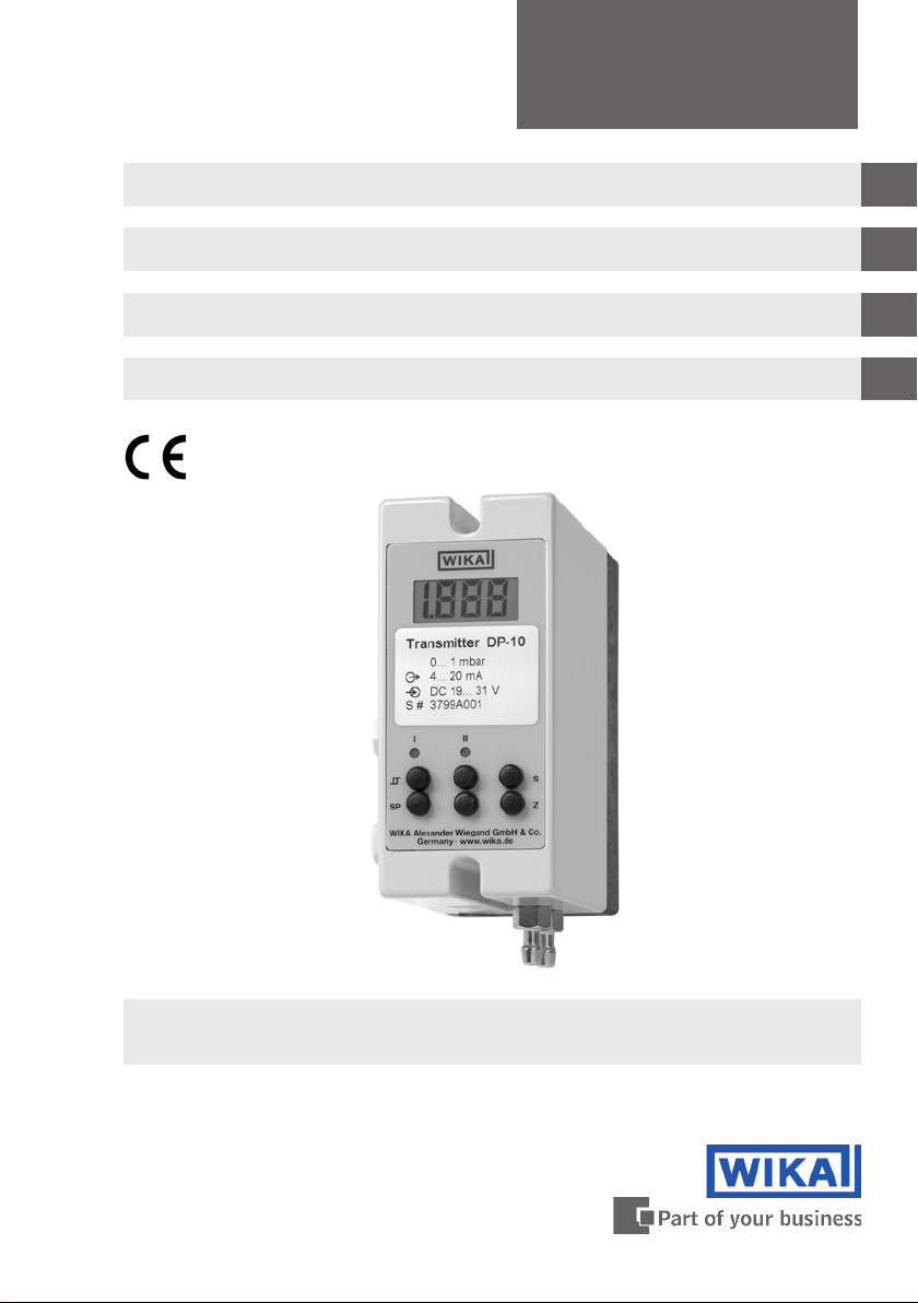
Differential Pressure Transmitter, Model DP-10
Differenzdruck-Messumformer, Typ DP-10
Transmetteur de pression différentielle, Type DP-10
Transmisor de presión diferencial, Modelo DP-10
GB
D
F
E
Differential Pressure Transmitter, Model DP-10
Page 2
Operating Instructions Model DP-10 Page 3 - 11
GB
Betriebsanleitung Typ DP-10 Seite 12 - 21
D
F
Mode d'emploi Type DP-10 Page 22 - 31
E
Manual de Instrucciones Modelo DP-10 Página 32 - 41
Information
This symbol provides you with information, notes and tips.
Warning!
This Symbol warns you against actions that can cause injury to
people or damage to the instrument.
2333401 07/2009 GB/D/F/E
2
Page 3

Contents
Contents
1. Safety instructions 4
Measuring principle 4
2.
3. Mounting 5
3.1
Mounting instructions
3.2
Process connections
4. Dimensions in mm 6
5. Electrical connection 6
6. Calibration instructions 8
6.1
Zero point adjustment (Z)
6.2
Span adjustment (S)
6.3
Adjustment of the alarm contacts
7. Specifications 10
GB
5
5
8
8
8
8. EC-Declaration of Conformity 42
2333401 07/2009 GB/D/F/E
WIKA Operating Instructions Differential Pressure Transmitter 3
Page 4
1. Safety instructions / 2. Measuring principle
1. Safety instructions
GB
Please observe the following operating parameters
The relevant national safety provisions (e.g. VDE 0100) must be
observed when mounting, putting into commission and operating this pressure transmitter. Severe injuries and/or damage
might occur as a result of non-compliance with the corresponding provisions. Only qualified personnel is authorised to work on
these instruments.
The pressure transmitter is exclusively suitable for dry, clean,
non-aggressive gases.
Do not blow into the process connections!
The measuring cell might be damaged by the respiratory
pressure.
Max. medium/ambient temperature: 10 ... 50 °C
It has to be made sure that during transportation both
process connections are open. Instruments with absolute
pressure measuring ranges must be transported in pressure
compensation cabins.
2. Measuring principle
The pressure mesurement is realised via a sensitive diaphragm or, in the case of
absolute pressure measuring ranges, a capsule which is adapted to the measuring
range. An inductive system generates a linear signal which changes in proportion to
the prevailing pressure.
4
WIKA Operating Instructions Differential Pressure Transmitter
2333401 07/2009 GB/D/F/E
Page 5
3. Mounting
3. Mounting
The differential pressure transmitter is designed for wall-mounting. After unscrewing
the two screws at the case the black connection socket can be pulled off the case.
The socket has rated break points for the fastening screws.
3.1 Mounting instructions
The wall-mounting should be carried out in a vertical position, i.e. the process
connections facing down, because the instrument was adjusted in this position.
Thus a possible condensate penetration into the pressure line is avoided.
The mounting location should be free of shocks, vibrations and heat irradiation.
The instrument should not be mounted in the close environment of sources of
interference (e.g. transformers, motors, senders).
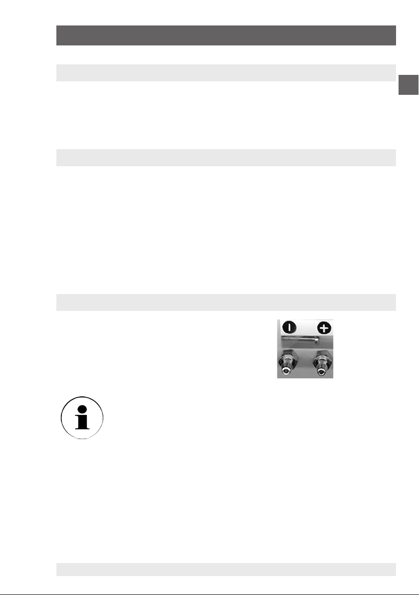
3.2 Process connections
GB
2 x hose connection 6.6 x 11 mm
for hoses with an inside diameter of 5 ... 6 mm.
Pressure is to be connected to the „+“ connection.
Vacuum is to be connected to the „-“ connection.
Instruments with absolute pressure measuring ranges have only
one process connection.
2333401 07/2009 GB/D/F/E
WIKA Operating Instructions Differential Pressure Transmitter 5
Page 6
4. Dimensions in mm / 5. Electrical connection
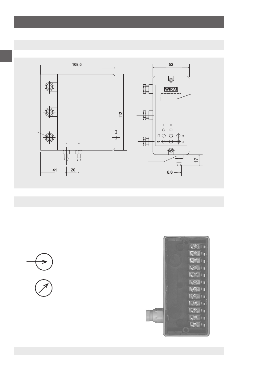
4. Dimensions in mm
GB
M12 x 1.5
Digital display
SW 10
5. Electrical connection
The cable is led through the M12 x 1.5 gland into the connection socket. In the
socket are screw terminals for the wiring (terminal area up to 1.5 mm²).
Power supply
Sink e.g. display
6
WIKA Operating Instructions Differential Pressure Transmitter
2333401 07/2009 GB/D/F/E
Page 7
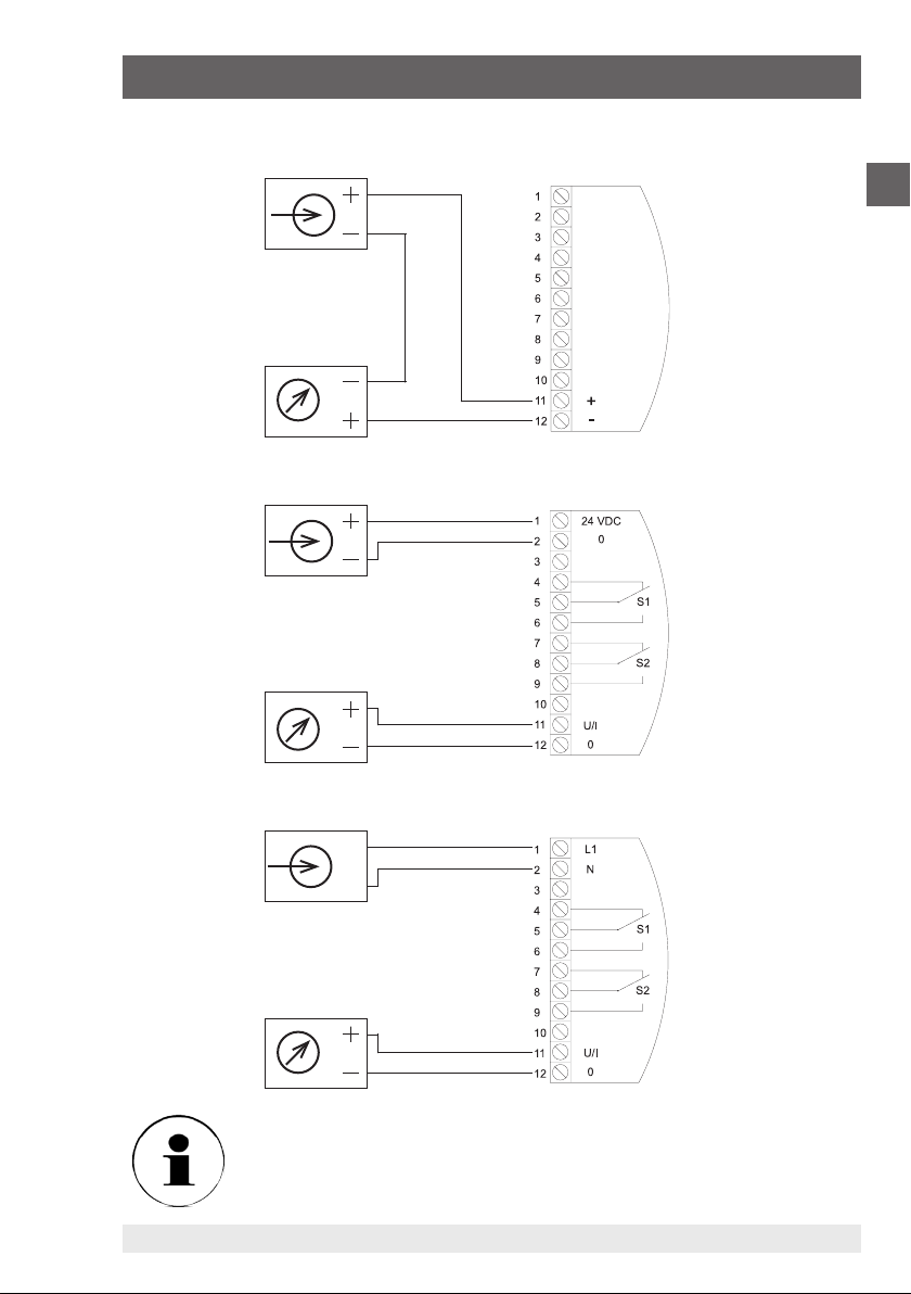
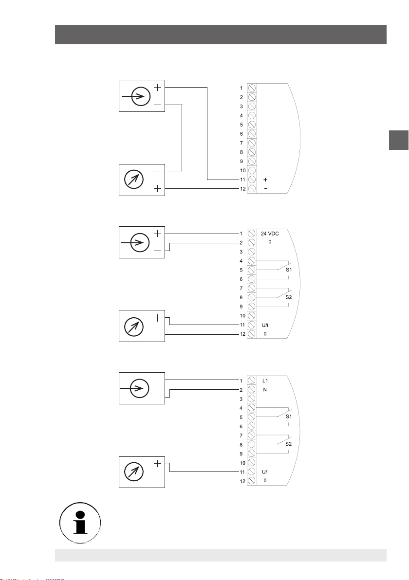
5. Electrical connection
2-wire
3-wire
GB
4-wire (AC-Supply)
L1
N
Be cautious when connecting supply voltages.
Do not connect supply voltage to the output terminals
2333401 07/2009 GB/D/F/E
WIKA Operating Instructions Differential Pressure Transmitter 7
Page 8

6. Calibration instructions
6. Calibration instructions
GB
Please start the calibration only after a running-in period of approx.
30 - 60 minutes.
6.1 Zero point adjustment (Z)
For the zero point adjustment both process connections must be open. After pulling
off the rubber plugs at the instrument‘s front the output signal can be adjusted with
the zero potentiometer (Z).
For the adjustment of pressure transmitters with absolute pressure measuring range
the process connection is to be connected to a pressure generator and an absolute
pressure reference via a T-piece. Subsequently an absolute pressure is generated for
which the output signal shall be: 0 V / 0 mA or 4 mA. Now the output signal can be
adjusted with the zero potentiometer (Z).
6.2 Span adjustment (S)
For the span adjustment the nominal pressure must be connected via a T-piece from
the pressure generation to the pressure reference and the pressure channel.
The WIKA precision calibrator model CPC2000, which has a pressure generation
and a pressure reference, is excellently suitable for this task.
Pressure is to be connected to the “+” connection and vacuum to the “-” connection. Now the output signal may be adjusted with the span potentiometer (S).
6.3 Adjustment of the alarm contacts
For the adjustment of the alarm contacts the reference pressure must be applied
at which the contact is supposed to close. This is accomplished with a pressure
generator which is connected to the pressure reference and the pressure channel via
a T-piece. Pressure is to be connected to the “+” connection and vacuum to the “-”
connection. The potentiometer of the switch point SP I or II must be adjusted until
the red LED above the respective potentiometer lights up, i.e. the switch value has
been reached and the contact closes.
8
WIKA Operating Instructions Differential Pressure Transmitter
2333401 07/2009 GB/D/F/E
Page 9
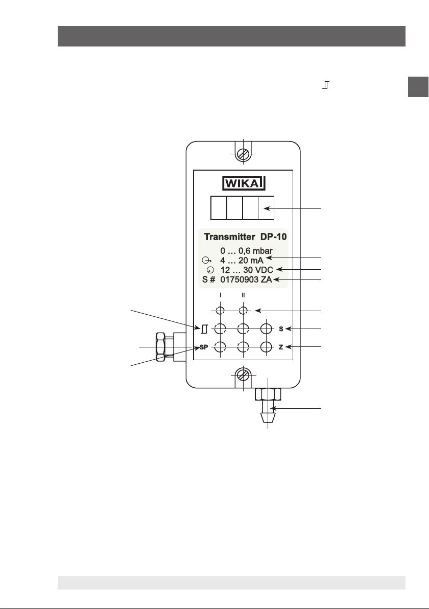
6. Calibration instructions
Then the pressure at which the contact is desired to break again must be applied.
Now the respective hysteresis potentiometer must be adjusted ( ) until the LED
goes out again. The switching hysteresis is adjustable within a range of 0 ... 15 %.
3. LCD (optional)
CE
4. Signal
5. Power Supply
6. Product No.
GB
1. Potentiometer for
switching hysteresis
2. Potentiometer for
switching points
2333401 07/2009 GB/D/F/E
7. Alarm contacts
(optional)
8. Span potentiometer
9. Zero potentiometer
10. Process connection
WIKA Operating Instructions Differential Pressure Transmitter 9
Page 10
7. Specifications
7. Specifications
GB
Specifications Model DP-10
Pressure ranges
Over pressure safety mbar 3 5 8 12.5 20 30 50 80 125
Pressure ranges
Over pressure safety mbar 200 300 500 800 1000 1000 1200 2000
Maximum static pressure mbar 1000 {2000}
Pressure reference
Pressure connection mm two hose connections Ø 6.6 x 11 for hoses with
Materials
Wetted parts Ms, CuBe, PU, Ni
Case bottom part: ABS, glass fibre reinforced, top part: ABS
Power supply U
Signal output and Maximum load R
Power consumption mA
Response time (10 ... 90 %) ms approx. 20 {attenuation on request}
Adjustability zero point / span ± 5 % of span
Accuracy ≤ 1.0 % of span (limit point calibration) {0.5 or 0.2 for pressure
Hysteresis ≤ 0.1 % d. Spanne
Repeatability ≤ 0.05 % of span
1-year stability ≤ 0.5 % of span (at reference conditions)
Permissible temperature of
Medium -10 ... +50 °C 14 ... 122 °F
Ambient -10 ... +50 °C {-10 ... +60 °C} 14 ... 122 °F (14 ... 140 °F)
Storage -10 ... +70 °C 14 ... 158 °F
Compensated temperature range +10 ... +50 °C 14 ... 122 °F
Temperature coefficients in compensated temp range:
Mean TC of zero ≤ 0.3 % of span/10K
Mean TC of range ≤ 0.3 % of span/10K
{ } Items in curved brackets are optional extras for additional price.
1) The measuring ranges 0 ... 0.1 mbar; 0 ... 0.25 mbar; 0 ... 0.4 mbar are available on request.
For these measuring ranges a larger measuring cell and consequently also a case with larger dimensions is required.
2) Only with 4 ... 20 mA 2-wire, other output signals on request.
1)
1)
mbar 0.6 1 1.6 2.5 4 6 10 16 25
mbar 40 60 100 160 250 400 600 1000
relative pressure, differential pressure, {absolute pressure2) from
500 mbar abs; special pressure range 800 ... 1200 mbar abs}
inside Ø 5 ... 6 {2 x clamping ring connection G ⅛, Ms}
DC V
B
19 ... 31 {12 ... 30 with signal output 4 ... 20 mA, 2-wire system}
AC V {24, 115 or 230 (respectively ± 10 %, 50 ... 60 Hz)}
A
0 ... 10 V, 3-wire system RA > 2,0 kOhm
{0 ... 5 V, 3-wire system} R
{0 (4)... 20 mA, 3-wire system} R
{4 ... 20 mA, 2-wire system} R
{other on request}
≤ 2,0 kOhm
A
≤ 500 Ohm
A
≤ (U
[V] – 12 V) / 0,02 mA
A
B
≤ 10; (3-/4-wire); (AC-/DC-supply)
range from 2.5 mbar}
2333401 07/2009 GB/D/F/E
10
WIKA Operating Instructions Differential Pressure Transmitter
Page 11
7. Specifications
Specifications Model DP-10
Shock resistance g 10
Suitable media clean, non-aggressive, dry gases
Sensor volume ml approx. 5 (approx. 7 for measuring ranges < 2.5 mbar)
Increase in volume ml approx. 1 at nominal pressure
CE-conformity Interference emission and immunity see EN 61 326 / A1;
{integrated indicator}
Digital LC display, 3 ½-digits; height of digits 10 mm, pick-up rate
Analogue analogue indicator 0 ... 100 %
{Alarm contacts} only with 3-wire systems
Number 1 or 2
Switching function standard setting 2 x max.
Adjustability 1 ... 100 % of span
Switching accuracy ≤ 1 % of span
Switching repeatability 0,2 % of span, typical
Switching hysteresis 0 ... 10 % of span, adjustable
Contacts 1 potential-free relay change-over contact per alarm contact
Contact rating AC 6 A, 230 V with ohmic load
{Root-evolved output signal}
Accuracy 1,0 % of span
Calculation the root is evolved according to the following equations:
Electrical connection via cable gland PG 7 and internal screw terminals in the
Ingress of protection IP54, per EN 60 529 / IEC 529
Weight kg approx. 0.6 {approx. 0.7 with power supply}
Dimensions mm see drawings
Mounting case for wall mounting
{ } Items in curved brackets are optional extras for additional price.
1) The measuring ranges 0 ... 0.1 mbar; 0 ... 0.25 mbar; 0 ... 0.4 mbar are available on request.
For these measuring ranges a larger measuring cell and consequently also a case with larger dimensions is required.
2) Only with 4 ... 20 mA 2-wire, other output signals on request.
declaration of conformity on request european guideline for
low voltages EN 610 10
3/sec.
UR = √ 10 x UL) UL = linear output 0 ... 10 V
IR = √ 20 x IL) IL = linear output 0 ... 20 mA
bottom part of the case, terminal champing diameter 1.5 mm²
GB
2333401 07/2009 GB/D/F/E
WIKA Operating Instructions Differential Pressure Transmitter 11
Page 12

D
Information
Dieses Zeichen gibt Ihnen Informationen, Hinweise oder Tipps.
Warnung!
Dieses Symbol warnt Sie vor Handlungen, die Schäden an
Personen oder am Gerät verursachen können.
WIKA Betriebsanleitung Differenzdruckmessumformer12
2333401 07/2009 GB/D/F/E
Page 13
Inhalt
Inhalt
1. Sicherheitshinweise 14
Messprinzip 14
2.
3. Montage 15
D
3.1
Montagehinweise
3.2
Prozessanschlüsse
4. Abmessungen in mm 16
5. Elektrischer Anschluss 16
6. Kalibrieranleitung 18
6.1
Einstellung des Nullpunktes (Z)
6.2
Einstellung der Spanne (S)
6.3
Einstellung der Grenzkontakte
7. Technische Daten 20
8. EG-Konformitätserklärung 42
15
15
18
18
18
2333401 07/2009 GB/D/F/E
WIKA Betriebsanleitung Differenzdruckmessumformer 13
Page 14
1. Sicherheitshinweise / 2. Messprinzip
1. Sicherheitshinweise
Beachten Sie unbedingt bei Montage, Inbetriebnahme und
D
Bitte beachten Sie folgende Betriebsparameter
Betrieb dieses Druckmessumformers die entsprechenden nationalen Sicherheitsvorschriften
(z. B.: VDE 0100). Bei Nichtbeachten entsprechender
Vorschriften können schwere Körperverletzungen und/oder
Sachschäden auftreten.
Nur entsprechend qualifiziertes Personal darf an diesen Geräten
arbeiten.
Der Druckmessumformer ist ausschließlich für trockene,
saubere, nicht aggressive Gase geeignet.
Nicht in die Prozessanschlüsse blasen!
Die Messzelle kann durch den Lungendruck beschädigt
werden.
Max. Messstoff-/Umgebungstemperatur: 10 ... 50 °C
Beim Transport ist darauf zu achten, dass beide Prozessan-
schlüsse offen sind. Geräte mit Absolutdruck-Messbereichen
müssen bei Luftfracht in Kabinen mit Druckausgleich befördert werden.
2. Messprinzip
Die Druckmessung erfolgt über eine dem Messbereich angepasste, empfindliche
Plattenfeder, bzw. einer Kapselfeder bei Absolutdruck-Messbereichen. Ein induktives System erzeugt ein lineares Signal, das sich proportional zum anstehenden
Druck verändert.
WIKA Betriebsanleitung Differenzdruckmessumformer14
2333401 07/2009 GB/D/F/E
Page 15

3. Montage
3. Montage
Der Differenzdruck-Messumformer ist für Wandmontage vorgesehen. Nach dem
Lösen der beiden Schrauben am Gehäuse kann der schwarze Anschluss-Sockel
vom Gehäuse abgezogen werden. Im Sockel sind Sollbruchstellen für die Befestigungsschrauben vorhanden.
3.1 Montagehinweise
Der Wandanbau sollte in vertikaler Lage erfolgen, d. H. die Prozessanschlüsse
zeigen nach unten, da das Gerät in dieser Lage eingestellt wurde. Das eventuelle
Eindringen von Kondensat in die Druckleitungen wird so vermieden.
Der Montageort sollte frei von Erschütterungen, Vibrationen, sowie von Wärme-
einstrahlung sein.
Die Montage sollte nicht in unmittelbarer Nähe von Störquellen (z. B. Trafos,
Motoren, Sender) erfolgen.
3.2 Prozessanschlüsse
D
2 x Schlauchanschluss 6,6 x 11 mm
für Schläuche mit Innendurchmesser 5 ... 6 mm.
Ein positiver Überdruck wird an den „+” Eingang angeschlossen.
Ein negativer Überdruck wird an den „-“ Eingang angeschlossen.
Geräte mit Absolutdruck-Messbereichen verfügen nur über einen
Prozessanschluss.
2333401 07/2009 GB/D/F/E
WIKA Betriebsanleitung Differenzdruckmessumformer 15
Page 16

4. Abmessungen in mm / 5. Elektrischer Anschluss
4. Abmessungen in mm
D
M12 x 1,5
SW 10
Anzeigefeld
Digitalanzeige
5. Elektrischer Anschluss
Das Kabel wird durch die M12 x 1,5 Verschraubung in den Anschlusssockel geführt.
Im Sockel befinden sich Schraubklemmen für die Verdrahtung (Klemmbereich bis
1,5 mm²).
Hilfsenergie
Verbraucher
z. B. Anzeige
WIKA Betriebsanleitung Differenzdruckmessumformer16
2333401 07/2009 GB/D/F/E
Page 17

5. Elektrischer Anschluss
2-Leiter
3-Leiter
D
4-Leiter (AC-Versorgung)
L1
N
Vorsicht beim Anschließen von Versorgungsspannungen.
Versorgungsspannung nicht an die Ausgangsklemmen anschlie-
2333401 07/2009 GB/D/F/E
ßen.
WIKA Betriebsanleitung Differenzdruckmessumformer 17
Page 18

6. Kalibrieranleitung
6. Kalibrieranleitung
Bitte beginnen Sie mit der Kalibrierung erst nach einer Einlaufzeit
D
6.1 Einstellung des Nullpunktes (Z)
Zum Abgleich des Nullpunktes müssen beide Druckeingänge offen sein. Nach dem
Abziehen der Gummistopfen auf der Gerätevorderseite kann das Ausgangssignal mit
dem Nullpunktpotentiometer (Z) eingestellt werden.
Beim Abgleich von Druckmessumformern mit Absolutdruck-Messbereich wird der
Druckeingang über ein T-Stück mit einer Druckerzeugung und mit einer Absolutdruckreferenz verbunden. Danach wird der Absolutdruck erzeugt, bei dem das
Ausgangssignal: 0 V bzw. 0 mA oder 4 mA betragen soll. Jetzt kann das Ausgangssignal mit dem Nullpunktpotentiometer (Z) eingestellt werden.
6.2 Einstellung der Spanne (S)
von ca. 30 ... 60 Minuten.
Zum Abgleich der Spanne wird der Nenndruck über ein T-Stück von der Druckerzeugung an die Druckreferenz und den Druckkanal angeschlossen.
Der WIKA Präzisionskalibrator Typ CPC2000, der über eine Druckerzeugung, sowie
über die Druckreferenz verfügt, ist hierfür hervorragend geeignet.
Positiver Überdruck wird an den „+“ Eingang und negativer Überdruck an den „–“
Eingang angeschlossen. Nun kann das Ausgangssignal mit dem Spanne-Potentiometer (S) eingestellt werden.
6.3 Einstellung der Grenzkontakte
Zur Einstellung der Grenzkontakte wird der Druck angelegt, bei dem der Kontakt
schließen soll. Dies erfolgt mit einer Druckerzeugung, die über ein T-Stück mit der
Druckreferenz und dem Druckkanal verbunden ist. Positiver Überdruck wird an
den „+“ Eingang und negativer Überdruck an den „–“ Eingang angeschlossen. Das
Potentiometer des Schaltpunktes SP I bzw. II wird solange verstellt, bis die rote LED
oberhalb des jeweiligen Potentiometers aufleuchtet. Damit ist der Einschaltwert
erreicht, das Relais ist geschlossen.
WIKA Betriebsanleitung Differenzdruckmessumformer18
2333401 07/2009 GB/D/F/E
Page 19

6. Kalibrieranleitung
Danach wird der Druck angelegt, bei dem sich der Kontakt wieder öffnen soll. Jetzt
wird das entsprechende Hysterese- Potentiomer ( ) solange verstellt, bis die LED
wieder erlischt. Die Schalthysterese ist im Bereich von 0 ... 15 % einstellbar.
3. LCD-Anzeige (Option)
CE
4. Signal
5. Hilfsenergie
6. Fabrik-Nr.
7.
1. Potentiometer für
Schalthysterese
Grenzkontakte (Option)
8. Spanne-Potentiometer
D
9. Nullpunkt-Potentio-
2. Potentiometer für
Schaltpunkte
2333401 07/2009 GB/D/F/E
meter
10. Prozessanschluss
WIKA Betriebsanleitung Differenzdruckmessumformer 19
Page 20

7. Technische Daten
7. Technische Daten
Technische Daten Typ DP-10
D
Messbereich
Überlastgrenze mbar 3 5 8 12,5 20 30 50 80 125
Messbereich
Überlastgrenze mbar 200 300 500 800 1000 1000 1200 2000
Maximaler statischer Druck mbar 1000 {2000}
Druckart Relativdruck, Differenzdruck {Absolutdruck2) ab 500 mbar
Druckanschluss mm zwei Schlauchanschlüsse Ø 6,6 x 11 für Schläuche mit Innen-
Werkstoff
Hilfsenergie U
Ausgangssignal und zulässige max.
Bürde R
Stromaufnahme mA ≤ 10; (3-/4-Leiter); (AC-/DC-Versorgung)
Einstellzeit (10 ... 90 %) ms ca. 20 {Dämpfung auf Anfrage}
Einstellbarkeit: Nullpunkt/Spanne ± 5 % d. Spanne
Kennlinienabweichung √ 1,0 % d. Spanne (Grenzpunkteinstellung) {0,5 oder 0,2 ab
Hysterese ≤ 0,1 % d. Spanne
Reproduzierbarkeit ≤ 0,05 % d. Spanne
Stabilität pro Jahr ≤ 0,5 % d. Spanne (bei Referenzbedingungen)
Zulässige Temperaturen
Kompensierter Temperaturbereich +10 ... +50 °C 14 ... 122 °F
Temperaturkoeffizienten im Kompensierten Temperaturbereich:
{ } Angaben in geschweiften Klammern beschreiben gegen Mehrpreis lieferbare Sonderheiten
1) Die Messbereiche 0 ... 0,1 mbar; 0 ... 0,25 mbar; 0 ... 0,4 mbar sind auf Anfrage lieferbar.
Bei diesen Messbereichen wird eine größere Messzelle und deshalb ein Gehäuse mit größeren Abmessungen benötigt.
2) Nur bei 4 ... 20 mA Zweileiter, andere Ausgangssignale auf Anfrage.
1)
1)
mbar 0,6 1 1,6 2,5 4 6 10 16 25
mbar 40 60 100 160 250 400 600 1000
abs; Sondermessbereich 800 ... 1200 mbar abs}
Ø 5 ... 6 {2 x Klemmringverschraubung G ⅛, Ms}
Messstoffberührte Teile Ms, CuBe, PU, Ni
Gehäuse Unterteil: ABS, glasfaserverstärkt, Oberteil: ABS
B
DC V 19 ... 31 {12 ... 30 bei Ausgang 4 ... 20 mA, Zweileiter}
AC V {24, 115 oder 230 (jeweils ± 10 %, 50 ... 60 Hz)}
0 ... 10 V, Dreileiter RA > 2,0 kOhm
A
{0 ... 5 V, Dreileiter} R
{0 (4)... 20 mA, Dreileiter} R
{4 ... 20 mA, Zweileiter} R
{andere auf Anfrage}
≤ 2,0 kOhm
A
≤ 500 Ohm
A
≤ (U
[V] – 12 V) / 0,02 mA
A
B
Messbereich 2,5 mbar}
Messstoff -10 ... +50 °C 14 ... 122 °F
Umgebung -10 ... +50 °C {-10 ... +60 °C} 14 ... 122 °F (14 ... 140 °F)
Lagerung -10 ... +70 °C 14 ... 158 °F
Mittlerer TK des Nullpunktes ≤ 0,3 % d. Spanne/10K
Mittlerer TK der Spanne ≤ 0,3 % d. Spanne/10K
2333401 07/2009 GB/D/F/E
WIKA Betriebsanleitung Differenzdruckmessumformer20
Page 21

7. Technische Daten
Technische Daten Typ DP-10
Schockbelastbarkeit g 10
Geeignete Messstoffe saubere, nicht aggressive, trockene Gase
Sensorvolumen ml ca. 5 (ca. 7 bei Messbereichen < 2,5 mbar)
Volumenzuwachs ml ca. 1 bei Nenndruck
CE-Kennzeichen Störemission und Störfestigkeit nach EN 61 326/A1,
{integrierte Anzeige}
Digital LCD-Anzeige, 3 ½-stellig; Ziffernhöhe 10 mm, Wandlungsrate
Analog Analoganzeige 0 ... 100 %
{Grenzkontakte} nur bei Dreileitersystemen
Anzahl 1 oder 2
Schaltfunktion Standardeinstellung 2 x max.
Einstellbarkeit 1 ... 100 % d. Spanne
Schaltgenauigkeit ≤ 1 % d. Spanne
Schaltreproduzierbarkeit 0,2 % d. Spanne , typisch
Schalthysterese 0 ... 10 % d. Spanne, einstellbar
Kontakte je 1 potentialfreier Relaisumschaltkontakt pro Grenzkontakt
Kontaktbelastung AC 6 A, 230 V bei ohmscher Last
{radiziertes Ausgangssignal}
Genauigkeit 1,0 % d. Spanne
Berechnung Die Radizierung wird nach folgenden Gleichungen vorgenommen:
Elektrischer Anschluss über Kabelverschraubung PG 7 und innenliegende Schraub-
Schutzart IP54, nach EN 60 529 / IEC 529
Masse kg ca. 0,6 {ca. 0,7 mit Netzteil}
Maße mm siehe Abmessungen
Montage Gehäuse für Wandmontage
{ } Angaben in geschweiften Klammern beschreiben gegen Mehrpreis lieferbare Sonderheiten
1) Die Messbereiche 0 ... 0,1 mbar; 0 ... 0,25 mbar; 0 ... 0,4 mbar sind auf Anfrage lieferbar.
Bei diesen Messbereichen wird eine größere Messzelle und deshalb ein Gehäuse mit größeren Abmessungen benötigt.
2) Nur bei 4 ... 20 mA Zweileiter, andere Ausgangssignale auf Anfrage.
Konformitätserklärung auf Anfrage,
Niederspannungsrichtlinie EN 610 10
3/sek.
UR = √ 10 x UL) UL = linearer Ausgang 0 ... 10 V
IR = √ 20 x IL) IL = linearer Ausgang 0 ... 20 mA
klemmen im Gehäuseunterteil
Klemmbereich 1,5 mm²
D
2333401 07/2009 GB/D/F/E
WIKA Betriebsanleitung Differenzdruckmessumformer 21
Page 22

F
Information
Ce signe indique des informations, des remarques ou des
conseils.
Avertissement !
Ce symbole vous avertit d‘actions qui sont susceptibles
d‘entraîner des dommages physiques ou matériels.
WIKA Mode d'emploi Transmetteur de pression différentielle22
2333401 07/2009 GB/D/F/E
Page 23

Sommaire
Sommaire
1. Remarques de sécurité 24
Principe de mesure 24
2.
3. Montage 25
3.1
Remarques pour le montage
3.2
Raccords de pression
4. Dimensions en mm 26
5. Raccords électriques 26
6. Instructions de calibration 28
6.1
Réglage du zéro (Z)
6.2
Réglage du gain (S)
6.3
Réglage des seuils d’alarme
7. Caractéristiques techniques 30
8. Déclaration de Conformité CE 43
25
25
28
28
28
F
2333401 07/2009 GB/D/F/E
WIKA Mode d'emploi Transmetteur de pression différentielle 23
Page 24

1. Remarques de sécurité / 2. Principe de mesure
1. Remarques de sécurité
Observez strictement lors du montage, de la mise en service
et de l‘utilisation de ce transmetteur de pression, les prescriptions de sécurité nationales (par exemple VDE 0100). La nonobservance des prescriptions peut provoquer de graves lésions
F
Veuillez respecter les conditions suivantes:
corporelles et/ ou des dégâts matériels. Seul du personnel
qualifié doit travailler sur ces appareils.
Le transmetteur de pression est uniquement adapté pour la
mesure de gaz secs, propres et non aggressifs.
Ne pas souffler dans les raccords pression!
La cellule de mesure peut être détériorée par la pression
pulmonaire.
Température de fluide / ambiante: 10 ... 50 °C
Lors du transport s‘assurer que les deux raccords de
pression sont ouverts. Quant au transport aérien, les
appareils avec plages de mesure en pression absolue doivent
être transportés dans des cabines à compensation de
pression.
2. Principe de mesure
La mesure de pression se fait par une membrane sensible, adaptée à la plage de
mesure, ou par capsule pour les plages de mesure absolues. Un système inductif
génère un signal linéaire changeant proportionnellement par rapport à la pression
appliquée.
WIKA Mode d'emploi Transmetteur de pression différentielle24
2333401 07/2009 GB/D/F/E
Page 25

3. Montage
3. Montage
Le transmetteur de pression différentielle est prévu pour un montage sur paroi.
Après avoir dévissé les deux vis sur le boîtier, le socle de montage peut être retiré du
boîtier. Dans le socle se trouvent des orifices prédécoupés pour le passage des vis
de fixation.
3.1 Remarques pour le montage
Le montage sur paroi doit se faire verticalement, c‘est à dire raccords de pression
dirigés vers le bas, étant donné que l‘appareil a été réglé dans cette position. La
pénétration de condensat dans les conducteurs de pression est ainsi évitée.
Le lieu de montage doit être exempt de chocs, de secousses, de vibrations ainsi
que de radiations thermiques.
Le transmetteur ne doit pas être installé à proximité d’une source d’interférences
magnétiques (Transformateurs, moteurs, )
F
3.2 Raccords de pression
2 raccords pour tuyaux flexibles Ø 6,6 x 11 mm
pour tuyaux d‘un diamètre interne de 5 ... 6 mm.
Une pression positive est raccordée à l‘entrée marquée „+“.
Une pression négative est raccordée à l‘entrée marquée „-“.
Les instruments avec étendues de mesure à pression absolue ne
possèdent qu‘un raccord process.
2333401 07/2009 GB/D/F/E
WIKA Mode d'emploi Transmetteur de pression différentielle 25
Page 26

4. Dimensions en mm / 5. Raccords électriques
4. Dimensions en mm
F
M12 x 1,5
SW 10
fenêtre pour
indicateur
digital
5. Raccords électriques
Le câble est introduit dans le socle de branchement à travers du presse-étoupe M12 x 1,5.
Dans le socle se trouvent des bornes pour le cablâge (section jusqu‘à 1,5 mm²).
Alimentation
WIKA Mode d'emploi Transmetteur de pression différentielle26
Indicateur
2333401 07/2009 GB/D/F/E
Page 27
5. Raccords électriques
2 fils
3 fils
F
4 fils (AC - Alimentation de courant alternatif)
L1
N
Attention lors du branchement de la tension d‘alimentation.
Ne pas brancher la tension d‘alimentation sur les bornes de
2333401 07/2009 GB/D/F/E
sortie.
WIKA Mode d'emploi Transmetteur de pression différentielle 27
Page 28

6. Instructions de calibration
6. Instructions de calibration
Veuillez commencer la calibration après un temps de stabilisation de
30 - 60 minutes.
F
6.1 Réglage du zéro (Z)
Pour le réglage du zéro, il est nécessaire que les deux entrées pression soient
ouvertes. Après avoir retiré les bouchons de caoutchouc sur le devant de l‘appareil,
le signal de sortie peut être réglé à l‘aide du potentiomètre de zéro (Z).
Lors du réglage du transmetteur de pression avec une plage de mesure de pression
absolue, l‘entrée de pression est reliée par un raccord en T à un générateur de
pression et à une référence de pression absolue. Par la suite la pression absolue est
appliquée pour laquelle le signal de sortie doit être de:
0 V, 0 mA ou 4 mA. Maintenant le signal de sortie peut être réglé à l‘aide du potentiomètre (Z).
6.2 Réglage du gain (S)
Pour le réglage du gain, la pression nominale est appliquée, par l‘intermédiaire d‘un
raccord en T, à une référence de pression et au canal de pression. Le calibrateur
de précision WIKA type CPC2000 qui est équipé d‘un générateur ainsi que d‘une
référence de pression est particulièrement approprié pour cette opération.
La pression positive est raccordée à l‘entrée ”+“ et la pression négative à l‘entrée
”-“. Maintenant le signal de sortie peut être réglé par le potentiomètre de gain (S).
6.3 Réglage des seuils d’alarme
Pour le réglage des seuils d’alarme, on applique la pression sous laquelle le contact
doit être fermé. Ceci se fait à l’aide d’un générateur de pression relié par un raccord
en T à une référence de pression et au canal de pression. La pression positive est
raccordée à l’entrée ”+“ et la pression négative à l’entrée ”-“. Le potentiomètre du
seuil d’alarme SP I ou SP II est déplacé jusqu’à ce que la DEL rouge se trouvant audessus du potentiomètre respectif s’allume. La valeur de commutation est atteinte,
le relais est fermé.
WIKA Mode d'emploi Transmetteur de pression différentielle28
2333401 07/2009 GB/D/F/E
Page 29

6. Instructions de calibration
Ensuite on applique la pression à laquelle le contact doit s’ouvrir à nouveau. Maintenant on déplace le potentiomètre d’hystéréris correspondant ( ) jusqu’à ce que la
DEL s’éteigne. La plage d’hystérésis est réglable dans une zone de 0 ... 15 %.
3. LCD (option)
CE
4. Signal de sortie
5. Alimentation
6. No. Serie
F
1. Potentiomètre de
reg-lage pour l‘hystérésis
2. Potentiomètre des
points de communtation
2333401 07/2009 GB/D/F/E
7. Contacts de limite
8. Marge-potentiomètre
9. Zéro-potentiomètre
10. Raccordement
process
WIKA Mode d'emploi Transmetteur de pression différentielle 29
Page 30

7. Caractéristiques techniques
7. Caractéristiques techniques
Specifications Model DP-10
Pressure ranges
Over pressure safety mbar 3 5 8 12.5 20 30 50 80 125
F
Pressure ranges
Over pressure safety mbar 200 300 500 800 1000 1000 1200 2000
Maximum static pressure mbar 1000 {2000}
Pressure reference
Pressure connection mm two hose connections Ø 6.6 x 11 for hoses with
Materials
Wetted parts Ms, CuBe, PU, Ni
Case bottom part: ABS, glass fibre reinforced, top part: ABS
Power supply U
Signal output and Maximum load R
Power consumption mA
Response time (10 ... 90 %) ms approx. 20 {attenuation on request}
Adjustability zero point / span ± 5 % of span
Accuracy ≤ 1.0 % of span (limit point calibration) {0.5 or 0.2 for pressure
Hysteresis ≤ 0.1 % d. Spanne
Repeatability ≤ 0.05 % of span
1-year stability ≤ 0.5 % of span (at reference conditions)
Permissible temperature of
Medium -10 ... +50 °C 14 ... 122 °F
Ambient -10 ... +50 °C {-10 ... +60 °C} 14 ... 122 °F (14 ... 140 °F)
Storage -10 ... +70 °C 14 ... 158 °F
Compensated temperature range +10 ... +50 °C 14 ... 122 °F
Temperature coefficients in compensated temp range:
Mean TC of zero ≤ 0.3 % of span/10K
Mean TC of range ≤ 0.3 % of span/10K
{ } Items in curved brackets are optional extras for additional price.
1) The measuring ranges 0 ... 0.1 mbar; 0 ... 0.25 mbar; 0 ... 0.4 mbar are available on request.
For these measuring ranges a larger measuring cell and consequently also a case with larger dimensions is required.
2) Only with 4 ... 20 mA 2-wire, other output signals on request.
1)
1)
mbar 0.6 1 1.6 2.5 4 6 10 16 25
mbar 40 60 100 160 250 400 600 1000
relative pressure, differential pressure, {absolute pressure2) from
500 mbar abs; special pressure range 800 ... 1200 mbar abs}
inside Ø 5 ... 6 {2 x clamping ring connection G ⅛, Ms}
DC V
B
19 ... 31 {12 ... 30 with signal output 4 ... 20 mA, 2-wire system}
AC V {24, 115 or 230 (respectively ± 10 %, 50 ... 60 Hz)}
A
0 ... 10 V, 3-wire system RA > 2,0 kOhm
{0 ... 5 V, 3-wire system} R
{0 (4)... 20 mA, 3-wire system} R
{4 ... 20 mA, 2-wire system} R
{other on request}
≤ 2,0 kOhm
A
≤ 500 Ohm
A
≤ (U
[V] – 12 V) / 0,02 mA
A
B
≤ 10; (3-/4-wire); (AC-/DC-supply)
range from 2.5 mbar}
2333401 07/2009 GB/D/F/E
WIKA Mode d'emploi Transmetteur de pression différentielle30
Page 31
7. Caractéristiques techniques
Specifications Model DP-10
Shock resistance g 10
Suitable media clean, non-aggressive, dry gases
Sensor volume ml approx. 5 (approx. 7 for measuring ranges < 2.5 mbar)
Increase in volume ml approx. 1 at nominal pressure
CE-conformity Interference emission and immunity see EN 61 326 / A1;
{integrated indicator}
Digital LC display, 3 ½-digits; height of digits 10 mm, pick-up rate
Analogue analogue indicator 0 ... 100 %
{Alarm contacts} only with 3-wire systems
Number 1 or 2
Switching function standard setting 2 x max.
Adjustability 1 ... 100 % of span
Switching accuracy ≤ 1 % of span
Switching repeatability 0,2 % of span, typical
Switching hysteresis 0 ... 10 % of span, adjustable
Contacts 1 potential-free relay change-over contact per alarm contact
Contact rating AC 6 A, 230 V with ohmic load
{Root-evolved output signal}
Accuracy 1,0 % of span
Calculation the root is evolved according to the following equations:
Electrical connection via cable gland PG 7 and internal screw terminals in the
Ingress of protection IP54, per EN 60 529 / IEC 529
Weight kg approx. 0.6 {approx. 0.7 with power supply}
Dimensions mm see drawings
Mounting case for wall mounting
{ } Items in curved brackets are optional extras for additional price.
1) The measuring ranges 0 ... 0.1 mbar; 0 ... 0.25 mbar; 0 ... 0.4 mbar are available on request.
For these measuring ranges a larger measuring cell and consequently also a case with larger dimensions is required.
2) Only with 4 ... 20 mA 2-wire, other output signals on request.
declaration of conformity on request european guideline for
low voltages EN 610 10
3/sec.
UR = √ 10 x UL) UL = linear output 0 ... 10 V
IR = √ 20 x IL) IL = linear output 0 ... 20 mA
bottom part of the case, terminal champing diameter 1.5 mm²
F
2333401 07/2009 GB/D/F/E
WIKA Mode d'emploi Transmetteur de pression différentielle 31
Page 32

E
Información
Este signo indica informaciones, indicaciones o consejos.
¡Advertencia!
Este símbolo advierte sobre acciones que pueden provocar
daños personales o al equipo.
WIKA Manual de Instrucciones Transmisor de presión diferencial32
2333401 07/2009 GB/D/F/E
Page 33

Contenido
Contenido
1. Instrucciones de seguridad 34
Principio de medida 34
2.
3. Montaje 35
3.1
Instrucciones para el montaje
3.2
Conexiones de procesamiento
4. Dimensiones en mm 36
5. Conexión eléctrica 36
6. Instrucciones para el calibrado 38
6.1
Ajuste de punto cero (Z)
6.2
Ajuste de span (S)
6.3
Ajuste de los contactos
7. Datos técnicos 40
8. Declaración de Conformidad CE 43
35
35
38
38
38
E
2333401 07/2009 GB/D/F/E
WIKA Manual de Instrucciones Transmisor de presión diferencial 33
Page 34

1. Instrucciones de seguridad / 2. Principio de medida
1. Instrucciones de seguridad
Durante el montaje, la puesta en servicio y el funcionamiento
de este transmisor de presión es obligatorio tener en cuenta
las correspondientes prescripciones nacionales de seguridad
(p. ej.: VDE 0100 (Asociación de Electrotécnicos Alemanes)).
En caso de incumplimiento de las respectivas prescripciones
pueden producirse daños físicos y/o daños materiales conside-
E
Tenga en cuenta los siguientes parámetros de funcionamiento
rables.
Dichos aparatos deben ser utilizados únicamente por personal
cualificado.
El transmisor de presión está concebido exclusivamente
para gases secos, limpios y no agresivos.
No sople en las conexiones de procesamiento.
La célula de medida puede deteriorarse por la presión.
Temperatura ambiente / de la sustancia de medición máxima:
10 ... 50 °C
Durante el transporte es debe prestar atención a que ambas
conexiones de procesamiento estén abiertas. En caso de
transporte aéreo, los aparatos con gamas de medición de
presión absoluta deben ser transportados en cabinas con
compensación de presión.
2. Principio de medida
La medición de presión se realiza con una gama de medición adecuada, con una
membrana elástica y con un muelle de membrana elástica para gamas de medición
de presión absoluta. Un sistema inductivo produce una señal lineal, que se va
modificando proporcionalmente a la presión existente.
34
WIKA Manual de Instrucciones Transmisor de presión diferencial
2333401 07/2009 GB/D/F/E
Page 35

3. Montaje
3. Montaje
El transmisor de presión diferencial está previsto para el montaje en pared. Tras
aflojar los dos tornillos de la carcasa se podrá extraer el casquillo de conexión negro
de la carcasa. En el casquillo hay puntos de rotura controlada para los tornillos de
fijación.
3.1 Instrucciones para el montaje
El montaje en pared debe realizarse en posición vertical, es decir, las conexiones
de procesamiento señalan hacia abajo, debido a que el aparato se ha ajustado en
esta posición. De este modo, se evita la posible penetración de condensado en
las tuberías a presión.
El lugar de montaje debe estar libre de golpes, vibraciones y de radiaciones
térmicas.
El montaje no debe realizarse en las cercanías a fuentes de interferencias (p. ej.
transformadores, motores, emisores).
3.2 Conexiones de procesamiento
2 x racores de empalme de Ø 6,6 x 11 mm para
tubos flexibles de un diámetro interior de 5 ... 6 mm.
En la entrada „+“ se conecta una sobrepresión positiva.
En la entrada „-“ se conecta una sobrepresión negativa.
Los aparatos con gamas de medición de presión absoluta dispo-
nen solo de una conexión de procesamiento.
E
2333401 07/2009 GB/D/F/E
WIKA Manual de Instrucciones Transmisor de presión diferencial 35
Page 36

4. Dimensiones en mm / 5. Conexión eléctrica
4. Dimensiones en mm
E
M12 x 1,5
SW 10
Campo de indicación para
digital
5. Conexión eléctrica
El cable se introduce en el casquillo de conexión a través de la unión roscada M12
x 1,5. En el casquillo se encuentran bornes roscados para el cableado (margen de
sujeción de hasta 1,5 mm²).
Energía auxiliar
Consumidor de
energía, p. ej, indicación
WIKA Manual de Instrucciones Transmisor de presión diferencial36
2333401 07/2009 GB/D/F/E
Page 37

5. Conexión eléctrica
Conductor bifilar
3-hilos
E
4-hilos (AC - Alimentación eléctrica)
L1
N
Proceda con cuidado durante las conexiones de tensiones de
alimentación.
No conecta la tensión de alimentación a los bornes de salida.
2333401 07/2009 GB/D/F/E
WIKA Manual de Instrucciones Transmisor de presión diferencial 37
Page 38

6. Instrucciones para el calibrado
6. Instrucciones para el calibrado
Comience con el calibrado después de un tiempo de rodaje de
aprox. 30 - 60 minutos.
6.1 Ajuste de punto cero (Z)
E
Para el ajuste del punto cero, ambas entradas de presión deberán estar abiertas.
Tras retirar los tapones de goma situados en la parte delantera del aparato, se podrá
ajustar la señal de salida con el potenciómetro de punto cero (Z).
En el ajuste de convertidores de medición de presión con gama de medición de
presión absoluta, la entrada de presión se conecta con la fuente de generación de
presión y con la referencia de presión absoluta mediante una pieza en T. A continuación se genera la presión absoluta y la señal de salida deberá ser de 0 V y 0 mA o 4
mA. Ahora se podrá ajustar la señal de salida con el potenciómetro de punto cero (Z).
6.2 Ajuste de span (S)
Para ajustar el intervalo de medida, la presión nominal se conecta mediante una
pieza en T desde la fuente de generación de presión a la referencia de presión y al
canal de presión.
Para este procedimiento resulta especialmente adecuado el calibrador de precisión
WIKA tipo CPC2000, que dispone una fuente de generación de presión y de una
referencia de presión.
La sobrepresión positiva se conecta en la entrada „+“ y la sobrepresión negativa
en la entrada „-“. Ahora se podrá ajustar la señal de salida con el potenciómetro de
intervalo de medida (S).
6.3 Ajuste de los contactos
Para el ajuste de los contactos se aplica la presión con la que se debe bloquear el
contacto. Esto se realiza con una fuente de generación de presión que se encuentra conectada con la referencia de presión y con el canal de presión mediante una
pieza en T. La sobrepresión positiva se conecta en la entrada „+“ y la sobrepresión
negativa en la entrada „-“.
WIKA Manual de Instrucciones Transmisor de presión diferencial38
2333401 07/2009 GB/D/F/E
Page 39

6. Instrucciones para el calibrado
El potenciómetro del punto de conexión SP I y II se ajusta hasta que se encienda
el LED rojo situado encima del potenciómetro correspondiente. De este modo, se
alcanza el valor de conexión y el relé está cerrado.
Posteriormente, la presión se aplica la presión con la que se deberá desbloquear
nuevamente el contacto. A continuación, se deberá ajustar el potenciómetro de
histéresis ( ) hasta que se vuelva a apagar el LED. La histéresis de conexión se
puede ajustar en un margen de 0 … 15 %.
E
1. Potenciómetro
para la histéresis
de conexión
2. Potenciómetro
para los punots de
conexión
CE
3. Indicación LED (op
cional)
4. Señal
5. Energía auxiliar
6. N° de fábrica
7. Contactos (opcional)
8. Potenciómetro de span
9. Potenciómetro de
punto cero
10. Conexión de proce-
samiento
-
2333401 07/2009 GB/D/F/E
WIKA Manual de Instrucciones Transmisor de presión diferencial 39
Page 40

7. Datos técnicos
7. Datos técnicos
Specifications Model DP-10
Pressure ranges
Over pressure safety mbar 3 5 8 12.5 20 30 50 80 125
Pressure ranges
Over pressure safety mbar 200 300 500 800 1000 1000 1200 2000
Maximum static pressure mbar 1000 {2000}
E
Pressure reference
Pressure connection mm two hose connections Ø 6.6 x 11 for hoses with
Materials
Wetted parts Ms, CuBe, PU, Ni
Case bottom part: ABS, glass fibre reinforced, top part: ABS
Power supply U
Signal output and Maximum load R
Power consumption mA
Response time (10 ... 90 %) ms approx. 20 {attenuation on request}
Adjustability zero point / span ± 5 % of span
Accuracy ≤ 1.0 % of span (limit point calibration) {0.5 or 0.2 for pressure
Hysteresis ≤ 0.1 % d. Spanne
Repeatability ≤ 0.05 % of span
1-year stability ≤ 0.5 % of span (at reference conditions)
Permissible temperature of
Medium -10 ... +50 °C 14 ... 122 °F
Ambient -10 ... +50 °C {-10 ... +60 °C} 14 ... 122 °F (14 ... 140 °F)
Storage -10 ... +70 °C 14 ... 158 °F
Compensated temperature range +10 ... +50 °C 14 ... 122 °F
Temperature coefficients in compensated temp range:
Mean TC of zero ≤ 0.3 % of span/10K
Mean TC of range ≤ 0.3 % of span/10K
{ } Items in curved brackets are optional extras for additional price.
1) The measuring ranges 0 ... 0.1 mbar; 0 ... 0.25 mbar; 0 ... 0.4 mbar are available on request.
For these measuring ranges a larger measuring cell and consequently also a case with larger dimensions is required.
2) Only with 4 ... 20 mA 2-wire, other output signals on request.
1)
1)
mbar 0.6 1 1.6 2.5 4 6 10 16 25
mbar 40 60 100 160 250 400 600 1000
relative pressure, differential pressure, {absolute pressure2) from
500 mbar abs; special pressure range 800 ... 1200 mbar abs}
inside Ø 5 ... 6 {2 x clamping ring connection G ⅛, Ms}
DC V
B
19 ... 31 {12 ... 30 with signal output 4 ... 20 mA, 2-wire system}
AC V {24, 115 or 230 (respectively ± 10 %, 50 ... 60 Hz)}
A
0 ... 10 V, 3-wire system RA > 2,0 kOhm
{0 ... 5 V, 3-wire system} R
{0 (4)... 20 mA, 3-wire system} R
{4 ... 20 mA, 2-wire system} R
{other on request}
≤ 2,0 kOhm
A
≤ 500 Ohm
A
≤ (U
[V] – 12 V) / 0,02 mA
A
B
≤ 10; (3-/4-wire); (AC-/DC-supply)
range from 2.5 mbar}
2333401 07/2009 GB/D/F/E
WIKA Manual de Instrucciones Transmisor de presión diferencial40
Page 41

7. Datos técnicos
Specifications Model DP-10
Shock resistance g 10
Suitable media clean, non-aggressive, dry gases
Sensor volume ml approx. 5 (approx. 7 for measuring ranges < 2.5 mbar)
Increase in volume ml approx. 1 at nominal pressure
CE-conformity Interference emission and immunity see EN 61 326 / A1;
{integrated indicator}
Digital LC display, 3 ½-digits; height of digits 10 mm, pick-up rate
Analogue analogue indicator 0 ... 100 %
{Alarm contacts} only with 3-wire systems
Number 1 or 2
Switching function standard setting 2 x max.
Adjustability 1 ... 100 % of span
Switching accuracy ≤ 1 % of span
Switching repeatability 0,2 % of span, typical
Switching hysteresis 0 ... 10 % of span, adjustable
Contacts 1 potential-free relay change-over contact per alarm contact
Contact rating AC 6 A, 230 V with ohmic load
{Root-evolved output signal}
Accuracy 1,0 % of span
Calculation the root is evolved according to the following equations:
Electrical connection via cable gland PG 7 and internal screw terminals in the
Ingress of protection IP54, per EN 60 529 / IEC 529
Weight kg approx. 0.6 {approx. 0.7 with power supply}
Dimensions mm see drawings
Mounting case for wall mounting
{ } Items in curved brackets are optional extras for additional price.
1) The measuring ranges 0 ... 0.1 mbar; 0 ... 0.25 mbar; 0 ... 0.4 mbar are available on request.
For these measuring ranges a larger measuring cell and consequently also a case with larger dimensions is required.
2) Only with 4 ... 20 mA 2-wire, other output signals on request.
declaration of conformity on request european guideline for
low voltages EN 610 10
3/sec.
UR = √ 10 x UL) UL = linear output 0 ... 10 V
IR = √ 20 x IL) IL = linear output 0 ... 20 mA
bottom part of the case, terminal champing diameter 1.5 mm²
E
2333401 07/2009 GB/D/F/E
WIKA Manual de Instrucciones Transmisor de presión diferencial 41
Page 42
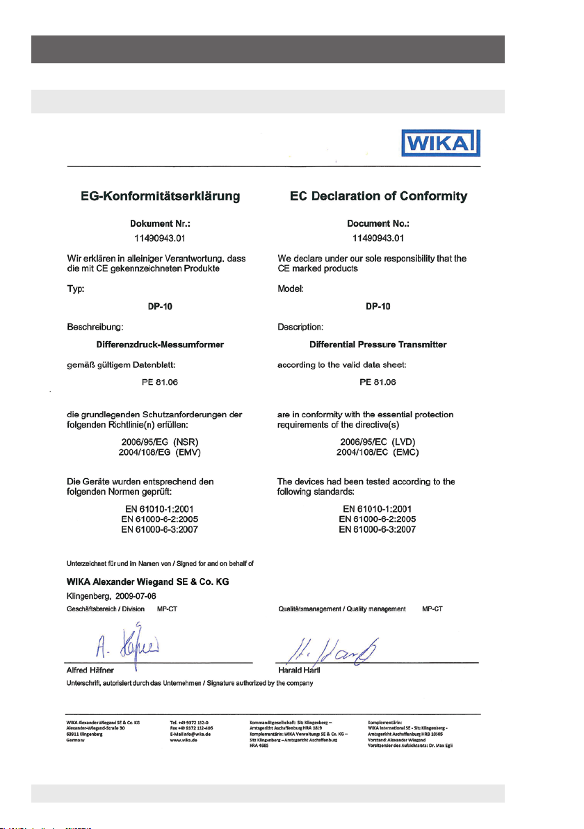
8. EG-Konformitätserklärung / EC Declaration of Conformity
8. EG-Konformitätserklärung / EC Declaration of Conformity
42
2333401 07/2009 GB/D/F/E
Page 43

8. Déclaration de Conformité CE / Declaración de Conformidad CE
8. Déclaration de Conformité CE / Declaración de Conformidad CE
2333401 07/2009 GB/D/F/E
43
Page 44

WIKA Global
All WIKA subsidiaries worldwide can be found online at www.wika.de.
Technical alteration rights reserved.
Technische Änderungen vorbehalten.
Sous réserve de modifications techniques.
Se reserva el derecho de modificaciones técnicas.
WIKA Alexander Wiegand SE & Co. KG
Alexander-Wiegand-Straße 30
63911 Klingenberg • Germany
Tel. (+49) 9372/132-0
Fax (+49) 9372/132-406
E-Mail
www.wika.de
44
info@wika.de
2333401.03 07/2009 GB/D/F/E
 Loading...