

Page 1
Operating instructions
Digital indicator model DI35-M GB
14053538.01 • 11/2012
Digital indicator model DI35
Page 2

Operating instructions model
DI35-M
GB
page 1 - 52
© 2010 WIKA Alexander Wiegand SE & Co. KG
All rights reserved.
WIKA® is a registered trademark in various countries.
Prior to starting any work, read the o perating instr uc tions !
Keep for later use!
2 WIKA operating instructions digital indicator DI35-M
Page 3

Contents
1 General information ................................................................................ 4
2 Safety ....................................................................................................... 5
2.1 Intended use ........................................................................................ 5
2.2 Personnel qualification......................................................................... 7
2.3 Special hazards ................................................................................... 7
2.4 Labelling / Safety marks ...................................................................... 8
3 Specifications .......................................................................................... 9
4 Design and function .............................................................................. 13
4.1 Short description ................................................................................ 13
4.2 Scope of delivery ............................................................................... 13
5 Transport, packaging and st orage ....................................................... 13
5.1 Transport ........................................................................................... 13
5.2 Packaging .......................................................................................... 13
5.3 Storage .............................................................................................. 14
6 Commissoning, operat ion .................................................................... 14
6.1 Mounting ............................................................................................ 14
6.2 Elec trical connection .......................................................................... 15
6.3 Function and operation description .................................................... 20
6.4 Configuration of the indicator ............................................................. 27
6.5 D escription of the measuring input .................................................... 29
6.6 Description oft he program numbers .................................................. 32
6.7 Program number ta ble ....................................................................... 40
6.8 Default values .................................................................................... 47
7 Maintenance and cleaning .................................................................... 47
7.1 Maintenance ...................................................................................... 47
7.2 Cleaning ............................................................................................ 47
8 Faults ..................................................................................................... 48
9 Dismounting, return and disposal ....................................................... 50
9.1 Dismounting ...................................................................................... 50
9.2 Return ............................................................................................... 50
9.3 Disposal ............................................................................................. 50
10 Appendix: Declaration of conformity ................................................... 51
Declarations of conformi ty can be found online at www.wika.com.
WIKA operating instructions digital indicator model DI35-M 3
Page 4

1 General information
1 General information
The instrument described in the operating instructions has been
designed and manufactured using state-of-the-art technology.
All components are subject to stringent quality and environmental
criteria during production. Our management systems are certified to
ISO 9001.
These operating instructions contain important information on handling
the instrument. Working safely requires that all safety instructions and
work instructions are observed.
Observe the relevant local accident prevention regulations and general
safety regulations for the instrument's range of use.
The operating instructions are part of the instrument and must be kept
in the immediate vicinity of the instrument and readily accessible to
skilled personnel at any time.
Skilled personnel must have carefully read and understood the
operating instructions, prior to beginning any work.
The manufacturer's liability is void in the case of any damage caused by
using the product contrary to its intended use, non-compliance with
these operating instructions, assignment of insufficiently qualified skilled
personnel or unauthorised modifications to the instrument.
The general terms and conditions, contained in the sales
documentation, shall apply.
Subject to technical modifications.
Further information:
- Internet address: www.wika.de / www.wika.com
- Relevant data sheet: AC 80.03
- Application consultant: Tel.: (+49) 9372/132-0
Fax: (+49) 9372/132-406
E-Mail: info@wika.de
4 WIKA operating instructions digital indicator DI35-M
Page 5
2 Safety
WARNING!
Explanation of symbols
WARNING!
... indicates a potentially dangerous situation that can result
in serious injury or death, if not avoided.
Information
... points out useful tips, recommendations and information
for efficient and trouble-free operation.
DANGER!
...identifies hazards caused by electric power. Should the
safety instructions not be observed, there is a risk of serious
or fatal injury.
2 Safety
Before installation, commissioning and operation, ensure that
the appropriate instrument has been selected in terms of
measuring range, design and specific measuring conditions.
Non-observance can result in serious injury and/or damage
to equipment.
Further important safety instructions can be found in the
individual chapters of these operating instructions.
2.1 Intended use
The digital indicator DI35-M is used for measurement and indication of sensor
signals, thermocouples and RTDs. Signals can be put out via an analogue
output for further processing.
The instrument has been designed and built solely for the intended use
described here, and may only be used accordingly.
WIKA operating instructions digital indicator model DI35-M 5
Page 6

2 Safety
Please read the following safety advice and the assembly before installation
and keep it for future reference.
If the instrument is transported from a cold into a warm environment, the
formation of condensation may result in the instrument malfunctioning. Before
putting it back into operation, wait for the instrument temperature and the
room temperature to equalise.
Notes on installation
There must be no magnetic or electric fields in the vicinity of the device,
e.g. due to transformers, mobile phones or electrostatic discharge.
Do not install inductive consumers (relays, solenoid valves etc.) near
the device and suppress any interference with the aid of RC spark
extinguishing combinations or free-wheeling diodes.
Keep input, output and supply lines separate from one another and do
not lay them parallel with each other. Position “go” and “return lines”
next to one another. Where possible use twisted pair. So, you receive
best measuring results.
Screen off and twist sensor lines. Do not lay current-carrying lines in the
vicinity. Connect the screening on one side on a suitable potential
equaliser (normally signal ground).
Do not install several devices immediately above one another or in an
extremely thermal isolated housing. Due to the internal heat dissipation
of the devices, the recommended ambient temperature can be
excessed.
The device is not suitable for installation in areas where there is a risk
of explosion.
Any electrical connection deviating from the connection diagram can
endanger human life and/or can destroy the equipment.
The terminal area of the devices is part of the service. Here electrostatic
discharge needs to be avoided. Attention! High voltages can cause
dangerous body currents.
Galvanic insulated potentials within one complex need to be placed on
a appropriate point (normally earth or machines ground). So, a lower
disturbance sensibility against impacted energy can be reached and
dangerous potentials, that can occur on long lines or due to faulty
wiring, can be avoided.
The fuse rating of the supply voltage should not exceed a value of 6A
N.B. fuse.
The manufacturer shall not be liable for claims of any type based on
operation contrary to the intended use.
6 WIKA operating instructions digital indicator DI35-M
Page 7
2 Safety
WARNING!
Keep unqualified personnel away from hazardous areas.
DANGER!
WARNING!
death or serious injury and material damage.
2.2 Personnel qualification
Risk of injury should qualification be insufficient!
Improper handling can result in considerable injury and
damage to equipment.
Skilled electrical personnel
Skilled electrical personnel are understood to be personnel who, based on
their technical training, knowledge of measurement and control technology
and on their experience and knowledge of country-specific regulations,
current standards and directives, are capable of carrying out work on
electrical systems and independently recognising and avoiding potential
hazards.
The skilled electrical personnel have been specifically trained for the work
environment they are working in and know the relevant standards and
regulations.
The skilled electrical personnel must comply with current legal accident
prevention regulations.
The activities described in these operating instructions
may only be carried out by skilled personnel who have
the qualifications described below.
2.3 Special hazards
Danger of death caused by electric current.
Upon contact with live parts, there is a direct danger of
death.
Electrical instruments may only be installed and mounted
by skilled electrical personnel.
Operation using a defective power supply unit (e.g. short
circuit from the mains voltage to the output voltage) can
result in life-threatening voltages at the instrument!
Do NOT use this product as safety or emergency stopping
device, or in any other application where failure of the
product could result in personal injury or material damage.
Failure to comply with these instructions could result in
WIKA operating instructions digital indicator model DI35-M 7
Page 8
2 Safety
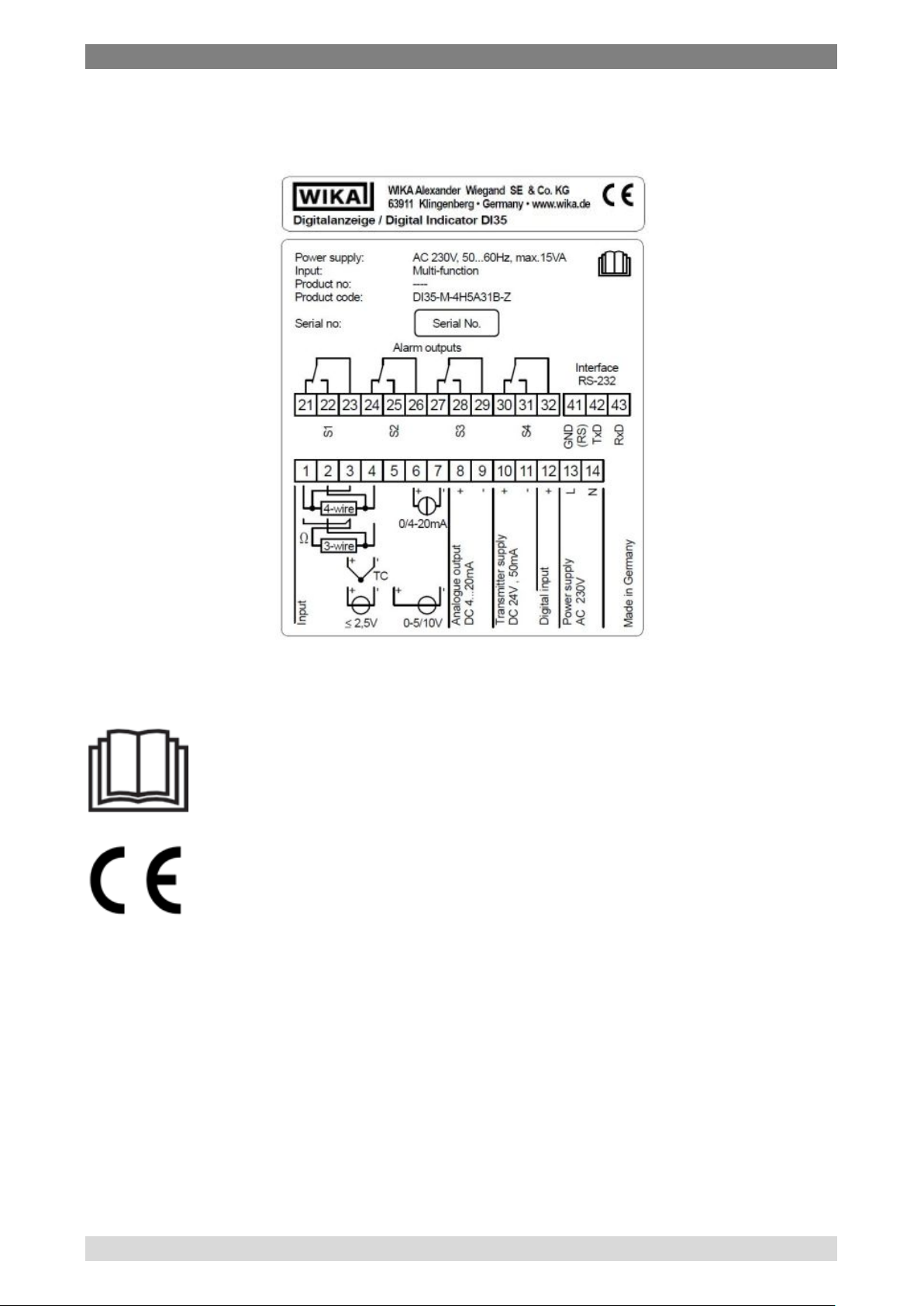
2.4 Labelling / Safety marks
Product label
Explanation of symbols
Before mounting and commissioning the instrument, ensure
you read the operating instructions!
CE, Communauté Européenne
Instruments bearing this mark comply with the relevant
European directives.
8 WIKA operating instructions digital indicator DI35-M
Page 9

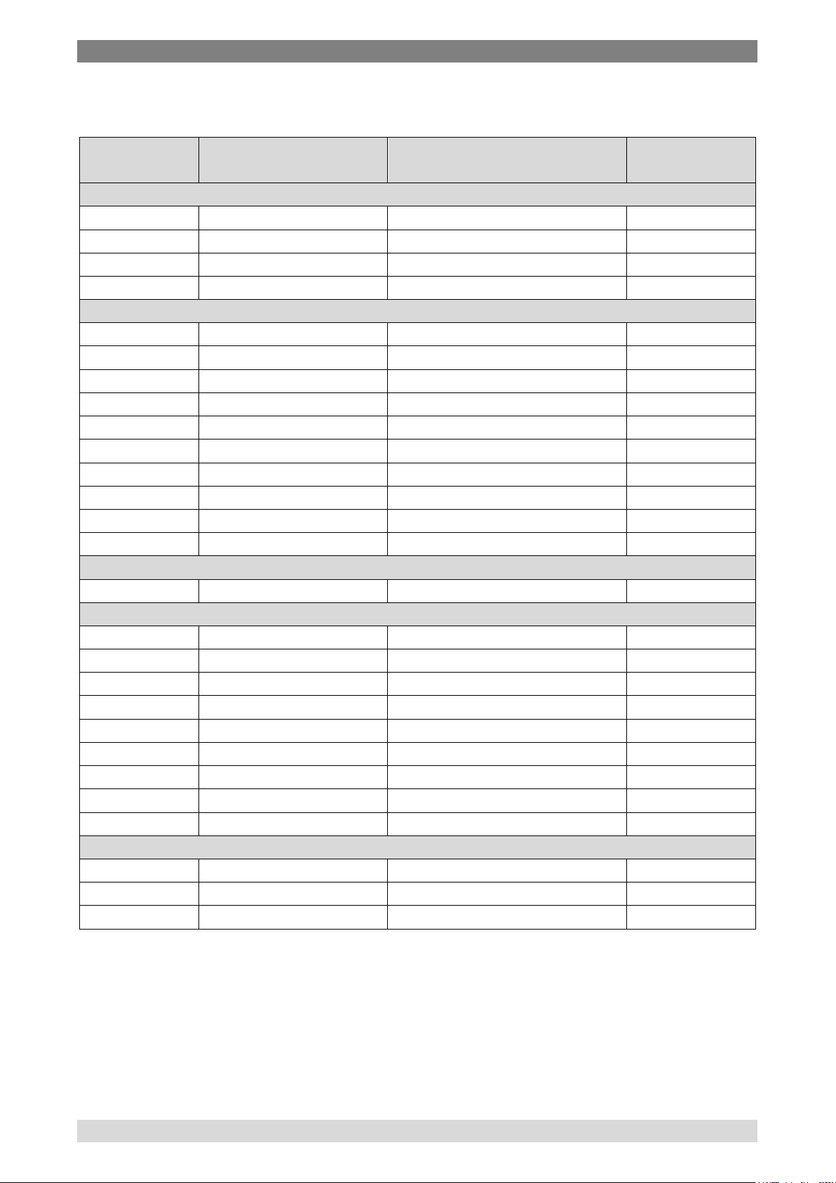
3 Specifications
Principle
7-segment LED, red, 5-digit, brightness
adjustable in 10 steps
Character size
14 mm
Indication range
-9999 … +99999
Indication time
0.1…10.0 seconds
Memory
EEPROM (independent of power supply), data
retension > 100 years
Input
Number and type
1 multi-function input
Input configuration
Selectable via terminal configuration and
programming
Accuracy
see following table
Temperature error
50 ppm/K,
at ambient temperature T < 20 °C or > 40 °C
Measuring principle
Sigma/Delta
Resolution
24 bit, (at measuring tim e 1 second )
Measuring time
0.02…10.0 sec
Totalizator time-error
max. 0.1% of totalizator value at integration
time > 1 min
{Transmitter supply}
DC 24 V, 50 mA
Power supply
AC 230 V, 50 / 60 Hz, ± 10 % or
Power supply galvanic insulated
Power consumption
max. 15 VA
Electrical connection
plug-in terminal,
wire cross-section up to 2.5 mm²
{Analogue output}
Number and type
1 analogue output (galvanic insulated):
0 ... 10 V (12-bit), load ≥ 10 kΩ
Error
0.1% in the range 20 °C ≤ Tu ≤ 40 °C, beyond
this value temperature error 50 ppm/K
Internal resistance
100 Ω (at measuring input 0…10 V)
3 Specifications
Specifications
Display
{AC 115 V, 50 / 60 Hz, ± 10 %} or
{AC 115 / 230 V, 50 / 60 Hz, ± 10 %
switchable} or
{DC 24 V, ± 10%}
4 ... 20 mA (12-bit), load ≤ 500 Ω or
0 ... 20 mA (12-bit), load ≤ 500 Ω or
WIKA operating instructions digital indicator model DI35-M 9
Page 10

3 Specifications
{Switching outputs}
number and type
2 or 4 change-over contacts (relays), fully
programmable
Load
AC 230 V, 5 A (ohmic load) or
DC 30 V, 2 A (oh mic load)
Switching cycles
0.5 * 105 at max contact rating
Characteristic data as per DIN EN 60255
{Serial Interface}
RS 232, selectable with or without galvanic
selectable with or without galvanic isolation
Protocol
manufacturer-specific ASCII
communication
9600 Baud, no parity, 8 data bits, 1 stop bit
Lead length
RS 232: max. 3 m
RS 485: max. 1000 m
Material
PC polycarbonate, ABS Blend, UL 94V-0,
black
Ingress protection
Front: IP 54, {IP 65};
Back: IP 00 (per IEC 60529 / EN 60529)
Weight
Approx. 450 g
Dimensions
96 x 48 x 148 mm (w x h x d) including plug-in
terminals
Mounting
snap-in screw element for wall thickness up to
50 mm
Operating temperature
0…60 °C
Storage temperature
-20…80 °C
Humidity
0…75 % relative humidity, non-condensing
EMC directive
2004/108/EC, EN 61326 emission (group 1,
application)
Low voltage directive
2006/95/EG, EN 61010-1
5 * 106 mechanically
Separation as per DIN EN 50178
isolation or
RS 485 (only for point-to-point connection),
Case
Permissible ambient conditions
CE conformity
class B ) and interference immunity (industrial
{ } Items in curved brackets are optional extras for additional price.
10 WIKA operating instructions digital indicator DI35-M
Page 11
3 Specifications
Input
signals
Measuring span
Measuring error in % of
the span
Inner
resistance
Current signals
0…20 mA
± 0.02 % ± 1 Digit
50 Ω
4…20 mA
± 0.02 % ± 1 Digit
50 Ω 0…5 mA
± 0.02 % ± 1 Digit
50 Ω 0…2 mA
± 0.02 % ± 1 Digit
50 Ω
Voltage signals
-1…10 V
± 0.01 % ± 1 Digit
150 kΩ -1…5 V
± 0.02 % ± 1 Digit
150 kΩ
-500…2500 mV
± 0.03 % ± 1 Digit
1 MΩ
-500…1250 mV
± 0.03 % ± 1 Digit
1 MΩ
-500…600 mV
± 0.03 % ± 1 Digit
1 MΩ
-300…300 mV
± 0.03 % ± 1 Digit
1 MΩ
-150…150 mV
± 0.03 % ± 1 Digit
1 MΩ
-75…75 mV
± 0.04 % ± 1 Digit
1 MΩ
-35…35 mV
± 0.06 % ± 1 Digit
1 MΩ
-18…18 mV
± 0.03 % ± 1 Digit
1 MΩ
PT100 (2-/3-/4-wire)
-200,0…850,0 °C
± 0.04 % ± 1 Digit
1 MΩ
Thermocouple
Typ L
-200…900 °C
± 0.06 % ± 1 K
1 MΩ
Typ J
-210…1200 °C
± 0.05 % ± 1 K
1 MΩ
Typ K
-250…1271 °C
± 0.05 % ± 1 K
1 MΩ
Typ B
-100…1810 °C
± 0.10 % ± 1 K
1 MΩ
Typ S
0…1767 °C
± 0.06 % ± 1 K
1 MΩ
Typ N
-250…1300 °C
± 0.06 % ± 1 K
1 MΩ
Typ E
-260…1000 °C
± 0.06 % ± 1 K
1 MΩ
Typ R
0…1767 °C
± 0.07 % ± 1 K
1 MΩ
Typ T
-240…400 °C
± 0.07 % ± 1 K
1 MΩ
Resistance (2-/3-/4-wire)
100 Ω
± 0.04 % ± 1 Digit
1 MΩ 1 kΩ
± 0.04 % ± 1 Digit
1 MΩ 10 kΩ
± 0.04 % ± 1 Digit
1 MΩ
Accuracy of input signals
The measuring errors are valid for ambient temperatures of 20…40 °C and a
measuring time of 1 second.
The datas for PT100 3-/4-wire are valid for a max. resistance of wire of 10 Ω.
WIKA operating instructions digital indicator model DI35-M 11
Page 12
3 Specifications
Input signal
Measuring time in seconds
Current signals
0.02…10.00
Voltage signals
0.02…10.00
PT100 (2-/4-wire)
0.04…10.00
PT100 (3-wire)
0.06…10.00
Thermocouple
0.04…10.00
Resistance (2-/4-wire)
0.04…10.00
Resistance (3-wire)
0.06…10.00
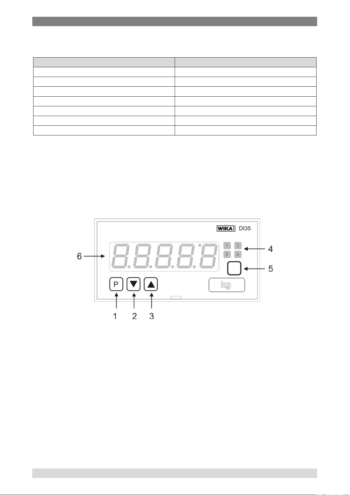
1: Program key
3: UP key
4: LEDs for alarm output
6: 7 segment display
Adjustable measuring times
For further specifications see WIKA data sheet AC 80.03 and the order
documentation.
Operating elements
2: DOWN key
5: Multi-function key
12 WIKA operating instructions digital indicator DI35-M
Page 13

5 Transport, packa ging and storage
4 Design and function
4.1 Short description
The digital indicator DI35-M is a multi-function and highly accurate digital
indicator. It has a multi-function input with 29 different calibrated input
configurations, which can be selected via the terminal configuration and by
the selection of the input signal in the instrument configuration. Furthermore
the possibility of sensor calibration and linearisation with up to 30 points is
offered.
The standard features are completed by the adjustable sampling rate and
display time as well as the input offset for the correction of zero offsets or
sensor drifts and TARA and HOLD function. The measured value or one of
the functions can be indicated and used as output signal.
As an option up to 4 fully programmable alarm outputs, an analogue output
signal, a serial interface and a transmitter power supply are available.
4.2 Scope of delivery
The scope of delivery is:
Indicator
2 fixing elements
Seal
Operating instructions
Cross-check scope of delivery with delivery note.
5 Transport, packaging and storage
5.1 Transport
Check instrument for any damage that may have been caused by transport.
Obvious damage must be reported immediately.
5.2 Packaging
Do not remove packaging until just before mounting. Keep the packaging as it
will provide optimum protection during transport (e.g. change in installation
site, sending for repair).
WIKA operating instructions digital indicator model DI35-M 13
Page 14

6 Commissoning, ope ration
WARNING!
5.3 Storage
Permissible conditions at the place of storage:
Storage temperature: -20 ... +80 °C
Humidity: 0 ... 75 % relative humidity (no condensation)
Avoid exposure to the following factors:
Direct sunlight or proximity to hot objects
Mechanical vibration, mechanical shock (putting it down hard)
Soot, vapour, dust and corrosive gases
Potentially explosive environments, flammable atmospheres
Store the instrument in its original packaging in a location that fulfils the
conditions listed above. If the original packaging is not available, pack and
store the instrument as described below:
1. Wrap the instrument in an antistatic plastic film.
2. Place the instrument, along with shock-absorbent material, in the
packaging.
3. If stored for a prolonged period of time (more than 30 days), place a
bag, containing a desiccant, inside the packaging.
Before storing the instrument (following operation), remove
any residual media. This is of particular importance if the
medium is hazardous to health, e.g. caustic, toxic,
carcinogenic, radioactive, etc.
6 Commissoning, operation
Please read the safety instructions and installation instructions in chapter 2
before installation and keep this user manual for future reference.
6.1 Mounting
Panel cut out: 92,0
Assembly grid: 120 mm horizontal, 96 mm vertical (recommended)
14 WIKA operating instructions digital indicator DI35-M
+0,8
mm x 45,0
+0,6
mm
Page 15
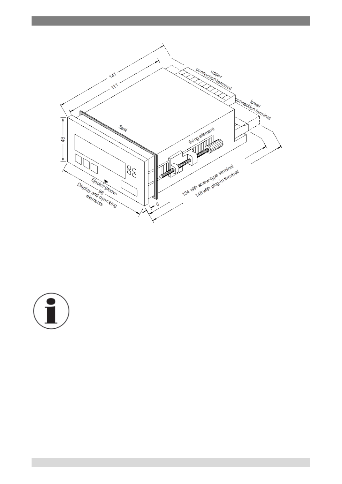
6 Commissoning, ope ration
1. After removing the fixing elements, insert the device.
2. Check the seal to make sure it fits securely.
3. Click the fixing elements back into place and tighten the clamping
screws by hand.
Information
The dimension symbols can be exchanged before
installation via a channel on the side!
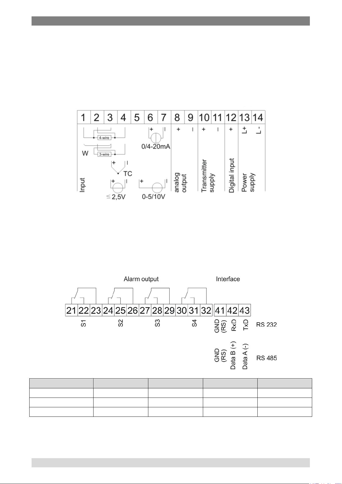
6.2 Electrical connection
All the necessary signals for operation are connected to the rear terminals.
The connecting terminals are designed as removable screw-type terminals
with a grid pitch of 5.08 mm. This makes it possible to connect wires of up to
2.5 mm².
WIKA operating instructions digital indicator model DI35-M 15
Page 16
6 Commissoning, ope ration
Relay 1 (S1)
Relay 2 (S2)
Relay 3 (S3)
Relay 4 (S4)
Normally closed
21
24
27
30
Normally open
22
25
28
31
Com
23
26
29
32
6.2.1 Terminal c onfi gura t ion Lower terminal connector
The power supply, the input signal, the transmitter supply and the analogue
output signal have to be connected to the lower terminal connector.
The mounting screws for the transmitter supply and the analogue output
signal are only available if these options have been chosen.
Upper terminal connector
The switching contacts (relays) and the serial interface have to be connected
to the upper terminal connector.
The mounting screws for the switching contacts and the interface are only
available if these options have been choosen.
16 WIKA operating instructions digital indicator DI35-M
Page 17

6 Commissoning, ope ration
Serial interface
RS 232:
The lines for the RS 232 interface must be connected 1:1, TxD to TxD and
RxD to RxD.
RS 485:
The RS 485 interface is connected via a shielded data line with a twisted pair.
At each end of the bus, a termination of the bus lines must be connected.
This is necessary to guarantee reliable data transmission on the bus. For this,
a resistance of 120 Ohm is inserted between the lines Data B(+) and Data
A(–).
CAUTION!
The potential reference can lead to a compensating current
(interface ⇔ measuring input) with a non-galvanic insulated
interface and can thus affect the measuring signals
WIKA operating instructions digital indicator model DI35-M 17
Page 18
6 Commissoning, ope ration
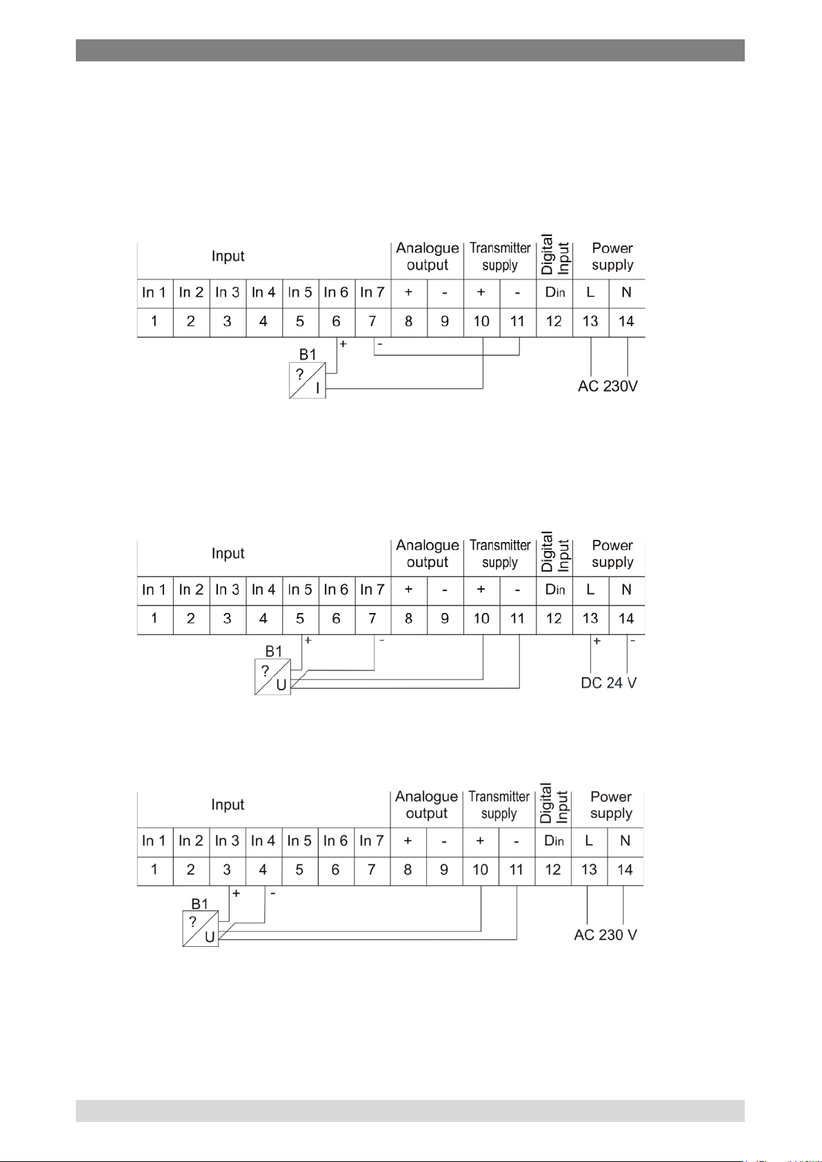
6.2.2 Connection examples
This section gives a few examples of practical connections. The different
examples can be combined.
a) 4…20 mA signal, 2-wire transmitter
b) 0…5 V/0…10 V signal, 3-wire tran smitter
The voltage drop on the transmitter supply wire is irrelevant, which is
why this can also be bridged directly on the indicator.
c) Voltage signal ≤ 2,5 V, 3 wire transmitt er
18 WIKA operating instructions digital indicator DI35-M
Page 19

6 Commissoning, ope ration
d) Resistance thermometer (eg. Pt100) or resistance, 2 wire
e) Resistance thermometer (eg. Pt100) or resistance, 3 wire
f) Resistance thermometer (eg. Pt100) or resistance, 4 wire
g) Thermocouple & digital input
WIKA operating instructions digital indicator model DI35-M 19
Page 20

6 Commissoning, ope ration
Name
Description
Program key [P]
With the program key, you can call up the
programming mode.
DOWN key [▼]
With the DOWN (de crease ) key, you can call up the
mode.
UP key [▲]
With the UP (increase) key, you can call up the MAX
memory or alter parameters in the programming mode.
Multi-function [O]
Multi-function for activating TARA function and HOLD
function; reset for MIN/MAX permanent
6.3 Function and operation description
6.3.1 Operation
The DI35-M has 4 keys ([P], [], [], [O]), with which you can parameterise
and call up various functions during operation.
programming mode or perform various functions in the
MIN memory or alter parameters in the programming
6.3.2 Switching on
Before switching on, check all the electrical connections to make sure they
are correct. On completion of the installation, the device can be switched on
by applying the supply voltage.
During the switching-on process, a segment test is performed for approx. 1
second, whereby all LED on the front (including setpoint LED) are triggered.
After this, th e type of software is indicated for approx. 1 second and then,
also for 1 second, the software version. After the starting procedure, the unit
changes to operation/display mode.
20 WIKA operating instructions digital indicator DI35-M
Page 21

6 Commissoning, ope ration
Parameter
Description
Alarm / Relay x
De-activiated, instananeaous value, MIN value, MAX
value
Threshold
Threshold / Switch-over threshold
Hysteresis
Width of window between switching threshold
Working principle
Operating current / quiescent current
Switch-on delay
Time between reaching the threshold and the
resultant switching on of the relay.
Switch-off delay
Time between reaching the threshold and the
resultant switching off of the relay.
Alarm confirmation
Switch-on or switch-off interlock and rejection at
activated digital input or multi-function key
6.3.3 General functi ons MIN/MAX memory
The measured minimum and maximum values are saved in a volatile memory
in the unit and get lost when the unit is switched off.
You can call up the contents of the memory by pushing (less than 1 second)
the [▲] or [▼] key. The relevant value is indicated for approx. 7 seconds. By
briefly pressing the same key again, you will return immediately to the display
mode.
[▲] dis playing of MAX value
[▼] dis playing of MIN value
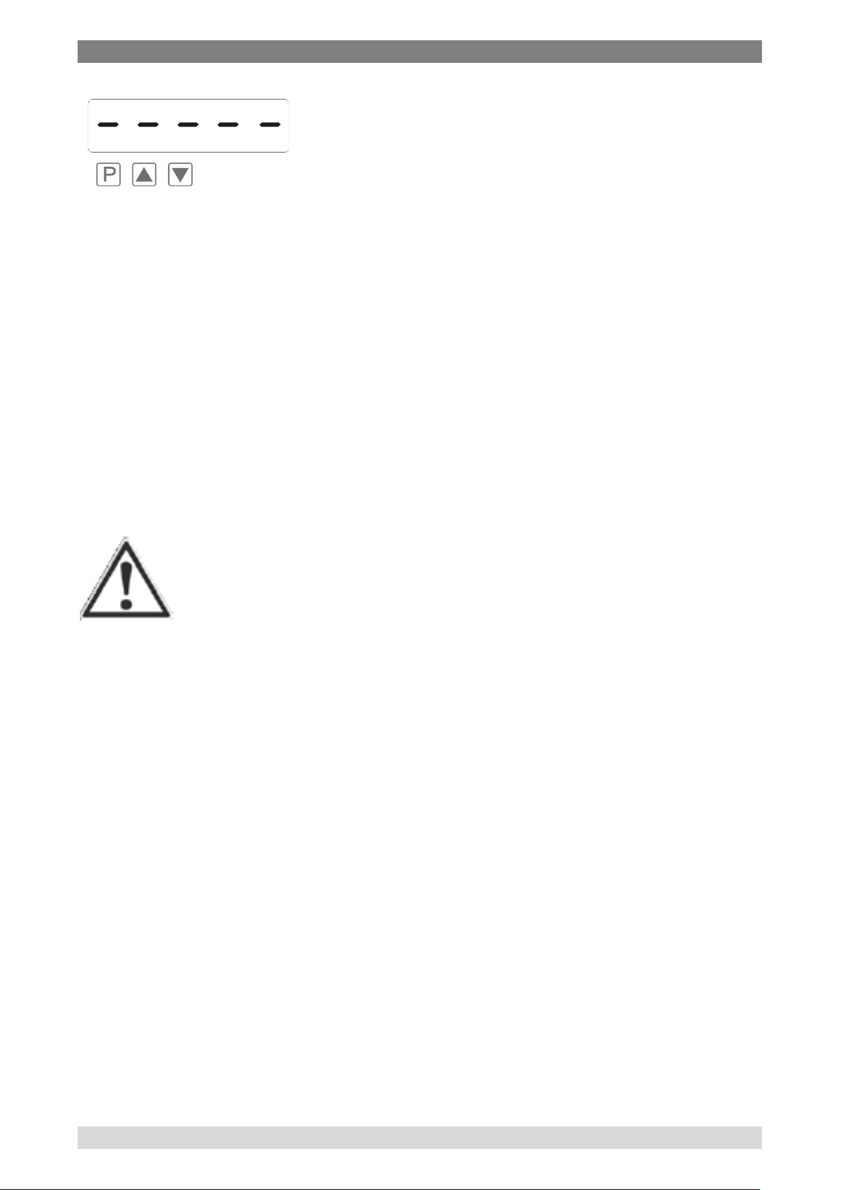
You can erase the value shown in the display by simultaneously operating the
[▲] and [▼] keys. The erasure is acknowledged by horizontal bars.
Information
The content of the memory will be lost with switching-off of
the device.
6.3.4 Descripti on of t he al ar m output s
With the aid of the LED next to the 7‑segment display, you can view the
switching state of the relays. An active relay is indicated by the relevant LED
lighting up.
Working principle
The alarm outputs have the following properties with regard to their switching
properties:
value, Hold value, sliding average value, totalizator
WIKA operating instructions digital indicator model DI35-M 21
Page 22

6 Commissoning, ope ration
Operating current
The alarm is off below the
threshold and on when
reaching the threshold.
Quiescent current
The alarm is on below the
threshold and switched off
on reaching the threshold.
Switch-on delay
The relay is on e.g. 10
seconds after reaching the
threshold. Briefly exceeding
the threshold does not lead to
the relay being switched on.
The switch-off delay functions in a similar manner, in other words it keeps the
alarm output switched on until the parameterised time has elapsed.
22 WIKA operating instructions digital indicator DI35-M
Page 23

6 Commissoning, ope ration
Modus
Actuate value
0
none
1
Instaneaous value
2
Minimal value
3
Maximal value
4
HOLD value
5
Sliding average value
6
Totalizator value
Allocation of the alarms to a certain actuate value
As it is not always desired that alarms follow the operating mode, the outputs
can be assigned to the minimal-/maximal value or any other value. Therefor
the adjustable value range is assigned to the according program number
(PN60, PN70, PN80 and PN90).
Alarm confirmation
If one wants to display interim occured alarms, the self-acting switching-on or
switching-off can be blocked. Therefore the confirmation of the according
setpoints 1-4 must be assigned to the digital input or the multi-function key
under program numbers 67, 77, 87 and 97.
Information
Alarm status will get lost by voltage drop!
Optical response, flashing display
If one or some thresholds are broken, the flashing of the alarm LED can
amplify the optical response by assignment of the threshold (PN59) to the 7
segment display.
Example: The threshold for flashing of the display is set at setpoint 2. If
setpoint 1 is exceeded and set point 2 is not, the set point LED
1 lights up permanently. If setpoint 2 exceeds the threshold, the
7-segment displ a y will star t to flash, setp o i nt 1 will light up
permanently and set point LED 2 will flash. The flashing
enhances the optical response and the operator sees
immediately that an important threshold has been exceeded
with this unit.
WIKA operating instructions digital indicator model DI35-M 23
Page 24

6 Commissoning, ope ration
6.3.5 Analog output
The optional analogue output is used for the transduction of a measuring
value, supported by a standard signal of 0…10 V or 0/4…20 mA.
The analogue output is parameterised via the two program numbers PN20
“final value (fullscale)” and PN21 “initial value (offset)”. At the initial value, the
value is set at which the analogue output transmits the minimal value (0 V or
0/4 mA), and with "Full scale", the value at which the output transmits its
maximum (10 V or 20 mA).
By this means it is possible to re-scale the input signal of a transducer or
even to convert it into another standard signal. The analogue output can be
de-activated via the actuate value PN22, as well as set on the active
measuring value, MIN value, MAX value, HOLD value, sliding average value
or totalizator value.
The analogue output is updated within the cycle of the measuring time. At a
high measuring rate, smaller cycle fluctuations of some milli-seconds are
possible.
6.3.6 Digital input / multi-function key
In combination with the digital input (via terminal) and/or the multi-function
key at the front, functions like e.g. HOLD, TARA, MIN/MAX permanent or
totalizator function, can be actuated respectively set back. The digital input is
available in combination with the option sensor supply or via an external DC
24 V-signal. The multi-function key at the front of the device can be activated
by keypress.
HOLD function
The HOLD function is a static signal and will be activated via the digital input
or the multi-function key. With activated HOLD the lastly given measuring
value remains and is by deactivation permanently overwritten by the
measuring value recording. With this function a test state can be recorded
beyond a specific period, so that this device can be used for control in run
production, too.
Information
HOLD value gets lost with re-start!
24 WIKA operating instructions digital indicator DI35-M
Page 25

6 Commissoning, ope ration
TARA function
The TARA-Function can be activated by multi-function key, digital input or
with boot-up, the display value is then on the tare value.
This function is only done once, after actuation of the desired trigger and has
to be taken back before a new alignment.
MIN/MAX permanent
To measure a MIN-/MAX-value the display can be set back by the display
mode (PN15) in a way, that it only shows the minimal or maximal measured
value. The value can be reset by the multi-function key and/or the digital
input.
Information
MIN/MAX value get lost with re -start!
Totalizator functi ons
With the totalizator, the measured display value can be integrated or
accumulated over a time. The accumulated time-frame depends on the preset
measuring time (PN14). With this function e.g. a volume over the current
discharge can be recorded. So this function is qualified for the dose of fill-up
quantities in conjunction with relays. The mileage section can be detected by
the measured speed.
The cumulative value:
can be parameterized on different time bases and dimensions (e.g. for
volume, liter, m³, km³, …).
can be directed to the display and outputs as a default display value.
can be reset by a parameterized signal as counter reset (PN185) or by
the counter value (PN184).
is saved in the device even beyond a voltage drop by long-lasting
memory. A data loss of max. 30 minutes can occur in case of a voltage
drop.
WIKA operating instructions digital indicator model DI35-M 25
Page 26

6 Commissoning, ope ration
Parameter
Description
PN34 = 0
Standard mode in which the unit only replies if called on to do
current measuring value can be recalled via commando “A ↵ “.
PN34 = 1
Transmission mode in which the measurements are
measuring time.
6.3.7 Serial interface RS232 / RS485
If the DI35-M has an serial interface, the device can be programmed via this
interface. The interface is available as an option, the basic version is without
an interface.
Operating mode:
The interface can be operated in various modes which can be parameterized
via the PN34 (interface behavior).
so. This mode is used only for configuration. Furthermore the
transmitted via the serial interface cyclically with the set
The transmission mode is interrupted on receipt of “> ↵“ and the unit changes
to standard mode. To change back to transmission mode, the display must be
restarted, either by entering the command “S ↵“ or by switching the device off
and on.
With the transmission mode, the display value is transmitted via the interface
in ASCII format. Minus signs and decimal points are also transmitted so that
the output can be displayed directly on a terminal or processed by a SPS.
Zeros at the front are suppressed during transmission. With an over or
underflow, the display transmits horizontal bars (hyphens) "- - - - - ↵".
If there is a broken wire detected at temperature measurement "Lbr ↵ " will be
sended. A choosen dimension ("°C" / "°F") will be ignored at transmission.
Examples: "0.00 ↵" ; "-9.99 ↵" ; "999.99 ↵" ; "-123.45" ; "- - - - - ↵“ ; "Lbr ↵"
With the aid of this simple protocol structure, the display data can be
transferred very easily to a PC etc. and further processed there. In the
simplest case, a terminal program from the operating system is sufficient to
store the received data in a file .
Configuration of the devic e vi a inte rf a c e
For configuration the set-up tool PM-Tool can be used. As the communication
is a straight point-to-point connection. The baud rate is set to 9600 baud, with
8 databits, without parity and one stopbit.
Configuration is performed by transmitting ASCII symbols.
26 WIKA operating instructions digital indicator DI35-M
Page 27
6 Commissoning, ope ration
Example:
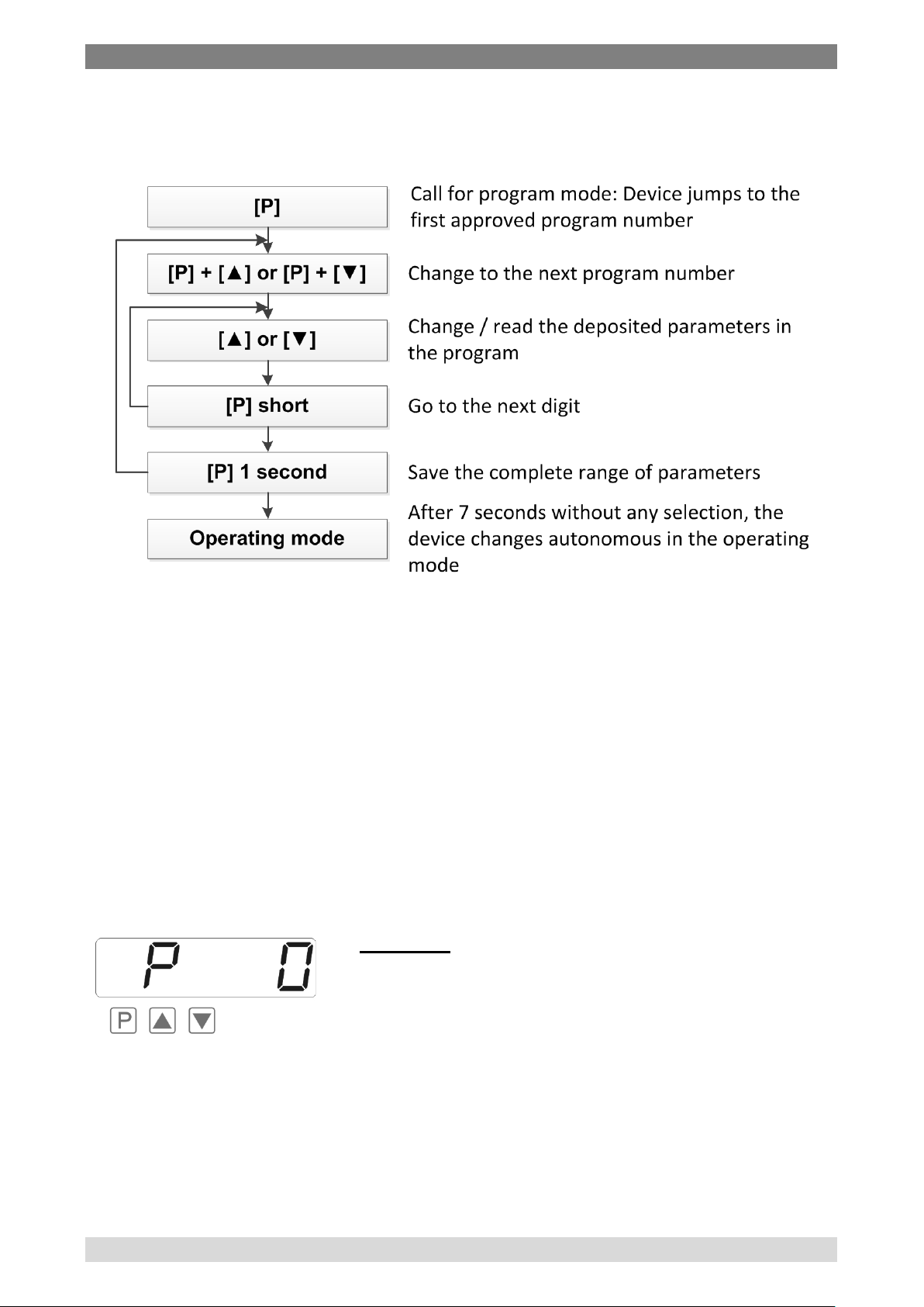
6.4 Configuration of the indicator
Functional diagram of programming via key pad:
Description of the progr a m numbers
In the display, the program numbers (PN) are shown, right-justified, as a 3digit number with a P in front of them:
Programming procedure
The entire programming of the DI35 is done by the steps described below.
Change to programming mode
Push the [P] key to change into programming mode. The unit goes to the
lowest available program number.
If the programming lock is activated, the key must be pushed for at least 1
second.
Displaying of program number 0, after pushing
the [P] key.
Change between program numbe rs
To change between individual program numbers, hold the [P] key down and
push the [▲] key for changing to a higher program number or the [▼] key for
changing to a lower number. By keeping the keys pushed, e.g. [P] & [▲], the
display will begin, after approx. 1 second, to automatically run through the
program numbers.
WIKA operating instructions digital indicator model DI35-M 27
Page 28

6 Commissoning, ope ration
Example:
and 7 do not need to be changed.
Change to the parameter
Once the program number appears in the display, you can push the [▼] or
[▲] key to get to the parameters set for this program number. Es erscheint
für einen kurzen Moment „SCALE“ in der Anzeige. The currently stored
parameters are displayed.
Changing a parameter
After changing to the parameter, the lowest digit of the respective parameter
flashes on the display. The value can be changed with the [▲] or [▼] key. To
move to the next digit, the [P] key must be briefly pushed. Once the highest
digit has been set and confirmed with [P], the lowest digit will begin to flash
again.
Saving of parameters
All parameters must be acknowledged by the user by pushing the [P] key for
one second. The changed parameters are then taken over as the current
operating parameters and saved in the EEPROM.
This is confirmed by horizontal bars lighting up in the display.
All the newly entered data are confirmed by the unit. If no confirmation is
received, the relevant parameters have not been saved, e.g. confirmation of
parameters:
The 0 is flashing this is the lowest digit and asks
if you want to change it. Let us assume the figure
is to be changed from 75,640 to 75,000.
Briefly push the [P] key to move to the next digit.
The 4 begins to flash. Change the figure by
pushing [▲] or [▼] to change the digit from 4 to
0. Briefly push the [P] key to move on to the next
digit. The 6 begins to flash. Change the digit by
pushing [▲] or [▼] to move the 6 to a 0. Briefly
push the [P] key to move to the next digit. The 5
Information
If a minus shall be displayed for negative values, the leftest
digit of the 7 segment display has to be activated (it blinks).
The minus can be activated with the [▼] key.
28 WIKA operating instructions digital indicator DI35-M
Page 29
6 Commissoning, ope ration
CAUTION!
Changing from programming to operating mode
If no key is pushed in the programming mode for about 7 seconds, the unit
will return automatically to operating mode. Before „SAVE“ will be displayed
until the next measuring value is displayed.
6.5 Description of the measuring input
Universal measuring input
The DI35-M is equipped with a universal measuring input that enables the
signals from all kinds of different sensors to be measured direct. So that the
unit can work according to the signal generated by the sensor, the input must
be configured. The basic parameter is always set under PN0.
Setting / Calibration of the meas uring input
All the units are calibrated in the factory, whereby offset and full scale have
been saved for the various measuring ranges. Via terminal connections and
the choice of the measuring input under PN0, different types of input signals
can be worked up.
Factory calibration c urrent / voltage under PN0 = 1…12
For these parameters, new scaled display values can be allocated which are
used for scaling the measurement on the display. For the offset, an input
signal of 0 is assumed and for full scale, the specific full scale of the
parameterized measuring range.
For parameterization, no sensor signal has to be applied because stored
values are used. Because of the differing input signals, the corresponding
input configuration must be parameterized via PN0.
For the sensor signal with 4...20 mA, for example, PN0 = 3 has to be
parameterized.
For the unit to function correctly, it is absolutely essential that
the right sensor is parameterized under program number 0. If
a wrong sensor is parameterized there, the operating
behavior may be impaired.
WIKA operating instructions digital indicator model DI35-M 29
Page 30

6 Commissoning, ope ration
Temperature measurement PN0 = 13…29
For the temperature measurement, the scaling cannot be changed by the
user and is only determined from the standardized sensor range. Sensorcaused variations can be balanced by offset shift (PN5) on the characteristic
line.
Sensor calibration for resistance / current / voltage PN0 ≥ 30
With the sensor calibration, the unit can be calibrated or set up directly via the
sensor signal or via a calibrator. For this, the measuring signal must be
connected to the input of the unit. The respective display value (SCALE) must
then be saved under the program number PN1 (full scale) and PN2 (offset).
The sensor signal is measured via the factory parameter and displayed as
current or voltage. A measurement must be started by shortly pushing the [P]
key. Through this process with two calibration points, the unit is matched up
with the measuring section. For more far-reaching adjustments to the
characteristic line of the sensor, a linearization can be activated.
At the resistance measurement, only the display value (SCALE) is
parameterised. The adjoining sensor signal (INPUT) will not be displayed, but
directly absorbed unit-intern. For linearization of the parameter at least PN1
(final value) or PN2 (zero point) must be preset.
Linearization PN100
The DI35-M offers the possibility to linearize, with up to 30 additional
setpoints, non-linear sensors for the display of the measuring values and their
subsequent processing (analog output).
The number of the desired setpoints is determined under PN100. Be aware of
choosing the one that makes th e m ost sens e, as it ca n lead to a ma lfunction
of the device in case of no adjustment.
Approach to sensor calibrat ion PN0 ≥ 33
To program e.g. 5 additional calibration points, 5 must be entered under
PN100.
Subsequently, for each of the calibration points, the voltage/current must be
applied to the unit and the respective display value programmed under the
following program numbers PN101 – PN105.
The sensor signal must be consistently parameterized. A gap of at least +1
digit to the previous display value must be adhered to, otherwise the input will
be refused and no confirmation of the saving will be given.
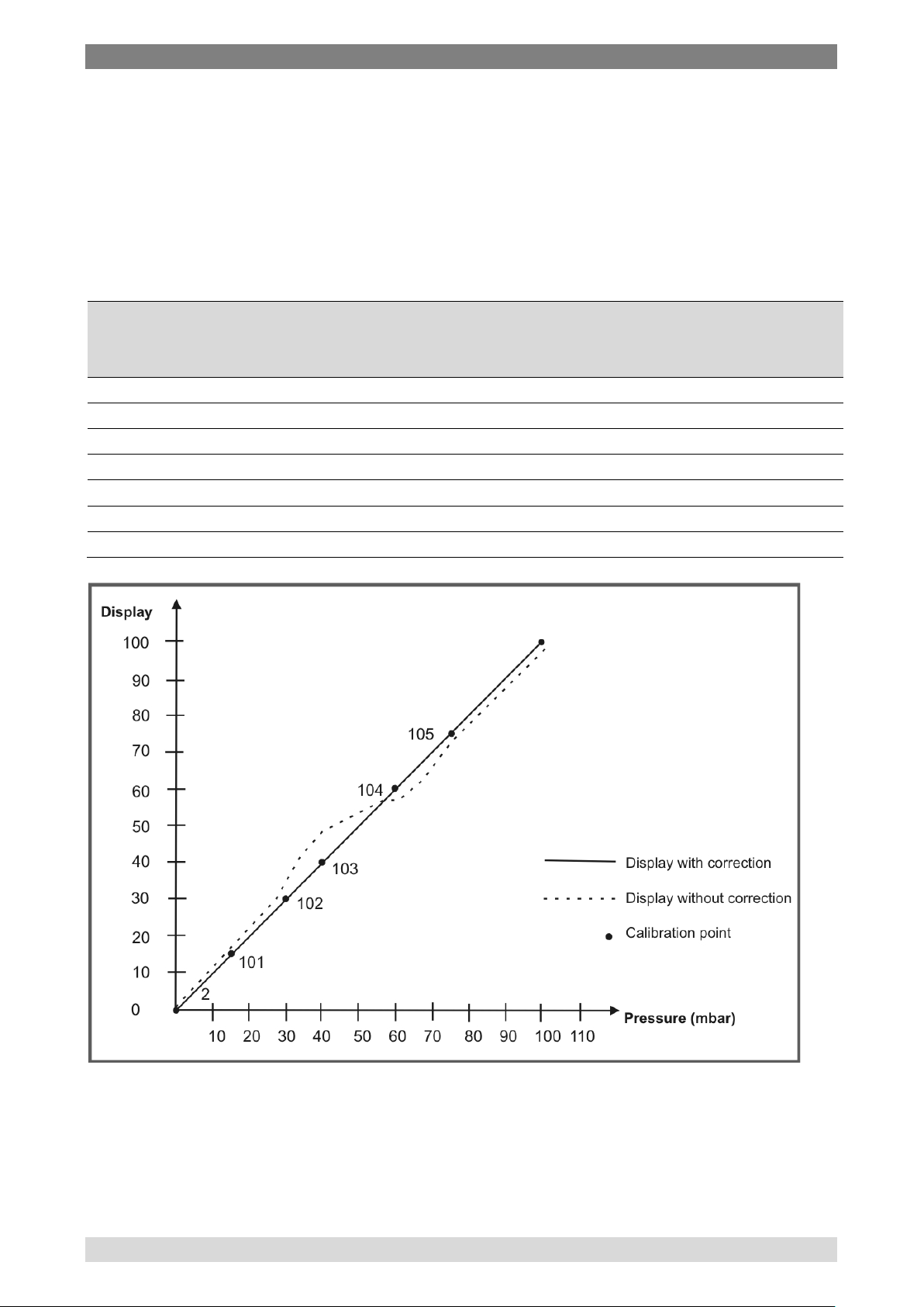
Example: Linearization of a pressure transducer for 0...100 mbar with an
output of 0...20 mA. The display value before correction can be
either calculated from the known characteristic line of the
transducer or be determined empirically.
30 WIKA operating instructions digital indicator DI35-M
Page 31
6 Commissoning, ope ration
Calibration
Pressure
Output
(mA)
display before
(IN)
Desired
(OUT)
2 0 0.5
2.5
0.0
101
15
3.3
16.5
15.0
102
30
6.2
31.0
30.0
103
40
9.2
46.0
40.0
104
60
11.4
57.0
60.0
105
75
14.7
73.5
75.0
1
100
20
100.0
100.0
The non-linear range is between 0...75 mbar. For calibration
point 101, this means:
A pressure of 15 mbar, the transducer delivers 3.3 mbar instead
of the optimum value of 3.0 mbar. As 20 mA in the display
corresponds to 100.0 mbar, 3.3 mA in the display corresponds
to 16.5 mA before the correction. To correct this error, enter
“15.0“ at PN101.
point (PN)
(mbar)
transmitter
correction
display
WIKA operating instructions digital indicator model DI35-M 31
Page 32

6 Commissoning, ope ration
Proceeding with factory calibration PN0 ≤12
With adjusted factory calibration a linearization without connection of the
sensor signal can be presetted. Therefore the number of the desired
setpoints needs to be filled in under PN100, to subsequently relate the
display values to a certain measuring signal.
Starting on setpoint (PN101) the display value (SCALE) and subsequently the
according measuring signal (INPUT) need to be programmed. Both inputs are
saved by pushing the [P]-key (for approx. 1 sec).
6.6 Description of the program numbers
The DI35-M device has a default configuration ex factory, where a 0…10 V
input signal is changed into a display value of 0…10000. For devices, where
the pre-configuration is unknown, a reset on the default parameter should be
done (see chapter “6.8 Default values”). Otherwise unwanted reactions of the
device can occur due to foreign settings.
The devices do have a digital input, with which some functions like e.g.
HOLD, TARA, or MIN/MAX can be actuated.
PN0: Measuring input
For the basic configuration of the unit, you must parameterize the right
measuring input for your application under PN0. There is a choice of various
inputs in the program number table (chapter „6.7 Program number table“).
PN1 and PN2: Scaling
The two program numbers 1 and 2 serve to scale the display; with these two
parameters, the offset and full scale are parameterized . For each setpoint
there is a SCALE–value and a INPUT–value. The SCALE–value indicates the
desired display value. The according measuring signal is determined by the
INPUT–value. In case of factory calibration the desired current or voltage
value is preset. If a sensor calibration is demanded, a measurement can be
actuated by a short pushing of the [P]-key. Before the saved current / voltage
value is visible. All inputs need to be confirmed by pushing the [P]-key for
approx. 1 second; the device confirms the correct take-over with 5 vertically
bars in the display.
PN3: Decimal point
By changing this parameter, the position of the decimal point in the display is
changed. With temperature measurements, the physical unit °C or °F can
also be added.
32 WIKA operating instructions digital indicator DI35-M
Page 33

6 Commissoning, ope ration
PN5: Offset shift / Zero point shift
With this parameter it is possible to carry out a parallel shift of the
parameterized characteristic line. This may be necessary if, for example, a
pressure sensor ages over the course of time and a shift in the zero point
occurs. With the parallel shift, the sensor can be adjusted back to the zero
point. Another application would be to parameterize a certain tank level to
zero and have any deviation from this level displayed.
With the offset it does not matter whether the original characteristic line has
been programmed by the user with PN1, PN2 or PN101...130 or whether it is
the characteristic line of a temperature sensor. The value parameterized
under PN5 is added to the original display value.
Example: If, for example, a temperature sensor shows approx. 3°C
instead of 0°C, you can compensate for this deviation by
changing the value under PN 5 from 0 to ‑3.
If the comparison metering point is turned off for the thermocouple, the
comparison metering temperature can be preset manually. This parameter
can be changed directly by taring, if it has been actuated by a configurated
incident (see PN8).
PN6: Thermocouple reference junction
The thermocouple reference junction is only available for thermocouples and
can be activated or deactivated under PN6. Deactivation may be useful
where the interchange point is kept at a very constant level or the
temperature constitutes the direct relationship to the process. In this case the
wiring to the measuring device can be conducted in simple wiring copper.
PN7: Setpoint value f or taring
By actuation of the taring, the display value is set on the taring value. This
means the offset / zero point is shifted in a way that the display value is
equivalent to the taring value.
PN8: Actuation f or taring
During taring, the instantaneaus value is set on a demanded setpoint value,
which is configurated under PN7. The difference between setpoint value and
actual value is safed as Offset PN5 in the device.
The following operating modes, which are adjustable at PN8, are available:
WIKA operating instructions digital indicator model DI35-M 33
Page 34

6 Commissoning, ope ration
PN8 =
Actuation for taring
0
none
1
Digital input active, longer than 3 seconds
2
Multi-function key actuated for longer than 3 seconds
3
Digital input or multi-function key active for longer than 3 seconds
4
Taring at boot-up
5
Taring at boot-up and with digital input
6
Taring at boot-up and with multi-function key
7
Taring at boot-up, digital input and multi-function key
8
Taring with activated digital input for activation period
9
Fast taring on digital input
10
Fast taring on multi-function key
11
Fast taring on digital input or multi-function key
The taring can be called off by programming of the PN5 offset shift on the
value zero.
A special form is taring PN8 = 8: the taring is not saved in PN5 offset shift,
but charged temporarily for the duration of the activated digital input. The old
tara value gets lost by a boot-up.
The display shows „ooooo“ for approx. 1 second to confirm the taring. Taring
is done only one time after actuation of the desired activator. For a anew
calibration the signal for the activation of the taring must be cancelled.
If the MIN/MAX value reset is programmed on the same activator as the
taring, then after taring a MIN- / MAX value reset takes place, too.
Furthermore the taring can be watched very well as the instantaneous value
is shown directly before and after taring.
PN12: Sliding average value
The complete average time is a results of the product or a multiplication of
time and recorded average value PN14 x PN12. If one wants to see this
result in the display, the display mode PN15 needs to be programmed parallel
on this result. This must be pointed out with an optional analogue output or
with the relays, too.
PN13: Display time
The display time is the interval at which the display is updated. The longer the
time between two display cycles, the calmer the display. The eye perceives a
display time of 1 second as very pleasant.
PN14: Measuring time
The DI35-M performs an averaging process by calculating an average from
several measurements taken during the measuring time (1/measuring time =
Samples/s). For most applications, a measuring time of 0.20 to 1.00 seconds
is suitable .
34 WIKA operating instructions digital indicator DI35-M
Page 35

6 Commissoning, ope ration
CAUTION!
short measuring time.
PN15=
Description
1
Instantaneous value: Operational mode „instantaneous value“
is displayed.
2
Minimal value display: In this operational mode, the smallest
(switching-on) or by the digital input/ multi-function key.
3
Maximal value display:
digital input/ multi-function key.
5
Sliding average value: The complete average time is a results
analogue output or with the relays, too.
6
Totalisator value: In operation mode „Totalisator value“, the
to be displayed in a individual adjustable dimension.
7
Absolute value: In operation mode „absolute value“ the display
connection, without consideration of a previous taring.
8
Trigger mode: In operation mode „trigger mode“ the
The updating of other functional components (analogue
output and relay) is carried out cyclically with the set
measuring time. If the measuring time is set very short, it is
possible that there will be jumps in the analogue output in the
case of a noisy signal or a brief switching of the relay. When
selecting the measuring time, it should be borne in mind that
the MIN / MAX memory receives its values on the basis of the
set measuring time. Should the peaks of a turbulent signal be
recorded, it may certainly be worthwhile to choose a very
PN15: Display mode
The device supports several operational modes, which are selectable under
PN15.
is equal to the standard display, where the last measured value
occurred display value, since the last minimal value reset, is
displayed. The minimal value reset is actuated by boot-up
In this operational mode, the largest occurred display value,
since the last maximal value reset, is displayed. The maximal
value reset is actuated by boot-up (switching-on) or by the
of the product or a multiplication of time and recorded average
value PN14 x PN12. If one wants to see this result in the
display, the display mode PN15 needs to be programmed
parallel on this result. This must be pointed out with an optional
totalisator- / sum value is displayed. With this value by means of
an active flow rate, a volume about the time can be collected.
As this time can be very long (approx. 1 year), the value needs
shows the value that has been measured since voltage
WIKA operating instructions digital indicator model DI35-M 35
Page 36

6 Commissoning, ope ration
instantaneous value is only transmitted on the display by a
multi-function key.
PN16 =
Activator for MIN / MAX value reset
0
None
1
Digital input active, for longer than 50 ms
2
Multi-function key pressed for longer than 50 ms
3
Digital input or multi-function key active, for longer than 50 ms
4
Taring function
increasing shoulder via the digital input or by activating of the
PN16: Activator for MIN / MAX value reset
After boot-up the MIN / MAX values are automatically set back on the
instantaneous value. To set back minimal- /maximal values even during
operation, 3 additional escapements are available.
The value reset is only shown shortly after actuation of the digital input or
multi-function key by 5 horizontal bars (“ - - - - - “) for 0.5 se co n ds. After that
the instantaneous value is shown as long in operating mode MIN / MAX value
display, as the activator is taken back. This way the instantaneous value can
be watched for a longer time.
If the value reset ought to be done during taring, then there is no report in the
display.
During value reset only the MIN/MAX value that presently shown in the
display is set back!
PN18: Zero point suppression
The zero point suppression offers the possibility of masking an area around
zero for displaying a value of zero. In the program number the amount is
parameterized which is then effective in both the positive and the negative
directions. This may be necessary if, for example, a number of revolutions is
being measured by an analogue sensor and has a drift around zero. If the
signal changes slightly when the motor comes to a standstill, a speed of zero
is still indicated. In addition, slightly negative rpms are suppressed.
PN20, PN21 and PN22: Analogue out put
The parameters of the analogue output refer to the scaling of the display and
are cyclically updated with the measuring time. With PN22 = 0 the analogue
output can be de-activated, whereas it remains on its initial value after a restart of the device.
The analogue output can be related to all possible values that are recorded in
the device. For further information please see chapter „6.3.5 Analogue
output“ or chapter “6.7 program number table”.
36 WIKA operating instructions digital indicator DI35-M
Page 37

6 Commissoning, ope ration
Userlevel PN 52 =
0 1 2 3 4 5 6 7 8
Access to
PN
Display brightness
19
• • • • • • • • •
Programming lock
50
• • • • • • • • •
Serial number
200
• • • • • • • • •
Setpoint threshold values
61, 71, 81, 91
• • • • • • •
•
Setpoint parameters
59…95
• • • • • • •
Interface parameters (option)
32…34
• • • • •
Analog output parameter (option)
20…22
• • • • •
Measuring input parameters
0…18
• • •
Linearization para met e r s for
measuring input
100…130
• • •
Authorization code
51 •
Userlevel
52
The inital and final value is always displayed without comma. The
demonstration of the measuring value in the display is taken as base, so with
a demonstration of e.g. 6.400 the final value can be parameterized by 6400
on this display value.
PN34: Interface behavior
The current display value can be sent by the optional interface. In standard
mode PN34 = 0 the display stays passive and expects data from the bus.
This operation is used for the configuration of the display. For slower actions
the instantaneous measuring value can be actively asked for by command. In
sending mode PN34 = 1 the displays sends actively in cycle of the measuring
time the current measuring value. For further information please see chapter
„6.3.7 Serial Interface RS232/ RS485“.
PN50 to PN52: Security setting , user level
With the parameters in the security settings, access to the program numbers
is regulated through the setting of various user levels. The user levels divide
the access into various levels. The user is only given access to the settings
authorized by the system operator, such as the setting of thresholds. The
lower the figure for the user level given under PN52, the lower the level of
security of the unit parameters against user intervention .
•
Userlevel contains program number x
The user level 1,3, and 5 are reserved. With rising userlevel, the number of
for the user unlocked parameters decreases, according to the above shown
table.
The parameterized user level PN52 is active as long as the authorization
code PN51 and programming lock PN50 are different. On delivery both
parameters are set to 0000, so that the programming lock is deactivated.
WIKA operating instructions digital indicator model DI35-M 37
Page 38

6 Commissoning, ope ration
PN180 =
Activator for MIN/MAX value reset
0
Without summation function, the sum value is pre-allocated with
„0“ and does not change any more.
1
Without permanent storage e.g. for dose procedures < 30 min
all data get lost.
2
Permanent storage e.g. for the survey of quantities or distances
power failure is avoided.
To activate the set user level, you must enter a four-digit number under PN51
as a "locking code" and confirm it by pressing the [P] key for approx. 1
second.
On changing to programming mode, the unit jumps to the first authorized
program number. If user level PN52 = 3, then, for example, the parameters of
the set points can be changed, but changing the parameter of the measuring
input (PN0) is not possible at this user level.
In order to obtain access to all program numbers later (equivalent to user
level 0), you have to enter under PN50 the same code you used before under
PN51. You must then acknowledge this by pressing the [P] key for approx. 1
second. After this you have access to all program numbers.
Information
If the authorization code becomes lost, the unit can be set t o
the default value 0000 at the manufacturer's without any data
loss.
PN59 to PN97: Setpoints / Relays
You can influence the behavior of the setpoints with various program
numbers. The figures refer to the scaled measurement and are updated with
the set measuring time. A description of the various parameters is given in
chapter „6.3.4 Description of the alarm outputs”.
PN100 to PN130: Linearization
Through the linearization, the user has the possibility to linearize a non-linear
sensor signal. A detailed description can be found in chapter „6.5 Description
of the measuring input“, part „Linearization“ PN100 ≥ 0.
PN180: Totalizer / summati on f unction
For the add of measuring values, 3 operation types are available:
the sum value is not stored in the devices memory, it could be
damaged by being set back too often. In case of power failure
or for longer spaces of time > 1h. Here a data loss in case of a
38 WIKA operating instructions digital indicator DI35-M
Page 39

6 Commissoning, ope ration
PN181, PN182 and PN183: Totaliser calculation
To calculate a totaliser / sum value the time base and the unit are very
important. The discharge is stated in amount per time and the speed in
distance per time.
By parameterization of the time base PN181 to s, min or h the device adds up
the die totalisor value.
If e.g. a sensor collects 1.200l/h, you only have to add up the 3.600th part of
the total amount of liter at a measuring time of 1 second; in this case it would
be 0.333 liter per measuring cycle. Despite of this small value, the totaliser
value can add up itself to a quite high value during a period of one year. In
this example it would be approx. 10,512,000 liter in a year. Here, a
declaration in cubic meters would be reasonable. For the realization of this,
you have to preset a factor, in this example PN182=3 (10³), so the value can
be divided and liters become cubic meters.
If you want to integrate the amount for only one month, the demonstration in
cubic meters can be provided with a decimal place under PN183.
If you parameterize now factor PN182=2 and the decimal place PN183=1, it
would lead to a demonstration of 864.0 cubic meters at the end of the month.
PN184, PN185: Totaliser-Reset
According to the demanded application the totaliser- / sum value needs to be
set back to a special point of time. This can be done directly by a
parameterization of the initial value PN184 on multi-function or by the under
PN185 parameterized actuators (see program number table chapter 6.7). The
most reasonable way is by the digital input, as it is not easy accessible for the
operating personal.
PN186: Recall of the totalisator values
The totaliser- / sum value can be permanently or displayed by an actuator
(multi-function key / digital input). Often the sum value has not the first
priority, so its demonstration occurs as a coproduct.
PN200: Serial number
Under PN200 you can call up the 5-digit serial number that allows allocation
to the production process and the manufacturing procedure.
WIKA operating instructions digital indicator model DI35-M 39
Page 40

6 Commissoning, ope ration
PN
Function
Range of values
Default
Userlevel
0
Measuring input
Current, voltage
40 = ± 150 mV
3
2
6.7 Program number table
The program table lists all the program numbers (PN) with their function,
range of values, default values and user level.
Parameters 1 to 29 make use
of the factory calibration.
At PN0 = 1…12 set points
can be changed in the
measuring range.
The parameters ≥ 30 need
sensor calibration.
01 = 0…20 mA
02 = 4…20 mA
03 = 0…10 V
04 = 0…5 V
05 = 0…2500 mV
06 = 0…1250 mV
07 = 0…600 mV
08 = 0…300 mV
09 = 0…150 mV
10 = 0…75 mV
11 = 0…35 mV
12 = 0…18 mV
Temperature measurement
13 = PT100 (4/2 wire)
14 = PT100 (3 wire)
15 = PT200 (4/2 wire)
16 = PT200 (3 wire)
17 = PT500 (4/2 wire)
18 = PT500 (3 wire)
19 = PT1000 (4/2 wire)
20 = PT1000 (3 wire)
21 = L
22 = J
23 = K
24 = B
25 = S
26 = N
27 = E
28 = T
29 = R
Resistance / Potentiometer
30 = ≤ 100 Ω (4/2 wire)
31 = ≤ 1 kΩ (4/2 wire)
32 = ≤ 10 kΩ (4/2 wire)
Sensor calibration
33 = 0/4…20 mA
34 = -1…10 V
35 = -1…5 V
36 = -500…2500 mV
37 = -500…1250 mV
38 = -500…600 mV
39 = ± 300 mV
40 WIKA operating instructions digital indicator DI35-M
Page 41

6 Commissoning, ope ration
PN
Function
Range of values
Default
Userlevel
41 = ± 75 mV
45 = 0…2 mA
1
Final value / Fullscale
PN20 ≤ 12 or PN0 ≥ 30
-9999…99999
10000
2 2 Zero point / Offset
PN0 ≤ 12 and PN0 ≥ 30
-9999…99999
0
2
3
Decimal point
shown in the display
5
Offset shift
PN0 = 13 to 29
6
thermocouple reference
thermocouples)
0 = inactive
1
2
7
Setpoint for taring
-9999…99999
0
2
8
Activator for taring
0 = none
7 = combination 3 with 4
0
2
42 = ± 35 mV
43 = ± 18 mV
44 = 0…5 mA
Voltage, current
With PN0 ≤ 12
and PN0 ≥ 30
PTxxx resistance
thermometer
Physical unit and number
after the decimal point; with
PN0 = 13 to 20
0 or 1: the physical unit is not
shown in the display
2 to 5: the unit is shown after
the figure
Thermocouple
Physical unit and number
after the decimal point;
PN0 = 21 to 29
0 or 1: the physical unit is not
At analogue or resistance
measurements and sensor
calibration PN0 = 1 to 12 or
30 to 45,
with temperature sens or s,
00000…0,0000
0 = 8888.8 [°C]
1 = 8888.8 [°F]
2 = 8888°C [°C]
3 = 8888°F [°F]
4 = 888.8°C [°C]
(-99.9…999.9)
5 = 888.8°F [°F]
(-99.9…999.9)
0 = 8888.8 [°C]
1 = 8888.8 [°F]
2 = 8888°C [°C]
3 = 8888°F [°F]
-9999…99999
Measuring range
none
2
0
0 / 0,0
2
2
2
2
junction
With PN0 = 21 to 29 (can
only be parameterised with
WIKA operating instructions digital indicator model DI35-M 41
1 = active
1 = digital input
2 = multi-function key
3 = digital input without key
4 = boot-up
5 = combination 1 with 4
6 = combination 2 with 4
Page 42

6 Commissoning, ope ration
PN
Function
Range of values
Default
Userlevel
8 = temporarily taring via
or multi-function key
General settings
12
Sliding average value
0 = off
1…100 measuring values
0
2
13
Display time
0,1…10,0
1,0
2
14
Measuring time
Resistance 3-Leiter
0,06…10,00
1,00
2
15
Display mode
1 = instantaneous value
8 = trigger mode
1
2
16
Activator for MIN- / MAX
0 = no reset activator
4 = with taring function
2
2
18
Zero point suppression
0…99999
10000
4
19
Display brightness
0…9 (0 = bright / 9 = dark)
3 8 Analogue output (Option)
20
Final value / Fullscale
-9999….99999
1000
4
21
Inital value / Offset
-9999…99999
0
4
22
Analog output
0 = de-activated
7 = absolute value
1
4
Interface
34
Interface behaviour
0 = standard operation
0
4
digital input
9 = fast taring on digital input
10 = fast taring on multi-
function key
11 = fast taring on digital input
Voltage, current
(PN0 = 1…12; 33…45)
PTxxxx 2- / 4-wire
PTxxxx 3-wire
Temperature measurement
thermocouple
Resistance 2- / 4-Leiter
value reset
0,02…10,00
0,04…10,00
0,06…10,00
0,04…10,00
0,04…10,00
2 = MIN value
3 = MAX value
4 = HOLD value
5 = sliding average value
6 = totalizer value
7 = absolute value
1 = digital input
2 = multi-function key
3 = digital input or multi-
function key
1,0
1,0
1,0
1,0
1,00
2
2
2
2
2
42 WIKA operating instructions digital indicator DI35-M
1 = instantaneous value
2 = MIN value
3 = MAX value
4 = HOLD value
5 = sliding average value
6 = totalizator value
Page 43

6 Commissoning, ope ration
PN
Function
Range of values
Default
Userlevel
1 = transmission operation
Security settings
50
Programming lock
0000…9999
0000
8
51
Authorization code
0000…9999
0000
0
52
Userlevel
0…8
8 0 Flashing of the LED display
59
Display flashing (approx.
and 4
0
6
Setpoint 1
60
Setpoint 1 (Source / Trigger
0 = not activated
7 = absolute value
1
6
61
Threshold
-9999…99999
1000
6
62
Hysteresis
1…99999
1
6
63
Active above / below SP
value
0 = active below SP
1 = active above SP
1
6
64
Switch delay
0.0…10.0 seconds
0,0
6
65
Delay type
0 = none
digital input
1
6
67
Setpoint confirmation
0 = no locking
7 = switch-on locking by both
0
6
0.5 seconds)
No flashing
Flashing at set point 1
Flashing at set point 2
Flashing at set point 3
Flashing at set point 4
Flashing at set point 1 and 2
Flashing at set point 3 and 4
Flashing at set point 1, 2, 3
value)
0 = no flashing
1 = flashes at 1
2 = flashes at 2
3 = flashes at 3
4 = flashes at 4
5 = flashes at 1 and 2
6 = flashes at 3 and 4
7 = flashes at 1, 2, 3 and 4
1 = instantaneous value
2 = MIN value
3 = MAX value
4 = HOLD value
5 = sliding average value
6 = totalizer value
WIKA operating instructions digital indicator model DI35-M 43
1 = switch-on delay
2 = switch-off delay
3 = switch-on/-off delay
4 = suppression with activated
1 = switch-off locking by multi-
function key
2 = switch-off locking by
external input
3 = switch-off locking by both
4 = no locking
5 = switch-on locking by multi-
function key
6 = switch-on locking by digital
input
Page 44

6 Commissoning, ope ration
PN
Function
Range of values
Default
Userlevel
Setpoint 2
70
Setpoint 2 (Source / Trigger
0 = not activated
7 = absolute value
1
6
71
Threshold
-9999…99999
1000
6
72
Hysteresis
1…99999
1
6
73
Active above / below SP
value
0 = active below SP
1 = active above SP
1
6
74
Switch delay
0.0…10.0 seconds
0,0
6
75
Delay type
0 = none
digital input
1
6
77
Setpoint confirmation
0 = no locking
7 = switch-on locking by both
0
6
Setpoint 3
80
Setpoint 3 (Source / Trigger
0 = not activated
7 = absolute value
1
6
81
Threshold
-9999…99999
1000
6
82
Hysteresis
1…99999
1
6
83
Active above / below SP
value
0 = active below SP
1 = active above SP
1
6
84
Switch delay
0.0…10.0 seconds
0,0
6
value)
1 = instantaneous value
2 = MIN value
3 = MAX value
4 = HOLD value
5 = sliding average value
6 = totalizator value
1 = switch-on delay
2 = switch-off delay
3 = switch-on / -off delay
4 = suppression with activated
1 = switch-off locking by multi-
function key
2 = switch-off locking by
external input
3 = switch-off locking by both
4 = no locking
5 = switch-on locking by multi-
function key
6 = switch-on locking by digital
input
value)
44 WIKA operating instructions digital indicator DI35-M
1 = instantaneous value
2 = MIN value
3 = MAX value
4 = HOLD value
5 = sliding average value
6 = totalizator value
Page 45

6 Commissoning, ope ration
PN
Function
Range of values
Default
Userlevel
85
Delay type
0 = none
digital input
1
6
87
Setpoint confirmation
0 = no locking
7 = switch-on locking by both
0
6
Setpoint 4
90
Setpoint 4 (Source / Trigger
0 = not activated
7 = absolute value
1
6
91
Threshold
-9999…99999
1000
6
92
Hysteresis
1…99999
1
6
93
Active above / below SP
value
0 = active below SP
1 = active above SP
1
6
94
Switch delay
0.0…10.0 seconds
0,0
6
95
Delay type
0 = none
digital input
1
6
97
Setpoint confirmation
0 = no locking
input
0
6
1 = switch-on delay
2 = switch-off delay
3 = switch-on / -off delay
4 = suppression with activated
1 = switch-off locking by multi-
function key
2 = switch-off locking by
external input
3 = switch-off locking by both
4 = no locking
5 = switch-on locking by multi-
function key
6 = switch-on locking by digital
input
value)
1 = instantaneous value
2 = MIN value
3 = MAX value
4 = HOLD value
5 = sliding average value
6 = totalizator value
1 = switch-on delay
2 = switch-off delay
3 = switch-on / -off delay
4 = suppression with activated
1 = switch-off locking by multi-
function key
2 = switch-off locking by
external input
3 = switch-off locking by both
4 = no locking
5 = switch-on locking by multi-
function key
6 = switch-on locking by digital
WIKA operating instructions digital indicator model DI35-M 45
Page 46

6 Commissoning, ope ration
PN
Function
Range of values
Default
Userlevel
7 = switch-on locking by both
Linearization
100
Number of additional
setpoints
0…30
0
2
101
130
Setpoints 1…30
-9999…99999
2
180
Totalizer function
0 = off
saving
0
3
181
Time base of display value
0 = second
2 = hour
0
3
182
Factor for totalizer value
(in powers of 10)
0 = 1…6 = 1.000.000
0 3 183
Decimal point for totalizer
value
00000…0,0000
0
3
184
Counter value in digit (for
value aswell
0…99999
0
3
185
Activator for counter reset
0 = no reset source
showing totalisator value
0
3
186
Change display on
0 = no change
2 = by digital input
0
3
Information
200
Serial number
0…99999
0
8
…
1 = Totalizer without
permanent saving (Reset
by boot-up)
2 = Totalizer with permant
for totalizator functi o n
Reset through 0, too), inital
on 0
(multi-function key or digital
input: push for at least
50 ms)
totalizator value
1 = minute
1 = by multi-function key
2 = by external input
3 = by multi-function key and
digital input
4 = UP and DOWN while
1 = by multi-function key
46 WIKA operating instructions digital indicator DI35-M
Page 47

7 Maintenance and clea ning
CAUTION!
moisture.
6.8 Default values
Reset to default values
To return the unit to a defined basic state, a reset can be carried out to the
default values.
The following procedure should be used:
Switch off the power supply
Press button [P]
Switch on the power supply and press [P] for further approx. 2 seconds
until „- - - - -“ is shown in the display.
With reset, the default values of the program table are loaded and used for
subsequent operation. This puts the unit back to the state in which it was
supplied.
Caution! This is only possible when the programming lock PN50 allows
access to all PNs or “HELP” is shown in the display.
Caution! All application-related data are lost
7 Maintenance and cleaning
7.1 Maintenance
This instrument is maintenance-free.
Repairs must only be carried out by the manufacturer.
7.2 Cleaning
Before cleaning, correctly disconnect the instrument from
the mains.
Clean the instrument with a moist cloth.
Electrical connections must not come into contact with
For information on returning the instrument see chapter "9.2
Return".
WIKA operating instructions digital indicator model DI35-M 47
Page 48

8 Faults
Error description
Measures/Solutions
The unit permanently indicates
The input has a very high
correctly.
The unit permanently shows
The input has a very low
correctly.
The word "HELP " lights up in the 7-
The unit has found an error in the
your application.
Program numbers for parameterising
The programming lock is set at a
be parameterised.
"Err1" lights up in the 7-segment
display
Please contact the manufaturer if
errors of thi s ki n d occur.
The addressed digital input does not
Meas ure the current of the digital
be between 1 mA and 3 mA.
Program numbers for the analog
output PN20…PN22 are not
The anal og output is an option of
this device type. If it is not
8 Faults
overflow „ ¯ ¯ ¯ ¯ ¯ “.
(5 bars at the top of the 7 segment
display)
measurement, check the
measuring circuit.
With a selected input with a low
voltage signal, it is only connected
on one side or the input is open.
Not all of the activated setpoints
are parameterised. Check if the
relevant parameter PN1, PN2,
PN100…PN130 are adjusted
underflow „ _ _ _ _ _ “.
(5 bars at the bottom of the 7
segment display)
segment display.
of the input are not accessible.
measurement, check the
measuring circuit .
With a selected input with a low
voltage signal, it is only connected
on one side or the input is open.
Not all of the activated setpoints
are parameterised. Check if the
relevant parameter PN1, PN2,
PN100…PN130 are adjusted
configuration memory. Perform a
reset on the default values and
reconfigure the unit according to
user level that does not allow
access.
Under PN1, a different sensor type
was parameterised so that the
desired program number cannot
react.
48 WIKA operating instructions digital indicator DI35-M
input with a multimeter. It should
Page 49

8 Faults
accessible.
assembled, then the program
numbers are not shown.
The device does not react as
If you are not sure if the device has
delivery status.
CAUTION!
In this case, contact the manufacturer.
expected.
If faults cannot be eliminated by means of the measures
listed above, the instrument must be shut down immediately,
and it must be ensured that pressure and/or signal are no
longer present, and it must be prevented from being
inadvertently put back into service.
If a return is needed, please follow the instructions given in chapter "9.2
Return".
been parameterised before, then
follow the steps as written in the
next chapter and set it back to its
WIKA operating instructions digital indicator model DI35-M 49
Page 50

9 Dismounting, retur n a nd disposal
9 Dismounting, return and disposal
WARNING!
Residual media in dismounted instruments can result in a
risk to persons, the environment and equipment. Take
sufficient precautionary measures.
9.1 Dismounting
To dismount the instrument, do the following steps:
1. Open the clamping screws and remove the fixing elements.
2. Remove the instrument and seal from panel cutout.
9.2 Return
WARNING!
Strictly observe when shi pping the instrument:
All instruments delivered to WIKA must be free from any kind
of hazardous substances (acids, bases, solut ion s, etc.).
When returning the instrument, use the original packaging or a suitable
transport package.
Enclose the completed return form with the instrument.
The return form is available on the internet:
www.wika.de / Service / Return
9.3 Disposal
Incorrect disposal can put the environment at risk.
Dispose of instrument components and packaging materials in an
environmentally compatible way and in accordance with the country-specific
waste disposal regulations.
50 WIKA operating instructions digital indicator DI35-M
Page 51

10 Appendix: Declara t ion of conformity
10 Appendix: Declaration of conformity
WIKA operating instructions digital indicator model DI35-M 51
Page 52

WIKA global
www.wika.de
WIKA subsidiaries worldwide can be found online at www.wika.com.
52 WIKA operating instructions digital indicator DI35-M
WIKA Alexander Wiegand SE & Co. KG
Alexander-Wiegand-Straße 30
63911 Klingenberg • Germany
Tel. (+49) 9372/132-0
Fax (+49) 9372/132-406
E-Mail info@wika.de
 Loading...