

Page 1

WIKA A lexander Wiegand SE & Co. KG
WIKA Operating Instructions DI15 V1.
3
• 02
/2011
Digital Indicator, Model DI15
Operating Instructions
Alexander-Wiegand-Straße 30
63911 Klingenberg/Germany
Telefon (+49) 93 72/132-0
Telefax (+49) 93 72/132-406
E-Mail info@wika.de
www.wika.de
Page 2

Operating Instructions Digital Indicator DI15
•
- 2 -
I N D E X
1. SAFETY REGULATIONS .............................................................................................................................. 3
2. INTRODUCTION............................................................................................................................................ 4
3. ELECTRIC CONNECTION ............................................................................................................................ 5
3.1. Terminal assignment ............................................................................................................................... 5
3.2. Connection data ...................................................................................................................................... 5
3.3. Connecting an input signal ...................................................................................................................... 5
3.3.1. Connecting a Pt100 or Pt1000 RTD probe or a thermocouple probe .............................................. 5
3.3.2. Connecting a 4 ... 20mA transmitter in 2-wire-technology ................................................................ 6
3.3.3. Connecting a 0(4) ... 20mA transmitter in 3-wire-technology ........................................................... 6
3.3.4. Connecting a 0 ... 1V, 0 ... 2V or 0 ... 10V transmitter in 3-wire-technology .................................... 6
3.3.5. Connecting a 0 ... 1/2/10V or 0 ... 50mV transmitter in 4-wire-technology ....................................... 6
3.3.6. Connecting a frequency- or rotation-signal ....................................................................................... 7
3.3.7. Connecting a counter signal ............................................................................................................. 8
3.4. Connecting switching outputs .................................................................................................................. 9
3.4.1. Connection with configured low-side-switching output (NPN output, switching to GND) ................. 9
3.3.2. Connection with configured high-side-switching output (PNP output, switching to +Uv) ................. 9
3.4.3. Connection with configured push-pull-switchin g outp ut ................................................................. 10
3.5. Commen wiring of several DI15 ............................................................................................................ 10
4. CONFIGURATION OF THE DEVICE .......................................................................................................... 11
4.1. Selecting an input signal type................................................................................................................ 11
4.2. Measuring voltage and current (0 ... 50mV, 0 ... 1V, 0 ... 2V, 0 ... 10V, 0 ... 20mA, 4 ... 20mA) .......... 12
4.3. Measuring temperature (Pt100, Pt1000 RTD probes and thermocouples type J, K, N, S or T) .......... 13
4.4. Measuring of frequency (TTL, switching-contact) ................................................................................ 14
4.5. Measuring of rotation speed (TTL, switching-contact) ......................................................................... 15
4.6. Up-/Downwards counter (TTL, switching-contact) ............................................................................... 16
4.7. Interface mode....................................................................................................................................... 18
4.8. Selection of the output function ............................................................................................................. 18
5. SWITCHPOINTS RESP. ALARM-BOUNDARIES ...................................................................................... 21
5.1. 2-point-controller, 3-poi nt-c ontrol ler ...................................................................................................... 21
5.2. 2-point-controller with alar m function .................................................................................................... 22
5.3. Minimum/max im um-alarm (individual or common) .............................................................................. 23
6. OFFSET- AND SLOPE-ADJUSTM ENT ............................................................................................... ....... 24
7. MIN-/MAX-VALUE STORAGE .................................................................................................................... 25
8. SERIAL INTERFACE .................................................................................................................................. 25
9. ERROR CODES .......................................................................................................................................... 26
10. SPECIFICATION ....................................................................................................................................... 27
V1.3
02/2011
Page 3

Operating Instructions Digital Indicator DI15
•
- 3 -
1. Safety regulations
This device was designed and tested considering the Safety regulations for electronic measuring devices.
Faultless operation and reliability in operation of the measuring device can only be assured if the General
Safety Measures and the devices specific safety regulation mentioned in this users manual are considered.
1. Faultless operation and reliability in operation of the measuring device can only be assured if the device
is used within the climatic conditions specified in the chapter “Specifications“
2. Always disconnect the device from its supply before opening it. Take care that nobody can touch any of
the unit‘s contacts after installing the device.
3. Standard regulations for operation and safety for electrical, light and heavy current equipment have to be
observed, with particular attention paid to the national safety regulations (e.g. VDE 0100).
4. When connecting the device to other devices (e.g. the PC) the interconnection has to be designed most
thoroughly, as internal connections in third-party devices (e.g. connection of ground with protective earth)
may lead to undesired voltage potentials.
5. The device must be switched off and must be marked against using again, in case of obvious malfunctions of the device which are e.g.:
- visible damage.
- no prescripted working of the device.
- storing the device under inappropriate conditions for longer time.
When not sure, the device should be sent to the manufacturer for repairing or servicing.
WARNING: When running electric devices, parts of them will always be electrically
live. Unless the warnings are observed serious personal injuries or damage to property may result. Skilled personnel only should be allowed to work with this device. For
trouble-free and safe operation of the device please ensure professional transport,
storage, installation and connecti on as well as proper oper at io n and m ainten anc e .
SKILLED PERSONNEL
Are persons familiar with installation, connection, commissioning and operation of the product and have professional qualification relating to their job.
For example:
• Training or instruction resp. qualifications to switch on or off, isolate, ground and mark electric circuits and
devices or systems.
• Training or instruction according to the state.
• First-aid training.
WARNING:
Do NOT use this product as safety or emergency stopping device, or in any other application
where failure of the product could result in personal injury or material damage.
Failure to comply with these instructions could result in death or serious injury and material
damage.
V1.3
02/2011
Page 4

Operating Instructions Digital Indicator DI15
•
- 4 -
2. Introduction
The DI15 is a microprocessor controlled displaying, monitoring and controlling
device.
It is equipped with one multi-function input for the connection of:
- Standard transmitter signals (0 ... 20mA, 4 ... 20mA, 0 ... 50mV, 0 ... 1V,
0 ... 2V and 0 ... 10V )
- RTDs (Pt100 and Pt1000),
- Thermocouples (type K, J, N, T and S)
- Frequency (TTL and switching contact)
As well as rotation measuring, counting, etc. ...
The device features two switching outputs, which can be configured as
2-point-controller, 3-point-controller, 2-point-controller with min./max. alarm,
common or individual min./max. alarm.
The state of the switching outputs is displayed with two LED’s below the front 4-digit LED-display.
The left LED displays the state of the 1st output, the right LED displays the state of the 2nd output.
Hint: In order to avoid undefined input states and unwanted or wrong switching processes, we sug-
gest to connect the device’s switching outputs after you have configured the device properly.
Product Label
Serial Number
Input
Order-code
Model
Power Supply
Order-Number
For configuring the DI15 please proceed as follows:
- Disassemble the red front plate (see sketch).
- Connect the device to its supply
(see chapter 3 ‘Electric connection‘).
- Switch on the supply voltage and wait until the device completed its
built-in segment test .
- Adjust the device to the input required. Follow the instructions in
chapter 4 ‘Input configuration‘
- Follow the instructions given in chapter 5 ‘Output and alarm
configuration‘ to configure the outputs of the DI15.
- Switch off the power supply.
- Reassemble the red front plate.
- Connect the device properly (see chapter 3 'Electric connection‘)
V1.3
02/2011
Page 5
Operating Instructions Digital Indicator DI15
•
- 5 -
3. Electric connection
Wiring and commissioning of the device must be carried out by skilled personnel only.
In case of wrong wiring the DI15 may be destroyed. We can not assume any warranty in case of
wrong wiring of the device.
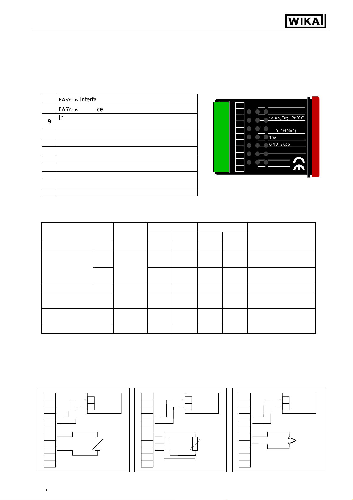
3.1. Terminal assignment
11
EASY
BUS
-Interface
10
EASY
BUS
-Interface
Input: 0 ... 1V, 0 ... 2V, 0…20mA, 4…20mA,
9
frequency, Pt100, Pt1000
8
Input: 0 ... 50mV, thermocouples, Pt100
7
Input: GND, Pt100, Pt1000
6
Input: 0 ... 10V
5
Supply voltage: GND
4
Supply voltage: +U v
3
Switching output: GND
2
Switching output: 2
1
Switching output: 1
11
10
98765 3214
11
EASYBUS
10
EASYBUS
9
1V, mA, Freq., Pt100(0)
8
mV, TC, Pt100
7
GND, Pt100(0)
6
10V
5
GND, Supply -Uv
4
Supply +Uv
3
GND
2
Output 2
1
Output 1
Hint: The contacts 3, 5 and 7 are connected internally.
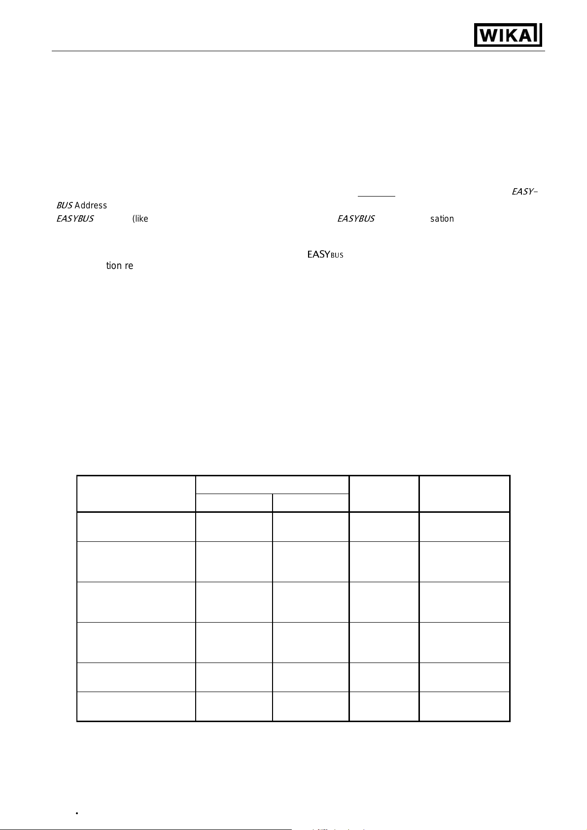
3.2. Connection data
Between
terminals
Supply voltage 4 and 5 9 V 28 V 0 V 30 V
NPN
Switching output
1 and 2
1 and 3,
2 and 3
PNP
Input mA
Input 0-1(2)V, Freq., ... 0 V 3.3 V -1 V
9 and 7
Input 0 ... 50mV, TC, ... 8 and 7 0 V 3.3 V -1 V
Input 0 ... 10V 6 and 7 0 V 10 V -1 V 20 V
These limits must not be exceeded !
typical limitations
min. max. min. max.
30V,
I<1A
I<200mA
0 mA 20 mA 0 mA 30 mA
30 V,
I<10mA
10 V,
I<10mA
notes
Not short circuit protected
Not short circuit protected
3.3. Connecting an input signal
Please take care not to exceed the limitations of the inputs when connecting the device as this may lead
to destruction of the device:
3.3.1. Connecting a Pt100 or Pt1000 or a thermocouple
Supply
+
_
9-28 VDC
4
5
7
9
Pt1000-RTD (2-wire) Pt100-RTD (3-wire) Thermocouple
V1.3
02/2011
Pt1000
4
5
7
8
9
+
_
Supply
9-28 VDC
Pt100
4
5
7
8
+
_
9-28 VDC
-
+
Supply
TC
Page 6

Operating Instructions Digital Indicator DI15
•
- 6 -
3.3.2. Connecting a 4 ... 20mA transmitter in 2-wire-technology
Supply
+
_
9-28 VDC
4
5
4-20mA
+Uv
Transmitter
7
9
-Uv
+
_
for Transmitte r
Supply
4
5
9
+
_
9-28 VDC
+Uv
Transmitter
-Uv
Supply
4-20mA
with individual transmitter supply without individual transmitter supply
3.3.3. Connecting a 0(4) ... 20mA transmitter in 3-wire-technology
Supply
+
_
9-28 VDC
4
5
7
9
+Uv
0(4)-20mA
Sig.
Transmitter
-Uv
+
_
for Transmitte r
Supply:
4
5
9
+
_
9-28 VDC
+Uv
0(4)-20mA
Sig.
Transmitter
-Uv
Supply
with individual transmitter supply without individual transmitter supply
3.3.4. Connecting a 0 ... 1V, 0 ... 2V or 0 ... 10V transmitter in 3-wire-technology
Supply
+
_
9-28 VDC
4
5
10V
6
7
1V / 2V
9
+Uv
Sig.
Transmitter
-Uv
+
_
for Transmitte r
Supply
4
5
10V
6
1V / 2V
9
with individual transmitter supply without individual transmitter supply
+
_
9-28 VDC
+Uv
Sig.
Transmitter
-Uv
Supply
3.3.5. Connecting a 0 ... 1/2/10V or 0 ... 50mV transmitter in 4-wire-technology
Supply
+
_
9-28 VDC
4
5
10V
6
7
50mV
8
1V / 2V
9
+Uv
Sig+
Transmitter
Sig-
-Uv
+
_
for Transmitte r
Supply
4
5
10V
6
7
50mV
1V / 2V
9
+
_
9-28 VDC
+Uv
Sig+
Transmitter
Sig-
-Uv
Supply
with individual transmitter supply without individual transmitter supply
V1.3
02/2011
(Note: Sig- and –Uv of the Transmitter must be the same potential)
Page 7
Operating Instructions Digital Indicator DI15
•
- 7 -
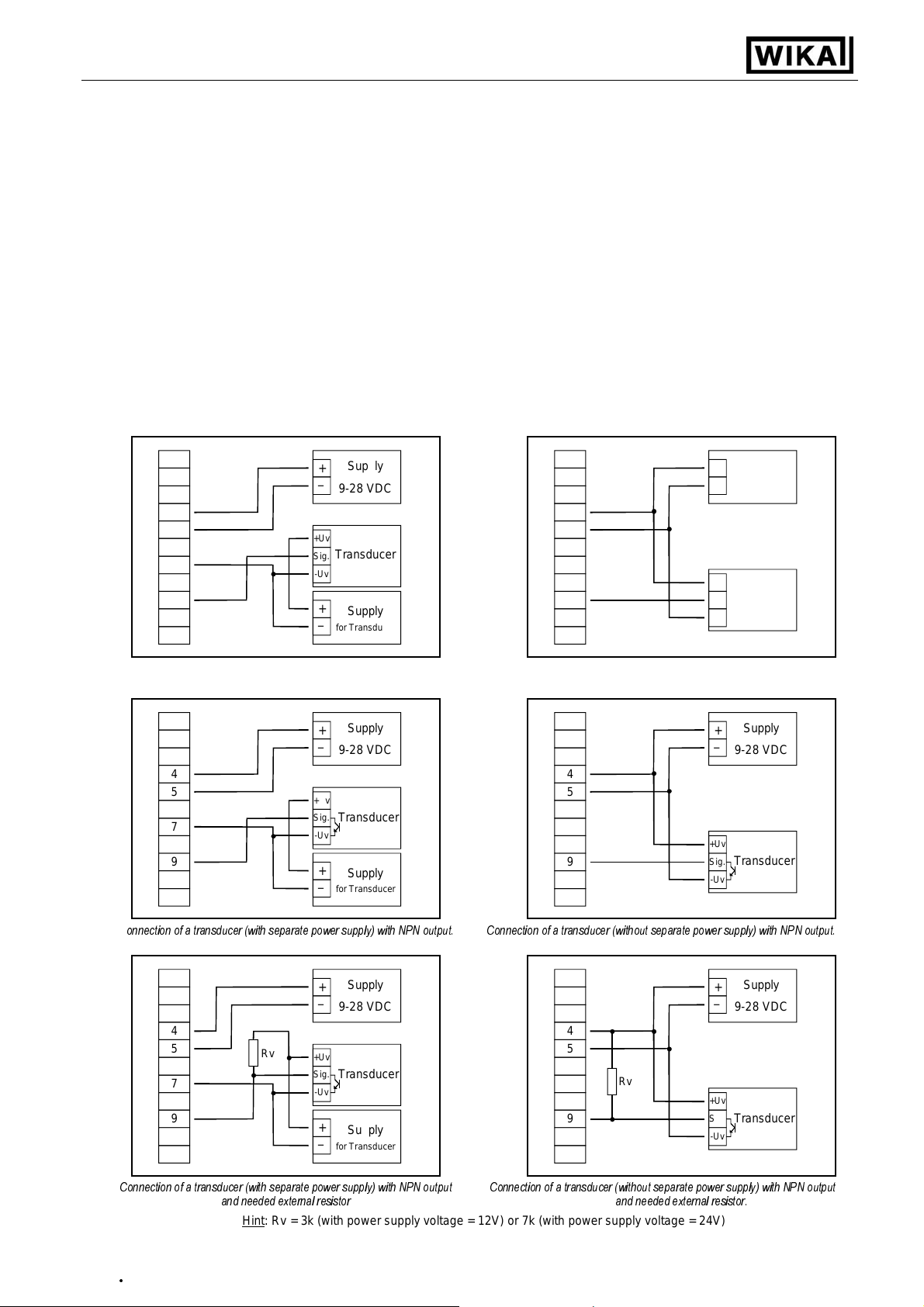
3.3.6. Connecting a frequency- or rotation-signal
When measuring frequency or rotation three different input signals can be selected in the device’s configuration.
There is the possibility of connecting an active signal (= TTL, ...), a passive sensor-signal with NPN
(= NPN-output, push-button, relay, ...) or PNP (= a PNP output switching to +Ub, high-side push-button, ...).
When configuring the device with a NPN switching output, a pull-up-resistor (~11k referring to +3.3V) is
connected internally. So when you use a device with NPN output you don‘t need to connect a resistor
externally.
When configuring the device with a PNP switching output, a pull-down resistor (~11k referring to GND)
is connected internally. So when you use a device with PNP output you don‘t need a resistor externally.
It may be that your measuring-signal source needs the connection of an external resistor e.g. the pull-upvoltage of 3.3V is not enough for the signal source, or you want to measure in the top level frequency
range. In this case the input signal has to be treated like an active signal and you have to configure the device as „TTL“.
Hint: when connecting the device you have to take care not to exceed the limits of the input
voltage respective the input current of the frequency-input.
Supply
+
_
9-28 VDC
4
5
7
9
+Uv
Transducer
Sig.
-Uv
+
_
for Transducer
Supply
4
5
9
+
_
9-28 VDC
+Uv
Transducer
Sig.
-Uv
Supply
Connection of a transducer (with separate power supply) Connection of a transducer (without separate power supply)
with TTL or PNP output and external resistor for current limitation. with TTL or PNP output and external resistor for current limitation.
Supply
+
_
9-28 VDC
4
5
7
9
+Uv
Sig.
-Uv
+
_
for Transducer
Transducer
Supply
4
5
9
+Uv
Sig.
-Uv
+
_
Supply
9-28 VDC
Transducer
C
onnection of a transducer (with separate power supply) with NPN output. Connection of a transducer (without separate power supply) with NPN output.
Supply
+
_
9-28 VDC
4
5
7
9
Connection of a transducer (with separate power supply) with NPN output
Hint
V1.3
02/2011
Rv
and needed external resistor
+Uv
Sig.
-Uv
+
_
for Transducer
Transducer
Supply
Connection of a transducer (without separate power supply) with NPN output
: Rv = 3k (with power supply voltage = 12V) or 7k (with power supply voltage = 24V)
4
5
Rv
9
and needed external resistor.
+Uv
Sig.
-Uv
+
_
Supply
9-28 VDC
Transducer
Page 8

Operating Instructions Digital Indicator DI15
•
- 8 -
Supply
+
_
9-28 VDC
4
5
7
Rv2
9
Connecting of a transducer (with individual power supply) Connecting of a transducer (without individual power supply)
PNP output with external resistor wiring. PNP output and external resistor wiring.
Hint
(Rv1 is a current limiting resistor and may be shorted if necessary. It should never exceed the mentioned value.)
: Rv2 = 600r, Rv 1 = 1k8 (with power supply voltage = 12V) or 4k2 (with power supply voltage = 24V), device config.: Sens = TTL
Rv1
+Uv
Sig.
-Uv
+
_
for Transducer
Transducer
Supply
4
5
7
9
Rv2
Rv1
+Uv
Sig.
-Uv
+
_
Netzte il:
9-28 VDC
Geber
3.3.7. Connecting a counter signal
When configuring the device you can select 3 different input signal modes similar to the connection of
frequency- and rotation-signals. The connection of a sensor-signal for a counter-signal is the same used
for the frequency- and rotation-signal.
Please use the wiring diagram given below.
There is the possibility to reset the counter. When connecting contact 8 with GND (e.g. contact 7) the
counter will be reset. You can do this manually (e.g. with the help of a push-button) or automatically
(with one switching output of the device).
Hint: When connecting the device, take care not to exceed the limits of the input-voltage or the input-
current of the frequency input.
Supply:
+
_
9-28 VDC
4
5
7
8
9
manually reset the device with the help of a push-button
2
4
5
7
8
9
automatically resetting with the help of output 2 and
additional resetting the device via push-button
Hint
: Output 2 has to be configured as NPN output
ResetButton
ResetButton
+Uv
Transducer
Sig.
-Uv
+
_
9-28 VDC
+Uv
Transducer
Sig.
-Uv
Supply
+Uv
Sig.
-Uv
+
_
Device
No.1
Device
No.2
Hint for DI15:
Device 1 – Input signal like impuls-transmitter,
Output 2 configured as NPN output
Device 2 – Input-signal = switching-contact
2
4
5
7
8
9
2
4
5
7
8
9
Cascading of DI15`s
Supply
9-28 VDC
Pulse
generator
V1.3
02/2011
Page 9
Operating Instructions Digital Indicator DI15
•
- 9 -
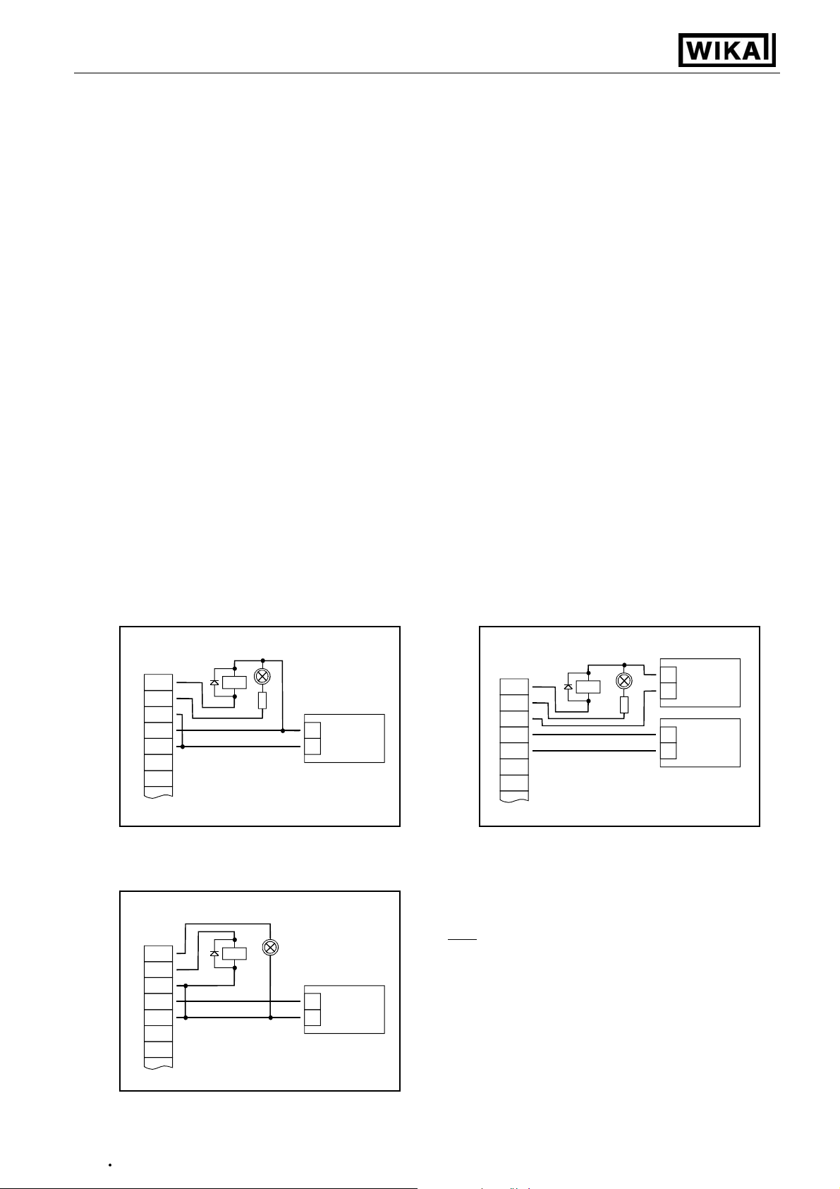
3.4. Connecting switching outputs
The device features two switching outputs, with three different operating modes for each switching output, which are:
Low-Side: “GND-switching“ NPN output (open-collector)
The switching output is connected to the negative rail of the supply voltage (connection 3
or 5) when active (switching output on).
High-Side: “+Ub-switching“ PNP output (open-collector)
The switching output is connected to the positive rail of the supply voltage (connection 4)
when active (switching output on).
Push-Pull: The switching output is connected to the negative rail of the supply voltage (connection 3
or 5) when inactive. When the switching output is active, it’s connected to the positive rail
of the supply voltage (connection 4).
In case of configuring one output as an alarm output, the output will be active in idle state (no alarm present). The output transistor switches or the push-pull output changes from +Uv to –Uv when an alarm
condition occurred.
Hint: In order to avoid unwanted or wrong switching processes, we suggest to connect the
device’s switching outputs after you have configured the device’s switching outputs
properly.
Please take care that you must not exceed the limits of the vo ltage and of the maximum current
of the switching outputs (not even for a short period of time). Please take extreme care when
switching inductive loads (like coils or relays, etc.) because of their high voltage peaks, protective measures to limit these peaks have to be taken.
When switching larg e ca pacitive loads a se ries resist or for curren t limit atio n needed , bec ause of
the high turn-on-current of high capacitive loads. The same applies to incandescent lamps,
whose turn-on-current is also quite high due to their low cold resistance.
3.4.1. Connection with configured low-side-switching output
+
1
2
3
4
5
Connection of consumer loads (relay and lamp) Connection of consumer loads (relay and lamp)
(without individual supply voltage) (with individual supply voltage)
3.4.2.
Connection with configured high-side-switching output
1
2
3
4
5
Relay
Relay
-
Supply
+
_
9-28 VDC
+
-
Supply
+
_
9-28 VDC
Hints:
Connections 3 and 5 are internally electrically connected.
When switching higher currents (> 50 mA) , the –Uv connec-
tion should not be attatched to the device (connection 3) but to
the –Uv connection of the external power supply unit.
When doing this, you get rid off ground displacement.
(NPN output, switching to GND)
+
1
2
3
4
5
Relay
-
+
_
+
_
Supply
for load
Supply
9-28 VDC
(PNP output, switching to +Uv)
Connection of consumer loads (relay and lamp)
V1.3
02/2011
Page 10

Operating Instructions Digital Indicator DI15
•
- 10 -
3.4.3. Connection with configured push-pull-switching output
+
Semicond.-
1
2
3
4
5
Connection of a semiconductor-relay
Uin
relay
-
Supply
+
_
9-28 VDC
3.5. Common wiring of several DI15
Inputs and outputs ar e not elec tricall y isolate d. W hen interconnec ting se veral DI 15`s you have to m ak e sure
that there is no potential displacement.
Make sure to observe the following points:
- When several DI15`s are connected to the s ame power suppl y unit it is highl y recomm ended to isolate the
sensors, measuring transducers etc.
- When the sensors, m easuring transduc ers etc. are elec tricall y connected, and you ca n’t manage to is olate
them, you should use separate electrically isolated power supply units for each device. Please note, that an
electric connection may also be created via the m ediu m to be m eas ured ( e.g. pH-elec tr od es and cond uc ti vity-electrodes in fluids).
V1.3
02/2011
Page 11
Operating Instructions Digital Indicator DI15
•
- 11 -
4. Configuration of the device
Please note: When you are configuring the device and don’t press any button for more than 60 sec. the
configuration of the device will be cancelled. The changes you made will not
Hint: The buttons 2 and 3 are featured with a ‘roll-function‘. When pressing the button once the value will be raised
(button 2) by one or lowered (button 3) by one. When holding the button pressed for longer than 1 sec. the
value starts counting up or down, the counting speed will be raised after a short period of time.
The device also features a ‘overflow-function‘, when reaching the upper limit of the range, the device switches
to the lower limit, vice versa.
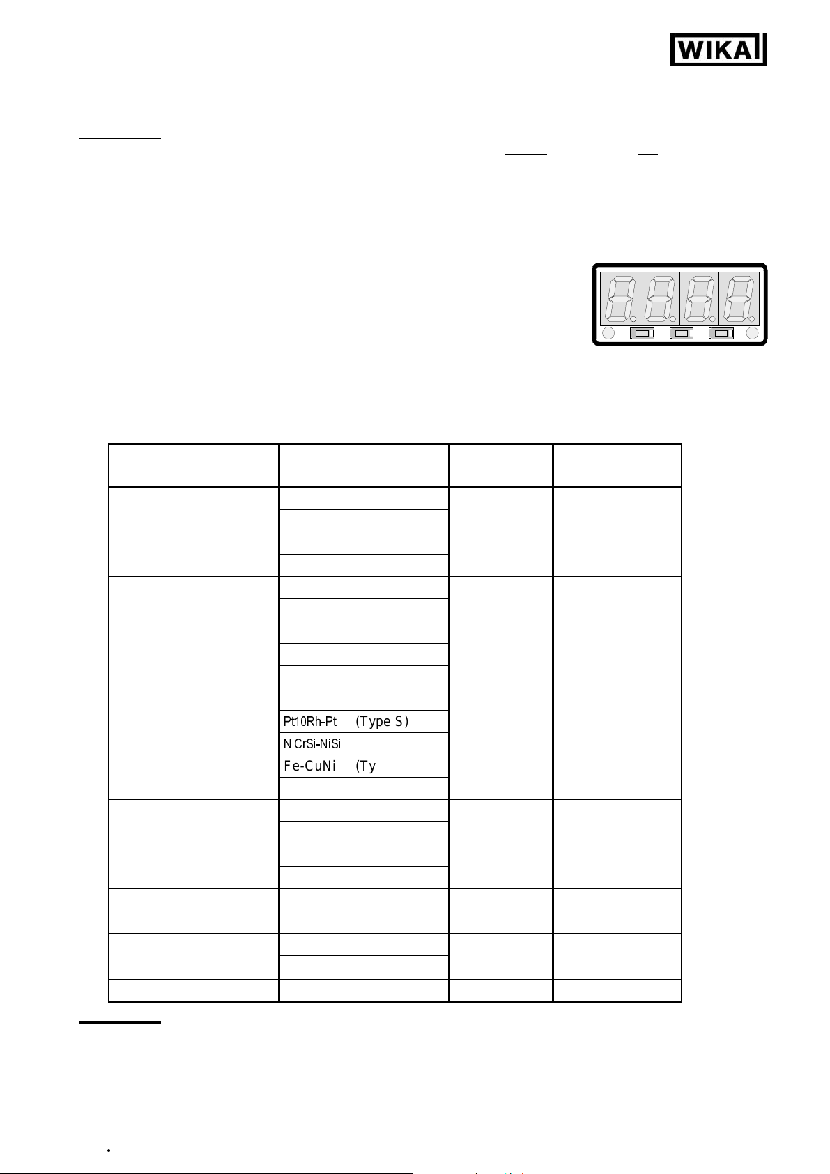
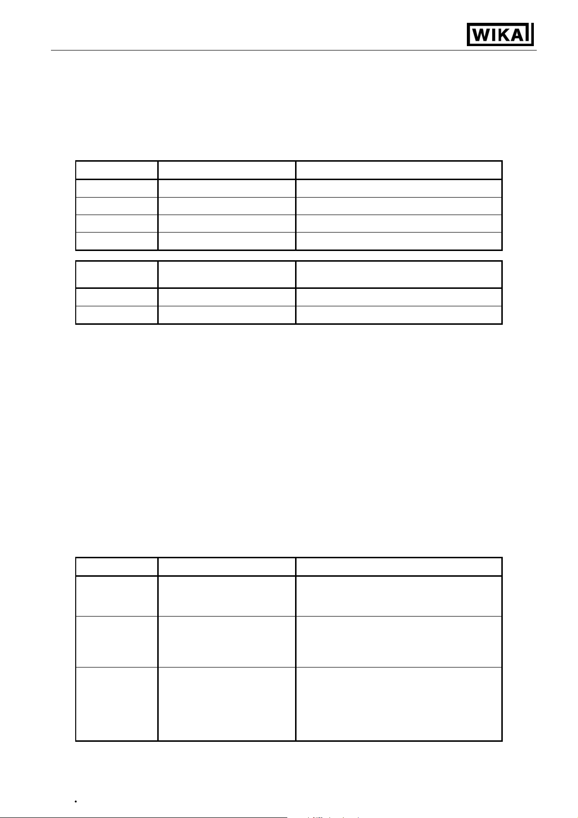
4.1. Selecting an input signal type
- Turn the device on and wait until it completed its built-in segment test.
- Press button 2 for >2 sec. (e.g. with a small screw driver)
The device displays “InP“ ('INPUT').
- Use button 2 or button 3 (middle resp. right button) to select the input signal (see table below).
- Validate the selection with button 1 (the left button). The display will show “InP“ again.
Depending on the selected input signal, additional configurations will be needed.
be saved and will be lost!
Button 1 Button 2 Button 3
Input type Signal
to select as
input
proceed in chapter
Voltage signal 0 ... 10 V
0 ... 2 V
U
4.2
0 ... 1 V
0 ... 50 mV
Current signal 4 ... 20 mA
I
4.2
0 ... 20 mA
RTD Pt100 (0.1°C)
Pt100 (1°C)
t.rES
4.3
Pt1000
Thermocouples NiCr-Ni (Type K)
Pt10Rh-Pt
NiCrSi-NiSi
(Type S)
(Type N)
t.tc
4.3
Fe-CuNi (Type J)
Cu-CuNi (Type T)
Frequency TTL-signal
FrEq
4.4
Switch-contact NPN, PNP
Rotation TTL-signal
rPn
4.5
Switch-contact NPN, PNP
Counter up TTL-signal
Co.uP
4.6
Switch-contact NPN, PNP
Counter down TTL-signal
Co.dn
4.6
Switch-contact NPN, PNP
Interface mode Serial interface
SEri
4.7
Please note: When changing the measuring mode “InP“, the input signal “SEnS“ and the display-
unit “Unit“ all settings will be changed to factory default. You have to set all the
other settings. This also regards the settings for offset and slope-adjustment as well
as the switching points!
V1.3
02/2011
Page 12
Operating Instructions Digital Indicator DI15
•
- 12 -
4.2. Measuring voltage and current (0 ... 50mV, 0 ... 1V, 0 ... 2V, 0 ... 10V, 0 ...20mA, 4 ... 20mA)
This chapter describes how you configure the DI15 for measuring voltage- resp. current-signals from an external transmitter. This instruction requires that you selected “U“ or “I“ as your desired input type like it is
explained in chapter 4.1. The display has to show “InP“.
- Press Button 1. The display shows “SEnS“.
- Select the desired input signal using button 2 or button 3 (middle resp. right button).
Display Input Signal
10.00
2.00
1.00
0.050
Display
4-20
0-20
(voltage measuring)
0 ... 10 V
0 ... 2 V
0 ... 1 V
0 ... 50 mV
Input signal
(current measuring)
4 ... 20 mA
0 ... 20 mA
Notes
Notes
- Validate the selected input signal by pressing button 1. The display shows “SEnS“ again.
- Press button 1 again, The display will show “dP“ (decimal point).
- Select the desired decimal point place by pressing button 2 resp. button 3.
- Validate the selected decimal position by pressing button 1. The display shows “dP“ again.
- Press button 1 again, the display will show “di.Lo“ (Display Low = low display value).
- Use button 2 resp. button 3 to select the desired value the device should display when a 0mA, 4mA
resp. 0V input signal is attached.
- Validate the selected value by pressing button 1. The display shows “di.Lo“ again.
- Press button 1 again, the display will show “di.Hi“ (Display High = high display value).
- Use button 2 resp button 4 to select the desired value the device should display when a 20mA, 50mV,
1V, 2V resp. 10V input signal is attached.
- Validate the selected value by pressing button 1. The display shows “di.Hi“ again.
- Press button 1 again. The display will show “Li“ (Limit = Measuring range limit).
- Use button 2 resp. button 3 to select the desired measuring range limit..
Display Measuring range limit Notes
Exceeding of the measuring range limit is
Off
Deactivated
tolerable for about 10% of the selected input
signal.
The measuring range limit is exactly bounded
on.Er
Active,
(displays error)
by the input signal. When exceeding or shortfalling the input signal the device will display
an error message.
The measuring range limit is exactly bounded
by the input signal. When exceeding or short-
on.rG
Active,
(displays the selected limit)
falling the input signal the device will display
the selected lower/upper display value.
[e.g. humidity: when shortfalling or exceeding,
the device will display 0% resp. 100%]
Hint: When exceeding the measuring range limit > 10% independently from the setting, the device will always
display an error message (“Err.1“ resp. “Err.2“).
- Press button 1 to validate the selection, the display shows “Li“ again.
V1.3
02/2011
Page 13
Operating Instructions Digital Indicator DI15
•
- 13 -
- When pressing button 1 again, the display will show “FiLt“ (Filter = digital filter).
- Use button 2 and button 3 to select the desired filter [in sec.].
Selectable values: 0.01 ... 2.00 sec.
Explanation: this digital filter is a digital replica of a low pass filter.
Note: when using the input signal 0 ... 50mV a filter value of at least 0.2 is recommended
- Press button 1 to validate your value, the display shows “FiLt“ again.
Now your device is adjusted to your signal source. Now the only thing left to do is to adjust the outputs of the
device.
- When pressing button 1 again, the display shows “outP“. (output)
For configuring the outputs of the DI15, please follow the instructions given in chapter 4.8.
4.3. Measuring temperature (Pt100, Pt1000 and thermocouples type J, K, N, S or T)
This chapter describes how to configure the device for temperature measuring with the help of external platinum RTD probes or thermocouple probes. This instruction requires that you selected “t.res“ or “t.tc“ as your
desired input type like it is explained in chapter 4.1. The device has to display “InP“.
- When pressing button 1 the display shows “SEnS“.
- Use button 2 or button 3 (middle resp. right button) to select your desired input signal.
Display
Pt0.1
Pt1
1000
Display
NiCr
S
n
J
T
Input signal
(RTD)
Pt100 (3-wire)
Pt100 (3-wire)
Pt1000 (2-wire)
Input signal
(Thermocouples)
Notes
Meas.-range: -50.0 ... +200.0 °C (-58.0...+ 392.0 °F)
Resolution: 0.1°
Meas.-range: -200 ... + 850 °C (-328 ... + 1562 °F)
Resolution: 1°
Meas.-range: -200 ... + 850 °C (-328 ... + 1562 °F)
Resolution: 1°
Notes
NiCr-Ni (type K) Meas.-range: -270 ... +1350 °C (-454 ... + 2462 °F)
Pt10Rh-Pt (type S) Meas.-range: -50 ... +1750 °C (- 58 ... + 3182 °F)
NiCrSi-NiSi (type N) Meas.-range: -270 ... +1300 °C (-454 ... + 2372 °F)
Fe-CuNi (type J) Meas.-range: -170 ... + 950 °C (-274 ... + 1742 °F)
Cu-CuNi (type T) Meas.-range: -270 ... + 400 °C (-454 ... + 752 °F)
- Validate the selected input signal by pressing button 1. The display shows “SEnS“ again.
- When pressing button 1 again, the display will show “Unit“ (the unit you want to display).
- Use button 2 and button 3 to select weather you want to display °C or °F.
- Use button 1 to validate the selected unit, the display shows “Unit“ again.
- Press button 1 to again, the display will be showing “FiLt“ (Filter = digital filter).
- Use button 2 and button 3 for setting the desired filter-value [in sec.].
Selectable values: 0.01 ... 2.00 sec.
Explanation: this digital filter is a digital replica of a low pass filter.
- Use button 1 to validate your selection, the display shows “FiLt“ again.
Now your device is adjusted to your signal source. Now the only thing left to do is to adjust the outputs of the
device.
V1.3
02/2011
Page 14

Operating Instructions Digital Indicator DI15
•
- 14 -
- When pressing button 1 again, the display shows “outP“. (output)
For configuring the outputs of the DI15, please follow the instructions shown in chapter 4.8.
For setting the offset and for setting the slope-adjustment, please follow the instructions given in chapter 6.
4.4. Measuring of frequency (TTL, switching-contact)
This chapter describes how to configure the device for measuring frequency.
This instruction requires that you selected “FrEq“ as your desired input type like it is explained in chapter 4.1.
The device has to display “InP“.
- When pressing button 1 the display will show “SEnS“.
- Use button 2 or button 3 (middle resp. right button) to select the desired input signal.
Display Input signal Note
ttL
TTL-signal
For direct connection of a passive switching
contact (e.g. push button, relay) resp. Trans-
nPn
Switching contact, NPN
mitter with NPN output.
A pull-up-resistor is internally connected.
Hint: when using push-buttons or relays, they must
be bounce-free!
For direct connection of a transmitter with
PnP
Switching contact, PNP
PNP output.
A pull-down-resistor is internally connected.
Hint: For the connection of a frequency-transmitter, please follow the instructions given in chapter 3.3.6
When connecting a switching-contact-transmitter with increased frequency range (= with external circuitry)
you have to select TTL as your desired input signal.
- Validate your selected input signal by pressing button 1. The display shows “SEnS“ again.
- When pressing button 1 again, the display will show “Fr.Lo“ (frequency low = lower frequency range
limit).
- Use button 2 and button 3 to select the lowest frequency that may occur when measuring.
- Press button 1 to validate your selection. The display shows “Fr.Lo“ again.
- When pressing button 1 again, the display will show “Fr.Hi“ (frequency high = upper frequency range limit).
- Use button 2 and button 3 to select the highest frequency that may occur when measuring.
- Press button 1 to validate your selection. The display shows “Fr.Hi“ again.
- When pressing button 1 again, the display will show “dP“ (decimal point).
- Use button 2 and button 3 to select the desired decimal point position.
- Press button 1 to validate your selection. The display shows “dP“ again.
- When pressing button 1 again, the display will show “di.Lo“ (display low
=
display at lower frequency range
limit).
- Set the value the device shall display at the lower frequency range limit by pressing button 2 resp.
button 3.
- Press button 1 to validate your selection. The display shows “di.Lo“ again.
- When pressing button 1 again, the display will show “di.Hi“ (display high = display at upper frequency range
limit).
- Set the value the device shall display at the upper frequency range limit by pressing button 2 resp.
button 3.
- Press button 1 to validate your selection. The display shows “di.Hi“ again.
- When pressing button 1 again, the display will show “Li“ (limit = measuring range limitation).
- Use button 2 and button 3 to select the desired measuring range limitation.
V1.3
02/2011
Page 15
Operating Instructions Digital Indicator DI15
•
- 15 -
Display Measuring range limit Note
Exceeding of the measuring-frequency is tol-
off
on.Er
on.rG
Hint: When exceeding the maximum range limit (10kHz) independently from the limit setting an error message
will be displayed (“Err.1“).
(frequency range limit)
- Press button 1 to validate your selection. The display shows “Li“ again.
- When pressing button 1 again, the display will show “FiLt“ (Filter = digital filter).
Inactive
active,
(error indicator)
active,
erable until you reach the maximum measuring range limit.
The measuring range is exactly bounded by
the selected frequency-measuring-range-limit.
When exceeding or shortfalling of the limit the
device will display an error mess age.
The measuring range is exactly bounded by
the selected frequency-measuring-range-limit.
When exceeding or shortfalling of the limit the
device will display the lower or upper displayrange-limit. [e.g. for humidity: when shortfal-
ling resp. exceeding the device will display 0%
resp. 100%]
- Use button 2 and button 3 to select the desired filter value [in sec.].
Usable values: 0.01 ... 2.00 sec.
Explanation: this digital filter is a digital replica of a low pass filter.
- Press button 1 to validate your selection. The display shows “FiLt“ again.
Now your device is adjusted to your signal source. The only thing you left do is to adjust the outputs of the
device.
- When pressing button 1 again, the display will show “outP“. (Output)
For configuring the outputs of the DI15, please follow the instructions shown in chapter 4.8.
4.5. Measuring of rotation speed (TTL, switching-contact)
This chapter describes how to configure the device for measuring rotation speed.
This instruction requires that you selected “rPn“ as your desired input type like it is explained in chapter 4.1. The
device has to display “InP“.
- When pressing button 1 the device will display “SEnS“.
- Use button 2 or button 3 (middle resp. right button) to select the desired input signal.
Display Input-signal Notes
ttL
nPn
TTL-signal
Switching contact, NPN
For direct connection of a passive switching
contact (e.g. push button, relay) resp. transmitter with NPN output.
A pull-up-resistor is internally connected.
Hint: when using push-buttons or relays, they must
be bounce-free!
For direct connection of a transmitter with
PnP
Switching contact, PNP
PNP output.
A pull-down-resistor is internally connected.
Hint: For the connection of a frequency-transmitter, please follow the instructions given in chapter 3.3.6
When connecting a switching-contact-transmitter with increased frequency range (= with external circuitry)
you have to select TTL as your desired input signal.
- Press button 1 to validate your selected input signal. The display shows “SEnS“ again.
- When pressing button 1 again, the display will show “diu“ (divisor).
V1.3
02/2011
Page 16

Operating Instructions Digital Indicator DI15
•
- 16 -
- Use button 2 and 3 to select your desired divisor.
Set the divisor to the pulses per rotation the transmitter supplies.
- Press button 1 to validate your selection. The display shows “diu“ again.
- When pressing button 1 again, the display will show “dP“ (decimal point).
- Use button 2 and button 3 to select the desired decimal point position.
Use the decimal point p osition to change the resolution of yo ur measurement. The more the decimal
point position is on the left, the finer the resolution will become. Please note that you lower the maximum
value that can be displayed, too.
Example
With no decimal po int the devic e will display something lik e 49 – 50 – 5 1, the maximum v alue that can
be displayed is 9999 rotations per minute.
With the decimal point position on the left e.g. XX.XX the device will display something like 49.99 –
50.00 – 50.01, but the maximum value that can be displayed is 99.99 rotations per minute.
- Press button 1 to validate your selection. The display shows “dP“ again.
Now your device is adjusted to your signal source. The only thing left to do is to adjust the outputs of the
device.
- When pressing button 1 again, the display will show “outP“. (Output)
For configuring the outputs of the DI15, please follow the instructions shown in chapter 4.8.
: your engine runs with 50 rotations per minute.
4.6. Up-/Downwards counter (TTL, switching-contact)
The upwards counter starts counting up from 0, according to adjusted limit.
The downwards counter starts counting downwards from the upper value that was been selected.
Feature: T he current value of the counter can be res et anytime by connecting pin 8 to GND (e.g. pin 7).
The counter starts from its beginning as you disconnect pin 8 and pin 7.
T he current counter value won‘t be los t if the voltage supply is disconn ected. After restarting, the
counter starts from this value.
This chapter describes how to configure the device as a counter.
This instruction requires that you selected “Co.up“ or “Co.dn“ as your desired input type like it is explained in
chapter 4.1.The device has to display “InP“.
- When pressing button 1 the display will show “SEnS“.
- Use button 2 or button 3 (middle resp. right button) to select the desired input signal.
Display Input-signal Note
ttL
nPn
TTL-signal
Switching contact, NPN
For direct connection of a passive switching
contact (e.g. push button, relay) resp. transmitter with NPN output.
A pull-up-resistor is internally connected.
Hint: when using push-buttons or relays, they must
be bounce-free!
For direct connection of a transmitter with
PnP
Switching contact, PNP
PNP output.
A pull-down-resistor is internally connected.
Hint: For connecting a frequency-transmitter, please follow the instructions given in chapter 3.3.7
When connecting a switching-contact-transmitter with increased frequency range (= with external circuit)
you have to select TTL as your desired input signal.
- Press button 1 to validate your selected input signal. The display shows “SenS“ again.
- When pressing button 1 again, the device will be displaying “EdGE“ (signal edge).
V1.3
02/2011
Page 17
Operating Instructions Digital Indicator DI15
•
- 17 -
- Use button 2 or button3 (middle resp. right button) to select the desired signal edge.
Display Signal edge Note
PoS
nEG
Positive
Negative
The counter is triggered on the positive (rising) edge.
The counter is triggered on the negative (falling) edge.
- Press button 1 to validate your selection, the display shows “EdGE“ again.
- When pressing button 1 again, the display will show “diu“ (divisor = pre-scaling factor).
- Use button 2 and button 3 to select the desired pre-scaling factor.
The incoming pulses will be divided with the selected pre-scaling factor, after that they will be transmitted to the device for further processing.
By this factor you can adapt the device to your transmitter or select a pre-scaling factor for large values
Example 1
165th pulse (so 1 pulse per litre) will be used for further processing.
Example 2
of the DI15. But when setting a pre-scaling factor of 1000 only every 1000th pulse is used for further processing. So
you only got a value 5000 which won’t exceed the limit of the DI15
: Your flow rate transmitter supplies 165 pulses per litre. When setting a pre-scaling factor of 165, every
: Your transmitter is supplying about 5 000 000 pulses during the measurement, which exceeds the limit
.
- Press button 1 to validate your selection. The display shows “diu“ again.
- Press button 1 again. The display shows “Co.Hi“ (counter high
=
upper counting range limit).
- Use button 2 and button 3 to select the maximum pulse-count (after pre-scaling factor) for the counting
process.
Example: Your flow rate transmitter is supplying 1800 pulses per litre, you selected a pre-scaling factor of 100 and
you are expecting a maximum flow rate of 300 litres during the measurement. With a pre-scaling factor of 100 selected, you will get 18 pulses per litre. With a maximum flow rate of 300 litres you will be getting a pulse count of 18
* 300 = 5400.
- Press button 1 to validate your selection. The display shows “Co.Hi“ again.
- When pressing button 1 again, the device will be displaying “dP“ (decimal point).
- Use button 2 and button 3 to select the desired decimal point position.
- Press button 1 to validate your selected decimal point position. The display shows “dP“ again.
=
- Press button 1 again. The display shows “di.Hi“ (display high
upper display range limit).
- Use button 2 and button 3 to set the value to be displayed when the maximum pulse (setting of co.Hi)
count is reached.
Example: Your flow rate transmitter is supplying 1800 pulses per litre and you are expecting a maximum flow rate of
300 litres. You selected a pre-scaling factor of 100 and a counter range limit of 5400. When wanting a resolution of
0.1 litres shown in the display of the device you would have to set the decimal point position to ---.- and a display
range limit of 300.0.
- Press button 1 to validate your selection. The display shows “di.Hi“ again.
- Press button 1. The display will show “Li“ (Limit
= measuring range limit
).
- Use button 2 and button 3 to select the desired measuring range limit (counter range limit).
Display Measuring range limit Note
Exceeding of the counter range is tolerable
off
Inactive
until you reach the maximum measuring
range limit.
The measuring range is exactly bounded by
on.Er
active,
(error indicator)
the selected counter-range-limit. When exceeding or shortfalling of the limit the device
will display an error message.
The measuring range is exactly bounded by
on.rG
active,
(measuring range limit)
the selected counter-range-limit. When exceeding or shortfalling of the limit the device
will display the upper counter-range-limit or 0
Hint: The lower counter-range-limit (for configured downwards counter) is fixed to 0.
V1.3
02/2011
Page 18
Operating Instructions Digital Indicator DI15
•
- 18 -
- Press button 1 to validate your selection. The display shows “Li“ again.
Now your device is adjusted to your signal source. The only thing left to do is to adjust the outputs of the
device.
- When pressing button 1 again, the display will show “outP“. (Output)
For configuring the outputs of the DI15, please follow the instructions shown in chapter 4.8.
4.7. Interface mode
When the device is in the interface mode it won’t make any measurements by itself. The value shown in the device’s display is sent via serial interface. But the switching and alarm functions of the displayed
BUS
-Address of the device needed for the communication can be set manually with the device itself or with the help of an
EASYBUS
will be reset automatically.
-software (like EbxKonfig). Please note, when carrying out an
EASYBUS
value are still available. The
-system-initialisation the device’s address
EASY-
This chapter describes how to configure the device as an
EASY
BUS
-display.
This instruction requires that you selected “SEri“ as your desired input type like it is explained in chapter 4.1
The device has to display “InP“.
- When pressing button 1 again, the device will display “Adr“ (address).
- Use button 2 and button 3 to select the desired address [0 ... 239] of the device.
- Press button 1 to validate the selected device address. The display shows “Adr“ again.
You don’t need any further configuration except the outputs.
- When pressing button 1 again, the device will be displaying “outP“ (output).
For configuring the outputs please follow the instructions given in chapter 4.8.
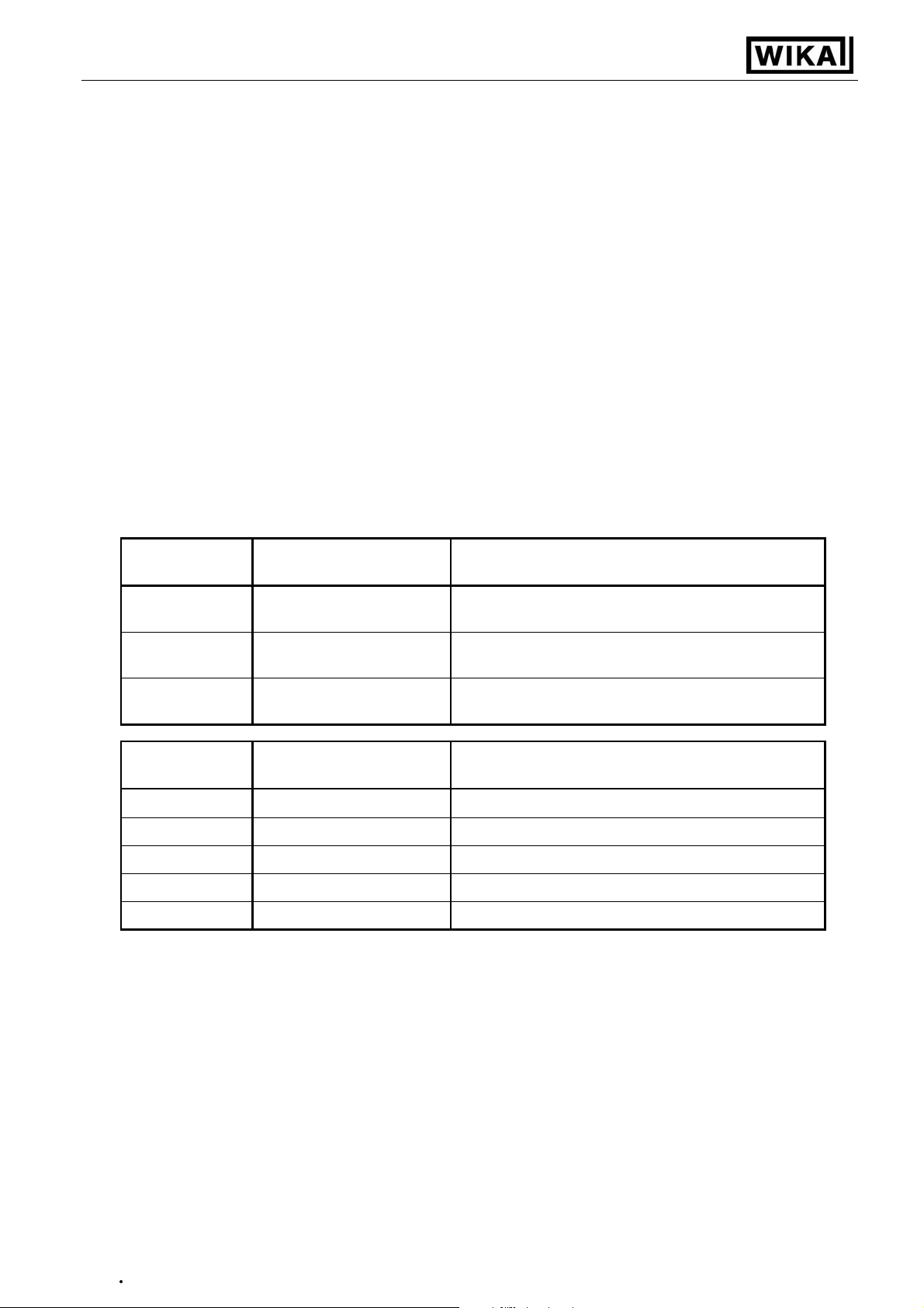
4.8. Selection of the output function
- After configuration of the input (chapter 4.2 – 4.7) you have to select the output function.
The display shows “outP“ (output).
- Use button 2 and button 3 (middle resp. right button) to select the desired output-function.
Description
No output, device is used
as display unit
Function
Output 1 Output 2
--- ---
To select as
output
no
See chapter
--
2-point-controller digital
2-point-
---
2P
5.1
controller
3-point-controller digital
2-pointcontroller
2-point-controller with
Min-/Max-alarm
digital
2-point-
digital
2-pointcontroller
Min-/Max-alarm
3P
2P.AL
5.1
5.2
controller
Min-/Max-alarm,
common
Min-/Max-alarm,
individual
--- Min-/Max-alarm
Max-alarm Min-alarm
AL.F1
AL.F2
5.3
5.3
- Press button 1 to validate the selected output function. The display shows “outP“ again.
Depending on your output function set ting, it may be possible that one or more settings describ ed below
won’t be available.
V1.3
02/2011
Page 19

Operating Instructions Digital Indicator DI15
•
- 19 -
- When pressing button 1 again, the device will display “1.dEL“ (delay of output 1).
- Use button 2 and button 3 to set the desired value [in sec.] for the switching-delay of output 1.
- Press button 1 to validate the selection. The display shows “1.dEL“ aga in.
- When pressing button 1 again, the device will display “1.out“ (type of output 1).
- Use button 2 or button 3 (middle resp. right button) to select the desired output function.
Display Kind of output Note
Low-Side
nPn
NPN, open collector,
switching GND
PnP
PNP, open collector,
switching +Ub
High-Side
Pu.Pu
Push-Pull
- Press button 1 to validate the selection. The display shows “ 1.out“ again.
- When pressing button 1 again, the device will display “1.Err“ (preferred state of output 1).
- Use button 2 and button 3 (middle resp. right button) to set the desired initial state in case of an error.
Display Preferred state of the output Note
Low-/High-side-switch is opened in case of an
off
Inactive in case of an error
error.
Push-Pull-output is low in case of an error.
Low-/High-side-switch is closed in case of an
on
Active in case of an error
error.
Push-Pull-output is high in case of an error.
- Press button 1 to validate the selection. The display shows “1.Err“ again.
- In case you selected a 3-point-controller you have to make the following settings similar to the settings
you already made for output 1:
“2.dEL“ (delay of output 2), “2.out“ (kind of output 2), “2.Err“ (preferred state of output 2).
- When pressing button 1 again, (only if you configured the device with min-/max-alarm)
the device will be displaying “A.out“ (kind of the alarm-output).
- Use button 2 or button 3 (middle resp. right button) to select the desired kind of the alarm-output.
Display Kind of the alarm-output Note
nPn
PnP
Low-Side
NPN, open collector,
switching GND
High-Side
PNP, open collector,
switching +Ub
Switching output is closed (connected to
GND) as long there is no alarm-condition, and
is opened if there is an alarm-condition.
Switching output is closed (is under voltage)
as long there is no alarm-conditi on, and is
opened if there is an alarm-condit io n.
Switching output is high with no alarm-
Pu.Pu
Push-Pull
condition and changes to low if there is an
alarm-condition.
Please Note: The switching outputs are inverted when using them as alarm-outputs!
This means as long there is no alarm-condition, the switching output will be
active! In case of an alarm-condition the output will become inactive!
Note: When using the output function “min-/max-alarm, individual “ the setting for type of alarm
output is used for both
alarm-outputs.
- Press button 1 to validate the selection. The display shows “ A.out“ again.
V1.3
02/2011
Page 20

Operating Instructions Digital Indicator DI15
•
- 20 -
Depending on the selected output function you have to make the settings for switching resp. alarm points.
See description in chapter „switchpoints resp. alarm-boundaries“ for further information.
Hint: The settings for the switching and alarm points can be made later in an extra menu (see chapter 5)
V1.3
02/2011
Page 21

Operating Instructions Digital Indicator DI15
•
- 21 -
5. Switchpoints resp. alarm-boundaries
Please note: The settings of the switchpoints wi ll b e c ancel led , whe n no button was pressed for more than
60 sec. changes you may have made already won‘t
be saved and will be lost!
Please note:
The settings of the switchpoints and alarm-boundaries will automatically be reset to factory de-
fault when any changes for the settings “InP”, “SEnS“ resp. “Unit“ had been made!
Hint: The buttons 2 and 3 are featured with a ‘roll-function‘. When pressing the button once the value will be raised
(button 2) by one or lowered (button 3) by one. When holding the button pressed for longer than 1 sec. the
value starts counting up or down, the counting speed will be raised after a short period of time.
The device also features an ‘overflow-function‘, when reaching the upper limit the device switches to the lower
limit, vice versa.
- When pressing button 1 for >2 sec. the menu to select the switchpoints and
alarm-boundaries will be called.
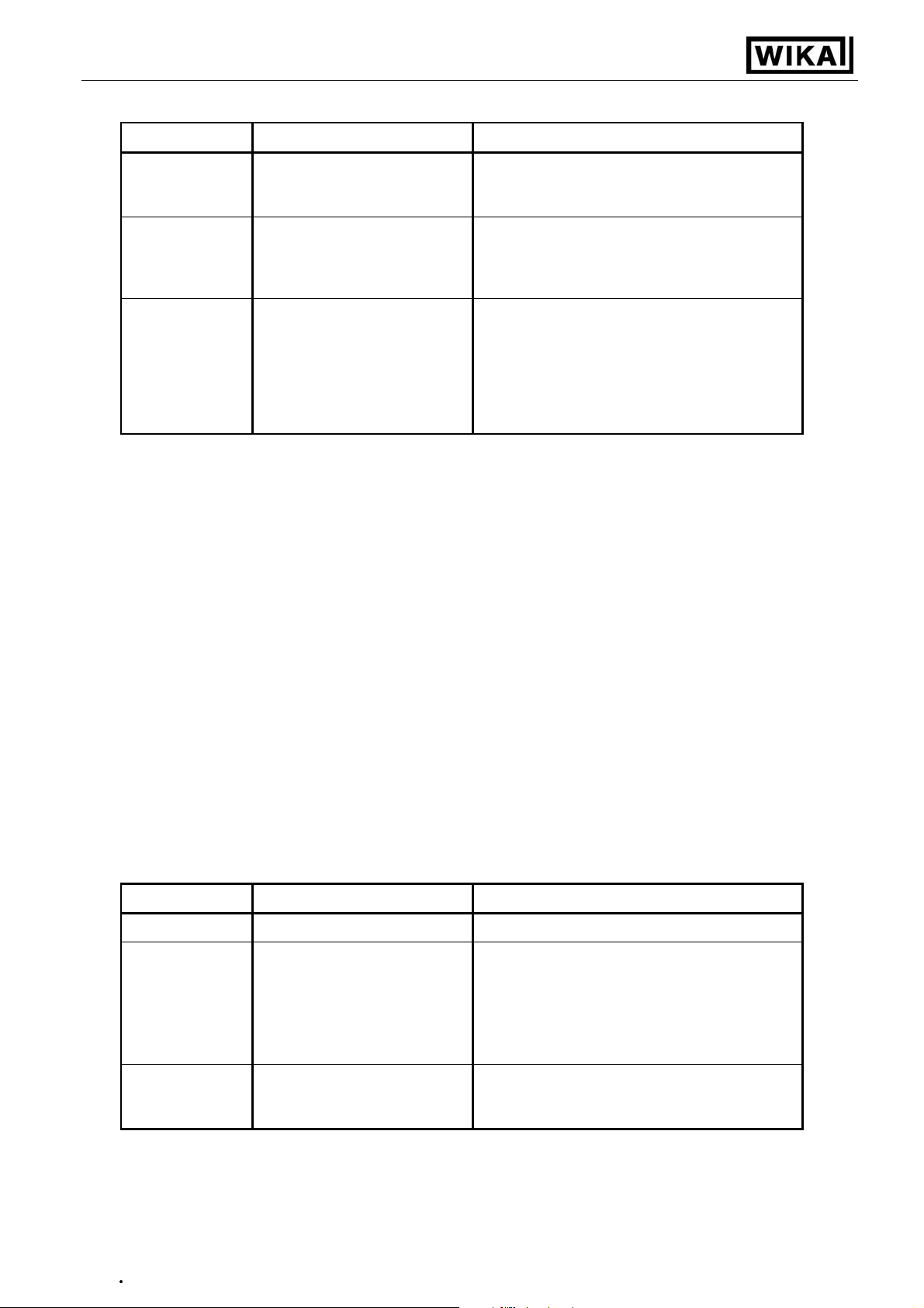
- Depending on the configuration you have made in the „output“ menu you
will get different Display values. Please follow the specific chapter for further information.
Description
Function
Output 1 Output 2
No output, device is used
as displaying unit
--- ---
2-point-controller digital
2-point-controller
3-point-controller digital
2-point-controller
--digital
2-point-controller
Selected
as output
no
2P
3P
Button 1 Button 2 Button 3
Go on in chapter
No function call
possible
5.1
5.1
2-point-controller with
min-/max-alarm
min-/max-alarm, common --- min-/max-alarm
min-/max-alarm, individ-
ual
digital
2-point-controller
min-/max-alarm
max-alarm min-alarm
2P.AL
AL.F1
AL.F2
5.2
5.3
5.3
5.1. 2-point-controller, 3-point-controller
This chapter describes how to configure the device as a 2-point-controller resp. 3-point-controller.
This instruction demands that you selected “2P“ or “3P“ as your desired output function like it is explained in
chapter 4.8.
- Press button 1
- Use button 2 and button 3 to set the desired value, the device’s output 1 should be turning on.
- Press button 1 to validate your selection. The display shows “1.on“ again.
- When pressing button 1 again, the device will be displaying “1.off“. (turn-off-point of output 1)
- Use button 2 and button 3 to set the desired value, the device’s output 1 should be turning off.
- Press button 1 to validate your selection. The display shows “1.off“again.
Example:
You want to control the temperature of a heating coil, with a hysteresis of +2°C, to 120°C.
Therefor you will have to selec t the turn- o n-po int “ 1.o n“ to 120°C an d the turn- o ff-p oint to “ 12 2°C“ .
When your heating co il temper ature falls be low 120°C it will be t urned on. W hen the te mperature
rises above 122°C the heating coil will be turned off.
Note: Depending on the inertia of your heating coil an overshooting of the temperature may be possible.
(if not already done).
The device will be displaying “1.on“ (turn-on-point of output 1).
When selected ‘2-point-controller‘ you finished configuring your device. Press button 3 to switch over to display the measuring value.
When selected ‘3-point-controller‘ please follow the instructions given below.
V1.3
02/2011
Page 22

Operating Instructions Digital Indicator DI15
•
- 22 -
- Press button 1
(if not already done).
The device will be displaying “2.on“ (turn-on-point of output 2).
- Use button 2 and button 3 to set the desired value, the device’s output 2 should be turning on.
- Press button 1 to validate your selection. The display shows “2.on“ again.
- When pressing button 1 again, the device will be displaying “2.off“. (turn-off-point of output 2)
- Use button 2 and button 3 to set the desired value, the device’s output 2 should be turning off.
- Press button 1 to validate your selection. The display shows “2.off“again.
Now you finished configuring your device. Press button 3 to switch over to display the measuring value.
5.2. 2-point-controller with alarm function
This chapter describes how to configure the device as a 2-point-controller with alarm function.
This instruction demands that you selected “2P.AL as your desired output function like it is explained in
chapter 4.8.
- Press button 1
(if not already done).
- Use button 2 and button 3 to set the desired value, the device’s output 1 should be turning on.
- Press button 1 to validate your selection. The display shows “1.on“ again.
- When pressing button 1 again, the device will be displaying “1.off“. (turn- off- point of output 1)
- Use button 2 and button 3 to set the desired value, the device’s output 1 should be turning off.
The device will be displaying “1.on“ (turn-on-point of output 1).
- Press button 1 to validate your selection. The display shows “1.off“again.
Example:
You want to control the temperature of a cooling chamber between –20°C and –22°C.
Therefor you will have to s elect –20°C for the turn-on-point 1 “1.o n“ and –22°C for the turn-offpoint 1 “1.off“. When the t emperature rises above –20°C th e device turns its output 1 on, when
falling below –22°C the device will turn its output 1 off.
Note: Depending on the inertia of your cooling circuit an overshooting of the temperature may be possible.
- When pressing button 1, the device will be displaying “AL.Hi“. (maximum alarm-value)
- Use button 2 and button 3 to set the desired value, the device should turn on its maximum-alarm.
- Press button 1 to validate your selection. The display shows “AL.Hi“ again.
- When pressing button 1 again, the device will be displaying “AL.Lo“. (minimum alarm-value)
- Use button 2 and button 3 to set the desired value, the device should turn on its minimum-alarm
- Press button 1 to validate your selection. The display shows “AL.Lo“ again.
- When pressing button 1 again, the device will be displaying “A.dEL“. (delay of the alarm-function)
- Use button 2 and button 3 to set the desired delay of the alarm-function.
Note: The unit of the value to be set is in [sec.]. The device will turn on the alarm after the
minimum resp. the maximum alarm value was active for the delay-time you have set.
- Press button 1 to validate the delay time. The display shows “A.dEL“ again.
Example:
You want to have an alarm monitoring for the cooling chamber mentioned above. The alarms
should start when the temperature will be rising above –15°C resp. falling below –30°C.
Therefor you have to selec t –15°C for the maximum alarm-v alue “Al.Hi“ and –30°C for the minimum alarm-value “AL.Lo“.
The alarm will be starting a fter the temper ature r ises a bove –15°C an d stay s abo ve –15°C for th e
entered delay time res p. after it had b een falling belo w –30°C and stay s below –30° C for the entered delay time.
Please note that the alarm-outputs are inverted! This means, that the output will be active
if there is no
alarm!
Now you finished configuring your device. Press button 3 to switch over to display the measuring value.
V1.3
02/2011
Page 23

Operating Instructions Digital Indicator DI15
•
- 23 -
monitoring.
5.3. Minimum/maximum-alarm (individual or common)
This chapter describes how to configure the device‘s alarm boundaries for min-/max-alarmThis instruction demands that you selected “AL.F1“ resp. “AL.F2“ as your desired output function like it is
explained in chapter 4.8.
- Press button 1
(if not already done)
, the device will be displaying “AL.Hi“. (maximum alarm-value)
- Use button 2 and button 3 to set the desired value, the device should turn on its maximum-alarm.
- Press button 1 to validate your selection. The display shows “AL.Hi“ again.
- When pressing button 1 again, the device will be displaying “AL.Lo“. (minimum alarm-value)
- Use button 2 and button 3 to set the desired value, the device should turn on its minimum-alarm
- Press button 1 to validate your selection. The display shows “AL.Lo“ again.
- When pressing button 1 again, the device will be displaying “A.dEL“. (delay of the alarm-function)
- Use button 2 and button 3 to set the desired delay of the alarm-function.
Note: The unit of the value to be set is in [sec.]. The device will turn on the alarm after minimum
resp. maximum alarm value was active for the delay-time you have set.
- Press button 1 to validate the delay time. The display shows “A.dEL“ again.
Example:
You want to have a temper ature alar m-monitor ing of a greenhous e. The alarm shoul d start whe n
the temperature rises above 50°C resp. falls below 15°C.
Therefore your settings will be 50°C for t he maximum alar m-value “AL.H I“ and 15°C for th e minimum alarm-value “AL.Lo“.
The alarm will start after the temp erature rises abov e 50°C and s tays above 50° C for the entered
delay time resp. after it ha d been falling below 15 °C and stays below 15°C for the entered delay
time.
Please note that the alarm-outputs are inverted! This means, that the output will be active
when there is no
alarm!
Now you finished configuring your device. Press button 3 to switch over to display the measuring value.
V1.3
02/2011
Page 24

Operating Instructions Digital Indicator DI15
•
- 24 -
6. Offset- and slope-adjustment
The offset and slope-adjustment function can be used for compensating the tolerance of the used sensor,
resp. for fine adjustment of the used transducer resp. transmitter.
Please note:
Please note:
The settings of the offset- / slope-adjustment will be cancelled, if no button was pressed for
more than 60 sec. Changes you may have made already won‘t
be saved and will be lost!
The settings of the offset- / slope-adjustment and alarm-boundaries will automatically be reset to
factory default when any changes for the settings “InP”, “SEnS“ resp. “Unit“ had been made!
Hint: The buttons 2 and 3 are featured with a ‘roll-function‘. When pressing the button once the value will be raised
(button 2) by one or lowered (button 3) by one. When holding the button pressed for longer than 1 sec. the
value starts counting up or down, the counting speed will be raised after a short period of time.
The device also features a ‘overflow-function‘, when reaching the upper limit the device switches to the lower
limit, vice versa.
- Turn on the device and wait after it finished its built-in segment test.
- Press button 3 > 2 sec. (e.g. with a small screwdriver).
The device will be displaying „OFFS“ (offset).
- Use button 2 and button 3 for setting the desired zero point offset-value.
Button 1 Button 2 Button 3
The input of the offset will be in digit resp. °C/°F.
The value that had been set will be subtracted from the measured value.
(
see below for further information
)
- Press button 1 to validate your selection. The display shows “OFFS“ again.
- When pressing button 1 again, the device will be displaying “SCAL“. (scale = slope)
- Use button 2 and button 3 to select the desired slope-adjustment.
The slope adjustment will be entered in %. The value displayed can be calculated like this:
Displayed value = (measured value – zero point offset) * (1 + slope adjustment [% / 100]).
Example: The setting is 2.00 => the slope has risen 2.00% => slope = 102%.
When measuring a value of 1000 (without slope-adjustment) the device would display 1020 (with slope adjustment of 102%)
- Press button 1 to validate the selection of the slope-adjustment. The display shows “SCAL“ again.
Examples for offset- and slope-adjustment:
Example 1: Connecting a Pt1000-sensor (with an offset error depending on the cable-length of the sensor)
The device displays the following values (without offset- or slope-adjustment): 2°C at 0°C and 102°C at 100°C
Therefore you calculated: zero point: 2
slope: 102 – 2 = 100 (
You have to set: offset = 2
scale = 0.00
Example 2:
The device displays the following values (without offset- or slope-adjustment): 0.08 at 0.00 bar and 20.02 at 20.00 bar
Therefore you calculated: zero point: 0.08
slope: 20.02 – 0.08 = 19.94
deviation: 0.06
You have to set: offset = 0.08
scale = 0.30
Example 3:
The device displays the following values (without offset- or slope-adjustment): 0.00 at 0.00 l/min and 16.17 at 16.00 l/min
Therefore you calculated: zero point: 0.00
slope: 16.17 – 0.00 = 16.17
deviation: - 0.17
You have to set: offset = 0.00
scale = - 1.05
Connecting of a 4 ... 20mA-pressure-transmitter
Connecting of a flow-rate-transducer
deviation = 0
(= zero point-deviation)
(= target-slope – actual-slope = 20.00 - 19.94)
(= zero point-deviation)
(= deviation / actual-slope = 0.06 / 19.94 = 0.0030 = 0.30% )
(= target-slope – actual slope = 16.00 - 16.17)
(= deviation / actual-slope = - 0.17 / 16.17 = - 0.0105 = - 1.05% )
)
V1.3
02/2011
Page 25

Operating Instructions Digital Indicator DI15
•
- 25 -
7. Min-/max-value storage
The device features a minimum/maximum-value storage. In this storage the highest resp. lowest performance
data is saved.
Calling of the minimum-value press button 3 shortly the device will display “Lo“ briefly, after that
the min-value is displayed for about 2 sec.
Calling of the maximum-value press button 2 shortly the device will display “Hi“ briefly, after that
the max-value is displayed for about 2 sec.
Erasing of the min/max values press button 2 and 3 for 2 sec. The device will display “CLr“ briefly, after
that the min/max-values are set to the current displayed value.
8. Serial interface
The device features one
EASY
BUS
-Interface. You can use the device as a full function
EASY
BUS
-device. The
serial interface allows the device to communicate with a host computer. Data polling and data transfer is
done in master/slave mode, so the device will only send data on demand. Every device has a unique IDnumber that makes exact identification of each device possible. With the help of a software (like DI15config –
available on request) you are able to reassign an address to the device.
Additional accessories needed for the interface mode:
EASY
BUS
- Level converter
PC: e.g. EBW1, EBW2
- Software for communication with the device
EBS9M: 9-channel-software for displaying a measured value.
EASYCONTROL: multi-channel software for real-time-recording and displaying measure-values of a de-
vice in ACCESS®-database-format.
EASYBUS-DLL: EASYBUS-developer-package for developing own software. This package features a
universal WINDOW S®-Libr ar y with documentation and program-ex am ples. The DLL
can be used in any usual programm ing langua ge.
V1.3
02/2011
Page 26

Operating Instructions Digital Indicator DI15
•
- 26 -
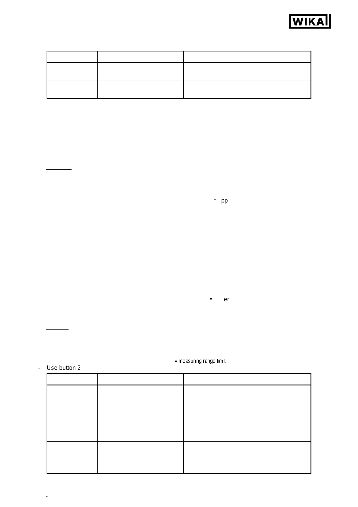
9. Error codes
When detecting an operating state which is not permissible, the device will display an error code
The following error codes are defined:
Error presumed cause Solution
Err 1
- Exceeding of the measuring - Sensor broken the limits
range - Sensor shorted - Check sensor, transducer / transmitter
- Check device configuration
- Reset the counter
Err 2
- Values below measuring - Current below 4 mA the limits
range - Sensor shorted - Check sensor, transducer/ transmitter
- Sensor broken - Check device configuration
- Counter underflow - Reset the counter
Err 3
- Display range has been - Counter overflow display value is below 9999
exceeded
Err 4
- Values below display range - Counter underflow display value is above -1999
- Defective device - Reset the counter
Err 7
- System error has been exceeded - Exchange the defective device
Err 9 - Sensor broken /shorted
- Sensor defective -Sensor broken (Thermocouple)
Err 11
- Value could not be calculated
- Input signal to high - The input sighnal must be within
- Input signal to low /negative - The input sighnal must be within
- Incorrect scale - The error message will be reset if the
- Incorrect scale - The error message will be reset if the
- Valid operation temperature - Stay within valid temperature range
(PT100)
- Check sensor
- Incorrect scale - Check settings and input signal
V1.3
02/2011
Page 27
Operating Instructions Digital Indicator DI15
•
- 27 -
10. Specification
Absolute maximum ratings:
Connection
between
Supply voltage 4 and 5 9 V 28 V 0 V 30 V
Switching output
1 and 2
NPN
PNP
1 and 3,
2 and 3
Input mA 9 and 7 0 mA 20 mA 0 mA 30 mA
Input 0 ... 1(2)V, Freq, ... 9 and 7 0 V 3.3 V -1 V
Input 0 ... 50mV, TC, ... 8 and 7 0 V 3.3 V -1 V
Input 0 ... 10V 6 and 7 0 V 10 V -1 V 20 V
Absolute maximum ratings must not be exceeded!
Performance data Limit values
min. max. min. max.
I<200mA
30 V,
I<1A
I<10mA
30V,
10 V,
I<10mA
Notes
not short circuit protected
not short circuit protected
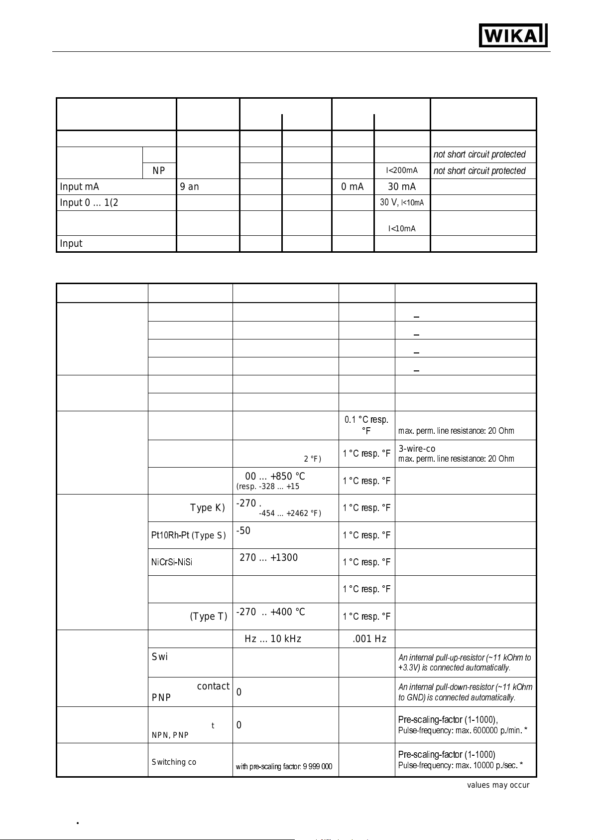
Measuring inputs:
Standard inputs for
Input type Signal Range Resolution
Standard-voltagesignal
0 ... 10 V 0 ... 10 V Ri > 300 kOhm
0 ... 2 V 0 ... 2 V Ri > 10 kOhm
0 ... 1 V 0 ... 1 V Ri > 10 kOhm
0 ... 50 mV 0 ... 50 mV Ri > 10 kOhm
Standard-currentsignal
RTD probes
Thermocouple
probes
4 ... 20 mA 4 ... 20 mA Ri = ~ 125 Ohm
0 ... 20 mA 0 ... 20 mA Ri = ~ 125 Ohm
Pt100 (0.1°C)
Pt100 (1°C)
Pt1000
NiCr-Ni (Type K)
Pt10Rh-Pt
NiCrSi-NiSi
(Type S)
(Type N)
-50.0 ... +200.0 °C
(resp. –58.0 ... +392.0 °F)
-200 ... +850 °C
(resp. -328 ... +1562 °F)
-200 ... +850 °C
(resp. -328 ... +1562 °F)
-270 ... +1350 °C
(resp. -454 ... +2462 °F)
-50 ... +1750 °C
(resp. -58 ... +3182 °F)
-270 ... +1300 °C
(resp. -454 ... +2372 °F)
0.1 °C resp.
°F
1 °C resp. °F
1 °C resp. °F
1 °C resp. °F
1 °C resp. °F
1 °C resp. °F
Note
3-wire-connection
max. perm. line resistance: 20 Ohm
3-wire-connection
max. perm. line resistance: 20 Ohm
2- wire-connection
Fe-CuNi (Type J)
Cu-CuNi(Type T)
-170 ... +950 °C
(resp. -274 ... +1742 °F)
-270 ... +400 °C
(resp. -454 ... +752 °F)
1 °C resp. °F
1 °C resp. °F
Frequency TTL-Signal 0 Hz ... 10 kHz 0.001 Hz
Switching contact
NPN
Switching contact
PNP
Rotation TTL-Signal,
Switching contact
NPN, PNP
Up/DownwardsCounter
* = with switc h i ng cont act acc ordi ngly to frequenc y i nput l ower values m a y occ ur
V1.3
02/2011
TTL-Signal,
Switching contact
NPN, PNP
0 Hz ... 3 kHz 0.001 Hz
0 Hz ... 1 kHz 0.001 Hz
0 ... 9999 U/min
0 ... 9999
with pre-scaling factor: 9 999 000
0.001
U/min
An internal pull-up-resistor (~11 kOhm to
+3.3V) is connected automatically.
An internal pull-down-resistor (~11 kOhm
to GND) is connected automatically.
Pre-scaling-factor (1-1000),
Pulse-frequency: max. 600000 p./min. *
Pre-scaling-factor (1-1000)
Pulse-frequency: max. 10000 p./sec. *
Page 28

Operating Instructions Digital Indicator DI15
•
- 28 -
Display range: (voltage-, current and frequency-measurement)
-1999 ... 9999 Digit, initial value, terminal value and decimal point position arbitrary.
Recommended range: < 2000 Digit
Accuracy:
Standard-signals: < 0.2% FS ±1 Digit (with 0 ... 50mV: < 0.3% FS ±1Digit)
RTD: < 0.5% FS ±1 Digit
Thermocouples: < 0.3% FS ±1 Digit (with Type S: < 0.5% FS ±1Digit)
Frequency: < 0.2% FS ±1 Digit
Point of comparison
Temperature drift: < 0.01% FS / K (from Pt100 – 0.1°C: < 0.015% FS / K)
Measuring freq.: approx. 100 readings / sec. (standard-signal) resp.
Outputs: 2 switching outputs, not electrically isolated,
Output type: selectable: low-side, high-side or push-pull
Connection specs.: low-side: 28V/1A; high-side: Ub/200mA
Response Time: <
Output-functions: 2-point, 3-point, 2-point with alarm, min-/max-alarm common or individual.
Switching points: arbitrary
Display: approx. 10 mm height, 4-digit red LED-display
Handling: 3 push-buttons, accessible after dismounting of the front panel or via interface
(at nominal temperature)
: ±1°C ±1 Digit
approx. 4 readings / sec. (temperature-measurement) resp.
approx. 4 readings / sec. (frequency, rpm at f >
20 msec. for standard signals
0.3 sec. for temperature, frequency (f > 4 Hz)
<
(at nominal temperature)
4 Hz) resp. accordingly f (at f < 4 Hz)
Interface:
EASY
BUS
-interface, electrically isolated
Power supply: 9 to 28 V DC
Current drain: max. 30 mA (without switching output)
Nominal temp.: 25°C
Operating ambient: -20 to +50°C
Relative Humidity: 0 to 80% r.H. (non condensing)
Storing temp.: -30 to +70°C
Enclosure: main housing: fibre-glass-reinforced noryl
front view-panel: polycarbonat
Dimensions: 24 x 48 mm (front-panel admeasurement).
Installation depth: approx. 65 mm (incl. Screw-in/plug-in clamps)
Panel Mounting: via VA-spring-clip.
Panel thickness: available from 1 to approx. 10 mm.
Panel cut-out: 21.7+0.5 x 45+0.5 mm (H x W)
Connection: via screw-in/plug-in clamps: 2-pol. for the interface and 9-pol for the other connections
Conductor cross-selection from 0.14 to 1.5 mm².
Protection class: front IP54, with additional o-rings IP65
EMC: 2004/108/EC, EN 61326, Emission (Group 1, Class B) and Immunity (industrial loca-
tions), additional errors: < 1% FS
In case of connecting cable/lines longer than 30 m or in case of cable/lines leaving the
building an additional ov erv olta ge pr otec t ion sh al l be provi ded.
V1.3
02/2011
 Loading...