

Page 1

Pressure and temperature
measurement
Manual
Hand-held thermometer CTH7000
Version 1.1, 03/14
Page 2

Page 3

CTH7000 Operating Instructions
Contents
CONVENTIONS USED IN THIS MANUAL ............................................................................................................. III
Structure of manual ................................................................................................................................................. iii
Terminology ............................................................................................................................................................... iii
Warnings and Notices ............................................................................................................................................. iii
IMPORTANT SAFETY INFORMATION ................................................................................................................. IV
IMPORTANT BATTERY CHARGER SAFETY INFORMATION ................................................................................ VI
IMPORTANT PROBE SAFETY INFORMATION .................................................................................................... VII
IMPORTANT DISPOSAL INFORMATION .......................................................................................................... VIII
European Union ...................................................................................................................................................... viii
Outside the European Union ................................................................................................................................ viii
1.0 INTRODUCTION ...................................................................................................................................... 1
1.1 Overview ...................................................................................................................................................... 1
1.2 Definitions and Terminology ..................................................................................................................... 1
1.3 Principles of measurement ....................................................................................................................... 2
2. SETTING UP THE CTH7000 ........................................................................................................................... 4
2.1 Safety information ...................................................................................................................................... 4
2.2 Unpacking the instrument ......................................................................................................................... 4
3. ABOUT THE CTH7000................................................................................................................................... 6
3.1 The Front Panel ............................................................................................................................................ 6
3.2 About the display screen .......................................................................................................................... 6
3.3 The Keypad .................................................................................................................................................. 6
3.3.1 Keypad overview ............................................................................................................................. 7
3.4 CTH7000 thermometer inputs ................................................................................................................... 9
3.5 Battery Pack .............................................................................................................................................. 11
3.5.1 Removing and replacing the battery pack ............................................................................... 11
3.5.2 Battery charger ............................................................................................................................... 12
3.5.3 Name plate(s) ................................................................................................................................. 15
3.5.4 USB Communication interface connector.................................................................................. 15
4. OPERATING THE CTH7000 ........................................................................................................................ 17
4.1 Instrument operating modes .................................................................................................................. 17
4.1.1 Measurement Mode ...................................................................................................................... 17
4.1.2 Menu Mode ( key) ....................................................................................................................... 18
4.1.3 Other menu options ....................................................................................................................... 21
4.1.4 Setting up Temperature measurement ....................................................................................... 34
4.1.5 Smart Probe review ........................................................................................................................ 34
5. INSTRUMENT MEASUREMENT RANGE ...................................................................................................... 36
5.1 Instrument measurement working range............................................................................................. 36
ASL operating instructions, model CTH7000 i
Page 4

CTH7000 Operating Instructions
5.2 Measurement Ranges ............................................................................................................................. 36
6. SMART PROBES ......................................................................................................................................... 38
6.1 About Smart Probes ................................................................................................................................. 38
6.2 How Smart Probes Work .......................................................................................................................... 38
6.3 Smart Probe Data Security ..................................................................................................................... 38
6.4 Smart Probe Calibration Supervisor ...................................................................................................... 38
6.5 Smart Probe Working Range Monitor ................................................................................................... 38
6.6 Smart Probe Errors .................................................................................................................................... 38
7. CALIBRATING THE CTH7000 ..................................................................................................................... 39
7.1 CTH7000 Instrument calibration ............................................................................................................. 39
7.2 Equipment ................................................................................................................................................. 39
7.3 Calibration procedure ............................................................................................................................ 39
8. COMMUNICATIONS INTERFACE .............................................................................................................. 41
8.1 Introduction ............................................................................................................................................... 41
8.2 USB Command syntax ............................................................................................................................. 41
8.2.1 Command terminators (CR) or (CR)(LF) ...................................................................................... 41
8.2.2 Command details .......................................................................................................................... 42
8.2.3 Example log output ........................................................................................................................ 44
9. SPECIFICATION ......................................................................................................................................... 46
9.1 Resistance thermometer measurement .............................................................................................. 46
9.2 Display ........................................................................................................................................................ 47
9.3 Functions .................................................................................................................................................... 47
9.4 Supply ......................................................................................................................................................... 47
9.5 Environmental ........................................................................................................................................... 47
9.6 Dimensions and weight ........................................................................................................................... 47
9.7 CE conformity ........................................................................................................................................... 47
10. CLEANING AND MAINTENANCE ......................................................................................................... 49
10.1 Cleaning .................................................................................................................................................... 49
11. SERVICE AND WARRANTY ................................................................................................................... 51
11.1 Technical Support .................................................................................................................................... 51
12. APPENDIX A .......................................................................................................................................... 52
12.1 USB device driver ...................................................................................................................................... 52
12.2 USB device driver installation ................................................................................................................. 52
ii ASL operating instructions, model CTH7000
Page 5

CTH7000 Operating Instructions
Conventions used in this manual
Structure of manual
The manual is divided into sections. Each section deals with a specific topic or related
topics. Sections are displayed in a regular, bold typeface, for example - 1.0 Introduction.
Sections are sub-divided into sub-headings, for example - 1.1 Features. These may also be
subdivided.
Terminology
The terms Precision thermometer, thermometer, CTH7000 and instrument are used
interchangeably in this manual.
Warnings and Notices
These appear in the body of the text, clearly displayed with a box surrounding the text.
The first word within the box displays the type - Warning or Note.
A Warning (double box) is designed to draw attention to an aspect that may cause
danger to the user or damage to the instrument. A Note (single box) is used to bring
special attention to something important requiring action or avoidance.
Copyright © 2013 ASL. All rights reserved.
Information in this document is subject to change without notice.
Reproduction or modification of the whole or any part of this document (in any form) without ASLs’ written
permission is forbidden (except for internal use by an authorised dealer or agent). Customers may make copies
for internal use only.
Whilst efforts have been made to ensure the accuracy of information presented here, ASL can assume no
responsibility for the accuracy of any information presented or the consequences of acting on this information.
ASL also disclaims any representation that the contents are current. However, ASL would be grateful for any
comments on the layout, accuracy or contents of this manual.
ASL shall not be liable for problems or damages arising from the use (or misuse) of items, servicing, equipment,
procedures or options supplied by other companies.
ASL. 4 Gatton Park Business Centre, Wells Place, Merstham, Redhill, RH1 3LG, U.K.
Phone: +44 (0) 1737 644 008. Fax: +44 (0) 1737 644 403. email info@aslltd.co.uk
ASL operating instructions, model CTH7000 iii
Page 6

CTH7000 Operating Instructions
Warning
The protection provided by the instrument may be impaired if the
equipment is not used in the manner specified.
Only replace items or components with an approved or
equivalent spare part. All spare and consumable parts are
available from ASL.
Warning
The instrument is NOT designed to be used in a potentially
explosive atmosphere or medical environment.
Warning
Do NOT open the case. There are no user serviceable parts inside.
Important safety information
Read and understand the user instruction manual before attempting to use the instrument.
The CTH7000 is a handheld, battery operated, thermometer. It must not be used for any other
purpose.
Do NOT use the instrument near water or in damp conditions
Do NOT clean the instrument with solvents
Do NOT insert objects into openings
Do NOT place the instrument, battery-pack or charger onto a hot or cold surface
Do NOT place any weight on top of the instrument, battery-pack or charger
Do ensure air can freely circulate around the battery compartment during charging
Do use the correct USB lead supplied
iv ASL operating instructions, model CTH7000
Page 7

CTH7000 Operating Instructions
Warning
Inspect cables and probes regularly, ensuring that their insulation
is not damaged
Warning
The instrument and batteries must be disposed of in accordance
with local regulations.
Warning
The instrument is sensitive to radiated noise and care must be
taken to ensure a clean mains supply and controlled EM
environment.
General warning symbol. This indicates that a
hazardous condition or general danger may exist.
You must read the relevant sections in the User
Manual before using the instrument.
Refer to manual symbol. When you see this symbol
on the instrument it means that there is more
information relating to this in the User Manual.
ASL operating instructions, model CTH7000 v
Page 8

CTH7000 Operating Instructions
Warning
Only use the battery charger supplied. Use of any
other charger will invalidate the warranty and may
lead to the danger of overheating and to permanent
instrument damage.
The battery charger supplied must NOT be used with
other equipment.
Warning
Do NOT cover the battery charger, battery pack or
instrument during charging or use.
Ensure air is free to circulate around these items during
charging.
Warning
Do NOT short the contacts on the battery
compartment with any metallic object.
Important battery charger safety information
The battery charger and battery pack are supplied for use with the CTH7000.
vi ASL operating instructions, model CTH7000
Page 9

CTH7000 Operating Instructions
Warning
Because of the nature of the instrument, probes can
be excessively HOT or COLD during use. Take suitable
precautionary measures when handling probes.
Take care that you (and other people working in the
same area) do not come into contact with the
metallic probe or the insulating sheath near the
probe, which will also be hot/cold.
Precautions apply both during use or when moving
the probe from one position to another.
Warning
Probes may be immersed in various chemicals during
use. Some of these chemicals may be dangerous or
harmful (even when the probe is cold).
Always assume that the probe has been used this way
and DO NOT touch the probe without suitable
protective clothing.
Important Probe safety information
Care must be taken with probes used with the instrument. The following safety information
must be observed.
Do NOT lift the CTH7000 by any of the leads
Do ensure that long probe-leads are kept away from areas where people could trip
over them or become tangled in them
Do ensure the probe-leads are kept in good condition
ASL operating instructions, model CTH7000 vii
Page 10
CTH7000 Operating Instructions
European Union
This symbol means that the product to be disposed of
should not be mixed with commercial or general
household waste. Used products must be treated
separately in accordance with legislation that requires
the proper treatment, recovery and recycling of the
product.
If you wish to discard the product, then please contact
your dealer, supplier or representative who will advise the
correct procedure for disposal.
Disposing of the product correctly will help to save
valuable resources and prevent environmental damage.
Outside the European Union
The symbol only applies within the European Union. If you
need to discard the product, then please contact your
dealer, supplier or the local authorities and ask for the
correct method of disposal.
Important disposal information
If you are responsible for disposal, then please note that this product may contain
materials that are regulated in their disposal due to environmental considerations. The
presence of these materials is consistent with global regulations applicable at the time
this product was placed on the market.
viii ASL operating instructions, model CTH7000
Page 11

CTH7000 Operating Instructions
1.0 Introduction
1.1 Overview
The CTH7000 Precision Handheld Thermometer is a high precision instrument designed for
laboratory, commercial and industrial temperature measurement and calibration
applications.
Features include:
Two input channels
A large graphic LCD display for excellent viewing of temperature measurement
values and instrument settings
USB communication interface as standard for automated monitoring and calibration
applications
Calibration against traceable external standards
The CTH7000 will operate with all 4-wire Pt100 (100 ohm) Platinum Resistance Thermometers
(PRTs) and with virtually all thermistors.
Temperature measurement units are user-selectable and can display C, F, K and .
Overall system accuracy will depend on the sensor quality and calibration - see the
specification section.
1.2 Definitions and Terminology
i. 0°C = 273.15 K
ii. 1 mK (milli-Kelvin) = 0.001C (one milli-degree Celsius)
iii. 1 milli-degree C = 0.001 C = 1mC = 1mK = 1.8mF
iv. 1 milli-degree F = 0.001F = 1mF = 0.56mK = 0.56mC
v. Alpha, or , is the temperature coefficient, or temperature sensitivity, of the platinum
wire used in PRTs. In general, the greater the alpha value, the better the PRT
thermometer measurement reproducibility, stability and performance
vi. Abbreviations for platinum resistance thermometers include -
PRT (Platinum Resistance Thermometer)
Pt100 (PRT with nominally 100 resistance at 0C)
RTD (Resistance Temperature Device)
vii. Abbreviations for thermistor thermometers include -
therm
ASL operating instructions, model CTH7000 1
Page 12

CTH7000 Operating Instructions
s
t
st
V
V
RR
Note
For non-Smart probes, always check that the
coefficients are correctly set for the probe being used.
Failure to do so, may lead to incorrect measurements.
viii. System accuracy refers to the overall, combined accuracy of the CTH7000 and
thermometer.
1.3 Principles of measurement
The CTH7000 measures the voltage (Vt) developed across the unknown sensor resistance (Rt)
and the voltage (Vs) across a stable internal reference resistance (Rs). The voltages are
proportional to the resistances so the thermometer resistance is derived from –
This technique achieves immunity from slow moving time and temperature drifts in the
electronics, as it is not affected by voltage measurement gain variations or current source
fluctuations.
In the same way that AC resistance measurement eliminates thermal EMFs, switched DC
achieves a similar advantage. Switched DC works by reversing the current flow on alternate
measurement cycles and taking the average value, thereby cancelling any thermal EMF
offsets from the measurement.
For PRTs, the relationship between resistance and temperature varies slightly from one PRT to
another. Therefore, no matter how accurately the CTH7000 measures the PRT resistance, if
the relationship between resistance and temperature for a particular PRT is not known,
accurate temperature measurement is not possible. For thermistors, the relationship depends
totally on the thermistor type and specifications.
The CTH7000 uses PRT and thermistor calibration data to overcome this problem and
calculates the result from temperature conversion functions stored in either the sensors
‘SMART’ connector or the CTH7000’s internal non-volatile memory. This method enables the
CTH7000 to convert resistance to temperature, uniquely for each sensor used.
It is very important, therefore, that a sensor without a ‘SMART’ connector is used on a properly
configured input channel and that the probes’ coefficients are correctly entered into the
instrument.
2 ASL operating instructions, model CTH7000
Page 13

CTH7000 Operating Instructions
System accuracy is a combination of the CTH7000 accuracy in measuring sensor resistance
and the calibration uncertainty placed on PRTs and thermistors by the calibrating laboratory.
ASL operating instructions, model CTH7000 3
Page 14

CTH7000 Operating Instructions
1
2. Setting up the CTH7000
2.1 Safety information
Please read the safety information section before attempting to operate the
CTH7000.
2.2 Unpacking the instrument
When you unpack the CTH7000 thermometer, check that the following items are present
before using the instrument1 -
CTH7000 precision thermometer
Battery charger
Operator’s handbook on CD
Calibration certificate
USB lead
Please contact the ASL Technical Services Group immediately if any of these items are
missing or damaged.
Please retain the packaging. In case of return, servicing or calibration, use the original
packaging. Failure to do so may invalidate the warranty and/or incur additional costs
outside the warranty period. Please contact your agent, dealer or supplier when the original
packaging is unavailable.
Thermometer probes (if ordered), will be supplied separately
4 ASL operating instructions, model CTH7000
Page 15

CTH7000 Operating Instructions
This page is intentionally left blank.
ASL operating instructions, model CTH7000 5
Page 16

CTH7000 Operating Instructions
USB
Keypad
LCD display
Inputs at rear
3. About the CTH7000
This section will introduce you to the features and functions of the CTH7000 Precision Thermometer.
Each of the features is explained in turn. Once the CTH7000 has been set-up to your particular
requirements, all the commonly used functions are available using single key-strokes.
3.1 The Front Panel
Figure 3.1- Front panel
3.2 About the display screen
The large graphic LCD screen is your direct link to the instrument, presenting you with the
measurement results and information or menus to set and control the instrument.
The LCD screen is designed for reflective-viewing under normal ambient lighting; a backlight
is provided for use when ambient conditions are darker.
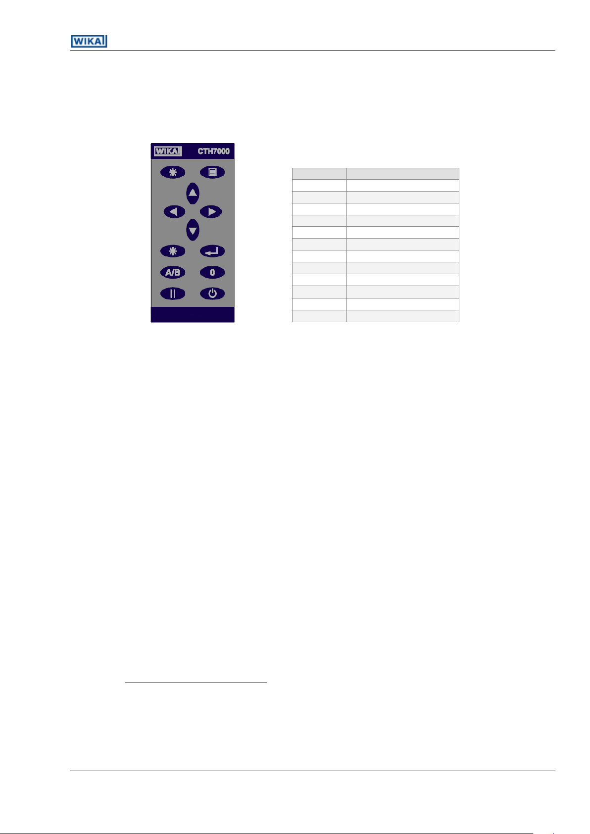
3.3 The Keypad
The CTH7000 keypad is shown below. The keys are used to select the various menu options.
Generally, no more than two menu levels are used. A few (infrequently used options) require
three menu levels. Operation is simple once you are familiar with instrument.
6 ASL operating instructions, model CTH7000
Page 17
CTH7000 Operating Instructions
2
3
4
Key
Function
Menu display
Backlight
Up arrow
Down arrow
Left arrow
Right arrow
Clear (view statistics)
Enter
A/B
A/B channel select
0
Zero (offset) reading
Hold reading
Power on/off
It may help to have the instrument to hand when reading through these sections.
Refer to section 4 for a detailed description of how to use the keys to operate the instrument
Figure 3.3 – CTH7000 Keypad
3.3.1 Keypad overview
The red Power ( ) key turns power on and off2 to the CTH7000.
The CTH7000 uses a menu system. The Menu ( ) key is located at the top right of keypad.
Use the Menu key to access to the less frequently used CTH7000 functions. The four Arrow (
) keys are used to navigate through the menus3; the Enter ( ) and Clear ( ) keys
are used to act on the menu selections4.
The Backlight () key located at the top left of the keypad provides LCD illumination when
the ambient light-level is too low for normal viewing.
The A/B key is used to select one of the two channels or the difference (A – B)
The Zero ( 0 ) key is used to provide relative (offset) readings.
The Hold ( ) key is used to freeze the current reading.
ASL operating instructions, model CTH7000 7
The CTH7000 may also be set to power-off after a preset period.
The Up () and Down () keys can be used to change the displayed units
The Clear ( ) key is also used to view CTH7000 statistics; press once to select the statistics page. Press any
key to return.
Page 18

CTH7000 Operating Instructions
This page is intentionally left blank.
8 ASL operating instructions, model CTH7000
Page 19

CTH7000 Operating Instructions
5
Channel B (blue)
Channel A (red)
PRT or thermistor
3.4 CTH7000 thermometer inputs
There are two input channels; two 5 pin DIN input-sockets are located at the rear of the
instrument. These are designed to take either PRT or thermistor probes. Channel A is colour-
coded red. Channel B is colour-coded blue.
Figure 3.4 - Rear panel
Either channel can accept either Smart or Passive probes; any combination of probes can
be use together. Smart probes (described in section 6.0) contain their own calibration
information and communicate this to the CTH7000 as soon as they are used. Passive probes
do not contain calibration information and the CTH7000 must be set-up with the calibration
information for each probe used (and each time the probe is changed).
Probe connection information for both PRTs and thermistors5 is shown below (viewed looking
towards the sockets) -
Figure 3.4.1 4-Wire SMART probe (SMP) PRT/thermistor input
Two wire PRTs/thermistors must have pins1 & 2 connected together and also pins 4 & 5 connected together.
ASL operating instructions, model CTH7000 9
Page 20

CTH7000 Operating Instructions
PRT or thermistor
Figure 3.4.2 4-Wire Passive probe PRT/thermistor input
10 ASL operating instructions, model CTH7000
Page 21

CTH7000 Operating Instructions
Battery pack removed
Battery charger input
connector
USB communications
connector
3.5 Battery Pack
Figure 3.5 - Base of the CTH7000 showing the battery back removed
The instrument operates from battery power. The battery pack is replaceable. A low battery
indication is shown on the LCD when the battery needs recharging; the instrument also
audibly indicates a low battery condition. The battery may be d when attached to the
instruments.
3.5.1 Removing and replacing the battery pack
To remove the battery pack, press the latching tab and slide the battery pack backwards.
See figure 3.6 for details.
ASL operating instructions, model CTH7000 11
Figure 3.6 – Removing and replacing the battery pack
Page 22

CTH7000 Operating Instructions
Warning
Only use the battery charger supplied.
Use of any other charger will invalidate the warranty
and may lead to the danger of overheating and to
permanent instrument damage.
Warning
Take care not to short the battery packs’ contacts
with any metal object when the pack is not
connected to the instrument.
Warning
Take care not trap any part of your hand when
closing the battery compartment.
Warning
Never cover the battery pack or charger during use.
To replace the battery pack, place the pack in position before sliding home. See figure 3.6
for details. Check that the battery pack is securely in position before using the instrument.
3.5.2 Battery charger
Please observe the following warnings (repeated from the front of the manual).
The batteries are located in a removable pack located on the base of the instrument.
The battery pack contains two NiMHi cells (in series) and a charger control circuit. The
battery pack must only be charged using the unit supplied.
The battery pack has a socket on its side that accepts the charger’s connector. A LED
(viewable through an aperture on the top-rear of the pack) indicates the charger status –
see figure 3.7.
12 ASL operating instructions, model CTH7000
Page 23

CTH7000 Operating Instructions
Note
Disconnect the charger when not charging the battery
pack.
Note
Performance may degrade if the batteries are charged during use.
6
Charge indication
LED aperture
The battery charger is provided with various interchangeable mains connectors; select the
one that you require - see the charger PSU pack for details.
3.5.2.1 Charging the battery pack
The CTH7000 battery pack may be charged during instrument use, when the instrument is off,
or when the pack is detached from the CTH7000.
Please follow the instructions below to ensure that the battery pack is fully charged (LED
charge status is shown in the table below) –
Turn off power to the adapter before plugging it into the side of the battery pack.
Figure 3.7 – Charge indication LED
Switch on the power adapter (6 Vdc), ensuring the LED flashes orange.
Leave the battery pack to fully charge. An overnight charge of about 10 hours (for a
flat battery with the CTH7000 off6) will ensure that the pack is fully charged (the
Allow 5 minutes before use if the batteries are completely flat.
ASL operating instructions, model CTH7000 13
Page 24

CTH7000 Operating Instructions
Status LED
LED
indication
Description
Slow orange flash (1 s)
Trickle charge
Fast orange flash (0.2 s)
Fast charge
Solid green
Charged (trickle charge enabled)
Slow red flash (1 s)
Low battery temperature (trickle
charge enabled)
Solid red
PSU voltage too high8
Fast red flash (0.2 s)
Hardware error9
7
8
9
actual time depends on the initial battery state)7. Charge time will increase if the
CTH7000 is used during this period.
Turn off and remove the power adapter after charging is complete.
The meaning of the various LED indications is shown on below –
Charge times may increase at higher ambient temperatures.
The PSU input voltage must be less than10 volts (6 volts PSU supplied).
Refer to customer services.
14 ASL operating instructions, model CTH7000
Page 25

CTH7000 Operating Instructions
Note
Communication via an USB cable connected to a PC
may cause the CTH7000 to be noisy.
ASL can accept no responsibility for any performance
degradation when connected to a PC.
3.5.3 Name plate(s)
The instrument rating plate shows the instruments maximum power consumption and
instrument serial number.
The label on the battery charger shows its operating voltage, current and frequency.
The label on the battery charger shows its operating voltage, current and pack’s serial
number.
3.5.4 USB Communication interface connector
The USB connector is fitted as standard (see figure 3.1). Communication requires the
installation of the USB driver on a PC. See the separate information supplied on the CD. A
standard USB cable is supplied with the CTH7000.
The instrument can be used with ASL’s ULOG program (supplied on the CD) or simply used to
transmit ASCII data, which may be recorded using a simple terminal program.
ASL operating instructions, model CTH7000 15
Page 26

CTH7000 Operating Instructions
This page is intentionally left blank.
16 ASL operating instructions, model CTH7000
Page 27

CTH7000 Operating Instructions
10
ChA s:CTH7000-1234
PRT4
Bat
22.479
oC
ITS-90 10:24:33
Smart probe serial number
Current reading with units displayed
Time of day
Reading units
Low battery indication
Channel (ChA) using a
4 wire sensor (PRT4)
Probe conversion
4. Operating the CTH7000
4.1 Instrument operating modes
The instrument has two operating modes -
Measurement Mode which displays the measurement readings and status information
Menu Mode which lets you select and alter the instrument operation and its settings
4.1.1 Measurement Mode
In Measurement Mode, the LCD displays the current reading (temperature or resistance), the
unit symbol, the channel and type of sensor selected (and conversion method); the time of
day is also shown10. This is the normal operating display for the CTH7000. The display will look
similar to the one shown below -
This display will always reflect the operation of the instrument, showing the current reading
and settings. Readings are updated at the normal conversion rate of one every two seconds.
ASL operating instructions, model CTH7000 17
The time will be replaced by ‘Logging’ or ‘Remote’ when these modes are selected
Page 28

CTH7000 Operating Instructions
11
SMP Probe Info
SMP Coefficients
Units
Channel A
Channel B
Logging
Statistics
Settings
System
Units
Channel A
Channel B
Logging
Statistics
Settings
System
Current menu highlighted
4.1.2 Menu Mode ( key)
In menu mode, the LCD displays the various options available to control CTH7000 operation.
Press the Menu key ( ) to select the menu screen.
The reverse-video background indicates the menu that will be selected should the Enter key (
) be pressed (Units selection in the example above). Further menu options will follow once
the Enter key has been pressed.
Press the Up ( ) and Down ( ) keys to move through the options. Pressing an up/down key
will move the reverse video selection one line up or down one line11. Once the selection is
corrrect, press the Enter key. So, for example, to change channel A options, press the Down
key ( ) once to obtain the following display -
Now press the Enter key ( ) to select this option. The following screen will appear (when a
Smart probe is connected to channel A). The display will be different for a passive probe –
Press the Down key ( ) once to obtain –
The selection line will wrap round from top to bottom (or bottom to top) on repeated arrow presses.
18 ASL operating instructions, model CTH7000
Page 29

CTH7000 Operating Instructions
SMP Probe Info
SMP Coefficients
ChA(s) CVD
R0 +1.00000e+02
A +3.90830e-03
B -5.77500e- 03
Read Only
Up/Down Move
Clear Exit
Now that this menu has been highlighted, press the Enter key ( ) once to obtain –
In this example, pressing the Up or Down key will display more of the Smart probes’
coefficients.
Pressing the Clear key ( ) will return the display to the previous menu. Press the Clear key (
) once more to return to Measurement mode. Pressing the Enter key ( ) will return the
CTH7000 immediately to Measurement Mode (generally applies to all lower level menu
options).
No changes can be made in this example. When changes are made, all settings are stored
and retained when power is removed.
Refer to the sections on Smart Probes for more details.
4.1.2.1 Selecting the thermometer input channel and differential mode (A/B key)
The channel Select key ( A/B ) is used to change between channels and also to select the
differential mode ( A – B ). The channel selection order is –
A missing probe will be indicated on the display by a series of dashed lines.
ASL operating instructions, model CTH7000 19
Channel A Channel B Channel (A – B) Channel A
Page 30

CTH7000 Operating Instructions
ChA s:CTH7000-1234
PRT4
0.009
( 022.048) oC
Offset 10:24:33
Zero offset value
Absolute value (flashing)
Zero mode indication
alternates with the conversion
C hA * 22.048
-C hB 22.090
-0.042
oC
CVD 11:53:08
Probe conversion for
current channel
Individual channels
Differential mode
indicator
In differential mode (when both channel A and channel B have probes connected), the
screen will look similar to the following example. The asterisk next to the ChA and ChB
legends will alternate as readings are updated.
The probe conversion indicator (bottom-left) displays the conversion method for the current
reading (and so will alternate if the two channels have different conversion methods).
4.1.2.2 Selecting relative temperature measurement (0 key)
The instrument displays a reading value relative to a fixed offset in Zero (or relative) mode.
Press the Zero ( 0 ) key to select this mode.
In Zero mode, the instrument stores the last reading (at the time of Zero key press) to subtract
from all subsequent readings. It continues doing this until it is either cancelled by pressing the
Zero key again or until power is removed.
Zero mode may be used on differential measurements (A – B). In this case, the difference is
set to zero at the time the key is pressed and the absolute value in the example above, is
replaced by the absolute difference value.
To cancel the relative measurement mode, press the Zero ( 0 ) key again. Zero mode is
cancelled when power is turned off.
20 ASL operating instructions, model CTH7000
Page 31

CTH7000 Operating Instructions
Note
When the CTH7000 is battery operated, using the
backlight will dramatically reduce battery life (by
about 30% if used continually at full-brightness).
ChA s:CTH7000-1234
PRT4
22.479
oC
Hold 10:24:33
Hold mode indication
alternates with the conversion
4.1.2.3 Selecting run/hold mode ()
Instrument measurements stop completely when Hold mode is active. This is indicated on the
bottom-left of the display where Hold mode indication alternates with the current conversion
method, providing a flashing indication. Hold mode may be used when the CTH7000 is in
differential mode.
Press the Hold () key to alternate between run and hold modes. Hold mode is cancelled
when power is turned off.
4.1.2.4 Backlight key ()
Press the Backlight key () to illuminate the display. Once on, the backlight will go
automatically off after about 10 seconds; alternatively, press the key again to turn it off.
The brightness level can be set on the Settings menu (see later section). Reducing the
brighness value will increase battery life when the backlight is used.
4.1.3 Other menu options
This section describes the other options available through menu selection. Generally, these
options are set once and then altered rarely. The set-up is stored in non-volatile memory and
recalled when power is reapplied.
In the following sections, the top level menu is shown, followed by the sub-menu(s) that it
selects.
ASL operating instructions, model CTH7000 21
Page 32

CTH7000 Operating Instructions
12
12
Units
Channel A
Channel B
Logging
Statistics
Settings
System
Celcius
Fahrenheit
Kelvin
Ohms
Units
Channel A
Channel B
Logging
Statistics
Settings
System
Probe Type
Temp Conv
Coefficients
4.1.3.1 Selecting Units
Press the Menu key ( ) to change the measurement units. The Units menu will be
highlighted. Press the Enter key once to reach the Units selection menu.
Select the units required with the Up/Down keys and then press the Enter key. Units of Celsius
(°C), Fahrenheit (°F), Kelvin (K) or Resistance () can be selected; the current units are shown
on the Measurement Menu screen. Changing units will automatically clear any statistics. The
current measurement units are retained when power is removed.
Having selected the new units, press the Menu key to return to Measurement Mode.
4.1.3.2 Channel options menu (Channel A or Channel B)
Operation of channel A and channel B is identical; Press the Enter key to select the sub-menu
–
a) Probe type
The sub-menu is used to select the type of probe attached. There are two completely
different probe types - either PRT or Thermistor. This probe selection sub-menu is used
to set these options.
22 ASL operating instructions, model CTH7000
Alternatively, the Up () and Down () keys can be used to change the displayed units
Page 33

CTH7000 Operating Instructions
13
PRT 4 wire
NTC Thermistor
DIN
CVD
ITS - 90
Passcode = 0000
Left/Rt selects
Up/Down changes
Enter OK
The currently selected sensor type is always shown at the top left of the measurement
screen (see the example shown in section 4.1.1).
Channel A is always used for the PRT probe and channel B is always used for the
Thermistor probe.
Use the Down key (twice) to select the thermistor probe on channel B. When the
menu is entered again, the thermistor line will be highlighted.
Selection of PRTs is more involved since the conversion method has to be set at the
same time as the probe is changed. Selecting one of the PRT menus will display the
passcode screen –
b) Conversion method
Use the Up/Down arrow keys to increment or decrement the passcode. Use the Enter
key once the correct passcode has been set; this procedure helps to prevent
inadvertent changes. The default passcode setting13 is 4300.
This screen will only appear once the correct passcode has been entered. This screen
shows that the CVD conversion method is currently selected. Use the Up and Down
keys to highlight the required conversion method and then use the Enter key to select
it.
This can be changed using the Settings menu; keep careful note of the new value if changed. A lost
ASL operating instructions, model CTH7000 23
password can be retrieved, but you will need to contact ASL directly for further information.
Page 34

CTH7000 Operating Instructions
Note
Smart probes use their own internal calibration data.
The instrument coefficients are ignored when a Smart
probe is attached.
For PRTs, the instrument provides three standard algorithms for converting resistance
to temperature. The choice of algorithm will depend on the type of PRT and its
calibration –
DIN (1992) - used for un-calibrated industrial PRTs with 0.00385 ‘alpha’
value, to provide a conversion of resistance to temperature in
accordance with BS EN60751 (ITS 90) standard
CVD coefficients - Callendar van Dusen used for calibrated industrial or
low alpha PRT’s of 0.00385
ITS-90 coefficients - used for calibrated high alpha PRT’s of values
0.003926 to 0.003928
The choice of conversion method and the relevant coefficients are set from this
menu.
For Thermistors, the instrument provides one standard algorithm for converting
resistance to temperature –
Steinhart and Hart
c) Probe coefficients
Both PRT and Thermistor probes must be correctly calibrated to produce their most
accurate performance. The CTH7000 can store calibration data for each of the two
channels; this information is only required when passive probes are being used. When
Smart probes are used, the calibration data is stored in the probe and the coefficients
held in the CTH7000 are not required or used.
When passive probes are used, correct entry of the parameter values is absolutely
critical to obtain accurate readings. For this reason, the coefficients menu is passcode
protected. The passcode screen (below) will appear once the Coefficients menu has
been selected. Use the Up and Down arrow keys to increment or decrement the
passcode value.
24 ASL operating instructions, model CTH7000
Page 35

CTH7000 Operating Instructions
14
15
Probe Type
Temp Conv
Coefficients
Passcode = 0000
Left/Rt selects
Up/Down changes
Enter OK
CHA ITS90
Rtp +1.00000 e+02
A +3.90830e-03
B -5.77500e - 07
Up/Down move
Enter edit
Clear exit
EDIT
Rtp +1.00000 e+02
A +3.90830e-03
B -5.77500e - 07
Left/Rt selects
Enter changes
Clear saves
Use the Enter key once the correct passcode has been set; this procedure
helps to prevent inadvertent changes. The default passcode setting14 is 4300.
The coefficient edit screen will appear once the correct passcode has been
entered. In this example, the edit screen for CVD coefficients is shown; the first digit
of the R0 coefficient will be highlighted (in this case the ‘1’). This is the current cursor
position. Use the Up and Down keys to change the value under the cursor. Once this
value is correct, use the Left and Right keys to select the next digit to set. Use the
Enter key once the complete coefficient has been edited correctly; alternatively use
the Clear key to move on to the next coefficient15. The coefficients will be set to the
value shown when the Enter key is pressed.
Once the first coefficient has been edited, the screen will scroll (if more than three
coefficients are required). Note that DIN coefficients cannot be edited.
Follow a similar procedure for entry of NTC thermistor coefficients.
4.1.3.3 Data logging menu
The CTH7000 can log data. Logging status is always shown at the bottom right-hand of the
measurement screen (see section 4.1.1).
This can be changed using the Settings menu; keep careful note of the new value if changed. A lost
password can be retrieved, but you will need to contact ASL directly for further information.
Use the Clear key repeatedly to exit without changing any of the coefficients.
ASL operating instructions, model CTH7000 25
Page 36

CTH7000 Operating Instructions
16
Logging
Channel A
Channel B
Logging
Statistics
Settings
System
Stop
Review
Logging
Channel A
Channel B
Logging
Statistics
Settings
System
Start
Setup
Review
Clear
Data can be logged at regular intervals (the interval is set when Setup selected), reviewed
and logging can be turned on and off.
Press the Enter key to select the sub-menu used to set the various logging options.
Note that there are a finite number of data points that can be stored, so eventually, any old
results will be overwritten as the selected log will eventually wrap-round – i.e. the oldest
reading will be overwritten first16.
Use the Start menu item to begin logging.
Select Clear to clear the log and return to the main menu.
Selecting Stop (see below) will halt logging. Logging can be restarted using the Start menu
item (logging will then continue after the last point previously logged).
Only two menu options will be available when the instrument is logging.
After approximately 8000 points when continuously logging; starting and stopping the log will decrease this
number points available.
26 ASL operating instructions, model CTH7000
Page 37

CTH7000 Operating Instructions
Logging
Channel A
Channel B
Logging
Statistics
Settings
System
Start
Setup
Review
Clear
10 – 18 April 0
22:27 A 120.000F
22:29 A 120.000F
22:31 A 120.000F
22:33 A 120.000F
22:35 A 120.000F
22:37 A 120.000F
Dn Next Pg
Use the down key to
select the next page
Hour of reading &
Reading and units
Minutes/seconds and
channel
Current page
History Setup
MM:SS
Intvl: 00:00:02
a) Review
Results similar to the following example will appear once the Review key has been
pressed.; exact details will vary with the instrument setup. The example shows channel
A results logged at 2 second intervals.
Use the Down key to scroll through the logged readings a page at a time.
Press the Clear key ( ) to return to the main menu screenu.
b) Setup
Use the setup menu to set the logging interval. Either select the required interval with
ASL operating instructions, model CTH7000 27
the Enter key or use the Clear key to return to the measurement menu.
The interval can be set anywhere between 1 second and 59 minutes 59 seconds (a
logging interval of 2 seconds is shown in the example). Selecting an interval of 00:00
will log data as fast as possible; select an interval that best matches your
requirements. Logging with a larger data intervals effectively increases the total
period for which data can be logged.
Page 38

CTH7000 Operating Instructions
17
Units
Channel A
Channel B
Logging
Statistics
Settings
System
Exit
Clear
ChA
Mn 23.456
Mx 23.559
Mean 23.405
Std dev 0.010
Total 10
Logging will stop when the power is turned off.
4.1.3.4 Statistics menu
The CTH7000 provides statistics on the data it is collecting. Press the Enter key to select the
statistics sub-menu.
Statistical information is calculated continuously from the moment statistics are cleared (see
sub-menu). Changing any parameter that affects the calculation (e.g. units) will
automatically clear and restart calculation.
The Exit option is used to return to the Measurement Menu after viewing statistics.
Alternatively, press the Clear key ( ) to return to Measurement Menu without clearing
statistics.
The minimum, maximum, mean, standard deviation and total number of readings are
displayed on this screen17. Select Clear to immediately clear and restart the statistical
calculations.
28 ASL operating instructions, model CTH7000
The maximum and minimum values are also displayed continuously on the measurement menu screen.
Page 39

CTH7000 Operating Instructions
Units
Channel A
Channel B
Logging
Statistics
Settings
System
Brightness
Timeouts
Time & Date
ADC Mode
Brightness
Timeouts
Time & Date
ADC Mode
50 & 60 Hz Reject
50 Hz Reject
60 Hz Reject
Brightness
Timeouts
Time & Date
ADC Mode
Set Brightness
Use Up/Down Keys
Any key to Exit
49
4.1.3.5 Settings menu
Several operational parameters can be changed in the Settings menu. Press the Enter key to
select the Settings sub-menu. Foe example, to change the ADC mode (50/60 Hz) setting -
CTH7000 has been set to 50 Hz & 60 Hz reject (rejection filter) by default. Select 50 Hz or 60 Hz,
depending on the operational mains frequency in your area. This can provide better noise
rejection. See the menu screen shown below.
a) Brightness
Selecting this option allows the brightness of the LCD backlight to be adjusted. Use
the Enter key once you are happy with the backlight intensity. Use the Clear key to
exit without altering the set value.
ASL operating instructions, model CTH7000 29
Page 40

CTH7000 Operating Instructions
Note
When the CTH7000 is battery operated, using the
backlight will dramatically reduce battery life. The
current used increases as the backlight intensity rises.
18
Brightness
Timeouts
Time & Date
ADC Mode
2005:Aug:20
12:23:38
Left/Rt selects
Up/Down changes
Clr/Enter exits
Brightness
Timeouts
Time & Date
ADC Mode
No Timeout
5 Minutes
15 Minute
30 Minutes
1 Hour
4 Hours
8 Hours
b) Timeouts
The CTH7000 can be set to timeout after a preset period (to save battery life); by default the
timeout is off. Selecting this option allows the various timeout values to be set. Use the Up
and Down keys to select the required timeout and then press the Enter key to select it (or use
the Clear key to return to the Measurement Menu).
c) Time/Date menu
The CTH7000 contains a real-time clock18. The Time/Date menu is used to set the clock.
The menu keys are used to change the settings. Use the Up and Down keys to alter the value
under the reverse-video cursor. Once the correct value is set, use the Right and Left keys to
move to the next field. Use the Clear key to exit without changing the values. The Enter key
will set the clock to the new values.
It is important to set the clock correctly when using data logging.
d) ADC mode
See the example at the start of this section.
30 ASL operating instructions, model CTH7000
The clock battery is contained internally; the battery pack is not used for the real time clock.
Page 41

CTH7000 Operating Instructions
19
Units
Channel A
Channel B
Logging
Statistics
Settings
System
Change Passcode
Calibration
Factory Defaults
Diagnostics
Change Passcode
Calibration
Factory Defaults
Diagnostics
Old code = 0000
Left/Rt selects
Up/Down changes
Enter OK
Current = 4300
Any key to exit
4.1.3.6 System menu
The settings menu allows the remainder of the instrument parameters to be set.
a) Change Passcode
Selecting this option allows the CTH7000 passcode to be set to another value19. The current
passcode has to be entered before it can be altered. The passcode screen will always show
the value ‘0000’ when it is first displayed; use the Up and Down keys to change this to the
current passcode value. Press Enter when the current passcode is correct. The new value can
then be set. In the example below, the passcode is ‘4300’.
Set to 4300 by default
ASL operating instructions, model CTH7000 31
Page 42

CTH7000 Operating Instructions
Note
Selecting this option will overwrite the instrument
calibration data. Do not attempt to do this unless you
have the correct equipment, environment and suitably
trained personnel.
Note
Specialised equipment is required to proceed further
with this procedure.
Change Passcode
Calibration
Factory Defaults
Diagnostics
Do Calibration
Edit Resistors
Edit Calibration
Reset Cal
b) Instrument calibration
Selecting this option allows the CTH7000 to be calibrated; this option will overwrite and
replace the exiting calibration data. The correct equipment, environment and accurately
calibrated resistors are required. For this reason, a passcode (9900) has to be entered first –
32 ASL operating instructions, model CTH7000
Page 43

CTH7000 Operating Instructions
Note
Selecting this option will overwrite all instrument
calibration data and settings. Do not attempt to do this
unless you have the correct equipment, environment
and suitably trained personnel.
Change Passcode
Calibration
Factory Defaults
Diagnostics
Passcode = 0000
Left/Rt selects
Up/Down changes
Enter OK
Clear coeff’s
Restore factory
defaults?
Enter if yes
Clear for no
Factory defaults
The instrument parameters can be set to the factory defaults. Selecting this option will
overwrite any exiting calibration data. For this reason, a passcode (9900) must be entered
(see below) -
c) Diagnostics
Not available for use.
ASL operating instructions, model CTH7000 33
Page 44

CTH7000 Operating Instructions
Note
The CTH7000 may take up to 5 seconds to recognise
and acquire data from the Smart Probe after switch-on
before displaying a measurement.
4.1.4 Setting up Temperature measurement
To enable accurate resistance to temperature conversion to be carried out by the
instrument, PRT or characterisation data is required for both –
temperature conversion algorithm, and
temperature conversion algorithm coefficients
For Thermistors, characterisation data is only required for –
temperature conversion algorithm coefficients
The data can be stored in either a Smart probe or the instruments’ internal non-volatile
memory, each thermometer input channel stores one set of PRT/Thermistor characterisation
data. See the relevant section above for details on entering the data.
4.1.4.1 Temperature measurement with Smart probe (s)
If a Smart probe is detected on a selected input channel, the PRT calibration data is loaded
directly from the Smart probe. Smart probe data always takes precedence over the internal
CTH7000 coefficient data (but does not overwrite the instrument data).
4.1.4.2 Instrument calibration
This is not usually a customer option; refer to separate documentation.
4.1.4.3 Firmware Version
The firmware version is shown at the bottom of the LCD when the instrument is first powered.
4.1.5 Smart Probe review
The Smart probe data can be reviewed, but not changed on the CTH7000. The Smart probe
data contains the following information -
Version Smart probe data format
Lock Password protection state
00 = Smart probe data locked can not be changed from the instrument
01 = Smart probe data unlocked can be changed from the instrument
34 ASL operating instructions, model CTH7000
Page 45

CTH7000 Operating Instructions
Cal type Selected method of resistance to temperature conversion algorithm to use,
DIN, ITS90, CvD or Steinhart and Hart (for thermistors)
Cal date Date of the Smart probe calibration
Due date Date the Smart probe calibration is next due
Source Company that carried out the Smart probe calibration
Serial Number Serial number of the Smart probe
Max since cal Maximum recorded temperature the Smart probe has been exposed to since
it was last calibrated (units are in resistance)
Min since cal Minimum recorded temperature the Smart probe has been exposed to since it
was last calibrated (units are in resistance)
Max ever Maximum recorded temperature the Smart probe has been exposed to during
its
working life (units are in resistance)
Min ever Minimum recorded temperature the Smart probe has been exposed to during
its working life (units are in resistance)
ASL operating instructions, model CTH7000 35
Page 46

CTH7000 Operating Instructions
Measurement Units
Thermistor
Conversio
n
Under
Range
Over Range
Units
Resistance
None
0
400,000
ohms
Temperature
S & H
Thermistor dependent
C/F/K
Measurement Units
PRT
Conversio
n
Under
Range
Over Range
Units
Resistance
None 0 410
ohms
Temperature
Din90
-201
+851
C/F/K
CvD
-201
+850
C/F/K
ITS90
-201
+963
C/F/K
20
ChA Mn - -
PRT4 Mx - OVF
---------
oC
CVD Log off
No reading
No reading available
Reading overflow
5. Instrument Measurement Range
5.1 Instrument measurement working range
The instrument can detect the following conditions Open Circuit Probe20, Over Range
measurement and Under Range measurement. These conditions are shown by a line of
dashes ‘----------‘ on the LCD display.
5.2 Measurement Ranges
Because of the potentially high resistances of thermistors, it may not be possible to determine the difference
36 ASL operating instructions, model CTH7000
between connected and disconnected probes for these sensors.
Page 47

CTH7000 Operating Instructions
This page is intentionally left blank.
ASL operating instructions, model CTH7000 37
Page 48

CTH7000 Operating Instructions
6. Smart Probes
6.1 About Smart Probes
Smart probes are similar to passive probes except for one key advantage - all the probe
details, calibration data and probe history are stored within the probe itself and not within
the measurement instrument.
Smart probes can be moved freely from channel to channel or from instrument to instrument
without the need to manually enter any data into the instrument.
6.2 How Smart Probes Work
Each Smart probe if fitted with a small non-volatile memory device; this device is transparent
during normal temperature measurement.
The probe is interrogated before a measurement cycle and the probe data is read into the
instrument for use in the measurement process.
6.3 Smart Probe Data Security
To maintain a high level of data security, the Smart probe has a built in data-lock. If the data-
lock is set, the Smart probe data cannot be modified.
6.4 Smart Probe Calibration Supervisor
To assist in maintaining valid calibration, the instrument checks the Smart probe calibration
date and compares it with the instruments current date. If the Smart probe date is found to
have expired, the instrument will warn the operator ‘Probe is out of calibration’.
6.5 Smart Probe Working Range Monitor
The Smart probe working range monitor is used to monitor a Smart probes working range and
to notify a user if it is used outside its specified range.
6.6 Smart Probe Errors
Smart probe errors should never occur. They take the form – “Error 0xNN”, where NN is the
error code. Please refer to ASL Technical Services if this error is seen.
38 ASL operating instructions, model CTH7000
Page 49

CTH7000 Operating Instructions
7. Calibrating the CTH7000
7.1 CTH7000 Instrument calibration
The dc bridge measurement technique used in the CTH7000 is inherently very stable and
linear. However some small drift of the internal reference resistor may occur with time,
making periodic re-calibration advisable.
7.2 Equipment
Temperature controlled environment at +20°C ±2°C.
Set of stable, calibrated (1ppm) resistors (3 ranges, 6 resistors).
7.3 Calibration procedure
See separate documentation.
ASL operating instructions, model CTH7000 39
Page 50

CTH7000 Operating Instructions
This page is intentionally left blank.
40 ASL operating instructions, model CTH7000
Page 51

CTH7000 Operating Instructions
8. Communications Interface
8.1 Introduction
The CTH7000 is fitted with USB communication interface as standard. The connected PC must
have the correct USB driver installed. Please refer to the installation CD and the ULOG help
system (ULOG version 3.3 onwards).
The USB PC interface will be installed as a virtual COM driver. The communication protocol is -
Bits per second 9600
Data bits 8
Stop bits 1
Parity none
Flow control none
An interval of 1ms to 2 ms should be allowed between transmitted characters.
8.2 USB Command syntax
The programming command language is based on the SCPI command format. Commands
are case insensitive.
Commands consist of one or more command words with each command word separated
by a colon (:) or a question mark (?). For commands requiring a response, a white space
character is used to separate the command parameter from the command words (e.g.
UNIT:TEMP <units>).
A response to a command returns a list of parameters (<parameter>) with each parameter
separated by a comma (,). The last parameter will be followed by a command terminator
carriage return (CR).
: (colon) Separates command words
? (question mark) Command requires a response
, (comma) Separates parameters list
Unrecognized commands will return ERR CMD after the CR character.
8.2.1 Command terminators (CR) or (CR)(LF)
ASL operating instructions, model CTH7000 41
Page 52

CTH7000 Operating Instructions
All commands sent to the instrument must be terminated with a carriage return (CR)
character. A carriage return/line feed pair (CR)(LF) can also be sent to terminate a message;
the (LF) is ignored.
8.2.2 Command details
A list of the commands follow -
8.2.2.1 SYSTEM:REMOTE
Command SYSTEM:REMOTE
Return None
Function Places the CTH7000 in remote mode for USB control. CTH7000 indicates remote
on the instrument display. Disables the instrument front panel keys (excluding
backlight and power keys).
8.2.2.2 SYSTEM:LOCAL
Command SYSTEM: LOCAL
Return None
Function Returns the instrument to local mode. Removes the remote indication from the
8.2.2.3 *IDN?
Command *IDN?
Return <manufacturer>,<model no>,<serial no>,<firmware version>,<date>
Parameters <manufacture> ASL
instrument display. Enables the instrument front panel keys.
<model no> CTH7000
<serial no> Serial number of the instrument.
<firmware version> Current firmware version
<date> date.
Function Reads the instrument’s identification code consisting of the manufacturers
name, instrument model number, instrument serial number, firmware version
and date.
42 ASL operating instructions, model CTH7000
Page 53

CTH7000 Operating Instructions
NB: If the serial number is not entered, the instrument will return 00000
8.2.2.4 MEASURE:CHANNEL? <channel>
Command MEASURE:CHANNEL? <channel>
Parameters <channel> 1 to 2 single channel measurement
<channel> - differential measurement mode
<measurement> last measurement value.
<units> currently selected units.
Return <channel>,<measurement>,<units>
Function Responds when a measurement is available.
8.2.2.5 UNIT:TEMP? <units>
Command UNIT:TEMP <units>
Parameters <units>
C or CEL Degrees celcius
F or FAR Degrees fahrenheit
K Degrees kelvin
R Resistance
Return None
Function Sets the temperature units.
8.2.2.6 LOG:DUMP 1
Command LOG:DUMP 1
Return <date>,<time>,<units>,<measurement CH1>,<measurement
CH2>,<differential>
Function Downloads the complete CTH7000 data log.
ASL operating instructions, model CTH7000 43
Page 54

CTH7000 Operating Instructions
Log
Date
Time
UNITS
CH1
CH2
DIFF
05-May-06
13:09:26 C 5.172
……………
05-May-06
13:20:04 C 5.172
05-May-06
13:20:06 C 5.173
05-May-06
13:20:08
C No Probe
05-May-06
13:20:10
C No Probe
05-May-06
13:20:12
C No Probe
05-May-06
13:20:14
C
No Probe
05-May-06
13:20:16
C
No Probe
05-May-06
13:20:18
C
No Probe
05-May-06
13:20:20
C
No Probe
05-May-06
13:20:22
C
No Probe
05-May-06
13:20:24
C No Probe
05-May-06
13:20:26
C No Probe
05-May-06
13:20:28
C
No Probe
05-May-06
13:20:30
C
OV_Range
05-May-06
13:20:32
C
No Probe
05-May-06
13:20:34
C
No Probe
05-May-06
13:20:36
C
No Probe
05-May-06
13:20:38
C
No Probe
05-May-06
13:35:52
R
102.016
05-May-06
13:35:54 R 102.02
…………….
05-May-06
13:36:32
R
109.488
05-May-06
13:36:34 R 110.02
05-May-06
13:36:36 R 110.02
48 readings
End of log
#
8.2.2.7 LOG:ERASE 1
Command LOG:ERASE
Return <complete>
Function Erases (clears) the complete CTH7000 data log.
8.2.3 Example log output
An example of the log output, saved as a *.csv file and loaded into Excel, is shown below.
44 ASL operating instructions, model CTH7000
Page 55

CTH7000 Operating Instructions
This page is intentionally left blank.
ASL operating instructions, model CTH7000 45
Page 56

CTH7000 Operating Instructions
9.1 Resistance thermometer measurement
PRT characterization
ITS90
Din90 BS EN60751:1996, IEC60751:1983
Thermistor characterization
CvD BSEN1904:1984, IEC751:1983
Steinhart and Hart (NTC)
Resistance measurement range (PRT)
1 to 400 ohm
Resistance measurement range (Thermistor)
1 to 400,000 ohm
Temperature measurement range
ITS90 -200 to +962ºC
Din90 -200 to +850ºC
CvD -150 to +850ºC
Thermistor – type dependent
Accuracy (PRT)
± 0.015ºC (15mK)
Accuracy (NTC Thermistor) 1 to 400 ohm
± 0.006 ohm
400 to 50k ohm
± 0.01% of reading
50 to 400k ohm
± 0.02% of reading
Resistance measurement uncertainty
± 6m (+ 2 0 ° C ± 5 ° C )
Temperature coefficient (resistance measurement)
0.2ppm/°C (0.05mK/°C)
Long term stability (resistance measurement)
± 25ppm (±2.5m) / year
Sense current (PRT)
1mA (DC) polarity switchable
Sense current (NTC Thermistor)
1mA, 10μA, 3μA auto-select
User selectable measurement display units
ºC/ ºF/ K or ohms
Input channels
2
Input connection
2 x 5 pin DIN
Measurement configuration
4 wire
Input impedance
> 10M
Max common and differential mode input voltage
±40VDC, 28Vrms
9. Specification
46 ASL operating instructions, model CTH7000
Page 57

CTH7000 Operating Instructions
9.2 Display
User interface, display
128 x 64 LCD with (optional) backlight
Resolution
0.001 ºC
9.3 Functions
Memory
8,000 values approx.
Statistical analysis
Functions
Real-time clock
integrated clock with date and year
Interface
USB
9.4 Supply
Mains charger supply voltage range
90 – 264Vac
Power consumption
3VA max
Supply frequency range
47 - 63Hz
Battery supply
Nickel-Metal Hydride (Ni-MH) rechargeable
battery, low battery indicator
Battery life
20 hours of operation approx
9.5 Environmental
Storage temperature range
-20ºC to +50ºC
Service temperature range
0ºC to +40ºC
Specified operating temperature range
+15ºC to +25ºC
Operating relative humidity conditions
<80% RH, non-condensing
9.6 Dimensions and weight
Dimensions
2 3 2 x 9 7 x 5 3 mm ( L x W x D )
Weight
0.5kg (1.1 lbs)
9.7 CE conformity
EMC directive
interference immunity (portable test and measuring equipment)
Approvals and certificates, see website
ASL operating instructions, model CTH7000 47
Page 58

CTH7000 Operating Instructions
This page is intentionally left blank.
48 ASL operating instructions, model CTH7000
Page 59

CTH7000 Operating Instructions
Warning
Never use alcohol or thinners as these will damage the instrument.
Never use a hard or abrasive cloth or brush..
10. Cleaning and Maintenance
10.1 Cleaning
Make sure the CTH7000 is disconnected from any leads before cleaning.
Clean the outside of the instrument with a soft, clean cloth, slightly dampened with mild
detergent. Do not allow water to enter the instrument.
ASL operating instructions, model CTH7000 49
Page 60

CTH7000 Operating Instructions
This page is intentionally left blank.
50 ASL operating instructions, model CTH7000
Page 61

CTH7000 Operating Instructions
11. Service and Warranty
CTH7000 equipment and accessories, (unless stated otherwise), are covered by a 12 month
warranty on parts and labour from the date of dispatch from ASL (provided the instrument
has not been damaged in use ore tampered with). This warranty does not include costs
incurred in returning the equipment to the factory for repair.
11.1 Technical Support
For all technical support, repair, warranty and service inquiries please contact:
Technical Services
WIKA UK
4 Gatton Park Business Centre
Wells Place
Merstham, Redhill
RD1 3LG
ENGLAND
United Kingdom.
Telephone: +44 (0) 1737 644 008
Fax: +44 (0) 1737 644 403
E-Mail: service@aslltd.co.uk
Web Page: www.wika.co.uk
ASL operating instructions, model CTH7000 51
Page 62

CTH7000 Operating Instructions
21
12. Appendix A
12.1 USB device driver
The CTH7000 normally communicates with a PC on which a Virtual Communications Port
(VCP) driver has been installed. This makes the USB system look like a standard serial port
(COM port) to the PC. With this approach, the PC can use any program that works with
standard serial communication protocols.
12.2 USB device driver installation
Run the program CDM_Setup.exe from the directory D:\Downloader on the CD supplied with
the instrument21. This will install the USB drivers. You will see the following message once this is
complete.
Replace the ‘D’ with the name of your CD device as necessary
52 ASL operating instructions, model CTH7000
 Loading...