

Page 1
Operating instructions
Betriebsanleitung
Mode d'emploi
Manual de instrucciones
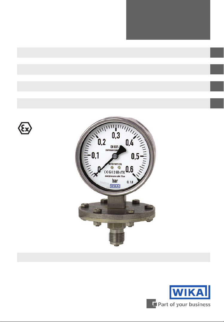
Pressure gauge model 4 per directive 94/9/EC (ATEX)
Druckmessgerät Typ 4 nach Richtlinie 94/9/EG (ATEX)
Manomètre type 4 selon directive 94/9/EG (ATEX)
Manómetro modelo 4 según la directiva 94/9/CE (ATEX)
II 2 GD c TX
GB
D
F
E
Model 432.50.100 per ATEX
Page 2

Operating instructions model 4 per ATEX Page 3-12
GB
Betriebsanleitung Typ 4 nach ATEX Seite 13-22
D
Mode d’emploi type 4 selon ATEX Page 23-32
F
Manual de instrucciones modelo 4 según ATEX Página 33-42
E
© 2010 WIKA Alexander Wiegand SE & Co. KG
All rights reserved. / Alle Rechte vorbehalten.
®
WIKA
is a registered trademark in various countries.
®
WIKA
ist eine geschützte Marke in verschiedenen Ländern.
Prior to starting any work, read the operating instructions!
Keep for later use!
Vor Beginn aller Arbeiten Betriebsanleitung lesen!
Zum späteren Gebrauch aufbewahren!
Lire le mode d'emploi avant de commencer toute opération !
A conserver pour une utilisation ultérieure !
¡Leer el manual de instrucciones antes de comenzar cualquier trabajo!
¡Guardar el manual para una eventual consulta posterior!
2
WIKA operating instructions pressure gauge model 4 per ATEX
2080276.04 12/2010 GB/D/F/E
Page 3
Contents
Contents
1. General information 4
2. Safety 5
3. Specications 8
4. Design and function 8
5. Transport, packaging and storage 8
6. Commissioning, operation 9
7. Maintenance and cleaning 11
8. Dismounting and disposal 11
Appendix 1:
Declarations of conformity can be found online at www.wika.de.
Declaration of conformity for models
43X.50, 43X.30 and 43X.X6
12
GB
2080276.04 12/2010 GB/D/F/E
WIKA operating instructions pressure gauge model 4 per ATEX 3
Page 4
1. General information
1. General information
The pressure gauge described in the operating instructions has been designed
and manufactured using state-of-the-art technology.
GB
All components are subject to stringent quality and environmental criteria
during production. Our management systems are certied to ISO 9001 and
ISO 14001.
These operating instructions contain important information on handling the
pressure gauge. Working safely requires that all safety instructions and work
instructions are observed.
Observe the relevant local accident prevention regulations and general safety
regulations for the pressure gauges range of use.
The operating instructions are part of the product and must be kept in the
immediate vicinity of the pressure gauge and readily accessible to skilled
personnel at any time.
Skilled personnel must have carefully read and understood the operating
instructions, prior to beginning any work.
The manufacturer‘s liability is void in the case of any damage caused by
using the product contrary to its intended use, non-compliance with these
operating instructions, assignment of insuciently qualied skilled personnel
or unauthorised modications to the pressure gauge.
The general terms and conditions contained in the sales documentation shall
apply.
Subject to technical modications.
Further information:
- Internet address: www.wika.de / www.wika.com
- Relevant data sheet: PM 04.03, PM 04.07
Explanation of symbols
WARNING!
... indicates a potentially dangerous situation that can result in
serious injury or death, if not avoided.
Information
… points out useful tips, recommendations and information for
ecient and trouble-free operation.
WARNING!
... indicates a potentially dangerous situation in a potentially
explosive atmosphere, resulting in serious injury or death, if not
avoided.
4
WIKA operating instructions pressure gauge model 4 per ATEX
2080276.04 12/2010 GB/D/F/E
Page 5
2. Safety
2. Safety
WARNING!
Before installation, commissioning and operation, ensure that
the appropriate pressure gauge has been selected in terms of
measuring range, design and specic measuring conditions.
Check the compatibility with the medium of the materials
subjected to pressure!
In order to guarantee the measuring accuracy and long-term
stability specied, the corresponding load limits must be
observed.
Non-observance can result in serious injury and/or damage to
the equipment.
Further important safety instructions can be found in the
individual chapters of these operating instructions.
2.1 Intended use
These pressure gauges are used for measuring pressure in hazardous areas of
industrial applications.
The pressure gauge has been designed and built solely for the intended use
described here, and may only be used accordingly.
The manufacturer shall not be liable for claims of any type based on operation
contrary to the intended use.
GB
2.2 Personnel qualication
WARNING!
Risk of injury should qualication be insucient!
Improper handling can result in considerable injury and damage
to equipment.
The activities described in these operating instructions
may only be carried out by skilled personnel who have the
qualications described below.
Skilled personnel
Skilled personnel are understood to be personnel who, based on their technical training, knowledge of measurement and control technology and on their
experience and knowledge of country-specic regulations, current standards and
directives, are capable of carrying out the work described and of independently
recognising potential hazards.
2080276.04 12/2010 GB/D/F/E
WIKA operating instructions pressure gauge model 4 per ATEX 5
Page 6
2. Safety
2.3 Safety instructions for pressure gauges per ATEX
WARNING!
Non-observance of these instructions and their contents may
GB
Specications
Operating temperatures
Ambient: -20 … +60 °C
with option silicone oil lling: -40 ... +60 °C
Medium: The permissible medium temperature does not only depend on the
Attention! With gaseous substances, the temperature may increase as a result
of compression warming. In these cases it may be necessary to throttle the rate
of change
of pressure or reduce the permissible medium temperature.
result in the loss of explosion protection.
WARNING!
It is imperative that the application conditions and safety require-
ments of the EC-type examination certicate are followed.
Pressure gauges must be earthed via the process connection!
instrument design, but also on the ignition temperature of the surrounding gases, vapours or dust. Both aspects have to be taken into account.
For permissible maximum medium temperatures see table 1.
Table 1: Permissible medium temperature
Temperature class of the ambient
explosive atmosphere
(ignition temperature)
T 6 (85 °C < T ≤ 100 °C) +70 °C
T 5 (100 °C < T ≤ 135 °C) +85 °C
T 4 (135 °C < T ≤ 200 °C) +100 °C or +120 °C
T 3 (200 °C < T ≤ 300 °C) +100 °C or +185 °C
T 2 (300 °C < T ≤ 450 °C) +100 °C or +200 °C
T 1 (T > 450 °C) +100 °C or +200 °C
1) The higher values apply only to special versions with higher permissible medium temperatures.
6
WIKA operating instructions pressure gauge model 4 per ATEX
Maximum permissible medium
temperature (in the measuring
system)
1)
1)
1)
1)
2080276.04 12/2010 GB/D/F/E
Page 7
2. Safety
2.4 Special hazards
WARNING!
Dangerous pressure media such as oxygen, acetylene, ammable gases or liquids, toxic gases or liquids as well as for refrigeration plants or compressors require attention above the standard
regulations. Here the specic safety codes or regulations must be
considered.
For additional important safety instructions see chapter "2.3 Safety instructions
for pressure gauges per ATEX".
WARNING!
Residual media in dismounted pressure gauges can result in a
risk to people, the environment and the system. Take sucient
precautionary measures.
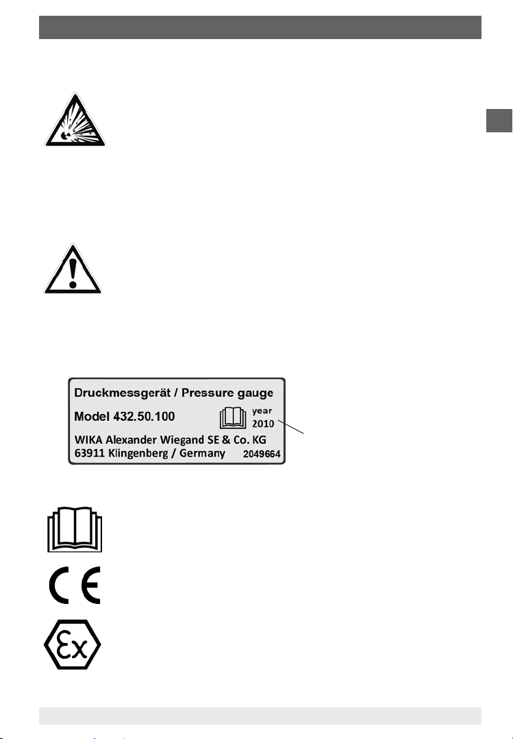
2.5 Labelling / safety marks
Product label
GB
Year of manufacture
Explanation of symbols
Before mounting and commissioning the pressure gauge, ensure
you read the operating instructions!
CE, Communauté Européenne
Instruments bearing this mark comply with the relevant European
directives.
ATEX European Explosion Protection Directive
(Atmosphère = AT, explosible = EX)
Instruments bearing this mark comply with the requirements of
the European Directive 94/9/EC (ATEX) on explosion protection.
2080276.04 12/2010 GB/D/F/E
WIKA operating instructions pressure gauge model 4 per ATEX 7
Page 8

3. Specications ... 5. Transport, packaging and storage
3. Specications
Pressure limitation
Model 43X.50/30: Steady: full scale value
GB
Fluctuating: 0.9 x full scale value
Short time: 5 x full scale value, however max. 40 bar
Model 43X.36/56: Steady: end value of measuring range
Fluctuating: 0.9 x end value of measuring range
Short time: 40, 100 or 400 bar
Temperature eect
When the temperature of the measuring system deviates from the reference
temperature (+20 °C): max. ±0.8 %/10 K of full scale value
IP Ingress protection
IP 54 per EN 60529 / IEC 529
(with liquid lling IP 65)
For further specications see WIKA data sheet PM 04.03, PM 04.07 and the
order documentation.
4. Design and function
Description
Nominal size 100 and 160 mm
The instruments measure the pressure by means of resilient diaphragm
measuring elements
The measuring characteristics are in accordance with the EN 837-3 standard
In addition, the enclosing and the pressurised components of models 43X.30
and 43X.36 also meet the requirements of EN 837-1, relating to safety pressure
gauges with a solid bae wall (code S3).
Scope of delivery
Cross-check scope of delivery with delivery note.
5. Transport, packaging and storage
5.1 Transport
Check pressure gauge for any damage that may have been caused by transport.
Obvious damage must be reported immediately.
8
WIKA operating instructions pressure gauge model 4 per ATEX
2080276.04 12/2010 GB/D/F/E
Page 9
6. Commissioning, operation
5.2 Packaging
Do not remove packaging until just before mounting.
Keep the packaging as it will provide optimum protection during transport (e.g.
change in installation site, sending for repair).
5.3 Storage
Permissible conditions at the place of storage:
Storage temperature: -20 ... +70 °C (optional: -40 … +70 °C)
6. Commissioning, operation
Mechanical connection
In accordance with the general technical regulations for pressure gauges (e.g.
EN 837-2 "Selection and installation recommendations for pressure gauges").
When screwing gauges in, the force required for this must not be applied through
the case, but rather through the spanner ats (using a suitable tool) provided for
this purpose on the square shaft of standard connections.
GB
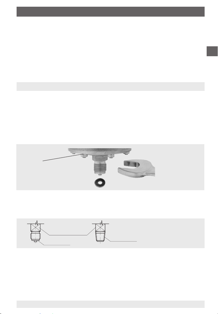
Flange connection 1)
Installation with
open-ended
1) The screw connection of the ange
must not be opened
spanner
Correct sealing of pressure gauge connections with parallel threads must be
made using suitable sealing rings, sealing washers or WIKA prole seals. The
sealing of tapered threads (e.g. NPT threads) is made by providing the thread
with additional sealing material such as, for example, PTFE tape (EN 837-2).
Spanner ats
Sealing face
Sealing in the
thread
The torque depends on the seal used. Connecting the gauge using a clamp
socket or a union nut is recommended, so that it is easier to orientate the gauge
correctly. When a blow-out device is tted to a pressure gauge, it must be
protected against being blocked by debris and dirt.
With safety pressure gauges (see dial symbol
k
) ensure that the free space
behind the blow-out back is at least 15 mm.
2080276.04 12/2010 GB/D/F/E
WIKA operating instructions pressure gauge model 4 per ATEX 9
Page 10

6. Commissioning, operation
Requirements for the installation point
If the line to the measuring instrument is not adequately stable, a measuring
instrument holder should be used for fastening. If vibrations cannot be avoided
by means of suitable installation, instruments with liquid lling should be used.
GB
The instruments should be protected against coarse dirt and wide uctuations in
ambient temperature.
Installation
Nominal position per EN 837-3 / 9.6.6 Figure 7: 90° ( ⊥ )
Process connection lower mount (LM)
In order to avoid any additional heating, the instruments must not be exposed
to direct solar irradiation while in operation!
With lled versions the vent valve at the top of the case must be opened before
commissioning!
Permissible ambient and operating temperatures
When mounting the pressure gauge it must be ensured that, taking into
consideration the inuence of convection and heat radiation, no deviation above
or below the permissible ambient and medium temperatures can occur. The
inuence of temperature on the indication accuracy must be observed.
Permissible vibration load at the installation site
The instruments should always be installed in locations free from vibration
If necessary, it is possible to isolate the instrument from the mounting point
by installing a exible connection line between the measuring point and the
pressure gauge and mounting the instrument on a suitable bracket.
If this is not possible, the following limit values must not be exceeded:
Dry gauges: Frequency range < 150 Hz
(Model 432) Acceleration < 0.7 g (7 m/s
2
)
Liquid-lled gauges: Frequency range < 150 Hz
(Model 433) Acceleration < 4 g (40 m/s
2
)
The liquid lling must be checked on a regular basis.
The liquid level must not drop below 75 % of the gauge diameter.
10
WIKA operating instructions pressure gauge model 4 per ATEX
2080276.04 12/2010 GB/D/F/E
Page 11
7. Maintenance and cleaning / 8. Dismounting and disposal
Commissioning
During the commissioning process pressure surges must be avoided at all costs.
Open the shut-o valves slowly.
7. Maintenance and cleaning
7.1 Maintenance
The instruments are maintenance-free.
The indicator should be checked once or twice every year.
For this the instrument must be disconnected from the process to check with a
pressure testing device.
Repairs must only be carried out by the manufacturer or appropriately qualied
skilled personnel.
7.2 Cleaning
CAUTION!
Clean the pressure gauge with a moist cloth.
Wash or clean the dismounted pressure gauge before return-
ing it, in order to protect persons and the environment from
exposure to residual media.
GB
8. Dismounting and disposal
WARNING!
Residual media in dismounted pressure gauges can result in a
risk to persons, the environment and equipment. Take sucient
precautionary measures.
8.1 Dismounting
Only disconnect the pressure gauge once the system has been depressurised!
8.2 Disposal
Incorrect disposal can put the environment at risk.
Dispose of instrument components and packaging materials in an environmen-
tally compatible way and in accordance with the country-specic waste disposal
regulations.
2080276.04 12/2010 GB/D/F/E
WIKA operating instructions pressure gauge model 4 per ATEX 11
Page 12
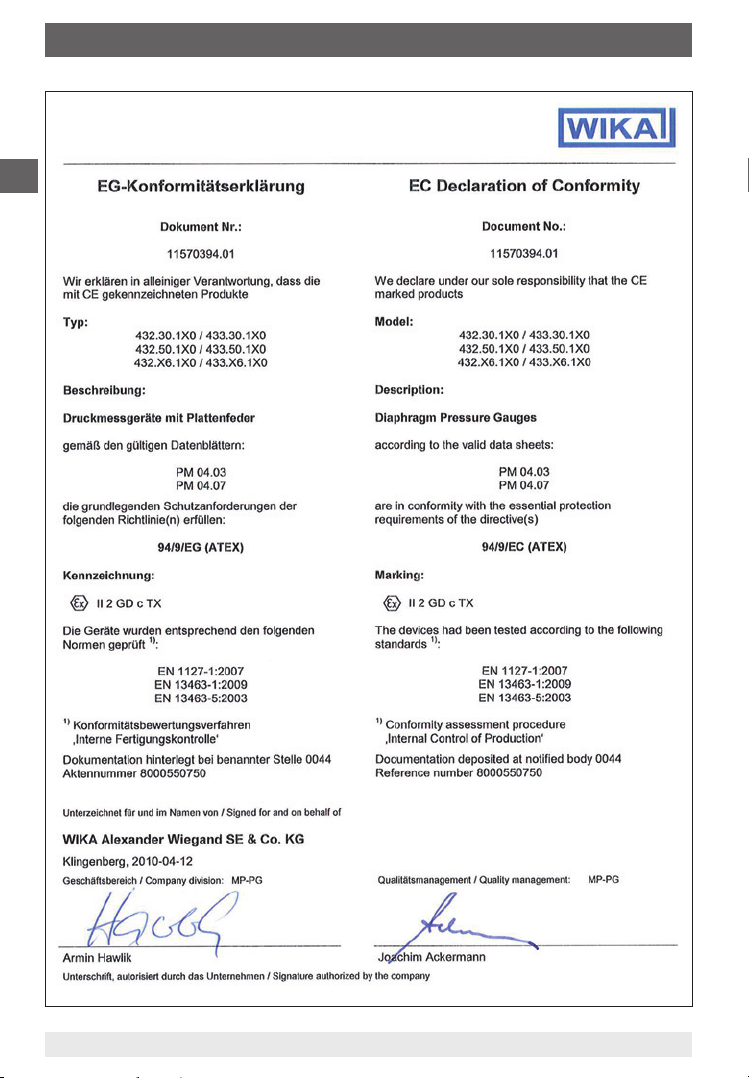
Appendix 1: Declaration of conformity
GB
12
WIKA operating instructions pressure gauge model 4 per ATEX
2080276.04 12/2010 GB/D/F/E
Page 13
Inhalt
Inhalt
1. Allgemeines 14
2. Sicherheit 15
3. Technische Daten 18
4. Aufbau und Funktion 18
5. Transport, Verpackung und Lagerung 18
6. Inbetriebnahme, Betrieb 19
7. Wartung und Reinigung 21
8. Demontage und Entsorgung 21
Anlage 1: Konformitätserklärung für Typen
43X.50, 43X.30 und 43X.X6
Konformitätserklärungen nden Sie online unter www.wika.de.
22
D
2080276.04 12/2010 GB/D/F/E
13WIKA Betriebsanleitung Druckmessgerät Typ 4 nach ATEX
Page 14
1. Allgemeines
1. Allgemeines
Das in der Betriebsanleitung beschriebene Druckmessgerät wird nach den
neuesten Erkenntnissen konstruiert und gefertigt.
Alle Komponenten unterliegen während der Fertigung strengen Qualitäts-
und Umweltkriterien. Unsere Managementsysteme sind nach ISO 9001 und
ISO 14001 zertiziert.
D
Diese Betriebsanleitung gibt wichtige Hinweise zum Umgang mit dem Druck-
messgerät. Voraussetzung für sicheres Arbeiten ist die Einhaltung aller
angegebenen Sicherheitshinweise und Handlungsanweisungen.
Die für den Einsatzbereich des Druckmessgerätes geltenden örtlichen Unfall-
verhütungsvorschriften und allgemeinen Sicherheitsbestimmungen einhalten.
Die Betriebsanleitung ist Produktbestandteil und muss in unmittelbarer Nähe
des Druckmessgerätes für das Fachpersonal jederzeit zugänglich aufbewahrt
werden.
Das Fachpersonal muss die Betriebsanleitung vor Beginn aller Arbeiten
sorgfältig durchgelesen und verstanden haben.
Die Haftung des Herstellers erlischt bei Schäden durch bestimmungswidrige
Verwendung, Nichtbeachten dieser Betriebsanleitung, Einsatz ungenügend
qualizierten Fachpersonals sowie eigenmächtiger Veränderung am Druck-
messgerät.
Es gelten die allgemeinen Geschäftsbedingungen in den Verkaufsunterlagen.
Technische Änderungen vorbehalten.
Weitere Informationen:
- Internet-Adresse: www.wika.de / www.wika.com
- zugehöriges Datenblatt: PM 04.03, PM 04.07
Symbolerklärung
WARNUNG!
… weist auf eine möglicherweise gefährliche Situation hin, die
zum Tod oder zu schweren Verletzungen führen kann, wenn sie
nicht gemieden wird.
Information
… hebt nützliche Tipps und Empfehlungen sowie Informationen
für einen ezienten und störungsfreien Betrieb hervor.
WARNUNG!
… weist auf eine möglicherweise gefährliche Situation im
explosionsgefährdeten Bereich hin, die zum Tod oder zu
schweren Verletzungen führt, wenn sie nicht gemieden wird.
WIKA Betriebsanleitung Druckmessgerät Typ 4 nach ATEX14
2080276.04 12/2010 GB/D/F/E
Page 15

2. Sicherheit
2. Sicherheit
WARNUNG!
Vor Montage, Inbetriebnahme und Betrieb sicherstellen, dass das
richtige Druckmessgerät hinsichtlich Messbereich, Ausführung
und spezischen Messbedingungen ausgewählt wurde.
Verträglichkeit der druckbelasteten Werkstoe mit dem Messsto
prüfen!
Die Belastungsgrenzen sind einzuhalten, um die Messgenauig-
keit und die Lebensdauer zu gewährleisten.
Bei Nichtbeachten können schwere Körperverletzungen und/oder
Sachschäden auftreten.
Weitere wichtige Sicherheitshinweise benden sich in den
einzelnen Kapiteln dieser Betriebsanleitung.
2.1 Bestimmungsgemäße Verwendung
Diese Druckmessgeräte dienen zum Messen von Druck bei industriellen Anwendungen in explosionsgefährdeten Bereichen.
Das Druckmessgerät ist ausschließlich für den hier beschriebenen bestimmungsgemäßen Verwendungszweck konzipiert und konstruiert und darf nur dementsprechend verwendet werden.
Ansprüche jeglicher Art aufgrund von nicht bestimmungsgemäßer Verwendung
sind ausgeschlossen.
D
2.2 Personalqualikation
WARNUNG!
Verletzungsgefahr bei unzureichender Qualikation!
Unsachgemäßer Umgang kann zu erheblichen Personen- und
Sachschäden führen.
Die in dieser Betriebsanleitung beschriebenen Tätigkeiten nur
durch Fachpersonal nachfolgend beschriebener Qualikation
durchführen lassen.
Fachpersonal
Das Fachpersonal ist aufgrund seiner fachlichen Ausbildung, seiner Kenntnisse
der Mess- und Regelungstechnik und seiner Erfahrungen sowie Kenntnis der
landesspezischen Vorschriften, geltenden Normen und Richtlinien in der Lage,
die beschriebenen Arbeiten auszuführen und mögliche Gefahren selbstständig
zu erkennen.
2080276.04 12/2010 GB/D/F/E
15WIKA Betriebsanleitung Druckmessgerät Typ 4 nach ATEX
Page 16

2. Sicherheit
2.3 Sicherheitshinweise für Druckmessgeräte nach ATEX
WARNUNG!
Die Nichtbeachtung dieser Inhalte und Anweisungen kann zum
Verlust des Explosionsschutzes führen.
D
WARNUNG!
Einsatzbedingungen und sicherheitstechnische Daten der
EG Baumusterprüfbescheinigung unbedingt beachten.
Druckmessgeräte über den Prozessanschluss erden!
Technische Daten
Zulässige Temperaturen
Umgebung: -20 … +60 °C
bei Option Silikonölfüllung: -40 ... +60 °C
Messsto: Die zulässige Messstotemperatur hängt außer von der Gerätebauart
auch von der Zündtemperatur der umgebenden Gase, Dämpfe bzw.
Stäube ab. Beide Aspekte sind zu berücksichtigen.
Maximal zulässige Grenzwerte siehe Tabelle 1.
Achtung! Bei gasförmigen Stoen kann sich die Temperatur durch Kompressi-
onswärme erhöhen. In solchen Fällen muss ggf. die Druckänderungsgeschwin-
digkeit gedrosselt bzw. die zulässige Messstotemperatur reduziert werden.
Tabelle 1: Zulässige Messstotemperatur
Temperaturklasse der umgebenden
zündfähigen Atmosphäre
Zulässige maximale Messsto-
temperatur (im Messsystem)
(Zündtemperatur)
T 6 (85 °C < T ≤ 100 °C) +70 °C
T 5 (100 °C < T ≤ 135 °C) +85 °C
T 4 (135 °C < T ≤ 200 °C) +100 °C bzw. +120 °C
T 3 (200 °C < T ≤ 300 °C) +100 °C bzw. +185 °C
T 2 (300 °C < T ≤ 450 °C) +100 °C bzw. +200 °C
T 1 (T > 450 °C) +100 °C bzw. +200 °C
1) Die höheren Werte gelten nur für Sonderausführungen mit höheren zulässigen Messstotemperaturen.
1)
1)
1)
1)
WIKA Betriebsanleitung Druckmessgerät Typ 4 nach ATEX16
2080276.04 12/2010 GB/D/F/E
Page 17

2. Sicherheit
2.4 Besondere Gefahren
WARNUNG!
Bei gefährlichen Messstoen wie z.B. Sauersto, Acetylen,
brennbaren oder giftigen Stoen, sowie bei Kälteanlagen,
Kompressoren etc. müssen über die gesamten allgemeinen Regeln hinaus die jeweils bestehenden einschlägigen
Vorschriften beachtet werden.
Weitere wichtige Sicherheitshinweise siehe Kapitel "2.3 Sicherheitshinweise für
Druckmessgeräte nach ATEX".
WARNUNG!
Messstoreste in ausgebauten Druckmessgeräten können zur
Gefährdung von Personen, Umwelt und Einrichtung führen.
Ausreichende Vorsichtsmaßnahmen ergreifen.
2.5 Beschilderung / Sicherheitskennzeichnungen
Typenschild
D
Symbolerklärung
Vor Montage und Inbetriebnahme des Druckmessgerätes
unbedingt die Betriebsanleitung lesen!
CE, Communauté Européenne
Geräte mit dieser Kennzeichnung stimmen überein mit den
zutreenden europäischen Richtlinien.
ATEX Europäische Explosionsschutz-Richtlinie
(Atmosphère = AT, explosible = EX)
Geräte mit dieser Kennzeichnung stimmen überein mit den Anforderungen der europäischen Richtlinie 94/9/EG (ATEX)
zum Explosionsschutz.
2080276.04 12/2010 GB/D/F/E
Herstellungsjahr
17WIKA Betriebsanleitung Druckmessgerät Typ 4 nach ATEX
Page 18

3. Technische Daten ... 5. Transport, Verpackung und Lagerung
3. Technische Daten
Druckbelastbarkeit
Typ 43X.50/30: Ruhebelastung: Skalenendwert
Wechselbelastung: 0,9 x Skalenendwert
kurzzeitig: 5 x Skalenendwert, jedoch max. 40 bar
D
Typ 43X.36/56: Ruhebelastung: Messbereichsendwert
Wechselbelastung: 0,9 x Messbereichsendwert
kurzzeitig: 40, 100 bzw. 400 bar
Temperatureinuss
Bei Abweichung von der Referenztemperatur am Messsystem (+20 °C):
max. ±0,8 %/10 K vom jeweiligen Skalenendwert
IP Schutzart
IP 54 nach EN 60529 / IEC 529
(mit Flüssigkeitsfüllung IP 65)
Weitere technische Daten siehe WIKA Datenblatt PM 04.03, PM 04.07 und
Bestellunterlagen.
4. Aufbau und Funktion
Beschreibung
Nenngröße 100 und 160 mm
Die Geräte erfassen den zu messenden Druck mit elastischen Plattenfeder-
Messgliedern
Die messtechnischen Eigenschaften entsprechen der Norm EN 837-3
Die umhüllenden und druckbeaufschlagten Bauteile der Typen 43X.30 und
43X.36 erfüllen außerdem die Anforderungen der EN 837-1 an Sicherheits-
druckmessgeräte mit bruchsicherer Trennwand (Kurzzeichen S3).
Lieferumfang
Lieferumfang mit dem Lieferschein abgleichen.
5. Transport, Verpackung und Lagerung
5.1 Transport
Druckmessgerät auf eventuell vorhandene Transportschäden untersuchen.
Oensichtliche Schäden unverzüglich mitteilen.
WIKA Betriebsanleitung Druckmessgerät Typ 4 nach ATEX18
2080276.04 12/2010 GB/D/F/E
Page 19

6. Inbetriebnahme, Betrieb
5.2 Verpackung
Verpackung erst unmittelbar vor der Montage entfernen.
Die Verpackung aufbewahren, denn diese bietet bei einem Transport einen
optimalen Schutz (z. B. wechselnder Einbauort, Reparatursendung).
5.3 Lagerung
Zulässige Bedingungen am Lagerort
Lagertemperatur: -20 ... +70 °C (optional: -40 … +70 °C)
6. Inbetriebnahme, Betrieb
Mechanischer Anschluss
Entsprechend den allgemeinen technischen Regeln für Druckmessgeräte
(z. B. EN 837-2 "Auswahl- und Einbauempfehlungen für Druckmessgeräte").
Beim Einschrauben der Geräte darf die zum Abdichten erforderliche Kraft nicht
über das Gehäuse aufgebracht werden, sondern mit geeignetem Werkzeug nur
über die dafür vorgesehenen Schlüsselächen am Vierkant des Anschlusszapfens.
D
Flanschverbindung
1)
Montage mit
Gabelschlüssel
1) Die Schraubverbindung des Flansches
darf nicht geönet werden
Zur Abdichtung der Druckmessgeräteanschlüsse mit zylindrischem Gewinde an
der Dichtäche
sind Flachdichtungen, Dichtlinsen oder WIKA-Proldichtungen
einzusetzen. Bei kegeligem Gewinde (z. B. NPT-Gewinde) erfolgt die Abdichtung
im Gewinde , mit zusätzlichen Dichtwerkstoen, wie z. B. PTFE-Band (EN 837-2).
Schlüsseläche
Dichtäche
Abdichtung im
Gewinde
Das Anzugsmoment ist von der eingesetzten Dichtung abhängig. Um das
Messgerät in die Stellung zu bringen, in der es sich am besten ablesen lässt, ist
ein Anschluss mit Spannmue oder Überwurfmutter zu empfehlen. Sofern ein
Druckmessgerät eine Ausblasvorrichtung besitzt, muss diese vor Blockierung
durch Geräteteile oder Schmutz geschützt sein.
Bei Sicherheitsdruckmessgeräten (zu erkennen am
k
) ist darauf zu achten, dass
der Freiraum hinter der ausblasbaren Rückwand mindestens 15 mm beträgt.
2080276.04 12/2010 GB/D/F/E
19WIKA Betriebsanleitung Druckmessgerät Typ 4 nach ATEX
Page 20

6. Inbetriebnahme, Betrieb
Anforderungen an die Einbaustelle
Ist die Leitung zum Messgerät für eine erschütterungsfreie Anbringung nicht
stabil genug, sollte die Befestigung mittels Messgerätehalterung erfolgen.
Können Erschütterungen nicht durch geeignete Installationen vermieden
werden, dann sollten Geräte mit Flüssigkeitsfüllung eingesetzt werden. Die
Geräte sind vor grober Verschmutzung und starken Schwankungen der
D
Umgebungstemperatur zu schützen.
Installation
Nennlage nach EN 837-3 / 9.6.6 Bild 7: 90° (
Prozessanschluss unten
Um zusätzliche Aufheizung zu vermeiden, dürfen die Geräte im Betrieb keiner
direkten Sonneneinstrahlung ausgesetzt werden!
Bei gefüllten Ausführungen muss vor Inbetriebnahme das Entlüftungsventil an
der Oberseite des Gehäuses geönet werden!
Zulässige Umgebungs- u. Betriebstemperaturen
Die Anbringung des Druckmessgerätes ist so auszuführen, dass die zulässigen
Umgebungs- und Messstotemperaturgrenzen, auch unter Berücksichtigung des
Einusses von Konvektion und Wärmestrahlung, weder unter- noch überschritten
werden. Der Temperatureinuss auf die Anzeigegenauigkeit ist zu beachten.
Zulässige Schwingungsbelastung am Einbauort
Die Geräte sollten grundsätzlich nur an Stellen ohne Schwingungsbelastung
eingebaut werden
Gegebenenfalls kann z. B. durch eine exible Verbindungsleitung von der
Messstelle zum Druckmessgerät und die Befestigung über eine Messgeräte-
halterung eine Entkopplung vom Einbauort erreicht werden.
⊥ )
Falls dies nicht möglich ist, dürfen folgende Grenzwerte nicht überschritten
werden:
Ungefüllte Geräte: Frequenzbereich < 150 Hz
(Typ 432) Beschleunigung < 0,7 g (7 m/s
2
)
Flüssigkeitsgefüllte Geräte: Frequenzbereich < 150 Hz
(Typ 433) Beschleunigung < 4 g (40 m/s
2
)
Die Flüssigkeitsfüllung ist regelmäßig zu überprüfen.
Der Flüssigkeitsspiegel darf nicht unter 75 % des Gerätedurchmessers fallen.
WIKA Betriebsanleitung Druckmessgerät Typ 4 nach ATEX20
2080276.04 12/2010 GB/D/F/E
Page 21

7. Wartung und Reinigung / 8. Demontage und Entsorgung
Inbetriebnahme
Bei Inbetriebnahme Druckstöße unbedingt vermeiden, Absperrventile langsam
önen.
7. Wartung und Reinigung
7.1 Wartung
Die Geräte sind wartungsfrei.
Eine Überprüfung der Anzeige sollte etwa 1 bis 2 mal pro Jahr erfolgen.
Dazu ist das Gerät vom Prozess zu trennen und mit einer Druckprüfvorrichtung
zu kontrollieren.
Reparaturen sind ausschließlich vom Hersteller oder entsprechend quali-
ziertem Fachpersonal durchzuführen.
7.2 Reinigung
VORSICHT!
Das Druckmessgerät mit einem feuchten Tuch reinigen.
Ausgebautes Druckmessgerät vor der Rücksendung spülen
bzw. säubern, um Personen und Umwelt vor Gefährdung durch
anhaftende Messstoreste zu schützen.
D
8. Demontage und Entsorgung
WARNUNG!
Messstoreste in ausgebauten Druckmessgeräten können
zur Gefährdung von Personen, Umwelt und Einrichtung führen.
Ausreichende Vorsichtsmaßnahmen ergreifen.
8.1 Demontage
Druckmessgerät nur im drucklosen Zustand demontieren!
8.2 Entsorgung
Durch falsche Entsorgung können Gefahren für die Umwelt entstehen.
Gerätekomponenten und Verpackungsmaterialien entsprechend den landes-
spezischen Abfallbehandlungs- und Entsorgungsvorschriften umweltgerecht
entsorgen.
2080276.04 12/2010 GB/D/F/E
21WIKA Betriebsanleitung Druckmessgerät Typ 4 nach ATEX
Page 22

Anlage 1: Konformitätserklärung
D
WIKA Betriebsanleitung Druckmessgerät Typ 4 nach ATEX22
2080276.04 12/2010 GB/D/F/E
Page 23

Sommaire
Sommaire
1. Généralités 24
2. Sécurité 25
3. Caractéristiques techniques 28
4. Conception et fonction 28
5. Transport, emballage et stockage 28
6. Mise en service, exploitation 29
7. Entretien et nettoyage 31
8. Démontage et mise au rebut 31
Annexe 1: Déclaration de conformité des types
43X.50, 43X.30 et 43X.X6
Déclarations de conformité se trouve sur www.wika.fr.
32
F
2080276.04 12/2010 GB/D/F/E
WIKA mode d'emploi manomètre type 4 selon ATEX 23
Page 24

1. Généralités
1. Généralités
Le manomètre décrit dans le présent mode d'emploi est conçu et fabriqué
selon les dernières technologies en vigueur et tous les composants sont
soumis à des critères de qualité et d'environnement stricts durant la fabrication.
Nos systèmes de gestion sont certiés selon ISO 9001 et ISO 14001.
Ce mode d'emploi donne des indications importantes concernant l'utilisation
du manomètre. Il est possible de travailler en toute sécurité avec ce produit en
respectant toutes les consignes de sécurité et d'utilisation.
F
Respecter les prescriptions locales de prévention contre les accidents et les
prescriptions générales de sécurité en vigueur pour le domaine d'application
du manomètre.
Le mode d'emploi fait partie de l'appareil et doit être conservé à proximité
immédiate du manomètre et accessible à tout moment pour le personnel qualié.
Le personnel qualié doit, avant de commencer toute opération, avoir lu
soigneusement et compris le mode d’emploi.
La responsabilité du fabricant n'est pas engagée en cas de dommages provo-
qués par une utilisation non conforme à l'usage prévu, de non respect de ce
mode d'emploi, d'utilisation de personnel peu qualié de même qu'en cas de
modications du manomètre eectuées par l'utilisateur.
Les conditions générales de vente mentionnées dans les documents de vente
s'appliquent.
Sous réserve de modications techniques.
Pour obtenir d'autres informations:
- Consulter notre site Internet : www.wika.de / www.wika.com
- Fiche technique correspondante : PM 04.03, PM 04.07
Explication des symboles
AVERTISSEMENT !
… indique une situation présentant des risques susceptibles
de provoquer la mort ou des blessures graves si elle n'est pas
évitée.
Information
… met en exergue les conseils et recommandations utiles de
même que les informations permettant d'assurer un fonctionne-
ment ecace et normal.
AVERTISSEMENT !
… indique une situation en zone explosive présentant des risques
susceptibles de provoquer la mort ou des blessures graves si elle
n'est pas évitée.
WIKA mode d'emploi manomètre type 4 selon ATEX24
2080276.04 12/2010 GB/D/F/E
Page 25

2. Sécurité
2. Sécurité
AVERTISSEMENT !
Avant le montage, la mise en service et le fonctionnement,
s‘assurer que le manomètre a été choisi de façon adéquate, en
ce qui concerne la plage de mesure, la version et les conditions
de mesure spéciques.
Vérier si les matériaux soumis à la pression sont compatibles
avec le uide de mesure !
Les limites de surpression admissible sont à respecter an
d'assurer la précision et la durée de vie.
Le non-respect de cette consigne peut entraîner des blessures
corporelles et/ou des dégâts matériels graves.
Vous trouverez d'autres consignes de sécurité dans les sections
individuelles du présent mode d'emploi.
2.1 Utilisation conforme à l'usage prévu
Ces manomètres servent à mesurer la pression pour les applications industrielles
en zone explosive.
Le manomètre est conçu et construit exclusivement pour une utilisation conforme
à l'usage prévu décrit ici et ne doit être utilisé qu'en conséquence.
Aucune réclamation ne peut être recevable en cas d‘utilisation non conforme à
l‘usage prévu.
F
2.2 Qualication du personnel
AVERTISSEMENT !
Danger de blessure en cas de qualication insusante !
Une utilisation non conforme peut entraîner d'importants
dommages corporels et matériels.
Les opérations décrites dans ce mode d‘emploi ne doivent
être eectuées que par un personnel ayant la qualication
décrite ci-après.
Personnel qualié
Le personnel qualié est, en raison de sa formation spécialisée, de ses connaissances dans le domaine de la technique de mesure et de régulation et de ses
expériences de même que de sa connaissance des prescriptions nationales des
normes et directives en vigueur, en mesure d'eectuer les travaux décrits et de
reconnaître automatiquement les dangers potentiels.
2080276.04 12/2010 GB/D/F/E
WIKA mode d'emploi manomètre type 4 selon ATEX 25
Page 26

2. Sécurité
2.3 Consignes de sécurité pour les manomètres selon ATEX
AVERTISSEMENT !
Le non respect de ces instructions et de leurs contenus peut
entraîner une perte de la protection contre les explosions.
AVERTISSEMENT !
Respecter impérativement les conditions d‘utilisation et les
caractéristiques techniques de sécurité de l‘attestation d‘examen
F
Caractéristiques techniques
Températures admissibles
Ambiante: -20 … +60 °C
avec option remplissage d'huile de silicone: -40 ... +60 °C
Fluide: La température de uide admissible dépend, en plus de la conception de
de type CE.
Mettre à la terre les manomètres à l‘aide du branchement de
process !
l‘appareil, également de la température d‘inammation du gaz, des
vapeurs ou des poussières de l‘environnement. Ces deux paramètres
sont à prendre en considération.
Voir le tableau 1 pour les limites de température admissibles.
Attention! Pour les uides gazeux la température peut s‘élever par le biais d‘une
température de compression. Dans ces cas il faut, soit limiter la vitesse d‘éléva-
tion de la pression, soit réduire la température de uide admissible.
Tableau 1: Température de uide admissible
Classe de température de l‘atmosphère
environnante (température
d‘inammation)
T 6 (85 °C < T ≤ 100 °C) +70 °C
T 5 (100 °C < T ≤ 135 °C) +85 °C
T 4 (135 °C < T ≤ 200 °C) +100 °C ou +120 °C
T 3 (200 °C < T ≤ 300 °C) +100 °C ou +185 °C
T 2 (300 °C < T ≤ 450 °C) +100 °C ou +200 °C
T 1 (T > 450 °C) +100 °C ou +200 °C
1) Les valeurs plus élevées ne sont valables que pour les exécutions spéciales avec des températures de uide
admissibles supérieures.
WIKA mode d'emploi manomètre type 4 selon ATEX26
Température maximale
autorisée du uide (dans le
système de mesure)
1)
1)
1)
1)
2080276.04 12/2010 GB/D/F/E
Page 27

2. Sécurité
2.4 Dangers particuliers
AVERTISSEMENT !
Pour les uides dangereux comme par exemple l'oxygène,
l'acétylène les matiéres combustibles ou nocives ainsi que pour
les systèmes frigoriques et les compresseurs il faut en plus
des règles techniques courántes tenir compte des prescriptions
spéciques à ces mesures.
Autres consignes de sécurité importantes voir chapitre "2.3 Consignes de
sécurité pour les manomètres selon ATEX".
AVERTISSEMENT !
Les restes de uides se trouvant dans des manomètres
démontés peuvent mettre en danger les personnes, l‘environnement ainsi que l‘installation. Prendre des mesures de sécurité
susantes.
2.5 Etiquetage / Marquages de sécurité
Plaque signalétique
F
Année de fabrication
Explication des symboles
Lire impérativement le mode d‘emploi avant le montage et la mise
en service de manomètre !
CE, Communauté Européenne
Les appareils avec ce marquage sont conformes aux directives
européennes pertinentes.
ATEX Directive européenne sur les appareils destinés à être
utilisés en atmosphère explosible
(Atmosphère = AT, explosible = EX)
Les appareils avec ce marquage sont conformes aux exigences
de la directive européenne 94/9/CE (ATEX) sur la protection
contre les explosions.
2080276.04 12/2010 GB/D/F/E
WIKA mode d'emploi manomètre type 4 selon ATEX 27
Page 28

3. Caractéristiques techniques ... 5. Transport, emballage ...
3. Caractéristiques techniques
Limitations en pression
Type 43X.50/30: Charge statique: n d’échelle
Charge dynamique: 0,9 x n d’échelle
Momentanément:: 5 x n d‘échelle, mais 40 bar maxi
Type 43X.36/56: Charge statique: n d‘échelle de mesure
Charge dynamique: 90 % n d‘échelle de mesure
temporaire: 40, 100 ou 400 bar
F
Inuence de la température
En cas de divergence de la température de référence (+20 °C)
sur l’organe moteur: max. ±0,8 %/10 K de la valeur de n d’échelle
IP Indice de protection
IP 54 selon EN 60529 / IEC 529
(avec bain amortisseur IP 65)
Pour les autres caractéristiques techniques, voir che technique WIKA PM 04.03,
PM 04.07 et documents de commande.
4. Conception et fonction
Description
Diamètres 100 et 160 mm
Les appareils mesurent la pression par le biais d’un membrane manométrique
à déformation élastique
Les caractéristiques techniques de mesure correspondent aux norme EN 837-3
Le boîtier et la lunette ainsi que les pièces sous pression des types 43X.30 et
43X.36 satisfont également aux exigences de la norme EN 837-1 relative aux
manomètres de sécurité dotés d‘une cloison de sécurité incassable (abrévia-
tion S3).
Volume de livraison
Comparer le détail de la livraison avec le bordereau de livraison.
5. Transport, emballage et stockage
5.1 Transport
Vérier s‘il existe des dégâts sur l‘appareil liés au transport. Communiquer
immédiatement les dégâts constatés.
WIKA mode d'emploi manomètre type 4 selon ATEX28
2080276.04 12/2010 GB/D/F/E
Page 29

6. Mise en service, exploitation
5.2 Emballage
N'enlever l'emballage qu'avant le montage.
Conserver l‘emballage, celui-ci ore, lors d‘un transport, une protection optimale
(par ex. changement de lieu d‘utilisation, renvoi pour réparation).
5.3 Stockage
Conditions admissibles sur le lieu de stockage
Température de stockage: -20 ... +70 °C (en option: -40 … +70 °C)
6. Mise en service, exploitation
Raccordement mécanique
Conformément aux règles techniques générales pour les manomètres (par
exemple EN 837-2 "Recommandations sur le choix et l‘installation des
manomètres").
Lors du vissage des instruments, la force nécessaire ne doit pas être appliquée sur
le boîtier et prise câblée mais seulement sur les clefs plates prévues avec un outil
approprié.
Raccord à bride 1)
1) Le raccord à vis de la bride
ne doit pas être ouvert
Pour assurer l’étanchéité du raccord avec letage cylindrique du manomètre sur
la surface d‘étanchéité
il faut utiliser des joints plats, des joints forme lentille ou
les joints à écrasement WIKA. Pour les letages coniques (par exemple letage
NPT) l‘étanchéité sur le letage
s
e fait en utilisant en plus un matériau d‘étan-
chéité comme par exemple la bande PTFE (selon EN 837-2).
Clef plate
Surface d‘étanchéité
Etanchéité
sur letage
Le couple de serrage dépend du joint utilisé. An de positionner l‘appareil de
mesure de façon à ce qu‘il soit facilement lisible, il est recommandé d‘utiliser un
manchon de serrage ou un écrou-chapeau. Au cas où un manomètre est équipé
d‘une paroi arrière éjectable, celle-ci doit être protégée contre un blocage par des
pièces d‘appareil et contre la crasse.
Pour les manomètres en exécution de sécurité (reconnaissables au symbole
sur le cadran), il faut faire attention à ce que l‘espace libre à l‘arrière de l‘appareil
soit au minimum de 15 mm.
2080276.04 12/2010 GB/D/F/E
WIKA mode d'emploi manomètre type 4 selon ATEX 29
Montage avec
clé à fourche
k
F
Page 30

6. Mise en service, exploitation
Exigences particulières sur le point de montage
Si la conduite à l‘appareil de mesure n‘est pas susamment stable pour un
montage sans vibrations il faut prévoir la xation par l‘intermédiaire d‘un support
d‘appareil de mesure (et éventuellement par un capillaire exible). S‘il n‘est pas
possible de supprimer les vibrations par un montage approprié, il faut utiliser des
manomètres à remplissage de liquide. Les instruments doivent être protégés contre
un encrassement important et contre les uctuations de la température ambiante.
Installation
F
Position de base selon EN 837-3 / 9.6.6. image 7:: 90° ( ⊥ )
Raccord process vertical
Les instruments ne doivent pas être exposés directement aux rayons solaires
en cours d’utilisation pour ne pas provoquer d’échauement additionnel !
Pour les versions remplies de liquide, il faut, avant la mise en service, ouvrir la
soupape d'évacuation (pour
Températures ambiantes et de service autorisées
Le montage du manomètre est à réaliser de façon que la température de service
autorisée (ambiante et uide à mesurer), même sous l‘inuence de la chaleur
de convection et de radiation, ne doit pas être dépassée en augmentation ou en
diminution. Il faut prendre en considération l‘inuence de la température pour la
précision de la pression indiquée.
Contrainte de vibration admissible sur le point de montage
Les appareils ne devraient en principe être installés que sur des applications
exemptes de vibrations
Le cas échéant, on peut atteindre un isolement du point de mesure en utilisant
une liaison exible au manomètre et en le xant à l’aide d’un support mural.
Dans le cas où cela n‘est pas possible, les valeurs suivantes ne doivent pas
être dépassées:
Appareils sans remplissage : Plage de fréquence < 150 Hz
(Type 432) Accélération < 0,7 g (7 m/s
2
)
Appareils avec remplissage : Plage de fréquence < 150 Hz
(Type 433) Accélération < 4 g (40 m/s
2
)
Le liquide de remplissage doit être contrôlé régulièrement.
Le niveau de remplissage de liquide ne doit pas descendre en-dessous de 75 %
du diamètre du boîtier.
WIKA mode d'emploi manomètre type 4 selon ATEX30
2080276.04 12/2010 GB/D/F/E
Page 31

7. Entretien et nettoyage / 8. Démontage et mise au rebut
Mise en service
Lors de la mise en service il faut absolument éviter les coups de bélier. Ouvrir
lentement les robinets d'isolement.
7. Entretien et nettoyage
7.1 Entretien
Les instruments ne requièrent aucun entretien.
Un contrôle de l’achage et des fonctions de commande est recommandé 1 à
2 fois/an.
Pour le contrôle de l’achage et des fonctions de commande, il faut isoler
l’appareil du process et le contrôler avec un dispositif de contrôle de pression.
Toute réparation doit être exclusivement conée au fabricant ou au personnel
qualié correspondant.
7.2 Nettoyage
ATTENTION !
Nettoyer le manomètre avec un chion humide.
Laver ou nettoyer le manomètre démonté avant de le retourner
an de protéger les collaborateurs et l‘environnement contre le
danger lié aux restes de uides adhérents.
F
8. Démontage et mise au rebut
AVERTISSEMENT !
Les restes de uides se trouvant dans des manomètres
démontés peuvent mettre en danger les personnes,
l'environnement ainsi que l'installation. Prendre des mesures de
sécurité susantes.
8.1 Démontage
Démonter le manomètre uniquement qu‘en état exempt de pression !
8.2 Mise au rebut
Une mise au rebut inadéquate peut entraîner des dangers pour l‘environnement.
Éliminer les composants des appareils et les matériaux d‘emballage
conformément aux prescriptions nationales pour le traitement et l‘élimination des
déchets et aux lois de protection de l‘environnement en vigueur.
2080276.04 12/2010 GB/D/F/E
WIKA mode d'emploi manomètre type 4 selon ATEX 31
Page 32

Annexe 1: Déclaration de conformité
F
WIKA mode d'emploi manomètre type 4 selon ATEX32
2080276.04 12/2010 GB/D/F/E
Page 33

Contenido
Contenido
1. Información general 34
2. Seguridad 35
3. Datos técnicos 38
4. Diseño y función 38
5. Transporte, embalaje y almacenamiento 38
6. Puesta en servicio, funcionamiento 39
7. Mantenimiento y limpieza 41
8. Desmontaje y eliminación 41
Anexo 1: Declaración de conformidad para los modelos
43X.50, 43X.30 y 43X.X6
Declaraciones de conformidad puede encontrar en www.wika.es.
42
E
2080276.04 12/2010 GB/D/F/E
WIKA manual de instrucciones para manómetro modelo 4 según ATEX 33
Page 34

1. Información general
1. Información general
El manómetro descrito en el manual de instrucciones está construido y
fabricado según los conocimientos actuales. Todos los componentes están
sujetos a criterios rígidos de calidad y medio ambiente durante la producción.
Nuestros sistemas de gestión están certicados según ISO 9001 e ISO 14001.
Este manual de instrucciones proporciona indicaciones importantes acerca del
manejo del manómetro. Para un trabajo seguro, es imprescindible cumplir con
todas las instrucciones de seguridad y manejo indicadas.
Cumplir siempre las normativas sobre la prevención de accidentes y las
normas de seguridad en vigor en el lugar de utilización del manómetro.
El manual de instrucciones es una parte integrante del manómetro y debe
E
guardarse en la proximidad del mismo para que el personal especializado
pueda consultarlo en cualquier momento.
El personal especializado debe haber leído y entendido el manual de
instrucciones antes de comenzar cualquier trabajo.
El fabricante queda exento de cualquier responsabilidad en caso de daños
causados por un uso no conforme a la nalidad prevista, la inobservancia del
presente manual de instrucciones, un manejo por personal insucientemente
cualicado así como una modicación no autorizada del manómetro.
Se aplican las condiciones generales de venta incluidas en la documentación
de venta.
Modicaciones técnicas reservadas.
Para obtener más informaciones consultar:
- Página web: www.wika.es
- Hoja técnica correspondiente: PM 04.03, PM 04.07
Explicación de símbolos
¡ADVERTENCIA!
... indica una situación probablemente peligrosa que pueda
causar la muerte o lesiones graves si no se evita.
Información
... marca consejos y recomendaciones útiles así como informa-
ciones para una utilización ecaz y libre de fallos.
¡ADVERTENCIA!
… indica una situación probablemente peligrosa en una
atmósfera potencialmente explosiva que causa la muerte o
lesiones graves si no se evita.
WIKA manual de instrucciones para manómetro modelo 4 según ATEX34
2080276.04 12/2010 GB/D/F/E
Page 35

2. Seguridad
2. Seguridad
¡ADVERTENCIA!
Antes del montaje, la puesta en servicio y el funcionamiento
asegurarse de que se haya seleccionado el manómetro
adecuado con respecto a rango de medida, versión y
condiciones de medición especícas.
¡Asegúrese de que los productos bajo presión sean aptos para el
material de medición!
Para garantizar la precisión de medición y la durabilidad del
instrumento, se deberán respetar los límites de carga.
Riesgo de lesiones graves y/o daños materiales en caso de
inobservancia.
Los capítulos de este manual de instrucciones contienen otras
importantes indicaciones de seguridad.
2.1 Uso conforme a lo previsto
Esos manómetros sirven para medir la presión en aplicaciones industriales en
atmósferas potencialmente explosivas.
El manómetro ha sido diseñado y construido únicamente para la nalidad aquí
descrita y debe utilizarse en conformidad a la misma.
No se admite ninguna reclamación debido a un manejo no adecuado.
E
2.2 Cualicación del personal
¡ADVERTENCIA!
¡Riesgo de lesiones debido a una insuciente cualicación!
Un manejo no adecuado puede causar considerables daños
personales y materiales.
Las actividades descritas en este manual de instrucciones
deben realizarse únicamente por personal especializado con
la consiguiente cualicación.
Personal especializado
Debido a su formación profesional, a sus conocimientos de la técnica de
regulación y medición así como a su experiencia y su conocimiento de las
normativas, normas y directivas vigentes en el país de utilización el personal
especializado es capaz de ejecutar los trabajos descritos y reconocer posibles
peligros por sí solo.
2080276.04 12/2010 GB/D/F/E
WIKA manual de instrucciones para manómetro modelo 4 según ATEX 35
Page 36

2. Seguridad
2.3 Instrucciones de seguridad para manómetros según ATEX
¡ADVERTENCIA!
La inobservancia del contenido y de las instrucciones puede
originar la pérdida de la protección contra explosiones.
¡ADVERTENCIA!
Es imprescindible observar las condiciones de uso y los datos de
seguridad del certicado CE de tipo.
¡Poner a tierra los manómetros a través de la conexión al
E
Datos técnicos
Temperaturas admisibles
Ambiente: -20 … +60 °C
con opción relleno de aceite silicona: -40 ... +60 °C
Medio: La temperatura del medio admisible depende del tipo de construcción del
¡Atención! La temperatura puede aumentar con medios gaseosos a causa del
calor de compresión. En estos casos, hay que disminuir la velocidad de cambio
de presión o reducir la temperatura admisible del medio si fuera necesario.
proceso!
instrumento y de la temperatura de inamación de los gases, vapores
o polvos en el ambiente. Hay que respetar ambos aspectos. Para los
valores límite máx. admisibles, véase la tabla 1.
Tabla 1: Temperatura admisible del medio
Clase de temperatura de la atmósfera ambiente inamable
Temperatura máx. admisible del
medio (en el sistema de medición)
(temperatura de inamación)
T 6 (85 °C < T ≤ 100 °C) +70 °C
T 5 (100 °C < T ≤ 135 °C) +85 °C
T 4 (135 °C < T ≤ 200 °C) +100 °C ó +120 °C
T 3 (200 °C < T ≤ 300 °C) +100 °C ó +185 °C
T 2 (300 °C < T ≤ 450 °C) +100 °C ó +200 °C
T 1 (T > 450 °C) +100 °C ó +200 °C
1) Los valores superiores son válidos únicamente para versiones especiales con temperaturas admisibles superiores.
WIKA manual de instrucciones para manómetro modelo 4 según ATEX36
1)
1)
1)
1)
2080276.04 12/2010 GB/D/F/E
Page 37

2. Seguridad
2.4 Riesgos especícos
¡ADVERTENCIA!
En los casos de sustancias de medición peligrosas (por ej.:
oxígeno, acetileno, sustancias inamables o tóxicas), así como
en instalaciones de refrigeración, compresores, etc., deberán
respetarse tanto las normas generales, como las especicaciones referentes a cada una de estas sustancias.
Consultar el capítulo "2.3 Instrucciones de seguridad para manómetros según
ATEX" para más instrucciones de seguridad importantes.
¡ADVERTENCIA!
Restos de medios en manómetros desmontados pueden crear
riesgos para personas, medio ambiente e instalación. Tomar
adecuadas medidas de precaución.
2.5 Rótulos / Marcados de seguridad
Placa indicadora de modelo
E
Año de fabricación
Explicación de símbolos
¡Es absolutamente necesario leer el manual de instrucciones
antes del montaje y la puesta en servicio del manómetro!
CE, Communauté Européenne
Los instrumentos con este marcaje cumplen las directivas
europeas aplicables.
ATEX Directiva europea para garantizar la seguridad frente
a las explosiones
(Atmosphère = AT, explosible = EX)
Los instrumentos con este marcado están conformes a las
exigencias de la directiva europea 94/9/CE (ATEX) relativa a la
prevención de explosiones.
2080276.04 12/2010 GB/D/F/E
WIKA manual de instrucciones para manómetro modelo 4 según ATEX 37
Page 38

3. Datos técnicos ... 5. Transporte, embalaje y almacenamiento
3. Datos técnicos
Presión admisible
Modelo 43X.50/30: carga estática: valor nal de escala
Carga dinámica: 0,9 x valor nal de escala
carga puntual: 5 x valor nal de escala, pero máx. 40 bar
Modelo 43X.36/56: carga estática:: valor nal del rango de medida
carga dinámica: 0,9 x valor nal del rango de medida
a corto plazo: 40, 100 ó 400 bar
Inuencia de temperatura
En caso de desviación de la temperatura de referencia en el sistema de medición
E
(+20°C): máx. ±0,8 %/10 K del valor nal de escala correspondiente
Tipo de protección IP
IP 54 según EN 60529 / IEC 529
(con líquido de llenado IP 65)
Para más datos técnicos véase la hoja técnica de WIKA PM 04.03, PM 04.07 y la
documentación de pedido.
4. Diseño y función
Descripción
Diámetro nominal 100 y 160 mm
Los instrumentos captan la presión a medir mediante membranas elásticas
Las características técnicas de medición corresponden a la norma EN 837-3
Los componentes envolventes y sometidos a presión de los modelos 43X.30 y
43X.36 cumplen además los requisitos de la normativa EN 837-1 en referencia
a manómetros de seguridad con solidfront (abreviación S3).
Volumen de suministro
Comparar mediante el albarán si se han entregado todas las piezas.
5. Transporte, embalaje y almacenamiento
5.1 Transporte
Comprobar si el manómetro presenta eventuales daños causados en el
transporte. Noticar daños obvios de forma inmediata.
WIKA manual de instrucciones para manómetro modelo 4 según ATEX38
2080276.04 12/2010 GB/D/F/E
Page 39

6. Puesta en servicio, funcionamiento
5.2 Embalaje
No quitar el embalaje hasta justo antes del montaje. Guardar el embalaje ya que
es la protección ideal durante el transporte (por ejemplo si el lugar de instalación
cambia o si se envía el instrumento para posibles reparaciones).
5.3 Almacenamiento
Condiciones admisibles en el lugar de almacenamiento
Temperatura de almacenamiento: -20 ... +70 °C (opcional: -40 … +70 °C)
6. Puesta en servicio, funcionamiento
La conexión mecánica
Conforme a las reglas técnicas generales para manómetros (por ejemplo EN
837-2 Recomendaciones relativas a la selección y montaje de manómetros).
Para atornillar el aparato, se debe utilizar la fuerza mediante el uso de
herramientas adecuadas sobre las supercies planas de ajuste -previstas para
este n-. Nunca sobre la caja.
Conexión bridada
1)
Montaje
mediante
1) No abrir la conexión roscada de la brida
llave de boca
Para el cierre de las conexiones de los manómetros con roscas cilíndricas en la
supercie de cierre se debe instalar juntas planas, arandelas o juntas perladas
WIKA. Para roscas cónicas (por ejemplo, roscas NPT) se realiza el cierre en la
rosca
con material de cierre complementario, como por ejemplo, cinta PTFE (EN 837-2).
Supercie plana
de ajuste
Supercie de cierre
Junta en
la rosca
El momento de arranque depende del tipo de cierre utilizado. Para poner el
manómetro en la posición que proporcionará la mejor lectura, se recomienda una
conexión con un manguito tensor o tuerca tapón. Si un manómetro está dotado
de un dispositivo de ventilación es necesario protegerlo contra blocaje por piezas
de aparatos o suciedad.
En caso de manómetros de seguridad (reconocibles por la inscripción
k
) se
debe vigilar que el espacio detrás de la pared trasera de escape es de 15 mm
como mínimo.
2080276.04 12/2010 GB/D/F/E
WIKA manual de instrucciones para manómetro modelo 4 según ATEX 39
E
Page 40

6. Puesta en servicio, funcionamiento
Requerimientos en el lugar de instalación
Si el tubo que conecta al aparato de medición no fuera sucientemente estable
para asegurar una conexión exenta de vibraciones, se debería efectuar la
sujeción mediante un soporte de aparatos de medición. En el caso de no poder
evitar las vibraciones mediante las instalaciones apropiadas, deben instalarse
instrumentos con relleno de líquido. Los instrumentos deben protegerse contra
contaminación y fuertes oscilaciones de la temperatura ambiente.
Instalación
Posición nominal según EN 837-3 / 9.6.6 ilustr 7: 90° ( ⊥ )
Conexión a proceso inferior
E
¡No exponer los instrumentos a la radiación solar directa durante el
funcionamiento para evitar un calentamiento adicional!
¡En versiones con relleno hay que abrir la válvula de ventilación en el lado
superior de la caja!
Las temperaturas ambiente y de funcionamiento permitidas
Se debe efectuar la instalación del manómetro de tal forma, que no se excedan
los límites de la temperatura ambiente ni la del material de medición, incluyendo
la inuencia de convección y la radiación térmica. Debe tenerse en cuenta la
inuencia de la temperatura en la precisión de indicación.
Oscilación admisible en el lugar de instalación
Instalar los instrumentos sólo en lugares sin vibraciones.
Si es necesario, el desacoplamiento del lugar de instalación puede
conseguirse por ejemplo mediante una línea de conexión exible del punto de
medición al manómetro y mediante jación por medio de un soporte para el
manómetro.
Si esto no es posible, no se debe sobrepasar en ningun caso los siguientes
valores límites:
Instrumentos vacíos: gama de frecuencias < 150 Hz
(Modelo 432) aceleración < 0,7 g (7 m/s
2
)
Instrumentos llenados de líquido: gama de frecuencia < 150 Hz
(Modelo 433) aceleración < 4 g (40 m/s
2
)
Comprobar el llenado de líquido a intervalos regulares.
El nivel de líquido no debe caer debajo del 75 % del diámetro del instrumento.
WIKA manual de instrucciones para manómetro modelo 4 según ATEX40
2080276.04 12/2010 GB/D/F/E
Page 41

7. Mantenimiento y limpieza / 8. Desmontaje y eliminación
Puesta en servicio
Evitar golpes de ariete en todo caso durante la puesta en servicio, abrir las
válvulas de cierre despacio.
7. Mantenimiento y limpieza
7.1 Mantenimiento
Los instrumentos no requieren mantenimiento.
Controlar el instrumento y la función de conmutación una o dos veces al año.
Para eso, separar el instrumento del proceso y controlarlo con un dispositivo
de control de presión.
Todas las reparaciones solamente las debe efectuar el fabricante o personal
especializado e instruido.
7.2 Limpieza
¡CUIDADO!
Limpiar el manómetro con un trapo húmedo.
Lavar o limpiar el manómetro desmontado antes de devolverlo
para proteger a los empleados y el medio ambiente de los
peligros causados por restos de medios.
E
8. Desmontaje y eliminación
¡ADVERTENCIA!
Restos de medios en manómetros desmontados pueden crear
riesgos para personas, medio ambiente e instalación. Tomar
adecuadas medidas de precaución.
8.1 Desmontaje
¡Desmontar el manómetro sólo si no está sometido a presión!
8.2 Eliminación de residuos
Una eliminación incorrecta puede provocar peligros para el medio ambiente.
Eliminar los componentes de los instrumentos y los materiales de embalaje
conforme a los reglamentos relativos al tratamiento de residuos y eliminación
vigentes en el país de utilización.
2080276.04 12/2010 GB/D/F/E
WIKA manual de instrucciones para manómetro modelo 4 según ATEX 41
Page 42

Anexo 1: Declaración de conformidad
E
WIKA manual de instrucciones para manómetro modelo 4 según ATEX42
2080276.04 12/2010 GB/D/F/E
Page 43

WIKA global
Europe
Austria
WIKA Messgerätevertrieb
Ursula Wiegand GmbH & Co. KG
1230 Vienna
Tel. (+43) 1 86916-31
Fax: (+43) 1 86916-34
E-Mail: info@wika.at
www.wika.at
Benelux
WIKA Benelux
6101 WX Echt
Tel. (+31) 475 535-500
Fax: (+31) 475 535-446
E-Mail: info@wika.nl
www.wika.nl
Bulgaria
WIKA Bulgaria EOOD
Bul. „Al. Stamboliiski“ 205
1309 Soa
Tel. (+359) 2 82138-10
Fax: (+359) 2 82138-13
E-Mail: t.antonov@wika.bg
Croatia
WIKA Croatia d.o.o.
Hrastovicka 19
10250 Zagreb-Lucko
Tel. (+385) 1 6531034
Fax: (+385) 1 6531357
E-Mail: info@wika.hr
www.wika.hr
Finland
WIKA Finland Oy
00210 Helsinki
Tel. (+358) 9-682 49 20
Fax: (+358) 9-682 49 270
E-Mail: info@wika.
www.wika.
France
WIKA Instruments s.a.r.l.
95610 Eragny-sur-Oise
Tel. (+33) 1 343084-84
Fax: (+33) 1 343084-94
E-Mail: info@wika.fr
www.wika.fr
Germany
WIKA Alexander Wiegand
SE & Co. KG
63911 Klingenberg
Tel. (+49) 9372 132-0
Fax: (+49) 9372 132-406
E-Mail: info@wika.de
www.wika.de
Italy
WIKA Italia Srl & C. Sas
20020 Arese (Milano)
Tel. (+39) 02 9386-11
Fax: (+39) 02 9386-174
E-Mail: info@wika.it
www.wika.it
Poland
WIKA Polska S.A.
87-800 Wloclawek
Tel. (+48) 542 3011-00
Fax: (+48) 542 3011-01
E-Mail: info@wikapolska.pl
www.wikapolska.pl
Romania
WIKA Instruments Romania S.R.L.
Bucuresti, Sector 5
Calea Rahovei Nr. 266-268
Corp 61, Etaj 1
78202 Bucharest
Tel. (+40) 21 4048327
Fax: (+40) 21 4563137
E-Mail: m.anghel@wika.ro
Russia
ZAO WIKA MERA
127015 Moscow
Tel. (+7) 495-648 01 80
Fax: (+7) 495-648 01 81
E-Mail: info@wika.ru
www.wika.ru
Serbia
WIKA Merna Tehnika d.o.o.
Sime Solaje 15
11060 Belgrade
Tel. (+381) 11 2763722
Fax: (+381) 11 753674
E-Mail: info@wika.co.yu
www.wika.co.yu
Spain
Instrumentos WIKA, S.A.
C/Josep Carner, 11-17
08205 Sabadell (Barcelona)
Tel. (+34) 933 938630
Fax: (+34) 933 938666
E-Mail: info@wika.es
www.wika.es
Switzerland
Manometer AG
6285 Hitzkirch
Tel. (+41) 41 91972-72
Fax: (+41) 41 91972-73
E-Mail: info@manometer.ch
www.manometer.ch
Turkey
WIKA Instruments Istanbul
Basinc ve Sicaklik Ölcme Cihazlari
Ith. Ihr. ve Tic. Ltd. Sti.
Bayraktar Bulvari No. 21
34775 Yukari Dudullu - Istanbul
Tel. (+90) 216 41590-66
Fax: (+90) 216 41590-97
E-Mail: info@wika.com.tr
www.wika.com.tr
Ukraine
WIKA Pribor GmbH
83016 Donetsk
Tel. (+38) 062 34534-16
Fax: (+38) 062 34534-17
E-Mail: info@wika.ua
www.wika.ua
United Kingdom
WIKA Instruments Ltd
Merstham, Redhill RH13LG
Tel. (+44) 1737 644-008
Fax: (+44) 1737 644-403
E-Mail: info@wika.co.uk
www.wika.co.uk
North America
Canada
WIKA Instruments Ltd.
Head Oce
Edmonton, Alberta, T6N 1C8
Tel. (+1) 780 46370-35
Fax: (+1) 780 46200-17
E-Mail: info@wika.ca
www.wika.ca
Mexico
Instrumentos WIKA Mexico S.A.
de C.V.
01210 Mexico D.F.
Tel. (+52) 55 55466329
E-Mail: ventas@wika.com
www.wika.com.mx
USA
WIKA Instrument Corporation
Lawrenceville, GA 30043
Tel. (+1) 770 5138200
Fax: (+1) 770 3385118
E-Mail: info@wika.com
www.wika.com
2080276.04 12/2010 GB/D/F/E
WIKA operating instructions pressure gauge model 4 per ATEX
43
Page 44

WIKA global
WIKA Instrument Corporation
Houston Facility, 950 Hall Court
Deer Park, TX 77536
Tel. (+1) 713-475 0022
Fax (+1) 713-475 0011
E-mail: info@wikahouston.com
www.wika.com
Mensor Corporation
201 Barnes Drive
San Marcos, TX 78666
Tel. (+1) 512 3964200-15
Fax (+1) 512 3961820
E-Mail: sales@mensor.com
www.mensor.com
South America
Argentina
WIKA Argentina S.A.
Buenos Aires
Tel. (+54) 11 47301800
Fax: (+54) 11 47610050
E-Mail: info@wika.com.ar
www.wika.com.ar
Brazil
WIKA do Brasil Ind. e Com. Ltda.
CEP 18560-000 Iperó - SP
Tel. (+55) 15 34599700
Fax: (+55) 15 32661650
E-Mail: marketing@wika.com.br
www.wika.com.br
Chile
WIKA Chile S.P.A.
Av. Coronel Pereira, 101
Ocina 101
Las Condes, Santiago de Chile
Tel. (+56) 9 66084258
Fax (+56) 2 3346219
E-Mail: info@wika.cl
www.wika.cl
Asia
China
WIKA Shanghai Oce
A2615, NO.100, Zuyi Road
Changning District
200051 Shanghai
Tel. (+86) 21 538525-72
Fax: (+86) 21 538525-75
E-Mail: info@wika.com.cn
www. wika.com.cn
India
WIKA Instruments India Pvt. Ltd.
Village Kesnand, Wagholi
Pune - 412 207
Tel. (+91) 20 66293-200
Fax: (+91) 20 66293-325
E-Mail: sales@wika.co.in
www.wika.co.in
Japan
WIKA Japan K. K.
Tokyo 105-0023
Tel. (+81) 3 543966-73
Fax: (+81) 3 543966-74
E-Mail: info@wika.co.jp
Kazakhstan
WIKA Kazakhstan LLP
169, Rayimbek avenue
050050 Almaty, Kazakhstan
Tel. (+7) 32 72330848
Fax: (+7) 32 72789905
E-Mail: info@wika.kz
www.wika.kz
Korea
WIKA Korea Ltd.
#569-21 Gasan-dong
Seoul 153-771 Korea
Tel. (+82) 2 869 05 05
Fax (+82) 2 869 05 25
E-Mail: info@wika.co.kr
www.wika.co.kr
Malaysia
Instrumentation (M) Sdn. Bhd.
WIKA
47100 Puchong, Selangor
Tel. (+60) 3 80 63 10 80
Fax: (+60) 3 80 63 10 70
E-Mail: info@wika.com.my
www.wika.com.my
Further WIKA subsidiaries worldwide can be found online at www.wika.de.
Weitere WIKA Niederlassungen weltweit nden Sie online unter www.wika.de.
La liste des autres liales WIKA dans le monde se trouve sur www.wika.de
Otras sucursales WIKA en todo el mundo puede encontrar en www.wika.de.
Per altre liali WIKA nel mondo, visitate il nostro sito www.wika.de.
44
WIKA Alexander Wiegand SE & Co. KG
Alexander-Wiegand-Straße 30
63911 Klingenberg • Germany
Tel. (+49) 9372/132-0
Fax (+49) 9372/132-406
E-Mail info@wika.de
www.wika.de
2080276.04 12/2010 GB/D/F/E
 Loading...