

WIKA 233.50 User Manual
Operating
instructions
GB
Pressure gauge model 2 NS 63
per directive 94/9/EC (ATEX)
II 2 GD c TX
2094366.05 01/2011 GB/D
Contents
1. Safety
2. Description
3. Specifications and intended use
4. Commissioning
5. Maintenance and cleaning
Appendix 1: Declaration of conformity
for models 23x.50/53.063 and 23x.30.063
Declarations of conformity see www.wika.de.
Specifications: see data sheet on www.wika.de
Subject to technical modifications.
© 2010 WIKA Alexander Wiegand SE & Co. KG
WIKA Alexander Wiegand SE & Co. KG
Alexander-Wiegand-Straße 30
63911 Klingenberg • Germany
Tel. (+49) 9372/132-0
Fax (+49) 9372/132-406
E-Mail info@wika.de
www.wika.de
1. Safety
WARNING!
Before installation, commissioning and operation, ensure that the appropriate
pressure gauge has been selected in terms of measuring range, design and
specific measuring conditions.
The compatibility of the materials under pressure with the medium must be checked!
In order to guarantee the measuring accuracy and long-term stability specified, the
corresponding load limits must be observed.
Serious injuries and/or damage can occur should these not be observed.
Only qualified persons authorised by the plant manager are permitted to install,
maintain and service the pressure gauges.
2. Description
Nominal size 63 mm
The gauges measure the pressure by means of resilient bourdon tube pressure
elements
The measuring characteristics are in accordance with EN 837-1 standard
In addition, the enclosing and the pressurised components of models 23x.30 also meet
the requirements of this standard, relating to safety pressure gauges with a solid baffle
wall (code S3).
3. Specifications and intended use
Pressure limitation
Model 23x.50/53: Model 23x.30:
Steady: 3/4 × full scale value Steady: full scale value
Fluctuating: 2/3 × full scale value Fluctuating: 0.9 × full scale value
Short time: full scale value Short time: 1.1 × full scale value
Mechanical connection
In accordance with the general technical regulations for pressure gauges (i.e. EN 837-2
"Selection and installation recommendations for pressure gauges").
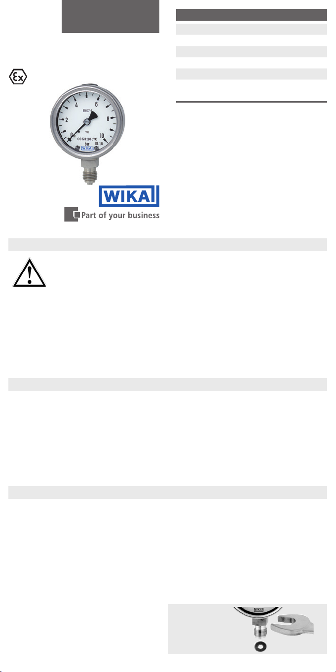
When screwing gauges in, the force
required for this must not be applied
through the case, but rather through the
spanner flats (using a suitable tool) provided for this purpose on the square shaft of
standard connections.
Installation with
spanner

Correct sealing of pressure gauge connections with parallel threads must be made
using suitable sealing rings, sealing washers or WIKA profile seals. The sealing of tapered
threads (e.g. NPT threads) is made by providing the thread , with additional sealing
material such as, for example, PTFE tape (EN 837-2).
Spanner flats
Sealing face
Sealing by
the thread
The torque depends on the seal used. Connecting the gauge using a clamp socket or a
union nut is recommended, so that it is easier to orientate the gauge correctly.
When a blow-out device is fitted to a pressure gauge, it must be protected against being
blocked by debris and dirt. With safety pressure gauges (see dial symbol k) it must be
ensured that the free space behind the blow-out back is at least 15 mm.
After mounting, set the compensating valve (if available) from
CLOSE to OPEN.
Temperature effect
When the temperature of the measuring system deviates from
the reference temperature (+20 °C): max. ±0.4 %/10 K of full scale value
IP Ingress protection
Enclosing case IP 65 (EN 60529 / IEC 529)
Operating temperature
Ambient: Model 232 -40 ... +60 °C
Model 233 -20 ... +60 °C
Medium: The permissible medium temperature does not only depend on the instrument
design, but also on the ignition temperature of the surrounding gases, vapours
or dust. Both aspects have to be taken into account. For permissible maximum
medium temperatures see table 1
Attention! In the case of gaseous substances, the temperature may increase due to
compression warming. In these cases it may be necessary to throttle the rate of change
of pressure or reduce the permissible medium temperature.
Table 1: Permissible medium temperature
Temperature class of the ambient
atmosphere (ignition temperature)
T 6 (85 °C < T ≤ 100 °C) +70 °C +70 °C
T 5 (100 °C < T ≤ 135 °C) +85 °C +85 °C
T 4 (135 °C < T ≤ 200 °C) +120 °C +100 °C
T 3 (200 °C < T ≤ 300 °C) +185 °C +100 °C
T 2 (300 °C < T ≤ 450 °C) +200 °C +100 °C
T 1 (T > 450 °C) +200 °C +100 °C
Maximum permissible medium temperature (in
the measuring system)
Models 232
(dry gauges)
Models 233
(liquid-filled gauges)
The effective maximum surface temperature is not only dependant upon these instruments,
but mainly on the respective medium temperature!
Materials
Wetted parts: Stainless steel
Movement: Stainless steel
Dial and pointer: Aluminium
Case, bezel ring: Stainless steel (model 23x.30: with blow-out back)
Window: Laminated safety glass
Installation
Nominal position per EN 837-1 / 9.6.7 figure 9: 90° (
⊥ )
Process connection lower mount (LM) or back mount (BM)
In order to avoid any additional heating, the instruments must not be exposed to direct
solar irradiation while in operation!
Pressure gauges must be earthed via the process connection!
Permissible ambient and operating temperatures
When mounting the pressure gauge it must be ensured that, taking into consideration the
influence of convection and heat radiation, no deviation above or below the permissible
ambient and medium temperatures can occur. The influence of temperature on the display
accuracy must be observed.
 Loading...