

Wijas POW-LCD MULTI Installation And Operation Manual

Flow water heaters type
POW-LCD MULTI
INSTALLATION
AND OPERATION
MANUAL

2
Before using the heater, please read the instructions carefully. In the future
it will benet by its failure-free operation for a long time.
Flow water heaters series POW-LCD MULTI are intended for heating tap water. They can supply hot water to several water outlets located in different rooms. These heaters are equipped
with heating coils which are directly washed by water. Such direct process of heating prevents
scale formation and ensures high efciency and speed of heating water. The microprocessor
system analyses the temperature of inlet and outlet water, the set temperature, and water
consumption of the user. Based on the collected data, it increases or decreases the heating
power in such a way that the water temperature at the outlet corresponded to the temperature
set by the user. Such control of the heater operation ensures the comfort of use and energy
saving. Additionally, the heater is equipped with the possibility of choosing rated power. It is
equipped with air lock sensors which limit, to the minimum, the possibility of damage of the
heating elements due to air locking of the water distribution system, as well as the system
adjusting the temperature drop caused by the drop of supply voltage.
Heaters can additionally heat water that was pre-heated, e.g. with the use of the solar system
which at the heater inlet cannot exceed 60OC.
• The device cannot be installed in rooms in which the temperature may
fall below 0OC and in which there is the risk of explosion.
• This equipment is not intended to be used by persons (including children) of lower physical, sensory or mental capability, unless they operate
it under supervision.
• Attention should be paid to children not playing with the equipment.
Installation instructions
The installation and start-up of the POW-LCD MULTI heater should be done by a person
qualied in accordance with the guidelines contained in the Manual. All installation works
should be carried out with disconnected power and water supplies. The heater electrical installation should be conducted in accordance with the binding regulations. The device should be
permanently connected to electrical wiring with ground terminal. The electrical wiring should
be equipped with residual current circuit breaker protecting against electric shock and with a
switch ensuring the disconnection of the device from the power source, in which the distance
between the contacts should be not less than 3 mm.
1. To the place in which the heater is to be installed lead electrical wiring and water distribu-
tion system, using for that the mounting template.
2. Drill holes and mount expansion plugs.
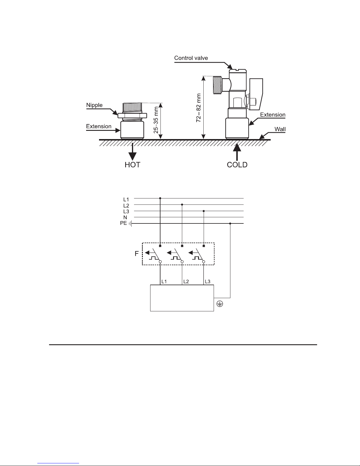
3. Install the control valve with a lter on cold water supply (Fig. 3).
4. Unscrew the fastening screw which holds the housing of the heater located at the bottom
of it (Fig. 1), take off the cover and disconnect the ribbon cable by taking the plug out of
the socket marked “LCD” (Fig. 2).
5. Select rated power by transferring the link to a proper place on a contact marked MOC
according to the description on the sticker.
6. Screw the heater to the wall with the use of fastening screws, having earlier run the power
cable through the hole.
7. Check the starting of pressure switch.
3
8. Remove the securing blanking plugs from water pipes.
9. Connect the heater to the water distribution system (Fig. 5 service line marked 14, outlet
marked 15)
10. Switch on the water supplying the heater and check the tightness of the connections.
11. Connect the heater to the electrical wiring in accordance with Figure 4.
12. Connect the ribbon cable by inserting the plug with the proper side to the socked marked
“LCD”, see (Fig. 2).
13. Put on the housing and screw it with a fastening screw.
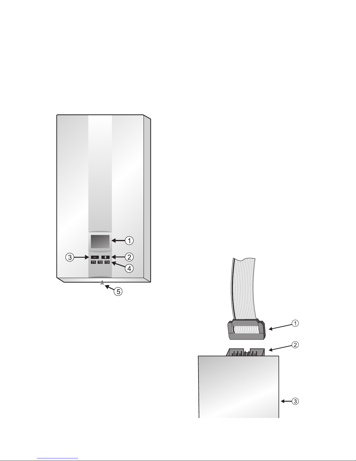
Fig. 2 Display board
with ribbon cable
1. Plug
2. Socket marked “LCD”
3. Display board
Fig. 1 Heater housing
1. Display
2. Button increasing the set temperature
3. Button decreasing the set temperature
4. Memory buttons of the set temperature
5. The screw fastening the housing
4
Fig. 3.
Starting
In order to remove air from the water distribution system and the heater, before turning the
power on, open the hot water valve for approx. 20 seconds in order to remove air bubbles
from the system. Then, turn the power on. Open the hot water valve waiting till the device has
achieved full operational readiness (approx. 5 seconds) beginning the process of heating – in
the lower part of display lines will be shown indicating (in percent) the heating power of the
heater. Close the hot water valve. The heating process is automatically turned off – the lines
previously indicating the heating power will disappear from the display.
Fig. 4 Diagram of electrical wiring
Water heater
 Loading...