

Wigersma & Sikkema UNIGAS 300 Installation, Operating And Maintenance Manual
Installation, operating and maintenance manual
UNIGAS 300

Installation, operating and maintenance manual UNIGAS 300
DDG6004MHGB/08-2017/Rev.A2 Software version from M 1.3.40 and D 2.3.37 1
All rights reserved.
Copyright © 2017 Wigersma & Sikkema B.V.
All the figures and descriptions in this installation, operating and maintenance manual have been compiled
only after careful checking. Despite this, however, the possibility of errors cannot be completely eliminated.
Therefore, no guarantee can be given for completeness or for the content. Also, the manual cannot be taken
as giving assurance with regard to product characteristics. Furthermore, characteristics are also described that
are only available as options.
The right is reserved to make changes in the course of technical development. We would be very grateful for
suggestions for improvement and notification of any errors, etc.
With regard to extended product liability the data and material characteristics given should only be
taken as guide values and must always be individually checked and corrected where applicable. This
particularly applies where safety aspects must be taken into account.
Further support can be obtained from the branch or representative responsible for your area. The address is
printed on the back of this manual or simply enquire Wigersma & Sikkema B.V.
Passing this manual to third parties and its duplication, in full or in part, are only allowed with written permission
from Wigersma & Sikkema B.V.
Preface
This manual provides important information about the use of the UNIGAS 300. Please read this
manual carefully.
Various remarks and warnings in this manual are marked with symbols. Read these carefully and
take measures were necessary.
The symbols used have the following meaning:
REMARK
Suggestions and recommendations to make tasks easier.
NOTE
A note draws user's attention to potential problems.
WARNING
If the procedure is not carried out correctly, a dangerous situation may
develop, or data or settings may be lost.
The guarantee becomes invalid if the product described here is not handled properly, repaired or modified by
unauthorized persons or if replacement parts are used which are not genuine parts from Wigersma & Sikkema
B.V.

Installation, operating and maintenance manual UNIGAS 300
DDG6004MHGB/08-2017/Rev.A2 Software version from M 1.3.40 and D 2.3.37 2
Table of contents
1 Introduction ................................................................................................................. 3
2 Explosion safety instructions (Ex) ............................................................................ 5
3 MID and conversion functions ................................................................................... 6
3.1 Measurement Instruments Directive (MID) .......................................................................................... 6
3.2 Conversion functions ........................................................................................................................... 7
3.2.1 Gas meter error curve correction ................................................................................................... 9
3.2.2 Handling conversion functions ....................................................................................................... 9
3.2.3 Determining the flow rate and consumption .................................................................................. 9
3.2.4 Loggers and log books................................................................................................................. 10
3.3 Other functions .................................................................................................................................. 12
3.3.1 Impulse outputs ............................................................................................................................ 12
3.3.2 Alarm outputs ............................................................................................................................... 12
3.3.3 Battery consumption counter ....................................................................................................... 12
4 Installation ................................................................................................................. 13
4.1 Main components .............................................................................................................................. 13
4.2 Connections ....................................................................................................................................... 15
4.3 Connecting a gas meter with encoder output .................................................................................... 16
4.4 Mounting and connecting cables ....................................................................................................... 17
4.5 Temperature sensor .......................................................................................................................... 19
4.6 Pressure sensor ................................................................................................................................. 19
5 Sealing layout ........................................................................................................... 21
6 Control and display .................................................................................................. 22
7 Maintenance .............................................................................................................. 29
7.1 Adjusting ............................................................................................................................................ 29
7.2 Replacing the pressure sensor or the temperature sensor ............................................................... 29
8 Replacing the battery ............................................................................................... 32
9 Sensor pockets for temperature sensor ................................................................. 34
10 Counters and registers ............................................................................................ 35
11 Technical specifications .......................................................................................... 44
12 Correction of gas meter measuring error ............................................................... 51
13 Determination of volume difference when two impulse inputs are used ............ 52

Installation, operating and maintenance manual UNIGAS 300
DDG6004MHGB/08-2017/Rev.A2 Software version from M 1.3.40 and D 2.3.37 3
1 Introduction
UNIGAS 300 consists of a processor unit and a temperature sensor, whereas the PT and PTZ versions also
contain a pressure sensor. It is used in combination with a gas meter for conversion of the measured gas
volume.
The gas volume is converted to reference conditions tb and pb according to the formula below:
Z
Z
t
t
p
p
VV
bb
b
Cb
•
+
+
••=
15,273
15,273
Where p is expressed in bar absolute and t in °C, and where Z is calculated on the basis of the algorithm
stored in the instrument.
The electronic system is divided over two PCB’s placed in an aluminium housing.
The bottom of the housing contains a PCB responsible for measurement, conversion and power supply. The
cover contains a PCB responsible for control and read-out through the display or serial communication.
UNIGAS 300 has three optical serial ports.
Other available functions are:
• three programmable LF impulse inputs for gas meters with LF impulse outputs
• Namur input for gas meters with HF impulse output or encoder output
• two alarm inputs for normally close contacts
• two programmable real-time impulse outputs
• two alarm outputs
• programming using software UNITOOL and infrared (IR) communication head or remote through a
modem connection
• serial communication with two permanent infrared connectors, one for connecting a modem and the
other for communication with a process computer
• advanced programmable logger functions
• module space for future applications
• real-time clock
UNIGAS 300 comes in three versions:
• external temperature sensor
• external temperature sensor and internal pressure sensor
• external temperature sensor and external pressure sensor
With regard to conversion, UNIGAS 300 is available in two versions:
• PTZ (conversion on the basis of pressure, temperature and compressibility)
• TZ (conversion on the basis of temperature and compressibility)
UNIGAS 300 can issue several alarm and warning signals. The level on which an alarm or warning is issued
can be set. The alarms and warnings can be set for the pressure measured, the temperature measured and
all flow registers.
UNIGAS 300 is provided with an ingenious circuit to ensure that battery life is not affected when the impulse
outputs are used.

Installation, operating and maintenance manual UNIGAS 300
DDG6004MHGB/08-2017/Rev.A2 Software version from M 1.3.40 and D 2.3.37 4
The scope of delivery at least includes:
• electronic volume conversion device UNIGAS 300
• Declaration of Conformity and Safety instructions
• test report
• configuration report
Accessories (optional):
• Lithium-Thionyl chloride D-cell G8610070000
• Lithium-Thionyl chloride DD-cell G8610080000
• Test valve type BDA 04 for connecting pressure calibration equipment O31300
• Software UNITOOL G6900000
• Universal fastening set including mounting material GG6390
• Flange mounting bracket GG6338
• Infrared communication head GG6000
• Flexible stainless steel connecting hose for pressure connection, 0.5 m GG8710
0.7 m GG8713
1 m GG8711
• Module for activation of communication port for process computer GG6605
• Communication-interface module GG6606D
• IR connector met kabel 1,5 m NN2488S
3 m NN2442S
5 m NN2439S
10 m NN2437S
15 m NN2478S
20 m NN2486S

Installation, operating and maintenance manual UNIGAS 300
DDG6004MHGB/08-2017/Rev.A2 Software version from M 1.3.40 and D 2.3.37 5
2 Explosion safety instructions (Ex)
See DDG6800CVML EU Declaration of Conformity and Safety instructions.
Installation, operating and maintenance manual UNIGAS 300
DDG6004MHGB/08-2017/Rev.A2 Software version from M 1.3.40 and D 2.3.37 6
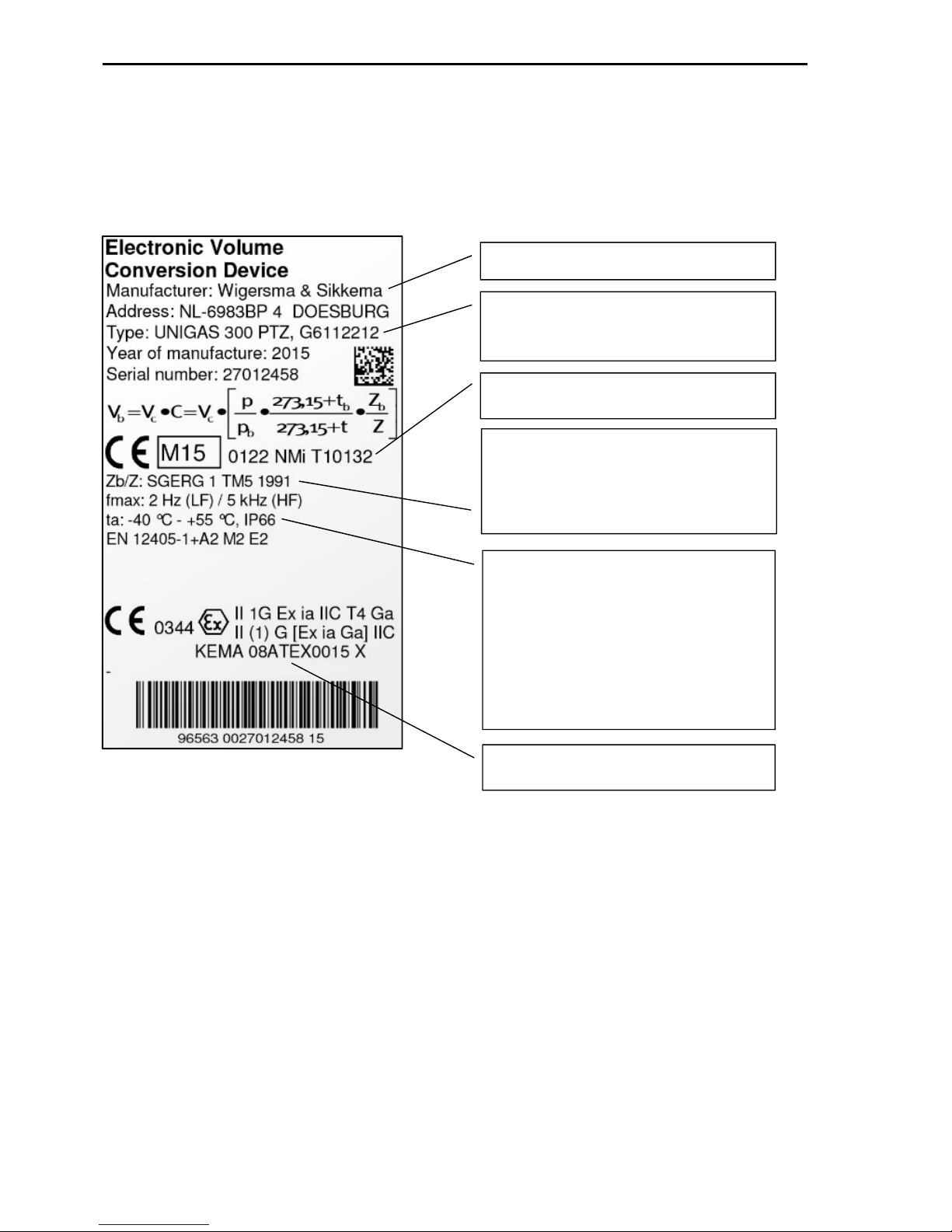
Manufacturer Wigersma & Sikkema
Data with regard to approval explosion safety
ATEX
Operating conditions:
Ambient temperature range: -40 °C to +55 °C
Mechanical environment class: M2, suitable
for significant and high levels of vibration.
Electromagnetic environment class E2,
suitable for light industrial environments.
Additional: suitable for outdoor use.
Data for identification of the instrument and
metrological function (TZ and PTZ)
Conversion algorithms:
- AGA NX19 modified (Gasunie)
- SGERG TM5 1991 method 1-4
- AGA 8 gross method 1
Data for approval metrology MID, certificate
number
3 MID and conversion functions
3.1 Measurement Instruments Directive (MID)
UNIGAS 300 is MID-approved and complies with standard EN12405-1 +A2.
Calibration-relevant data are stated on the main label at the front of the UNIGAS 300 housing.
The main label contains the following data:
Figure 1. Main label
The values of impulse ratios, gas composition, gas temperature range and pressure ranges, serial numbers
pressure sensor and temperature sensor, reference pressure and reference temperature can be shown on the
display. See menu items: ►9; System, ►7; Inputs and outputs and ►2; Parameters.
Also see chapter 6; Human interface and control.
Maintenance and repair:
It is permitted for the UNIGAS 300 owner to install or replace modules and to replace the battery.
After every repair, UNIGAS 300 must be verified again in an accredited laboratory.
Installation, operating and maintenance manual UNIGAS 300
DDG6004MHGB/08-2017/Rev.A2 Software version from M 1.3.40 and D 2.3.37 7
3.2 Conversion functions
UNIGAS 300 has three inputs of which input 1 can be configured for connecting a gas meter with an LF impulse
output, an HF impulse output or an encoder output.
Inputs 2 and 3 are only suitable for connection of a gas meter with an LF impulse output.
Several counters are connected to the three inputs. Counters for correcting the gas meter measuring error and
counters for conversion are connected to input 1.
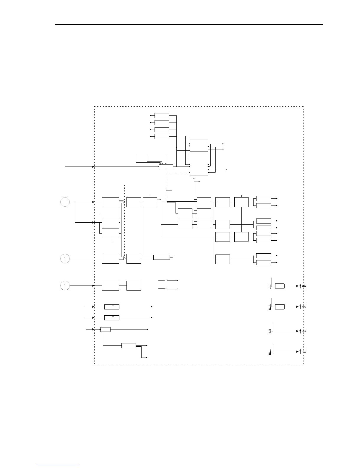
Figure 3 shows the interrelations between conversion and other functions. Chapter 10 contains a further
explanation of all counters and registers present in UNIGAS 300.
status bit
1.10: external_supply
1.11: reset
service registers:
U_batt
AH_new
AH_used
operation
status bit
1.0: empty_battery
2.13: battery_exchanged
alarm Vm2 - Vm1
status bit
3.8: alarm_input_1
status bit
3.9: alarm_input_2
supply
control
external supply
battery
status
gas meter:
LF
Gas meter:
LF
Vm3INP3DIV
alarm contact 2
alarm contact 1
INP2DIV
status bit
1.9: alarm_Encoder
LF3 input
LF2 input
Vm2
status register 1, 2, 3
bit 0..n
status register 1, 2, 3
bit 0..n
switch
alarm output 2
3 x 16 positions
alarm output 2
alarm output 1
status bit 1.5:
alarm_programming_switch
programming switch
tamper switch
status bit 1.4:
alarm_open_casing
Status bit
2.12: alarm_volume_difference
Vc1_60
Out1_div
Vb1
Vb1 err
Vm1
Vc1
Vm2
Vm3
impulse output 1
Out2_div
Vb1
Vb1 err
Vm1
Vc1
Vm2
Vm3
switch
alarm output 1
3 x 16 positions
switch
impulse output 2
6 positions
impulse output 2
statusbit 3.7:
warning_Vc1_60
warning
Vc1_60
switch
impulse output 1
6 positions
alarm
Vc1_60
status bit 3.6:
alarm_Vc1_60
warning
p max
warning
p min
warning
t max
metrological limits:
pmin, pmax
tmin, tmax
warning
t min
error curve correction
(lineair interpolation)
LF, Encoder: Cf=1
HF: Cf1 @ Qf1(Qmin gas
meter)
Cf2 @ Qf2
.................
Cf9 @ Qf9
Cf10 @ Qf10 (Qmax gas
meter)
T,p
p meter
T meter
Gas meter:
LF,
HF,
Encoder
Gasmeter
status bits
1.7: NAMUR_short_circuit
1.8: NAMUR_interruption
INP1DIV
Encoder
decoder
INP1DIV
NAMUR input
Vm1
Vc1
LF1 input
switch
Input_1
4 positions:
-Enoder to Vm2
-LF
-HF
-Encoder
Gas meters under
measuring conditions
status bit
2.4: warning_p_min
status bit
2.7: warning_t_max
tmeasure
adjustment:
p_offset
tcorr_min
tcorr_0
tcorr_max
status bit
2.5: warning_p_max
status bit
2.6: warning_t_min
switch
flow rate
determination
4 positions:
n= 2, 3, 6, 12
x 5 minutes
Qc1_nx5
Qb1_nx5Qb1_5
Cf
Vb1_err
Qb1_instQc1_inst
Vc1_err
Qc1_5
Vb1_60
Vb1
C = p/pb x Tb/T
x Zb/Z
status bits
1.2: alarm_pressure
1.3: alarm_temperature
2.14: error_p_of_t
2.9: alarm_p_max
2.8: alarm_p_min
2.11: alarm_t_max
2.10: alarm_t_min
p, t
A/D converter
p,t
C
Z/Zbfix
alarm
Qb1_nx5
status bit 3.0:
alarm_Qb1_nx5
status bit 3.1:
warning_Qb1_nx5
status bit 3.5:
warning_Qc1_nx5
status bit 3.3:
warning_Vb1_60
status bit 3.4:
alarm_Qc1_nx5
alarm
Vb1_60
warning
Vb1_60
alarm
Qc1_nx5
warning
Qc1_nx5
warning
Qb1_nx5
status bit 3.2:
alarm_Vb1_60
statusbits
2.15: fout_in_Zb
1.1: fout_in_Z_of_Zb
calculation of Z
and Zb
gas parameters:
CO2, H2,N2,
d, Hs
tb, pb
pfix, tfix
Z
Z/Zb
Figure 2. Functions in block diagram
When using a gas meter with two LF impulse outputs, receipt of the impulses of one of the impulse outputs
can be checked. For that purpose the counter readings of input 2 are compared with those of input 1. Also see
chapter 13.
When using a gas meter with both an LF impulse output and an encoder output, receipt of the LF impulses
can be checked with the aid of the encoder. For that purpose the LF impulse output of the gas meter is
connected to input 1 of UNIGAS 300, whereas input 2 is configured for connecting the encoder output of the
gas meter. In this application the encoder counter is only read out once every 5-min interval in order to reduce
the energy consumption and to extend battery life.
Dependent on the version, T, TZ, PT and PTZ (see main label), the conversion is carried out as follows:

Installation, operating and maintenance manual UNIGAS 300
DDG6004MHGB/08-2017/Rev.A2 Software version from M 1.3.40 and D 2.3.37 8
T: conversion with C=pfix/pb x (tb + 273.15)/(t + 273.15) x 1(Z-Zbfix)
TZ: conversion with C=pfix/pb x (tb + 273.15)/(t + 273.15) x Zb/Z
PT: conversion with C=p/pb x (tb + 273.15)/(t + 273.15) x 1/(Z/Zbfix)
PTZ: conversion with C=p/pb x (tb + 273.15)/(t + 273.15) x Zbfix/Z
where pfix, tfix and Z/Zbfix are fixed, preset values.
If an error condition occurs for pressure or temperature, or in determining the compressibility, or in the event
of a CRC error in the firmware for the conversion functions, conversion will be continued as described below,
with replacement values pfix, tfix or Z/Zbfix being used for pressure, temperature, Z or Zb.
The error condition is indicated by a blinking exclamation mark (!) in the display (display in main screen 1, see
chapter 6).
In the error condition:
• counting continues in Vm1 and Vc1
• conversion in Vb is stopped
• the relevant status bit is set (see chapter 6):
o pressure measurement fails or is outside range of pmin to pmax: alarm pressure and error p or t
o temperature measurement fails or is outside range of tmin to tmax: alarm t and error p or t
o determination of Z fails: error Z or Zb
o Zb determination fails: error Z or Zb and error Zb
o CRC error in software responsible for conversion: CRC error conversion
• counting will continue in Vc1err
• conversion takes place in Vb1err with relevant replacement values
o pressure measurement fails or is outside range of pmin to pmax: t and pfix
o temperature measurement fails or is outside range of tmin to tmax: p and tfix
o determination of Z fails: p, t and Z/Zbfix
o Zb determination fails: p, t and Z/Zbfix
o CRC error in software responsible for conversion: p, t and Z/Zb
• the display shows the values of pfix, tfix or Z/Zbfix for p, t and Z/Zb.
The responses to an error condition as described above, apply to an instrument with conversion on the basis
of PTZ. For the other versions, T, TZ, PT, conversion for p, t or Z and Zb takes place with tfix, pfix and Zbfix,
so the response to failure of p, t, Z or Zb does not apply.
The compressibility Z and Zb are calculated according to an algorithm. The following algorithms are available
for UNIGAS 300:
• AGA NX19 modified (Gasunie)
• SGERG TM5 1991 method 1-4
• AGA 8 gross method 1
The algorithm stored in UNIGAS 300 (see main label), is a complete algorithm. This means that interpolation
or tables are not applied. Consequently, the accuracy of the calculation of Z or Zb will match the accuracy of
the algorithm itself.
Specific gas compositions are known for which - at certain temperatures - the compressibility cannot be
calculated correctly by the algorithm. UNIGAS 300 itself will detect such a case and handle it as a failing Z or
Zb calculation and continue the conversion as described above.

Installation, operating and maintenance manual UNIGAS 300
DDG6004MHGB/08-2017/Rev.A2 Software version from M 1.3.40 and D 2.3.37 9
The following calibration characteristics can be modified using the UNITOOL software.
Input 1 LF 0.1 – 100000.0 impulses/m3
Input 1 HF 0.01 – 100000.00 impulses/m3
Input 2 0.1 – 100.0 impulses/m3
Input 3 0.1 – 100.0 impulses/m3
CO2 0 – 30.00 mol %
H2 0 – 10.00 mol %
N2 0 – 50.00 mol %
d 0.5000 – 0.9000 - (at 0 °C)
Hs 14.00 – 48.00 MJ/m3 (at 25°C)
Z/Z
bfix
0.5000 – 1.5000 -
Measuring interval p and t 5-25 s (set as standard at 25 s)
tb 0-25.00 °C (set as standard at 0 °C)
pb 800.00 – 1200.00 mbar (set as standard at 1013.25 mbar)
Z and Zb calculation on / off -
UNIGAS 300 will not accept a value outside the defined range.
Writing is protected by a calibration switch which is to be actuated during programming. Changes are stored
in the calibration log book, see 3.2.4.
3.2.1 Gas meter error curve correction
UNIGAS 300 features a function for error correction of a gas meter. This correction is possible if the highfrequency impulse input on UNIGAS 300 is used. The error correction complies with standard EN12405-1 +A2.
The corrected volume is counted in counter Vc1. This will be discussed further in chapter 12.
If a low-frequency impulse or encoder input is used, the function of error correction of the gas meter is switched
off, counter Vc1 is equal to Vm1 and Vc1 cannot be set.
3.2.2 Handling conversion functions
Pressure, temperature and compressibility are measured and calculated every measuring interval. The
conversion depends on the signal input used:
• LF: real-time conversion at descending flank of the gas meter impulse
• HF: every second at presence of gas meter impulse(s)
• encoder: every measuring interval directly following the measurement of pressure and temperature
and determination of compressibility.
3.2.3 Determining the flow rate and consumption
UNIGAS 300 determines the flow rate for input 1
• Instantaneous flow rate:
o LF: based on the interval between the two most recent impulses (Qb1_inst and Qc1_inst)
o HF: based on the received number of impulses per second (Qb1_inst and Qc1_inst)
o encoder: based on the measuring interval (Qb1_inst and Qc1_inst)
• Consumption on the basis of an interval:
o the measured volume for 5 min (Qb1_5 and Qc1_5)
o a moving average of a series of 5-min values (Qb1_nx5 and Qc1_nx5)
o consumption in a clock hour (Vb_60 and Vc_60).

Installation, operating and maintenance manual UNIGAS 300
DDG6004MHGB/08-2017/Rev.A2 Software version from M 1.3.40 and D 2.3.37 10
3.2.4 Loggers and log books
UNIGAS 300 is equipped with ample memory for data storage. UNIGAS 300 contains the following loggers
and log books. A list of loggers follows below.
1 Interval logger (load-profile): logging takes place every 5 min. The logged data can be displayed as 5,
10, 15, 30 or 60-min values. The characteristics of interval logger are:
• 150 days (43,200 items), ring memory
• readable on display (menu item 4, see chapter 6) and through serial communication
Stored items include:
• date/time
• Vb1
• Vb1err
• Vm1
• Vc1
• Vm2
• Vm3
• t
• p
• status registers 1, 2 and 3
* From software version D 2.3.37, the function has been added that allows channel 6 (Vm3) of the interval
logger to be set for logging of Hs values (see also table "Gas Composition and Redirection on page 39).
When reading the interval logger, for Hs the weighted average, based on Vb, is output.
2 Day logger: logging takes place every day (24 h). This moment can be set and as standard it is set at
6:00 hours (end of a gas day).
Characteristics:
• 100 days, ring memory
• readable on display (menu item 5, see chapter 6) and through serial communication
Stored items include:
• date/time
• Vb1
• Vb1err
• Vm1
• Vc1
• Vm2
• Vm3
• t
• p
• status registers 1, 2 and 3
3 Month logger: every month UNIGAS 300 logs current values. This logging takes place on the last day of
the month at a preset time (as standard: 6:00 hours).
Characteristics:
• 60 items (5 years), ring memory
• readable on display (menu item 6, see chapter 6) and through serial communication

Installation, operating and maintenance manual UNIGAS 300
DDG6004MHGB/08-2017/Rev.A2 Software version from M 1.3.40 and D 2.3.37 11
Stored items include:
• date/time
• Vb1
• Vb1err
• Vm1
• Vc1
• Vm2
• Vm3
• t
• p
• status registers 1, 2 and 3
The following applies to all loggers:
• Each storage is provided with a CRC. If, when reading takes place, the CRC does not equal the
calculated CRC, the data are not shown.
• All counter readings are stored with a resolution of 1 m³.
Two log books are present in UNIGAS 300.
1 Status log book: each status message is logged with a date/time stamp.
Characteristics:
• 360 items, ring memory
• readable through serial communication
Stored items include:
• date/time
• bit number and status register number, including the information regarding the nature of the status
message (event or start and end of a condition)
2 Calibration log book: every change of the value of calibration-relevant parameters is logged with a
date/time stamp.
Characteristics:
• 360 items, ring memory
• readable through serial communication
Stored items include:
• date/time
• OBIS code modified parameter
• old value modified parameter
• new value modified parameter
• Vc1 at the moment of programming
• Vb1 at the moment of programming
• value of status register 1
• value of status register 2
• value of status register 3

Installation, operating and maintenance manual UNIGAS 300
DDG6004MHGB/08-2017/Rev.A2 Software version from M 1.3.40 and D 2.3.37 12
3.3 Other functions
3.3.1 Impulse outputs
The two impulse outputs can be coupled to one of the six counters. The scaling factor can freely be configured
for each impulse output between 1 and 100 m3/impulse.
Impulse issue takes place real-time at a maximum frequency of 2 Hz. The scaling factor must be set
in regards to this maximum frequency to prevent that impulses are temporarily buffered by UNIGAS
300 at pmax and Qmax.
3.3.2 Alarm outputs
The two alarm outputs can be coupled to a status bit from one of the three status registers. At the moment
when the status bit is created, an impulse of 0.1 s is issued. As long as the status bit is active, a 0.1-s impulse
is issued every 5-min interval.
3.3.3 Battery consumption counter
UNIGAS 300 is provided with a battery consumption counter. This device calculates the used battery capacity
on the basis of the time passed and the total of the consumption of the functions performed (pressure and
temperature measurement, communication and encoder or HF input).
The battery consumption counter will stop as soon as an external supply is connected. If this external supply
should fail, the battery consumption counter will resume counting.
When the battery is replaced by means of menu item 10, the battery consumption counter will be reset.

Installation, operating and maintenance manual UNIGAS 300
DDG6004MHGB/08-2017/Rev.A2 Software version from M 1.3.40 and D 2.3.37 13
4 Installation
The UNIGAS 300 housing is IP66 (jet-proof) in accordance with EN 60529 and can be installed outdoors. See
chapter 2; Explosion safety instructions (Ex).
Mounting
A mounting plate is available for UNIGAS 300 that can be used to mount UNIGAS 300 on a wall, in a cupboard
or on a gas meter. A universal flange mounting bracket is also available that can be used in combination with
the above mounting plate to mount UNIGAS 300 on a gas meter flange.
4.1 Main components
Front
2
1
More info: Press key
UNIGAS 300
Figure 3. Front view UNIGAS 300
1: Main label, see chapter 3.
2: Housing lock. Unscrew these two bolts until the bolt heads are roughly level with the UNIGAS 300 front.
Then open the housing on the right-hand side. The seal may stick, so it may take some effort to open
the housing.
3: Pressure sensor and connection. For UNIGAS 300 supplied witch an external pressure sensor, a cable
gland is here. The external pressure sensor comes with a cable of approx. 3 m. It is not permitted to cut
this cable. Any excess cable must be tied up.
4: Security seal. The housing can be sealed by affixing a security wire seal.
5: Cable for temperature sensor. The temperature sensor comes with a cable of approx. 3 m. It is not
permitted to cut this cable. Any excess cable must be tied up.
6: Communication port for reading out and configuring UNIGAS 300 on site. This communication port is
suitable for use of an infrared communication head with the UNITOOL software.

Installation, operating and maintenance manual UNIGAS 300
DDG6004MHGB/08-2017/Rev.A2 Software version from M 1.3.40 and D 2.3.37 14
7: Keypad for controlling UNIGAS 300.
8: Breather opening for pressure equalisation between UNIGAS 300 and ambient atmosphere. Behind the
breather opening a membrane is placed that prevents ingress of moisture.
Take care not to damage the membrane.
9: Communication port 1 for remote communication, including connection of a modem using an infrared
connector. This infrared connector is shown in the figure.
10: Communication port 2 for communication with, e.g., a process computer. Through this communication
port the gas consumer can read out data on consumption etc. This communication port is specifically
intended for local and frequent data readout. Reading out frequently does not affect the performance of
UNIGAS 300. It does reduce the service life of the battery. To activate the port a module must be placed.
Application notes are available for connecting the port to an RS232, USB or TTL serial port. Contact
Wigersma & Sikkema for more information.
11: Dot matrix display. The display is activated when one of the navigation keys is operated. If the navigation
keys are not operated for 1 min, the display will be switched off.
Inside
Figure 4. Interior view UNIGAS 300
1: Connection for battery.
2: Jumper for battery power or external power. When external power is used, this jumper must be placed
in the position EXT; when battery power is used this jumper must be in the position BATT. If this jumper
is in the position EXT while no external power is available, the system will automatically switch to battery
power.
When external power is used and the jumper is in the position BATT, UNIGAS 300 will shut down.
When the HF impulse input is used, external power is necessary.
3: Calibration lock / calibration switch. The calibration switch must be actuated while programming a
calibration parameter. After actuation the lock remains open for 15 seconds. The calibration switch can
be operated with a pin (e.g. with the tip of ballpoint). The calibration switch is to be sealed with an
adhesive seal.
4: Battery holder. When using a DD cell, the break-off tab that fixes the D cell must be cut.
5: Fixation of the PCB and the protective cover. The bolt is sealed with a sticker seal.
Installation, operating and maintenance manual UNIGAS 300
DDG6004MHGB/08-2017/Rev.A2 Software version from M 1.3.40 and D 2.3.37 15
6: Connection for grounding.
7: Module connector with protective cap (PCB cover not shown in figure 4). Nothing but Wigersma &
Sikkema modules can be connected to his module connector. This module connector is retroactionfree, which means that manipulation of the module connector will not affect the calibration functions.
8: Tamper switch. UNIGAS 300 detects the opening of the housing and records this event in status register
1.
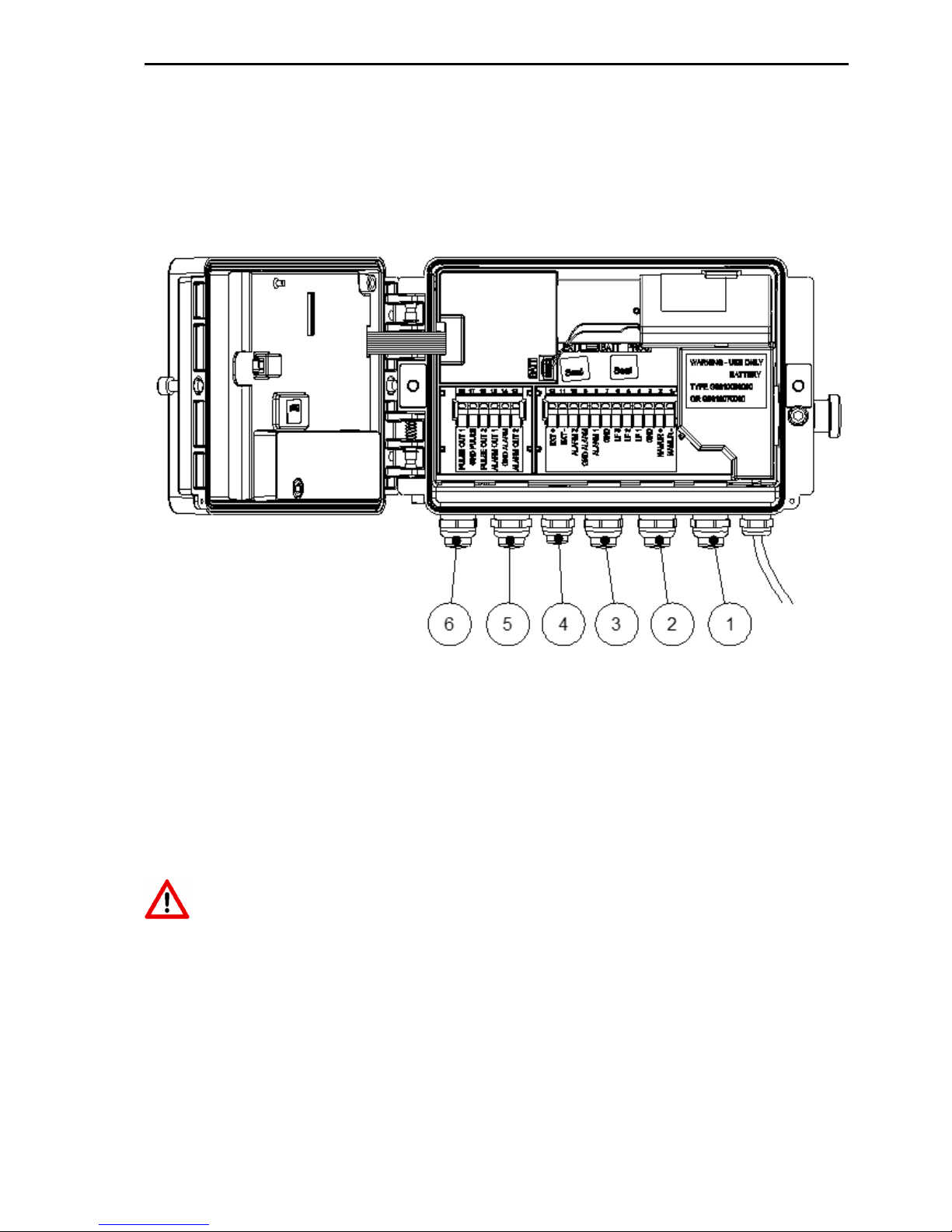
4.2 Connections
Figure 5. Connections
1: Cable gland for input 1 (LF / HF / encoder)
2: Cable gland for input 2 (LF) and input 3 (LF)
3: Cable gland for alarm inputs 1 and 2
4: Cable gland for external power supply
5: Cable gland for alarm outputs 1 and 2
6: Cable gland for impulse outputs 1 and 2
Unused cable glands must be sealed with the supplied sealing caps.
 Loading...