

Wige CUNIMA MCU Operation Instructions

CUNIMA MCU [2]
Operation Instructions
Congratulations for working with the Mini-HD-camera CUNIMA MCU[2]! You have chosen a high
quality camera which allows numerous ways to be used, for example as an onboard cam in
motorsports, as a fixed camera position on stage at concerts or even for stereoscopic 3D-productions.
The compact design looks quite similar to CUNIMA MCU[1] and it has almost the same dimensions,
but the motor that drives the body is completely new - new sensor, new electronics, new features!
With these, the CUNIMA MCU[2] fits perfectly into your advanced film- and stereo3D-production
workflow or live-broadcast - you name it!
Version 1.1 (FW1.10.0)
Last edited on: 05-02-2013
Features and specifications are subject to change without notice.

2
1. CONTENTS
2. Introduction and Key Features
3
2.1 Cunima MCU[2] Specifications
4
2.2 Package Contents
5
3. Setup
6
3.1 Camera setup
6
3.2 Connectors on the CUNIMA
6
3.3 Lens setup
7
3.4 Backfocus adjustment
8
3.5 Iris remote control
8
3.6 Inter Camera Communication (ICC)
10
3.7 Cleaning of the camera
10
4. Operation
11
4.1 Analog Gain
11
4.2 Edge enhancement
11
4.3 Fixed Pattern Noise Correction
11
4.4 Gamma correction
12
4.5 Shutter Speed / Exposure Time
12
4.6 Operation mode
13
4.7 Image resolution – Scanning format
13
5. RCP – Remote Control Panel
14
5.1 Introduction
14
5.2 Installation
14
5.3 Operation
15
5.4 Menu
17
6. serial protocol
20
6.1. Frame Format
20
6.2. Commands
21
6.3. Remarks
24
3
2. INTRODUCTION AND KEYFEATURES
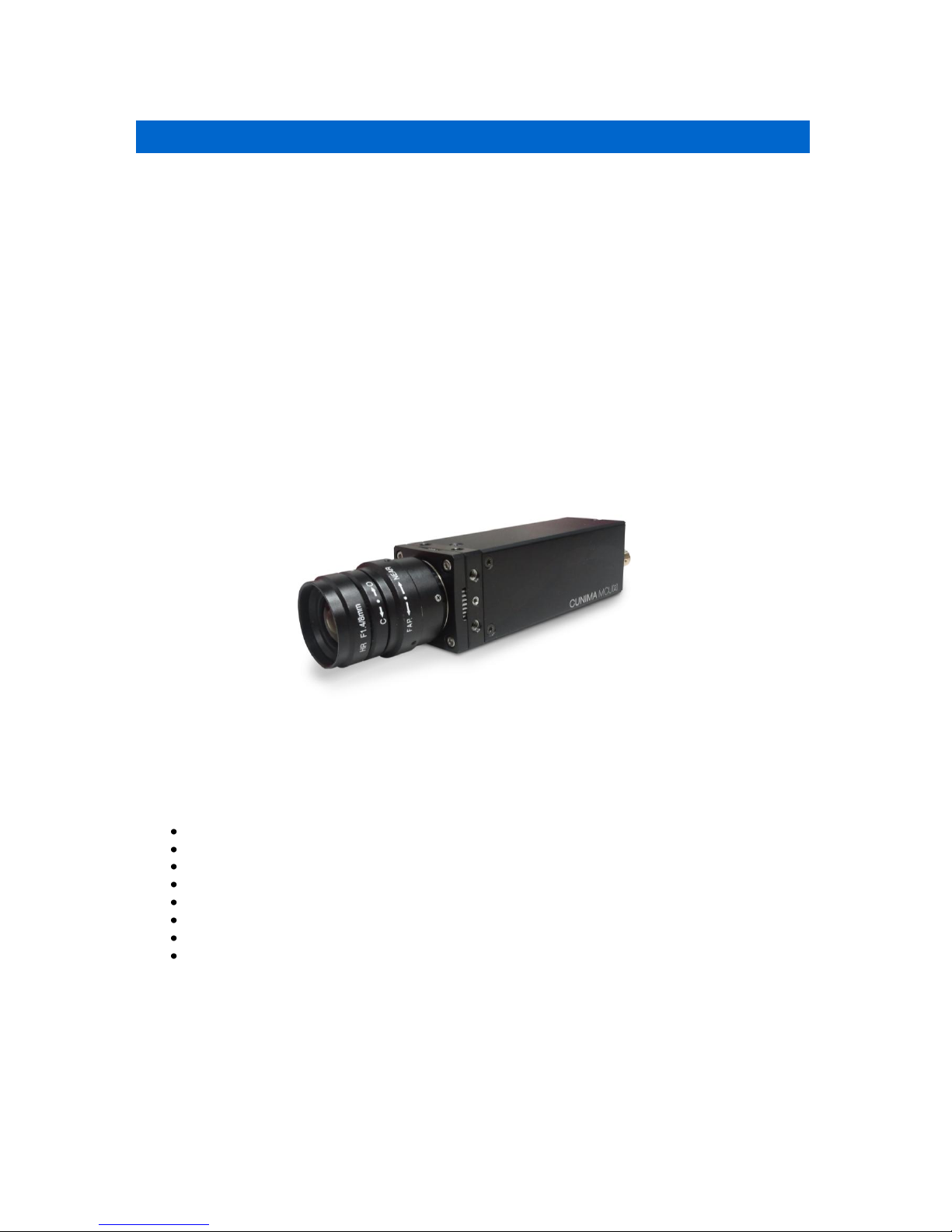
CUNIMA – highest performance, ultra-compact design. In the case of the CUNIMA MCU[2], outer
dimensions of just 36.5 x 36.5 x 111.5 mm provide enough space for a complete HD/SD multi-format
camera - hence an external camera control unit is history, now.
The latest CMOS chip technology and the globally renowned know-how of the German ‘Fraunhofer
Institut’ for Integrated Circuits allow for professional HD operations at a total weight of just 240g and
an incredible maximum power consumption of 5W!
CUNIMA is your perfect partner for sports, entertainment show, reality – you name it!
The CUNIMA’s modular accessory concept permits a continuous and flexible adaptation of the camera
to the respective production requirements. In this area, the wealth of experience gathered by the
globally leading TV production expert, WIGE MEDIA AG, over the course of many years was
incorporated – and the same applies to your individual demands.
Key Features:
Revolutionary, compact design.
No external Camera Control Unit required.
Multi-format scanning system, native HD and SD
4:3 and 16:9 switchable signal generation.
Only 5W of power consumption.
Electronic shutter, programmable gamma LUT’s. (linear, REC 709), User defined Gamma.
Universal remote control via RS-485.
Modular and flexible accessories.

4
2.1 CUNIMA MCU [2] SPECIFICATIONS
Image Sensor
2/3" CMOS Chip
2048 x 1080 pixel, progressive scan
Lens Mount
C-Mount
other mounts on demand
interchangeable glass filters
Scanning Systems
1080p/ 23.98, 24, 25, 29.97, 30 Hz
1080i / 50, 59.94, 60 Hz
720p / 23.98, 24, 25, 29.97, 30, 50, 59.94, 60 Hz
525i / 59.94 Hz*, 4:3 / 16:9 switchable
625i / 50 Hz*, 4:3 / 16:9 switchable
* native SD-format, w/o down conversion
Gamma
On/Off, user-definable LUT's
White Balance
Manual adjustment, user-definable presets
Black Balance
Manual adjustment, user-definable presets
Saturation
Manual adjustment, user-definable presets
Gain
user-definable gain up to 24dB
Shutter
Electronic shutter, variable 10-100%
Sync
Internal or
Genlock BiLevel/Trilevel (Analog & Digital)
Output Signals
HD-SDI (SMPTE-292M)
SDI (SMPTE-259M)
Remote Control
RS-485
Power
9-32 V DC, 3W
Weight
240 g
Dimensions
36.5 x 36.5 x 111.5 mm
Depending on firmware-changes and software-status, these specifications may vary or be mutually
exclusive.
Features and specifications subject to change without notice.
5
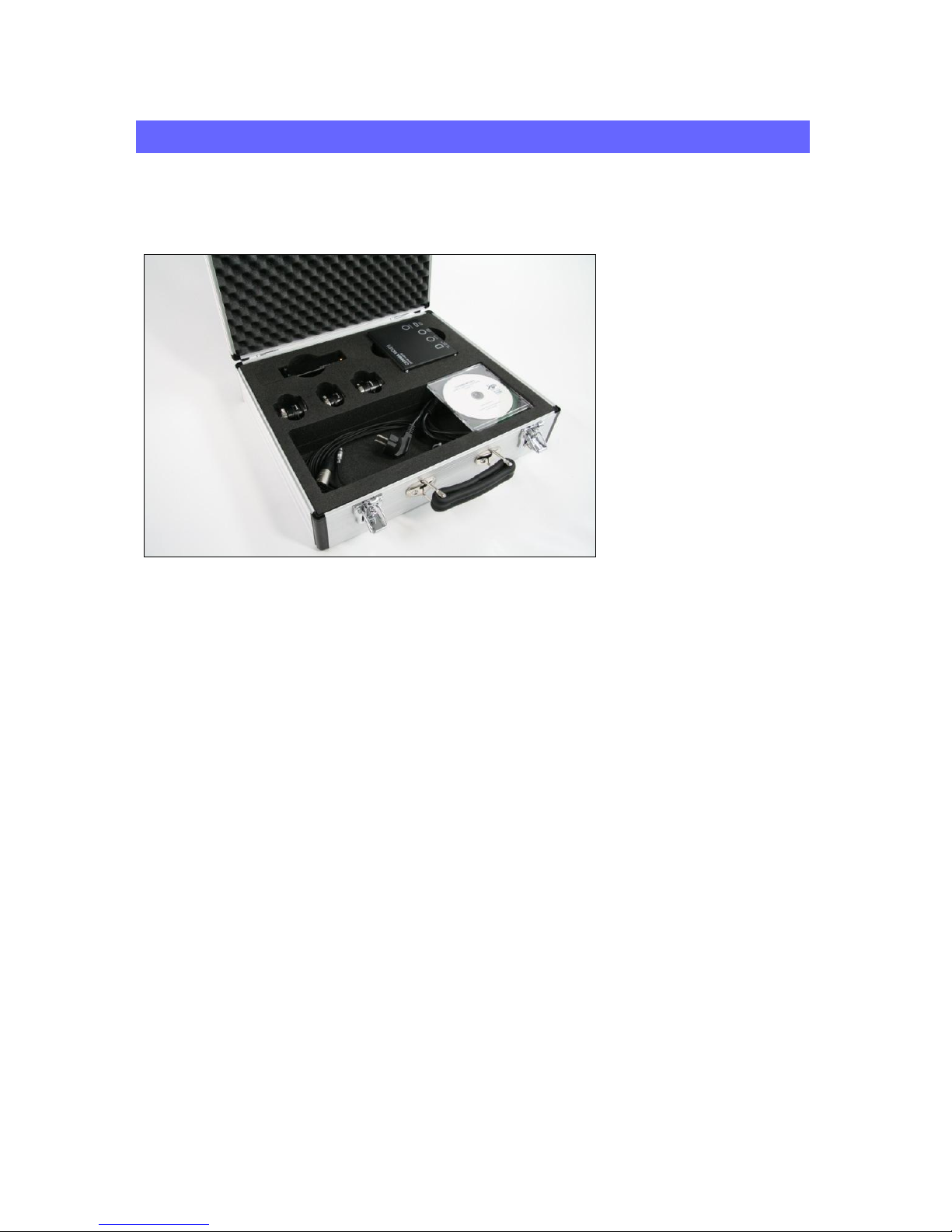
2.2 PACKAGE CONTENTS
This product is delivered with its accessories in a carrying case.
For a smooth workflow, please check if the set is complete before going on production. If one of these
items gets lost, feel free to order it at WIGE MEDIA AG.
Contents:
1x CUNIMA MCU[2] HD-camera
1x Power Supply CUNIMA MCU[2]
1x Device Cable for Power Supply
1x Adaptor Fischer to XLR 7-pole (connection camera to power supply)
1x Adaptor Tripod (1/4 inch and 3/8 inch screws)
3. SETUP
6
3. SETUP
Please notice that due to safety reasons this camera system may only be operated by trained staff!
3.1 CAMERA SETUP
1. Open the carrying case and check if all needed items are included (see chapter 2.2).
2. Remove the power supply and connect it with the cable device to a power source (220V240V). The blue LED on the power supply should lighten up.
3. Connect the camera to the power supply by using the adaptor ‘Fisher to XLR 7-pole’.
4. The captured image should appear at the BNC connector of the camera within seconds and
can then be finished. The setup is now completed and the camera ready for use.
Please note: do not turn the connectors when pulling out the Fisher-cable. To disconnect,
please just remove the cable by pulling straight. Turning it out with force may cause bended
connectors and lead to irreparable damage.
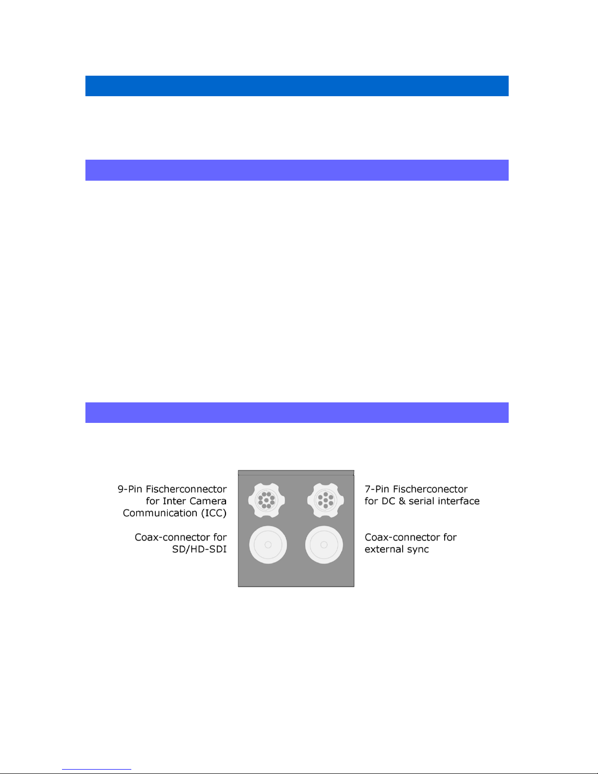
3.2 CONNECTORS OF THE CUNIMA

7
3.3 LENS SETUP
The C-Mount screw is a socket to hold applicable lenses. In some cases, an adaptor-coil is needed to
ensure the correct flange back. This is not exceptional, but a current way to counteract imprecise
manufacturing.
3.2.1. Choosing a lens
Independent of the focal length, there is an important characteristic of C-Mount lenses which should
be considered when choosing a lens. Because of the existence of different sensor dimensions (1/3
inch, ½ inch and2/3 inch) and senor quantities (3x ½ inch or 1x 2/3 inch etc.) and the fact that the
Cunima MCU[2] does contains single CMOS sensor with Beyern-pattern, please only use lenses
which are engineered for that indented purpose (CUNIMA: 2/3 inch single CMOS sensor).
3.2.2. C-Mount thread
1. Please remove the rubber protection of the Cunima MCU[2]. You can see the C-Mount thread
now. Please note that behind the thread is the glass protection of the sensor. This glass
should not be damaged or it may constrain the image quality.
2. Remove the lens and check for possible damages. Please do never mount a damaged lens on
the Cunima MCU[2]. Further damages of the camera because of optical small parts like glass
splinters could occur.
3. Screw the lens into the C-Mount.
4. If the flange back of the lens is not right, you may use the backfocus (see chapter 3.4)
adjustment feature of the CUNIMA MCU [2].
Whenever there is no lens screwed on the C-Mount, please make sure that a protection
rubber protects the cameras glass filters to avoid any damages!
8
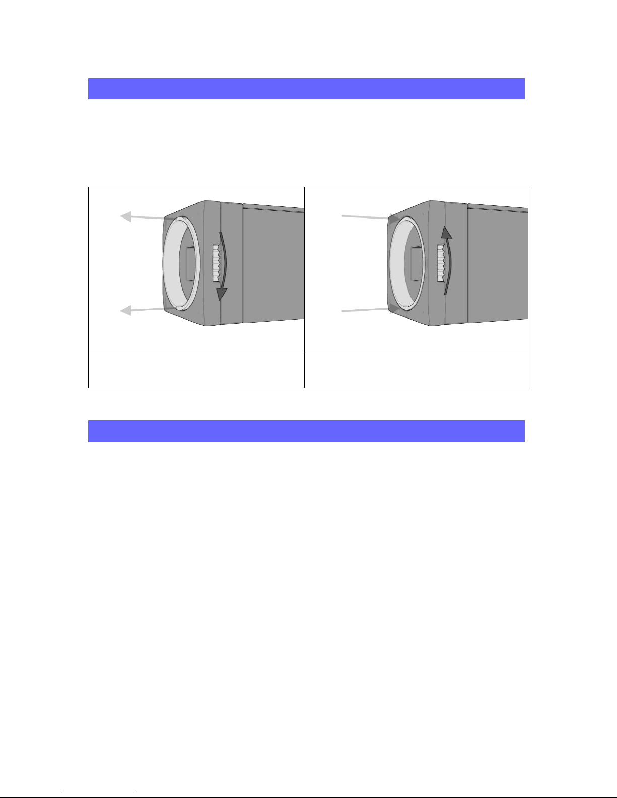
3.4 BACKFOCUS ADJUSTMENT
To ensure that you can use every lens with this camera properly,
the housing of the CUNIMA lets you adjust the backfocus.
To adjust the backfocus, please follow the instructions below:
rotate the gearwheel clockwise to increase the
backfocus
rotate the gearwheel counterclockwise to
decrease the backfocus
3.5 IRIS/FOCUS MOTOR
3.5.1 INSTALLATION
1. To use the iris/focus motor on the CUNIMA, mount it on any of the four sides of the
camera. The two threads on each side of the head of the CUNIMA can be used to fix it.
Make sure to align the gearwheel of the motor with the gearwheel of the lens properly.
2. Connect one male 7Pin plug of the Y-patch cable to the CUNIMA and the other to the
iris/focus remote module.
3. Now connect both parts with the female connector of the y-patch cable to the standard Y-
cable of the CUNIMA and establish the connection to the power supply and the RCP.
4. The green LED of the iris/focus remote module will now flash slowly. This indicates that
the remote module is ready to work. If the green LED stays is illuminated constantly
without flashing, reboot the remote module by pulling out the cable and plugging it back in.
 Loading...