

Wifi-soft Solutions UniBox U50, UniBox U100, UniBox U200, UniBox U500, UniBox U1000 User Manual
...
Unibox User Guide
An intelligent Network Access Controller
Wifisoft Solutions Private Limited

© Copyright 2018, Wifi-soft Solutions Pvt. Ltd.
All rights reserved.
The information contained herein is subject to
change without notice. This document contains proprietary information, which is protected by copyright. No part of this document
may be photocopied, reproduced, or translated into another language without the prior
written consent of Wifi-soft.
Publication Date
Aug 31st , 2018
Applicable Products
The administration guide applies to the following products –
• UniBox U50 & U100
• UniBox U200 & U500
• UniBox U1000, U2500, U5000
Disclaimer
WIFI-SOFT SOLUTIONS PRIVATE LIMITED
MAKES NO WARRANTY OF ANY KIND WITH REGARD TO THIS MATERIAL, INCLUDING, BUT
NOT LIMITED TO, THE IMPLIED WARRANTIES
OF MERCHANTABILITY AND FITNESS FOR A
PARTICULAR PURPOSE.
Wifi-soft shall not be liable for errors contained herein or for incidental or consequential damages in connection with the furnishing, performance, or use of this material.
The only warranties for Wifi-soft products and
services are set forth in the express warranty
statements accompanying such products and
services. Nothing herein should be construed
as constituting an additional warranty. Wifisoft shall not be liable for technical or editorial
errors or omissions contained herein.
Wifi-soft assumes no responsibility for the use
or reliability of its software on equipment that
is not furnished by Wifi-soft.

Unibox Overview
UniBox is a network access controller and a hotspot gateway that helps network administrators
secure and control access to wired or wireless networks. It is used as hotspot controller, network
controller and Internet gateway in variety of businesses, hospitality venues, shopping malls,
hospitals, schools and colleges, transport venues, enterprises and any place where networks need
to be managed. UniBox provides various functions like access control, user management, AAA server,
billing system, multi-WAN router, firewall, URL logging, VPN server, AP controller, bandwidth control,
reporting/analytics and advertisement.
UniBox can be used for managing public wireless (or wired) networks at Wi-Fi hotspots/ hotzones,
campus and public-access networks. It can be used by private enterprises for controlling access to
their private networks, isolating and authenticating guest traffic via a splash page, enforce time and
usage policies and to allow secure and limited access to BYODs by employing self-registering /
requesting for IT approval of their BYOD devices and.
UniBox is an all-in-one gateway controller i.e. it functions both as a firewall and an access controller
as well as an authentication and billing server. It implements a captive portal that restricts
unauthenticated users from getting access to the network resources e.g. Internet. In addition, it also
provides an on-board authentication and billing server to verify the user’s credentials and charge
the user for using the network.
UniBox can be also deployed with a central authentication and billing (OSS/BSS) server. In this case,
UniBox will function in controller-only mode and will use the services offered by the central server.
If the hotspot / hospitality operator wants to manage multiple hotspots centrally then UniBox is
deployed in the controller mode. It works seamlessly with Wifi-soft’s cloud-based management
platform – WiFiLAN.
UniBox comes in different models based on number of concurrent users it can handle. The models
range from 50 concurrent users to 5000 concurrent users.
UniBox comes with built-in access point controller and NMS system. The AP controller is responsible
for controlling and configuring UniMax access points. It also provides a comprehensive NMS system
that provides the real-time status and health of each access point.
In addition, UniBox can be deployed to work with wide range of industry standard wireless access
points like Cisco, Ruckus, Aruba, DLink, Ubiquiti to name a few and can easily be overlaid in any
existing wired or wireless network in a small to large sized networks. The software stack is installed
on standard x86 hardware running Linux variant. This makes UniBox very versatile and is capable of
scaling to support thousands of users on the network.

Primary functions
UniBox is primarily deployed as a network access controller and hotspot gateway to manage
enterprise networks, guest access networks and public Wi-Fi hotspots. It also incorporates various
security functions that are useful for managing enterprise networks –
1. Network Configuration
Unibox provides you the ability to interface and monitor your network by providing various
network configuration and monitoring options. UniBox is deployed as a gateway so it sits
between the private LAN and public WAN / Internet network. UniBox comes with multiple
Ethernet ports. Each port can be configured as WAN or LAN port thus giving flexibility to the
administrator to create multiple LAN segments or configure multiple WAN connections.
The WAN port supports various configuration options like Dynamic and Static IP. Multiple
LAN profiles can be created and each LAN segment can be configured with a separate DHCP
server. In addition, the port can be configured to tag the traffic with VLAN tags.
Other than port configuration, UniBox provides features like DHCP server and DNS that allows administrator to configure IP addressing and to choose specific domain name servers.
Built-in monitoring module, allows to you to monitor all the network elements like wireless
access points, IP cameras, POS terminals, etc in the network. The NAT feature provides network address translation and port forwarding thus enabling access to the internet by the
guests and BYODs as well as secure access to internal devices from the Internet. Unibox also
provides SNMP agents and SNMP traps to interface with third-party NMS systems. Finally
the DDNS feature allows administrators to use DDNS services like anyDNS, no-ip etc that
allows access to UniBox deployed on a dynamic IP.
2. Captive Portals
Captive Portals are displayed to the hotspot and BYOD users when unauthenticated users
try to connect to a Wi-Fi hotspot. The Captive Portal is displayed as a result of redirection of
the client on the network. It provides an interface for the user to provide login information
and pass this information to the Authentication Server for validation. Unibox provides predefined templates for designing captive portals using the click-and-customize method. Alternatively, administrator can also design the captive portal separately and host it on an external web server. UniBox provides customization of logo, branding, images, text and layout
of the captive portals to suit specific branding requirements.
Captive Portals also provide an option for user provisioning (online registration) by requesting the users to create their accounts using a payment option like credit card or PayPal. UniBox manages the complete end-to-end workflow of the user provisioning process.
3. MAC Login / BYOD
Many businesses, especially for non-manufacturing workforce, are witnessing an explosive
demand by the employees to use their own personal devices, like smart phones, tablets and

ultrabooks / laptops to check their emails, access to intranet portals like sharepoint and to
have access to a limited number of web applications servers, while 95% use of these personal
devices is for Internet access. It is an IT nightmare and most of the time, under pressure from
supervisors and higher levels, IT departments are simply allowing these users / personal devices to access the Internet thru company network by having them use the company private
wireless networks, though most of these users are not at all malicious, nonetheless, the security posture of the devices and the websites / content some of them accessing thru the
company network, has potential for security breaches / work / virus infection to company
business servers and other business computers. Unibox allows self-registration of such devices wherein the user of such personal device will request for access from IT department by
filling up a short browser based form splashed thru the Unibox, as user tries to go to Internet,
and then submits the same over to the IT department, which then approves or otherwise
the access and then notify the user via their company email to be of granted access to the
limited BYOD network. This process not only allows approved devices on the network, it also
allows to take away the access if a device is lost / stolen or if an employee leaves the company and at the same time allows companies to enforce policies, bandwidth caps, content
filtering etc.
4. User Authentication and Tracking
Once the user, say an education/residence environment, is provisioned in UniBox, s/he can
use the captive portal to gain access to the network. This involves AAA (Authentication, Authorization and Accounting) services from the RADIUS server. This service is responsible for
validating user’s credentials and providing access to the Internet and any limited internal
web / application servers if so allowed. It also performs accounting function by collecting the
CDR/session records for each user. UniBox running in local authentication mode run an internal AAA server that is responsible for all the AAA services on the network.
5. Billing
UniBox comes with a comprehensive billing module that allows administrators to configure
different billing plans, create access codes, perform credit card clearing, interface with PayPal and generate revenue reports. Most US credit card payment gateways are supported,
and other country payment gateways can be helped with, if there is sufficient demand.
6. Bandwidth control
UniBox comes with many bandwidth control tools that allow administrators to effectively
manage bandwidth among the users. It provides options to enforce group-level or per-user
level bandwidth control rules to ensure optimal use of the network bandwidth.
7. Policy Management
UniBox provides wide range of policies to restrict usage, enforce fair usage and identify misuse of the network. These policies can be applied to group of users and tracked by the administrator on a regular basis.

8. Traffic Management & QoS
UniBox offers various tools to effectively manage and control the data usage on the network
in addition to maintaining QoS. Traffic management can be done at different levels like group
of users, per user, per application or port or a subnet of IP addresses. UniBox provides different policies to enforce fair usage on the network or penalize users who are misusing the
network traffic.
9. Reporting and Analytics
Extensive reporting capabilities allow administrators to keep watch on all the activity on the
network. UniBox also analyzes the data collected from the users and display analytics like
usage trends, OS/Devices used, top users, etc.

Important Concepts
1. RADIUS (AAA)
RADIUS stands for Remote Authentication Dial-In User Service. The protocol is defined by
IETF (Internet Engineering Task Force) and is described in detail in RFC 2865 and RFC 2866.
2. Captive Portal
Captive Portal (AKA – login or landing page) is the page that enforces authentication on the
network managed by UniBox. The Captive Portal can be either hosted inside the UniBox or
can be hosted on an external web server.
3. Bandwidth Control
Bandwidth control mechanisms are required to control the bandwidth for each user on the
network. UniBox offers various bandwidth control functions to help the administrators regulate the bandwidth usage and punish the users who hog the bandwidth.
4. User Provisioning and Management
UniBox provides completely automated mechanism for provisioning users on the public networks like Wi-Fi hotspots. Unauthenticated users are presented a registration page to create
an account online. The registration page may offer billing plans for paid hotspots or UniBox
also allows administrators to add user’s account directly in the system.
User accounts created are generally associated to a particular groups, policies or plans. Users
Internet usage can be restricted based on the plan or groups they belong. Unibox allows you
to configure various restrictions for each user like Session timeout, Concurrency Limit, Idle
Timeout, Upload/Download Rate, Daily Upload/Download Quota, Sessions per day and Usage Quota.
Unibox does comprehensive accounting of each user which provides you with details like
Start time and End time of Sessions, Duration, MAC Addresses, Upload/Download Data Size
per session and the session termination reason. It also maintains Agent and Authentication
history which provides you information about user’s browser, OS, IP/MAC addresses, login
timing, bandwidth usage and more. Administrator also has a privilege to expire, suspend or
activate users or even disconnect the user from the network. Finally the user’s activity and
authentication history can be exported to a PDF or Excel file to analyze it further.
5. Billing
For a paid network like Wi-Fi hotspot, it is necessary to provide online payment option to
the end-users. The billing system allows administrators to charge credit cards, interface with
PayPal, define billing plans, view transactions and configure the payment gateway details.
Before enabling billing, administrator needs add the payment gateway settings in UniBox.

When the user registers for a new account, UniBox passes the credit card details to the payment gateway for processing. If the card is charged successfully, the user’s account is created
in subscriber table and user is given access based on the billing plans he selects.
Similarly, administrator can create different types of prepaid (access) codes or PINs which
can be exported or printed in a business card sized format for distribution. The end user can
enter the prepaid code on the portal page and gain access to the network (Internet) for the
allotted time or bandwidth.
6. SMS Based Login
SMS based login employs two-factor authentication process (also known as OTP – one time
password) to validate the user with his/her mobile number. With the rise in cyber crimes,
many countries require that hotspots operators validate the user’s mobile number at a public WiFi hotspot. SMS based login helps these operators to comply with this requirement.
Additionally, this process also allows the operator to collect mobile/cell phone numbers for
marketing and promotional activities.
How does it work?
When the customer visit your WiFi Hotspot, s/he will see a login page (Captive Portal) requesting them to enter her/his mobile (cell) number. Customer enters the mobile number
along with the other optional details like personal information, email, preferences, etc. On
receiving the information, UniBox sends a SMS with a login code (randomly generated) to
the registered Mobile Number. Customer needs to enter the code on the login page to gain
access to the Internet. UniBox provides different variants to this process to allow operators
to implement different business models on the network.
7. Social Media Integration
Social media is a network of all people who get together as a society over the Internet and
connect with each other for sharing information, knowledge, news, events etc. We have
number of popular social networking websites like Facebook, Twitter, Google and LinkedIn.
There is a rising trend to capture social media information for the users who access Wi-Fi at
public hotspots. Most of the social media websites provide rich API to retrieve user’s profile
that is extremely valuable to companies for profiling users, understanding user trends and
building marketing strategies. For end-user’s perspective, the users don’t need to remember
username and password for each hotspot. Instead they can just use their Facebook ID to gain
access to the hotspot.
UniBox provides different options to validate user’s credentials using their social media pro-
file. It also seamless collects the user’s public information to generate analytics and trends.
8. Activity Logging (URL Tracking)

Activity logging means tracking the user browsing activity and logging the URLs the user visits
while using UniBox managed network. This is an optional feature and can be activated on
need basis. When activated, UniBox starts keeping track of the Internet activity for the user
and logs the activity in a database. Administrators can generate various reports or use the
search tool to find URLs visited by a user on the network. Additionally administrator can log
and archive the information centrally by streaming the information to a remote server. This
may be required for regulatory compliance.
9. Network Monitoring and Alerts
Monitoring allows administrators to check the health of all the network elements like access
points, switches, cameras, printers, etc inside the network. It monitors each element periodically to ensure that the connectivity is intact. If an outage is detected, an alert is generated and sent to the right person so a repair work can be carried out before the end users
get affected.
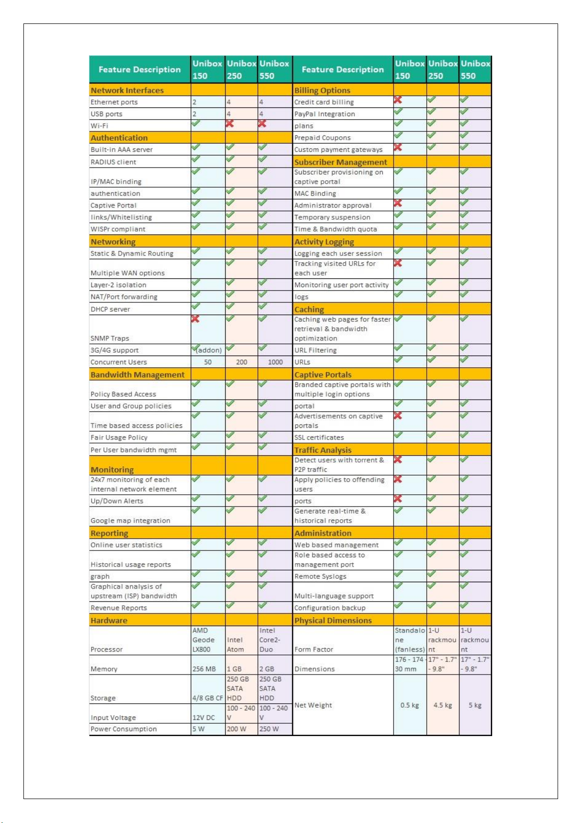
UniBox Models
UniBox is sold in three standard variants –
SMB Models
Models Available : U50 and U100
These models are ideal for small to medium networks that support up to 100 concurrent
devices. They are generally deployed for small hotspots in cafes, retail shops, small offices,
motels, etc. The models are available in a small, compact enclosure and is powered by a
separate 12V DC adapter. It supports 3 gigabit Ethernet ports.
Enterprise Series
Available Models: U200 and U500
This model is ideal for medium sized networks and is capable for support up to 200 to 500
concurrent devices. This UniBox is ideal for medium venues like hotels, motels, shopping
plaza, training institutes, medium sized businesses, etc.
Campus Series
Available Models: U-1000 and U2500
These models are designed for high-traffic, large networks and is capable of handling up to
1000 concurrent users. The model comes in 1-U form factor and comes with 6 gigabit ports.
It is ideal for larger venues like large hotels, schools/colleges, enterprises, etc
Large Campus Series
Models: U5000
These models support large number of concurrent users and provides high throughput. It
comes with 6 gigabit Ethernet ports and 2 SFP+ ports. It is ideal for very large venues like
convention centers, universities, airports and large enterprises.
In addition, you can also order custom model for networks that have more than 5000 concurrent
users or where there is a need for a redundant power supply and redundant LAN side connections
for hook up to a stack of enterprise switches or two core enterprise switches, for better resiliency.
For large scale and critical operations, it is recommended to deploy a pair of controllers in active /
passive mode. The configuration from the active can be backed up along with the user database to
the passive unit (not suitable for hospitality operations, because of dynamic nature of guest
accounts, but a spare unit with configuration restored and user accounts recreated or in case of
external radius server hosting such accounts will work. Table on the next page shows the complete
list of Features, Hardware Specifications and Software Specification for each model.

Installation
This section explains how to install UniBox in your network. UniBox needs to be deployed as a
network gateway so it is installed between the LAN and WAN network. UniBox is always shipped
with two or more Ethernet ports. The photos below display the various components of two UniBox
variants – standalone unit and 1U server unit.
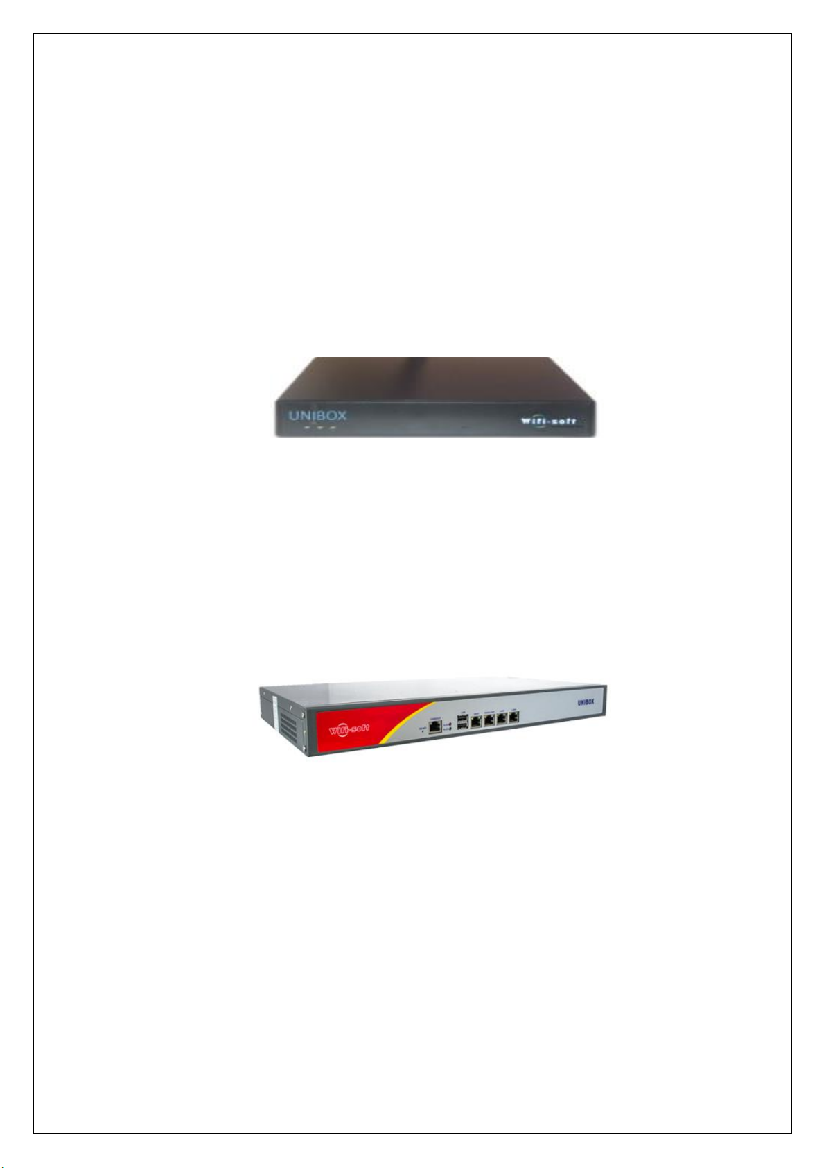
Standalone Unit
UniBox U50/U100
UniBox U-100 standalone unit comes with three Ethernet ports, serial port, two USB ports and a
power jack. The photo shows the various connectors available to the user. The LAN port needs to
be connected to your private network that UniBox will manage. The WAN port needs to be plugged
into your Internet (WAN) connection.
<<Image here>>
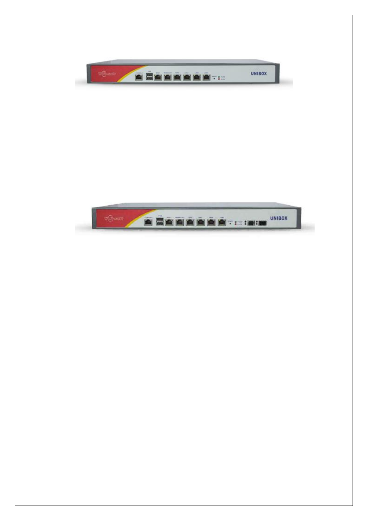
UniBox U-200
UniBox U-200 standalone unit comes in 1U form factor with 4 Ethernet ports, 2 USB ports, serial
port and power jack. The photo shows the various ports available on UniBox U200. Any port can be
configured as WAN or LAN port. The admin can create multiple WAN profile and then assign these
profiles to multiple Ethernet ports. If multiple WAN ports are assigned, then UniBox will be
automatically configured for load balancing and failover.
Similarly any port can be configured as LAN port and multiple LAN profiles can be setup and
assigned to physical LAN ports.
UniBox U-500 /U-1000
UniBox U-500 / U-1000 models comes with a 1U form factor and is generally installed in a server
rack. The unit comes with 6 Gigabit Ethernet ports. The admin is free to chose any port as LAN or
WAN port. Depending on client requirements, the U500 or U1000 might also come with 2 SFP+ ports.
These ports can be assigned LAN or WAN profile depending on the client requirements.

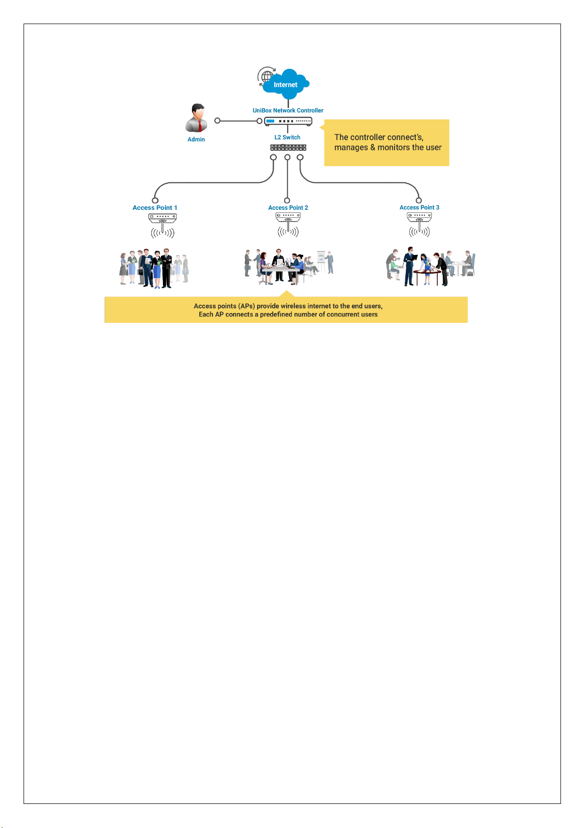
Network Deployment
The diagram below shows a simple deployment scenario for UniBox. It is generally deployed as a
hotspot gateway/controller within a wired or wireless network. In case of a wireless network, several
access points are deployed across the venue to provide adequate signal coverage to the users. These
access points are connected centrally into a POE switch using CAT-5e cables or via Power injectors.
The LAN port of UniBox is plugged into the switch. The access points are usually configured in bridge
mode thus allowing the clients to directly communicate with the UniBox. UniBox is responsible for
assigning IP addresses on the network. It also functions as gateway for all the clients on the network.
The WAN port of UniBox is connected to the WAN circuit. Administrators can place a firewall in
between UniBox and the Internet if desired. Otherwise the WAN port directly connects to the
modem. The WAN settings are programmed in UniBox.
When authentication is enabled, each user needs to provide the correct login credentials in order to
access the Internet. UniBox also performs many other functions like bandwidth control, activity
tracking, caching, content filtering, policy management, etc. In short, UniBox provides administrator
with complete control on the network.
We will go through various scenarios in which Unibox can be deployed. Lets start with Simple Unibox
Deployment Scenarios (UDS1).
UDS1: Unibox Deployment Scenarios 1 – Simple Deployment
Description: An Internet connection to Unibox (WAN Port) via Firewall and then spreads out
internally through different Access Points (AP’s) connected to Switch which is further connected to
Unibox (LAN Port). End User connects to the various Access Points and goes through the Unibox
before they browse the Internet. Diagram below shows detailed deployment of Unibox.
Feature Summary
Networking
This section allows administrators to configure the network settings of UniBox. These settings
are needed to configure the WAN and LAN ports of UniBox and other network related
parameter. Following items can be configured –
1. Port settings – Configure IP settings for WAN and LAN ports.
2. DNS server – configure the primary and secondary DNS servers
3. DHCP server – UniBox runs a DHCP server that issues IP addresses to the clients con-
nected on LAN ports.
4. IP Routes – configure the default and additional IP routes for the Internet traffic
5. NAT – configure network address translation rules to allow port forwarding functions
6. Device Monitoring – configure network devices like access points, switches, router, etc
for monitoring and view the monitoring results
7. SNMP – configure the SNMP agent and traps
8. Dynamic DNS – Configure Dynamic DNS in case Unibox WAN port IP Address is dynamic
and changes frequently. Dynamic DNS helps you to resolve Unibox Hostname even if
your WAN IP address is changing frequently.
Authentication

UniBox provides a redirect function whereby the network user is redirected to a captive
portal before getting access to network resource like Internet. UniBox also provides a local
authentication mechanism to authenticate the users via the RADIUS server. In addition, the
administrator can also configure UniBox to authenticate users via an external RADIUS server.
Bandwidth Management
Bandwidth management is increasingly an important function for public access networks –
wired or wireless. With the explosive growth of online video and rich-media applications,
there is increasing demand for bandwidth and allocating fair bandwidth among users has
become extremely important.
UniBox provides several bandwidth control mechanism and policies to regulate the
bandwidth for each user. This allows administrators to implement fair usage policy among
the users and not allow anyone to hog the bandwidth.
Policies
UniBox implements various policies to control access and bandwidth of the online users.
Administrators can categorize users into various groups and apply the policies on a group
basis. The policies help the administrator implement fair usage, penalize users or limit
bandwidth for each user.
Captive Portal
Captive portal is the first page the users see when she connects to the network. The captive
portal is used to identify the user before the user gets access to the network resource like
Internet. The captive portal can be either hosted on UniBox or it can be loaded from an
external web server. UniBox provides a simple, template-based captive portal design that the
administrators can easily customize with the company branding.
The external captive portal provides administrators much more flexibility and control on the
design and layout of the web page.
Billing
Billing is an important function for Wi-Fi hotspots. UniBox provides a billing engine that gets
seamlessly integrated with the captive portals. Billing can be done either using access
(prepaid) codes or using credit card or PayPal. Administrators can define various billing plans
in the system and offer the billing plans to the guest on the captive portal. Alternatively she
can also generate batch of access codes and distribute them to the end users. Billing section
also generates various reports to track the monthly revenues from the hotspot.
Reporting

Reporting is an important function of UniBox since administrator can retrieve various reports
on usage, revenue and health of the network. The usage reports are used to check the
bandwidth usage, online time and other details of the users. The billing reports provide
information about the revenue generated from the users. The reports can be downloaded in
Excel or PDF format for archiving or further processing.
Subscriber Management
If administrator configures UniBox to use on-board RADIUS server for user authentication
then the user database is stored locally in UniBox database. UniBox provides comprehensive
interface to manage the user information.
Monitoring
UniBox can be used to monitor the health of the wired or wireless network. It provide a
monitoring service that can be used to check whether the network devices like switches,
access points, routers, firewalls, etc are online and the connectivity is intact. UniBox can send
alerts to the administrators in case there is an outage to avoid lengthy downtime for the
network users.
Administration
UniBox provides multiple administration account and each one can be configured with
custom access control rules. This ensures that the administrator can provide adequate access
to UniBox data based on the user privileges
Interfaces
Depending on the model, UniBox provides multiple Ethernet ports. Each UniBox has at least
two Ethernet interfaces – LAN and WAN.
Technical Overview
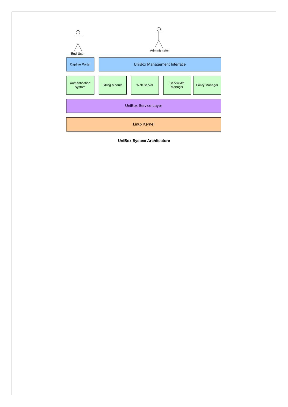
Architecture
UniBox is built on robust and scalable software architecture to ensure a reliable, round-the-clock
performance. UniBox firmware runs on the latest Linux kernel and is compatible with any x86
hardware platform. This provides UniBox a lot of options for deployment. Technically, it is possible
deploy UniBox firmware on a custom designed x86 server to support more than 5000 users.
The software architecture for UniBox is as shown –

Menu Summary
UniBox offers the following menu options to the administrators. Some models may not have the
menu options. Please refer to your admin console to check the menu options available for your
model.
Network
• WAN
• LAN
• VLAN
• Interfaces
• DNS
• VPN
• Monitoring
• DDNS
• IP Routes
• Routing
Wireless
• Heatmaps
• Manage APs
• Clients
Authentication
• Controllers
• Groups
• User Management
• Passthrough
• Portals
• SMS
• MAC Blacklist
• External Services
Control
• Policies
• Content Filter
Advertisement
• Category
• Ads
• Campaign
Billing
• Plans
• Payment Gateway
• Billing Configuration
• Transactions

• Email Templates
• Email Relay
• Vouchers
• PMS
Tools
• Diagnostics Tools
• Remote Syslogs
• User Activity Logs
• Event Logs
• Conntrack Logs
Reports
• Online Users
• User Agents
• SMS
• Social Media
• System
• Usage
• Billing
• Advertisement
• Monitoring
• Automated Reports
Admin
• Accounts
• Profile
• License
• Configuration
• Approvals
• Time
• Reset
• Reboot
• Power Off
• Logs

Getting Started
Before you deploy UniBox, you need to setup your wireless or wired network and need to provision
your Internet connection from the local Internet service provider. UniBox functions as a gateway on
your network so it is deployed between the WAN and LAN portion of your network. You may also
deploy UniBox in the DMZ along with the firewall.
In case of a wireless network, the LAN portion connects to a switch or an access point. The switch
aggregates the traffic from various wireless access points and feeds it into UniBox. UniBox runs a
DHCP server to lease IP addresses to all the clients on the LAN.
The WAN port is usually connected to the modem or router provided by the ISP. In case the network
has a hardware firewall, UniBox is generally deployed after the firewall.
The diagram below shows the rear view of UniBox.
<<UniBox Image>>
The administrator can designate any port for WAN port. Generally the first port (ETH0) is considered
as the default LAN port. All the other ports are not configured. Administrator can configure other
ports as LAN or WAN port depending on their requirements.
The LAN port is accessible at 192.168.100.1 and subnet mask is 255.255.255.0. It runs a DHCP service
so when you connect your laptop the LAN port, it should issue you an IP address in the 192.168.100.x
range.
If you are unable to access the LAN port, please reset the UniBox and retry. Alternatively you can
also configure static IP address on your laptop to connect it to the LAN port.
1. Configure NIC of your Laptop or desktop to have following network configuration (Unibox LAN port
by default has 192.168.100.1 IP address):
a. IP Address: 192.168.110.2
b. Subnet Mask: 255.255.255.0
c. Gateway: 192.168.100.1
2. Connect your Laptop with the network interface you just configured by using standard Ethernet CAT
5 cable (Patch Cord) to the LAN port of Unibox (Refer to screenshot above to know Unibox LAN port)
3. Open your browser (I.E., chrome etc.) and browse the URL http://192.168.100.1
4. Once you load the Unibox User Interface, login with Admin credentials i.e. Username: admin and
Password: admin. Enter the correct captcha value you see on the page.
5. Connect cable coming from your ISP connection to the other port of Unibox.
6. If it is a Static connection you need to have WAN Port configuration details like IP addresses, Subnet
mask and Gateway from your ISP which can be used to configure your Unibox WAN port after it is
set to Static. For Dynamic connection your WAN port gets the network configuration parameters
automatically from your ISP once it is connected. You need to set you WAN to Dynamic mode in that
case. In case of PPPoE connections also, you need to get the WAN port configuration parameters
values from your ISP and then you can set your WAN port to either PPPoE mode before you enter
the configuration parameters.
7. You should now be able to browse internet. Disconnect your laptop and connect Ethernet switch
(Number of Ports on your switch will depend on the number of access points you have and the number of clients you want to connect to your Hotspot).
8. You can now connect either your access points or the client systems to the switch. In case you con-
nect access point, end will connect to Unibox via access points.
9. You can connect you System/Laptop to the switch you just connected, access the Unibox user inter-
face by browsing URL http://192.168.100.1 and continue configuring and customizing Unibox based
on your Hotspot Requirements.
1. DASHBOARD
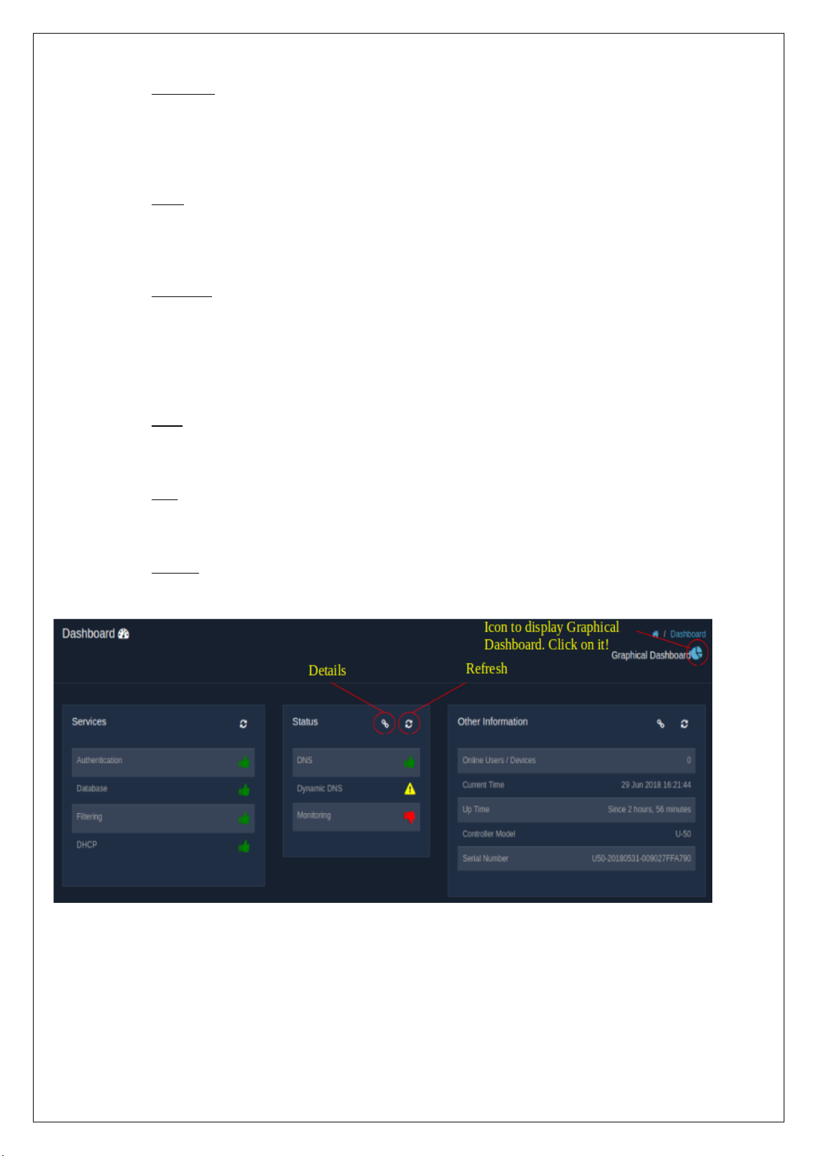
The dashboard gives an overall view of the status of the UniBox. It displays the status of all the important
features present in the UniBox, which might be helpful in discovering any failure in the working of the UniBox
and hence be able to repair and rectify the problems that rise up.
The dashboard represents the information in two ways,
1.1 Tabular Dashboard
The tabular dashboard gives a view of:
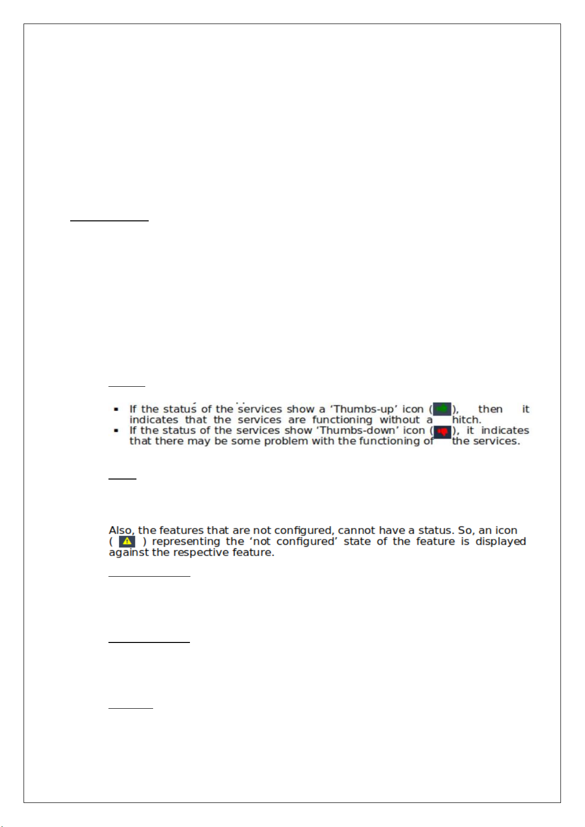
◦ Services – The statuses of all the services provided by the UniBox are displayed. This allows an
admin to know if there are any services that do not function as they are supposed to.
◦ Status – The statuses of all the configured features are displayed. If the status against a feature
shows as a ‘thumbs-up’ icon , then it indicates the proper functioning of the respective feature.
Similarly, if the status of a feature shows the ‘thumbs-down’ icon, then it indicates certain
discrepancies faced by the feature and needs to be looked into.
◦ Other Information – This displays all the information related to the UniBox device. The dashboard
shows the information related to the device, that includes the number of online users or devices,
the current time, the uptime of the system, the controller model and the serial number. To get a
detailed information about the device, click on the details icon provided there. See.
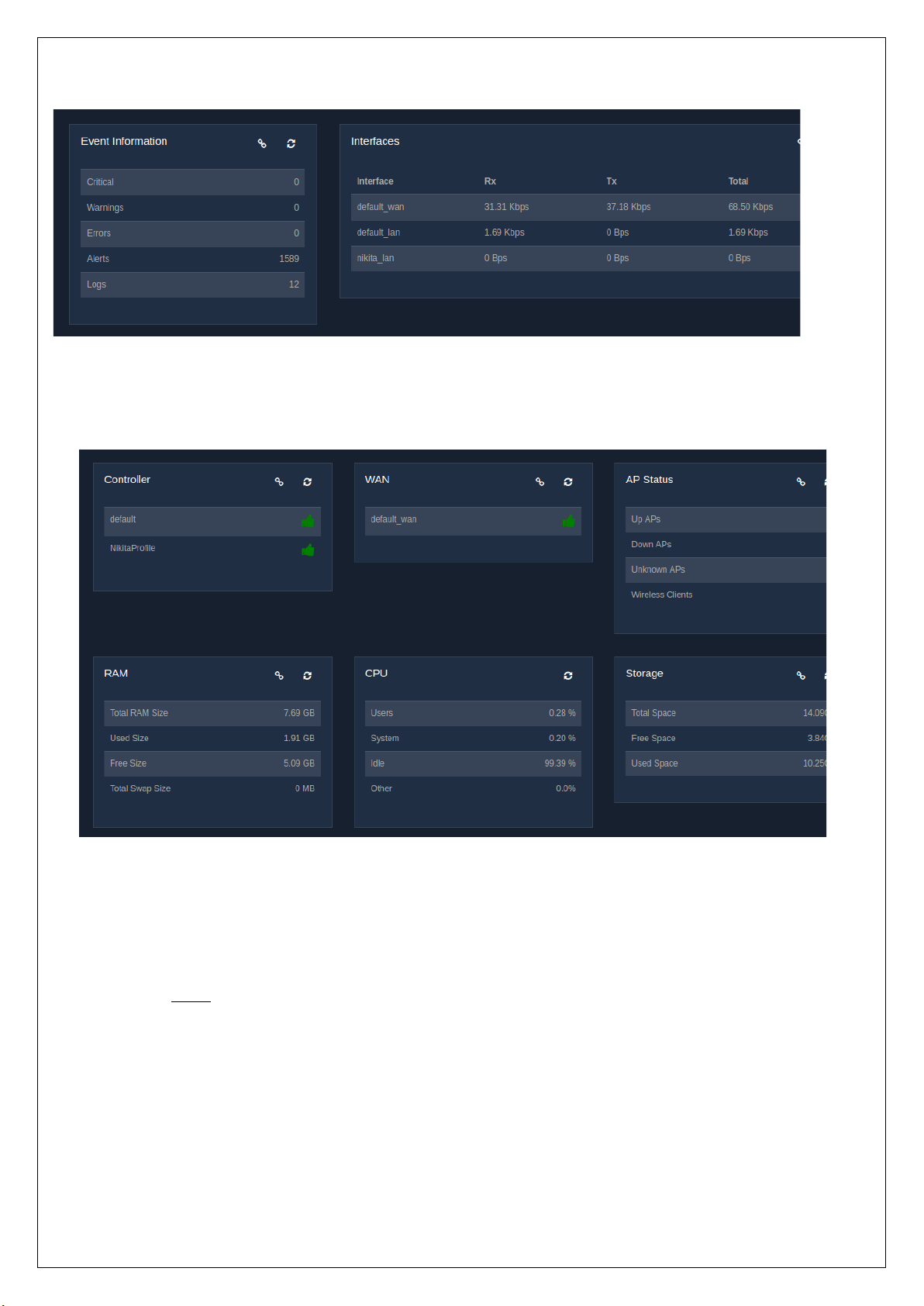
◦ Event Information – This information lets an admin know the number of issues that have been
logged into the system. The events or issues are segregated based on the different types of
severity, namely, critical, warnings, errors, alerts, and logs. To know more about the events, click
on the details icon that has been provided.
◦ Interfaces – All the interfaces configured in the UniBox displayed here, along with their data rates.
The rate at which the packets are received and transferred is displayed along with the total rate.
To see the details of all the profiles, click on the details icon provided.
◦ Controller – This displays all the controllers that have been configured in the UniBox with their
active status. If the status of a controller shows the ‘thumbs-up’ icon, then it indicates the
controller is working perfectly. Similarly, if a controller has issues or problems, then the status is
indicated by the ‘thumbs-down’ icon. Clicking on the details icon will display the detailed
description of the controllers.
◦ WAN – The WAN profiles defined in the UniBox are displayed, giving their current status. The
status of a WAN profile is indicated by a ‘thumbs-up’ icon, if the WAN interface is functioning
properly. At the same time, if the status of a WAN interface is indicated by a ‘thumbs-down’ icon,
then there is a problem or the WAN interface is currently down.
◦ AP Status – This gives an overview on the status of all the APs configured in the UniBox. The AP
status displays the number of access points that are UP or DOWN, the number of unknown APs
and also the number of wireless clients. Unknown APs are the APs that are discovered in the
network but not yet configured. To get a detailed information on the APs, click on the Details icon
provided, which will redirect the admin to the AP management section, allowing him/her to view,
configure, edit, and delete the APs.
◦ RAM – The information on the RAM size of the system is displayed. This shows the total RAM
size, the amount of RAM used, the size of RAM that remains free, and also the amount of RAM
that has been assigned as swap space. To get more information, click on the details icon.
◦ CPU – The status of the processor is displayed. It shows the amount of the processor being
consumed by the users and the system, in percentage. Also the percent of the processor kept idle
and some other information.
◦ Storage – The total storage of the system is displayed along with the amount of space used and
also the remaining free space available.
Fig. 1.1(a)
1.2 Graphical Dashboard
The graphical dashboard gives a statistical view of:
◦ Users – This displays a user versus time graph of connected and online users. The graph displays
the daily statistics of the users on a timely basis.
Fig. 1.1(b)
Fig. 1.1(c)
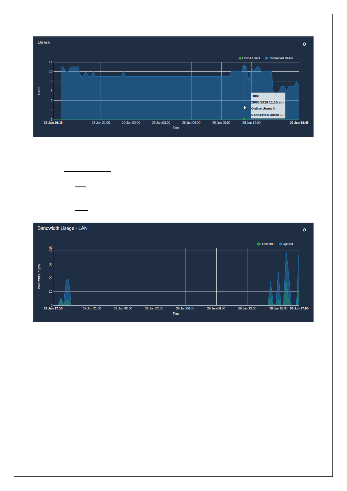
◦ Bandwidth Usage:
▪ LAN – This graph shows the daily bandwidth (download and upload rates) consumed by the
LAN ports over the given time period.
▪ WAN – The bandwidth (upload and download rates) passing through the WAN ports is
represented in a graphical form on a daily basis.
Fig. 1.2.1
Fig. 1.2.2(a)
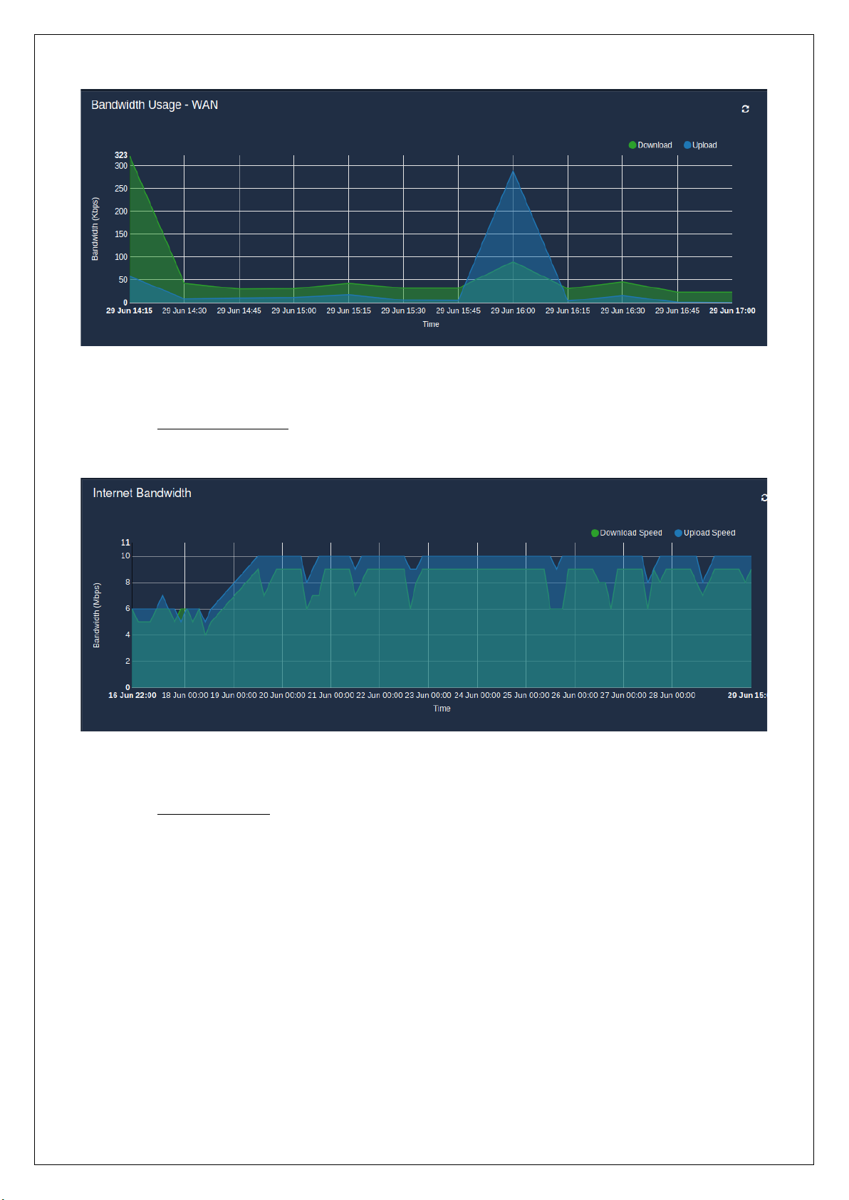
◦ Internet Bandwidth – The graph displays the upload and download speed of the Internet
connection from the ISP, that has been noted down every three hours over 24 hour period.
◦ Port Connections – The number of opened ports over 24 hours is represented in the graphical
form. The opened ports are either destination ports or source ports.
Fig. 1.2.2(b)
Fig. 1.2.3
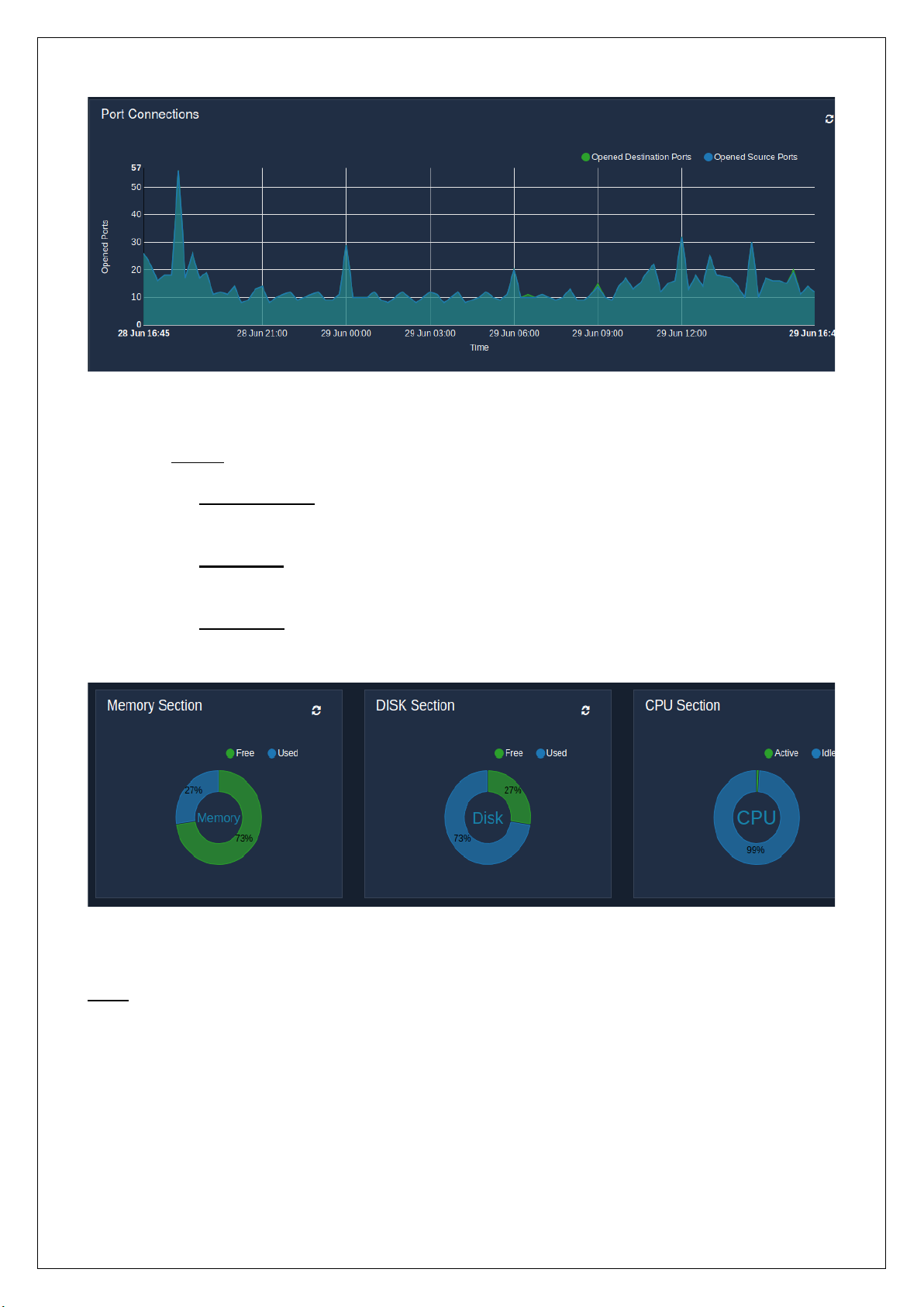
◦ Section:
▪ Memory Section – The pie chart displays the amount of memory used and also the amount
of memory that is free and available.
▪ Disk Section – The amount of disk space used and the disk space available is represented in
the pie chart.
▪ CPU Section – The pie chart represents the percent of the processor that is active and also
the percent of the processor that is idle.
Note: To refresh the status of the different entities, click on the refresh icon provided for each entity.
Fig. 1.2.4
Fig. 1.2.5
2. NETWORK
2.1 WAN
2.1.1 Create / New WAN Profile
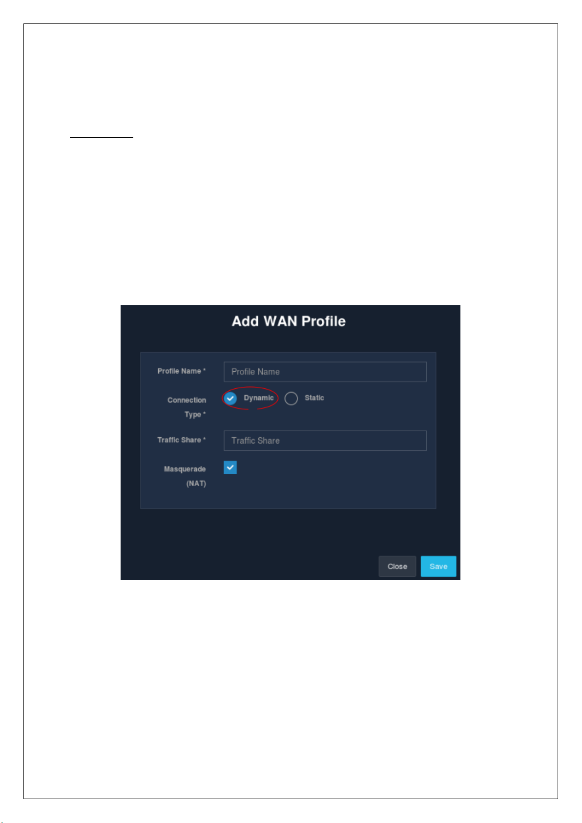
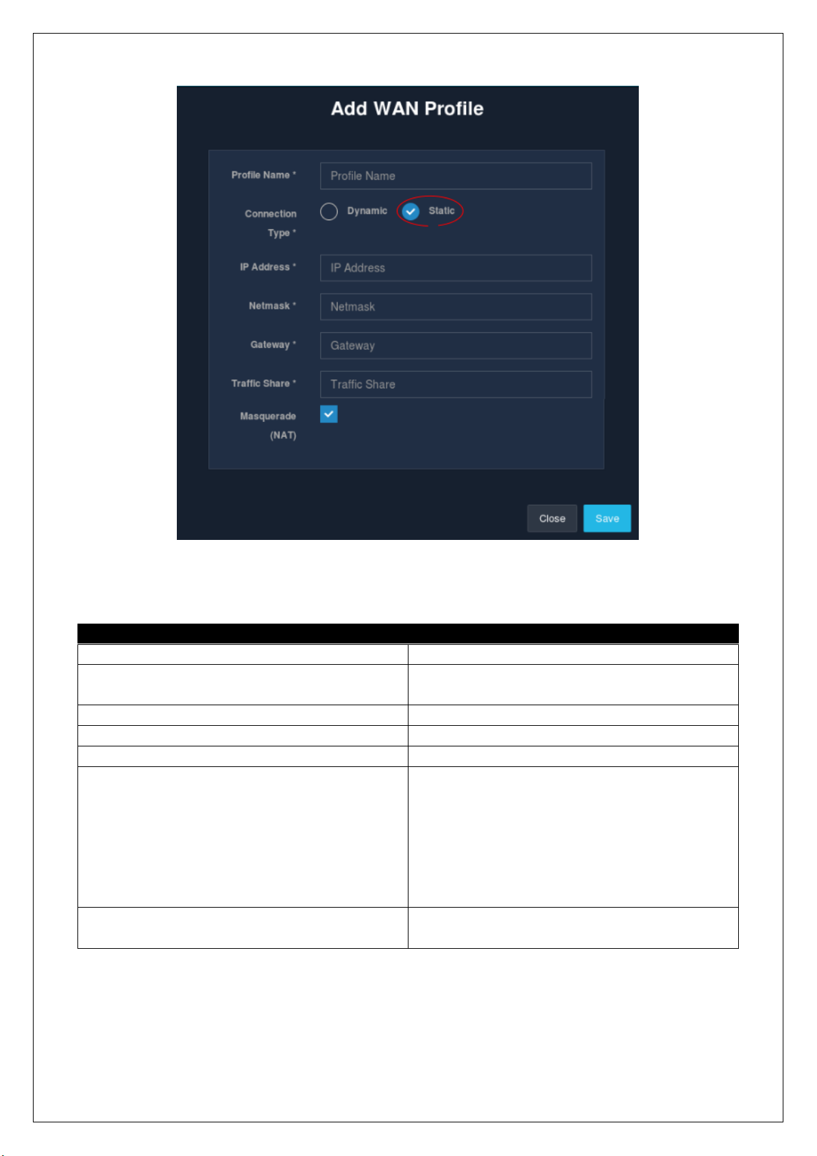
Administrators are allowed to add a new WAN profile. The WAN profile can be either static or dynamic. For
static settings, enter the IP address, subnet mask and gateway IP for connection. The changes will take effect
after the configurations are applied.
To create a WAN profile, go to the ‘WAN’ section under the ‘Network’ module present in the sidebar and click
on the ‘+’ icon. A modal form is displayed that is required to be filled in to create a WAN profile.
Fig. 2.1.1(a)
Fields
Description
Profile Name
Name of the WAN profile.
Connection Type
Select the type of connection, either static or
dynamic.
IP Address
Enter the WAN side IP address.
Netmask
Enter the subnet mask.
Gateway
Enter the gateway IP.
Traffic Share
Enter the share of traffic the WAN connection
should get. The traffic share will decide the
amount of LAN traffic going through the WAN
port. If there is only one WAN profile, then 100%
traffic will go through the WAN port. For multiple
WAN profiles, the value should be less than 100.
Default is 100 percentage.
Masquerade
Tick the check-box if the WAN connection should
masquerade the traffic.
Table 2.1.1
Once the details are filled in, click on the ‘Save’ button. And there! A new WAN profile is created.
2.1.2 List WAN Profile
Fig. 2.1.1(b)
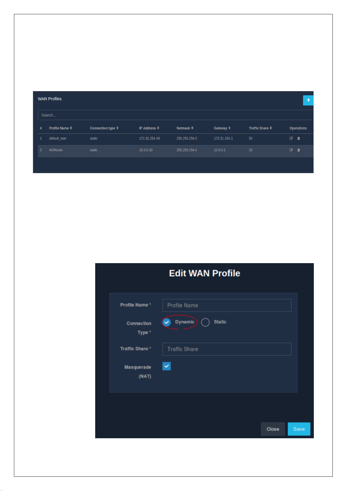
WAN profiles define the internet port settings. The list of all the WAN profiles is
displayed in a table. The list displays the type of connection, assigned IP address, Netmask, gateway IP for the
WAN connection, traffic share along with the profile name. The listing table also contains an ‘Operations’
column wherein there are options to edit or delete WAN profiles.
To view the list of WAN profiles, go to the ‘WAN’ section under the ‘Network’ module in the sidebar.
2.1.3 Edit WAN Profile
An admin can make changes to an existing WAN profile settings. To edit a WAN profile, click on the edit icon
present in the ‘Operations’ column in the ‘WAN’ section of the ‘Network’ module. A modal form, similar to
the one displayed during creation, is displayed to make changes to the already existing settings. Note that if
the settings are incorrect, then the WAN side will become inaccessible. Refer.
Fig. 2.1.2
Fig. 2.1.3 (a)

Click on the ‘Save’ button to apply the changed configurations.
2.1.4 Delete WAN Profile
An admin is given the option to delete an existing WAN profile. To delete a WAN profile, click on the delete
icon in the ‘Operations’ column present in the ‘WAN’ section under the ‘Network’ module.
Click on the ‘Delete’ button to delete a profile.
2.2 LAN
Fig. 2.1.3 (b)
Fig. 2.1.4

2.2.1 Create / Add New LAN Profile
An admin is provided the facility to add a new LAN profile for the UniBox. The LAN profile will be applied to
one of the available ports to create a LAN port on UniBox. The LAN profile will have an option to enable DHCP
service on the LAN port. Configure the LAN IP address of the port along with the subnet mask. Set the number
between 1 and 254 for the start and end of the DHCP pool. Note that the start should be smaller than the
end number.
To create a LAN profile, go to the ‘Network’ module and select the ‘LAN’ section. Then click on the ‘+’ icon. A
window displays a form to be filled in with the information required to add a new LAN profile.
Fields
Description
Profile Name
Name of the LAN profile.
IP Address
Enter the IP address of the LAN port.
Net Mask
Enter the subnet mask.
Enable DHCP
Enable DHCP service on the LAN port.
Pool Start
Enter the starting IP of the DHCP pool.
Pool End
Enter the ending IP of the DHCP pool.
Lease Interval
Enter the DHCP lease interval in seconds.
Fig. 2.2.1

Domain Name
Enter the domain name for the DHCP service.
Table 2.2.1
Click on the ‘Save’ button to apply the information and create a LAN profile.
2.2.2 List LAN Profile
All the LAN profiles configured on the UniBox are listed down in a tabular form. The list displays the profile
name, IP address of the LAN port, subnet mask, and whether the LAN port has enabled DHCP services or not.
The listing table also contains an ‘Operations’ column where the options to edit or delete profiles are
available.
To view the list of LAN profiles, go to the ‘LAN’ section in the ‘Network’ module.
2.2.3 Edit LAN Profile
The edit option allows an admin to edit or make changes to an already existing LAN profile. While changing
the configurations of the profiles, make sure to change the DHCP pool accordingly.
To edit a LAN profile, click on the edit icon in the ‘Operations’ column present in the
‘LAN’ module. All the clients connecting to the LAN port will be issued new IP addresses.
Fig. 2.2.2
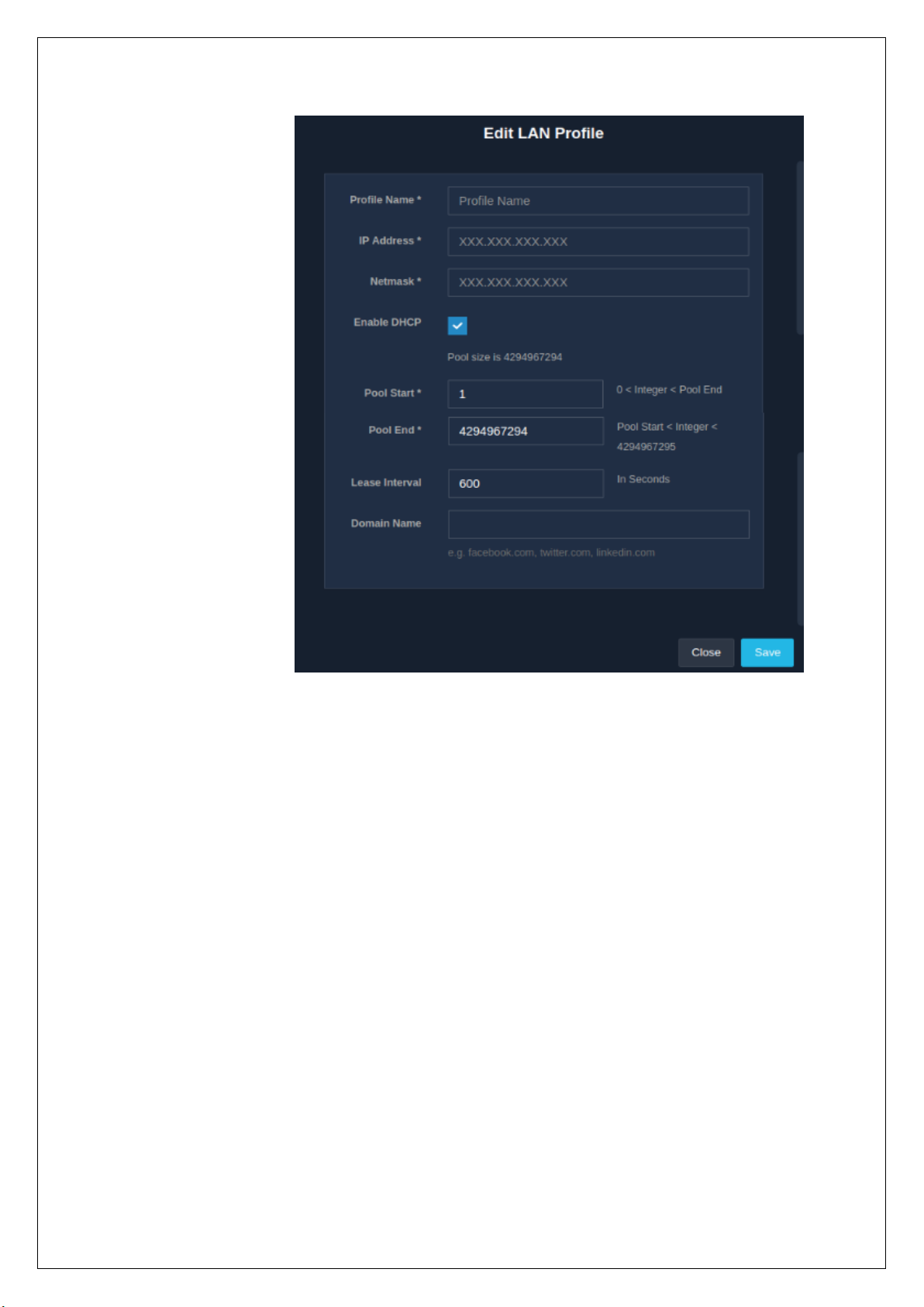
Click on the ‘Save’ button to update and apply the new settings. When the settings are changed, all the online
users will have to relogin.
2.2.4 Delete LAN Profile
An admin can delete a configured LAN profile. LAN profiles can only be deleted once they are dissociated
from the LAN interface. To dissociate or remove the LAN profile from the LAN interface, refer to the Interface
section.
To delete LAN profiles, click on the delete icon in the ‘Operations’ column present in the ‘LAN’ section of the
‘Network’ module. A message window appears to confirm the delete action about to be performed.
Fig. 2.2.3

Click on the ‘Delete’ button to surely delete the LAN profile.
2.3 VLAN
2.3.1 Create / Add New VLAN Profile
VLAN are virtual subnet created for dividing network into logical subnets and isolating the traffic on the
physical network.
Use this feature to define a VLAN profile in UniBox. The profile can be applied to a physical or virtual port and
all the traffic following from the port will be tagged with the VLAN tag(s). Administrators can define a fixed
single VLAN tag or a range of VLAN tags. In case of a range of VLANs, the start ID and end ID must be specified.
To create a VLAN profile, go to the ‘Network’ module and in the ‘VLAN’ section, click on the ‘+’ icon. A modal
form is displayed where the information required to create a VLAN profile are to be filled in. The fields in the
form change with the change in the types of VLAN:
• Fixed: It refers to a single VLAN tag.
• Range: It refers to the wide range of VLAN tags that can be defined.
Fig. 2.2.4

Fields
Description
Profile Name
Name of the VLAN profile.
VLAN Type
Select one of the VLAN type, either Fixed or
Range.
VLAN ID
Enter the VLAN ID for single or fixed VLAN.
Start ID
Enter the start of VLAN ID for VLAN of the range
type.
End ID
Enter the end of VLAN ID for VLAN of the range
type.
Table 2.3.1
Finally, click on the ‘Save’ button to save the configurations and create a VLAN profile.
2.3.2 List VLAN Profile
All the VLAN profiles configured in UniBox are displayed in a list. The list displays the profile name, VLAN type,
VLAN ID, end Id and start Id. The listing table also contains an ‘Operations’ column, which provides the options
to edit or delete profiles.
Fig. 2.3.1

An admin can view the list of VLAN profiles by going to the ‘Network’ module and selecting the ‘VLAN’ section.
2.3.3 Edit VLAN Profile
The edit option allows an admin to make changes to the configurations of an already existing VLAN profile.
To edit a VLAN profile, click on the edit icon in the ‘Operations’ column present in the ‘VLAN’ section under
the ‘Network’ module. A modal form is displayed to make the required changes to the configuration.
2.3.4 Delete VLAN Profile
Fig. 2.3.2
Fig. 2.3.3
The delete option allows an admin to delete an existing VLAN profile. It is important to disassociate the VLAN
profile from the port before deleting the VLAN profile.
To delete a VLAN profile, go to the ‘Network’ module and then select the ‘VLAN’ section. Click on the delete
icon present in the ‘Operations’ column against the profile that needs to be deleted.
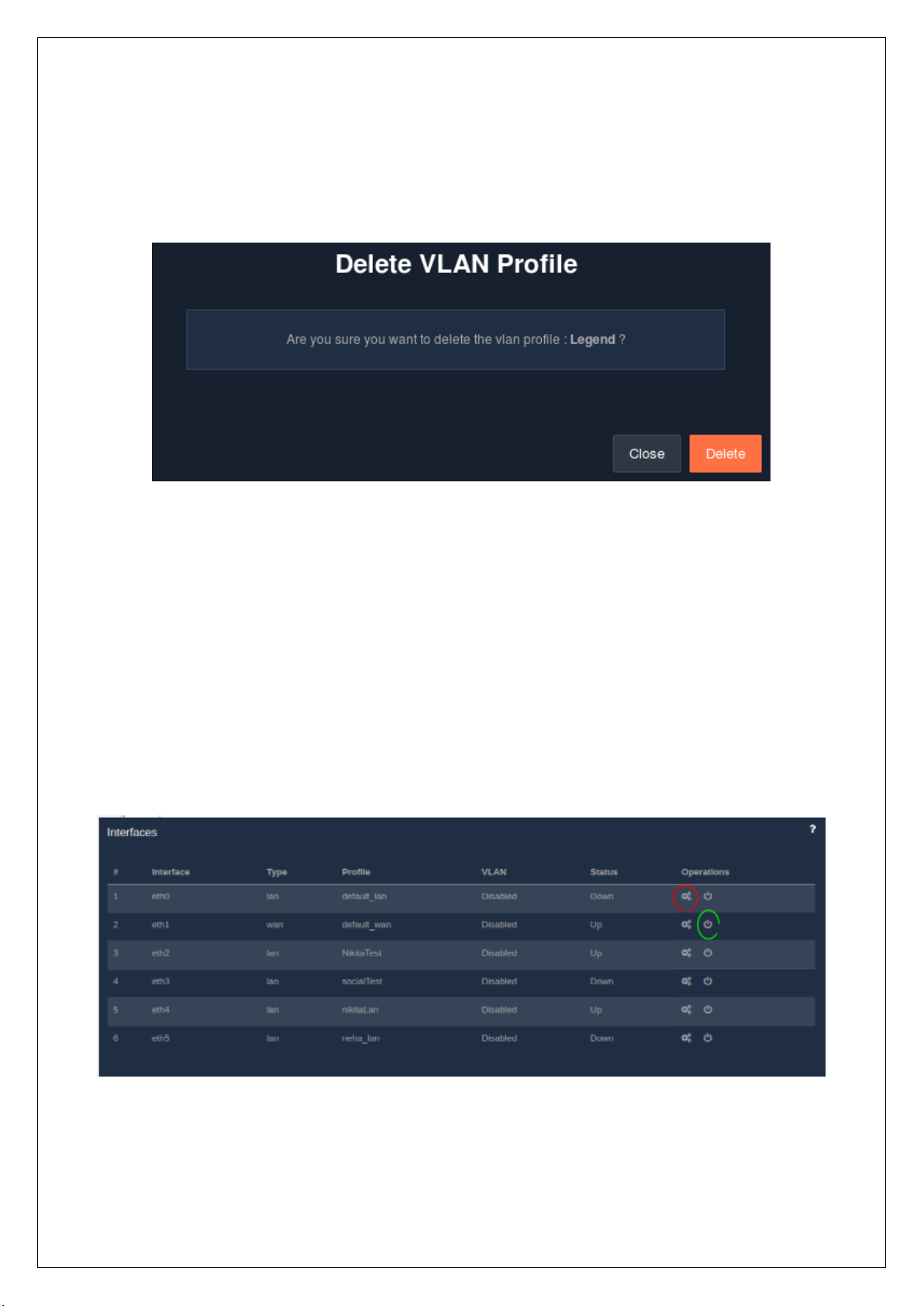
2.4 Interfaces
2.4.1 List Interface
All the available physical network interfaces on the UniBox hardware are listed down in a table. An admin can
assign any LAN or WAN profile to the interfaces. In the list, each interface is labelled as ‘eth#’ where # is the
number of the interface like eth0, eth1, etc. The list displays the port number, type of profile (LAN or WAN),
name of the assigned profile, VLAN status (enabled or disabled) and the status of the port. If the connection
is active, the port will appear UP else DOWN.
To view the list of interfaces, go to the ‘Network’ module followed by the ‘Interfaces’ section. The listing table
also contains a column, named ‘Operations’, which provides the options to configure or reset interfaces.
2.4.2 Configure Interface
Configure
Reset
Fig 2.3.4
Fig 2.4.1

An admin is facilitated with the feature to configure the network interface. The admin can assign the interface
to either LAN or WAN profile. If the the interface is assigned to a LAN profile, the interface will function as
LAN port. If the interface is assigned to a WAN profile, the interface will function as WAN port. The admin can
also enable VLAN tagging by enabling the VLAN profile and select VLAN profile from the list in the drop-down
menu.
To configure an interface, go to the ‘Network’ module and then the ‘Interface’ section. The listing table
contains an ‘Operations’ column, which has one of the options as configure. Click on the configure icon. A
window drops-down, displaying a form to fill in the configuration details.
Fields
Description
Interface Name
Name of the network interface. This field is noneditable.
Interface Type
Select whether the interface type is WAN or LAN.
Network Profile
Select the LAN or WAN profile to associate with
the interface.
Enable VLAN
If enabled, the interface will tag the traffic with
the assigned VLAN tag.
VLAN Profile
Select the VLAN profile from the list.
Table 2.4.2
Click on the ‘Save’ button after all the details are entered in, to apply the configurations.
Note: For multi-WAN setup, admin will have to configure at least two WAN profile on two separate
interfaces.
Fig 2.4.2

2.4.3 Reset Interface
The reset feature allows an admin to remove all the profiles associated with the network interfaces. The
interface will be available for another configuration once the profile is removed. All the devices connected to
the interface will lose their connectivity to the UniBox once the profile is removed.
To reset an interface, click on the reset icon in the ‘Operations’ column present in the ‘Interfaces’ section. A
message window slides down to confirm the reset action.
2.5 DNS
2.5.1 Create DNS
An admin is allowed to add a new DNS server. All devices connected to the UniBox will use the DNS servers
configured in this section.
To create a DNS server, select the ‘DNS’ section under the ‘Network’ module. Then click on the ‘+’ icon, a
window pops-up to get the DNS server’s IP address.
Fig 2.4.3
Fig 2.5.1
Field
Description
DNS Server IP
Enter the IP address of the DNS server.
Table 2.5.1
Once the DNS server IP is entered, click on the ‘Save’ button.
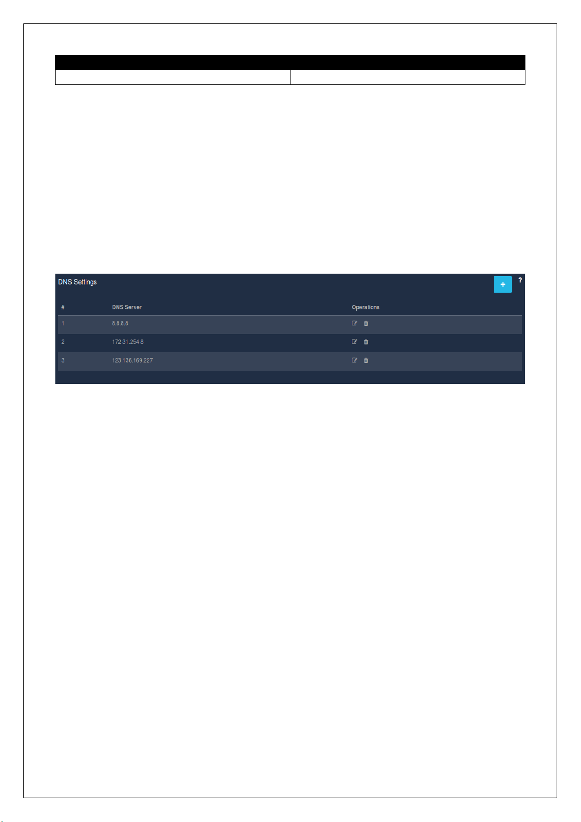
2.5.2 List DNS
All the DNS servers configured in the UniBox are listed down in a table. The DNS servers will be used in the
order they were added.
To view the list of the DNS server, go to the ‘Network’ module followed by the ‘DNS’ section. A listing table
displays the configured DNS servers and also consists of an ‘Operations’ column, which provides the options
to edit or delete DNS servers.
2.5.3 Edit DNS Server
The edit feature serves an admin with an option to make changes to an existing DNS server settings.
To edit a DNS server, click on the edit icon made available in the ‘Operations’ column in the ‘DNS’ section
present in the ‘Network’ module. A window slides down to make change to the DNS server’s IP. Refer.
Fig 2.5.2

Once the required changes are made to the server IP address, click on the ‘Save’ button to save the
configuration for the changes to take effect.
2.5.4 Delete DNS Server
To delete a DNS server, all an admin has to do is, click on the delete icon in the ‘Operations’ column present
in the ‘DNS’ section of the ‘Network’ module. A message window appears asking to confirm the delete action.
Click on the ‘Delete’ button to surely delete the DNS server.
2.6 VPN
An admin is facilitated with the feature which allows him/her to run a VPN server inside UniBox. This feature
is beneficial if the admin wants to offer VPN access into the enterprise network. The VPN can run in two
modes:
• Bridges (TAP):-
◦ It behaves like a real network adapter, except that it is a virtual adapter.
◦ Can transport any network protocols (IPv4, IPv6, Netalk, IPX, etc.).
◦ Works at layer 2, which means that the Ethernet frames are passed over the VPN tunnel.
Fig.2.5.4
Fig 2.5.3

◦ Can be used in bridges.
• Router (TUN):-
◦ It has a lower traffic overhead, transports only traffic which is destined for the VPN client.
◦ Transports only layer 3 IP packets.
▪ Drawbacks of TUN -
• Broadcast traffic is not normally transported.
• Can only transport IPv4 (OpenVPN 2.3 adds IPv6)
• Cannot be used in bridges.
The VPN server will require a signed SSL certificate for authenticating the client. By default, UniBox comes
with a signed SSL certificate, but the client can upload their own SSL certificate in UniBox.
To configure an on-board VPN server, go to the ’Network’ module followed by the ‘VPN’ section. A page
displays a form to gather all the details required to configure a VPN server.
Fields
Description
Enable VPN server
If enabled, the VPN server will run the UniBox and
will accept remote clients.
Port Number
Enter the port number for VPN server.
Tunnel Protocol
Select the tunnel protocol, either TCP or UDP.
Server Mode
Select the VPN server mode, either TAP or TUN.
Fig.2.6

IP Address
Enter the IP address of the VPN server. Clients will
connect to this IP from remote sites.
Netmask
Enter the subnet mask.
LAN Profile
Select the LAN profile on which the VPN server
will run.
Advanced Options
Tick-off the checkbox to enable advanced options.
Public Server Certificate
Enter the public server certificate.
CA Certificate
Enter the CA certificate.
Private Server Key
Enter private server key.
Enable TLS Authentication
If enabled, TLS authentication is enabled.
TLS Auth Key
Enter the authentication key for TLS
authentication.
Masquerade (NAT)
Tick the check-box for the server to enable
masquerading of the packets.
Force Default Route
Tick the check-box if the server should force the
traffic on default IP route.
Table 2.6
When all the details are carefully filled in, click on the ‘Submit’ button.
2.7 Monitoring
The UniBox monitors each configured device periodically, then alerts the admin if there is an outage. UniBox
uses the MAC address of the device for monitoring as the IP address of the device may change if the device
is on a dynamic IP. Also, MAC address monitoring is more reliable. The admin is required to enter the MAC
address of the interface that will be connected to the UniBox for monitoring.
2.7.1 Create / New Monitoring Device
An admin is facilitated with the services that allows him/her to configure a new device for monitoring. If the
UniBox is used within a wireless network, then admin can configure the devices in UniBox for monitoring.
UniBox will check the status of all devices periodically and will send email alerts if any of them are down. The
UniBox can monitor devices, both on LAN and WAN side. LAN side devices are monitored using their MAC
address while the WAN side requires the IP addresses.
UniBox runs a monitoring process that will periodically check the status of all access points. Admin can
configure one or more email addresses for notification.
To add a new monitoring device, go to the ‘Network’ module followed by the ‘Monitoring’ section. Then, click
on the ‘+’ icon, a modal form appears to gather information required to add a new device for monitoring.
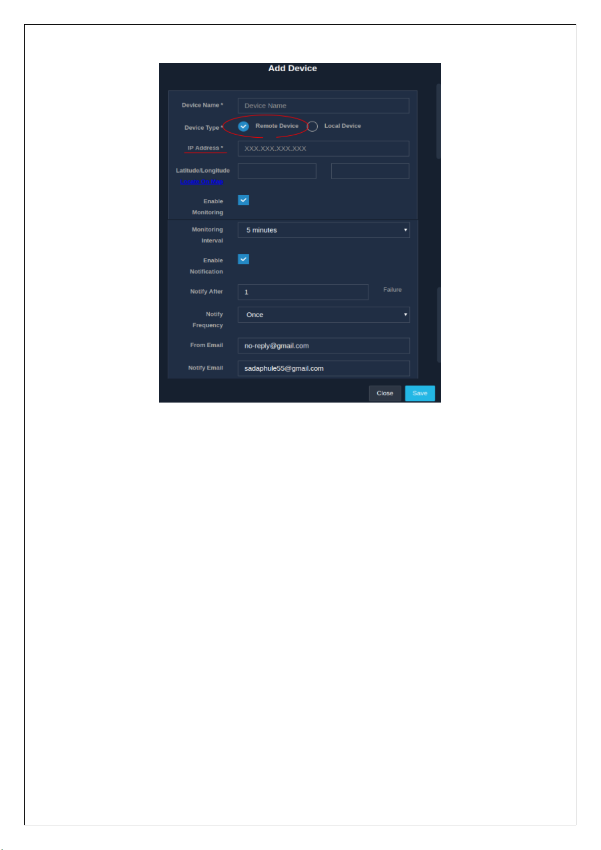
Fig 2.7.1(a)

Fields
Description
Device Name
The name of the device to be monitored. Enter a
name that will make identifying the device easier.
Device Type
Select the device type, either remote or local. For
devices that are:
• Remote – Enter the public IP address.
• Local – MAC address is compulsory.
IP Address
Enter the Public IP address of the remote device
to be monitored.
MAC Address
The MAC address of the local device to be
monitored.
Latitude/Longitude
The latitude and longitude coordinates of the
device to be monitored, (if available), for plotting
the AP on the map.
Enable Monitoring
Ticking off the check-box enables the device to be
monitored.
Monitoring Interval
Select the interval for monitoring the device from
the options available in the drop-down menu.
UniBox will monitor the device after the
configured interval.
Fig 2.7.1 (b)

Enable Notification
If ticked-off, the UniBox will email the UP or
DOWN status of the device to the configured
email addresses.
Notify After
Enter a number which indicates the number of
failures after which the notification will be sent.
Notify Frequency
Indicates whether the notification is sent once or
multiple times. Default: Once.
From Email
Email address (only one) from which the
notification will be sent.
Notify Email
Email addresses to which the notifications will be
sent to. Multiple email addresses should be
separated by comma.
Table 2.7.1
Click on the ‘Save’ button to apply all configurations entered and monitor a device.
2.7.2 List Monitoring Device
The table provides an admin with a list of all the devices configured for monitoring.
The list provides the status of the devices configured, whether they are UP or DOWN, along with the name
of the device, IP address, MAC address, device vendor, monitoring status (enabled or disabled) and the last
monitored time. Also the listing table contains the ‘Operations’ column, which provides the services of edit
and delete.
To view the list of all the added monitoring devices, go to the ‘Network’ module followed by the ‘Monitoring’
section. The list will be visible along with the option to search devices based on the status, the fields (device
name, IP address or MAC address) and the value of the selected criterion.
2.7.3 Edit Monitoring Device
Configurations
Fig 2.7.2
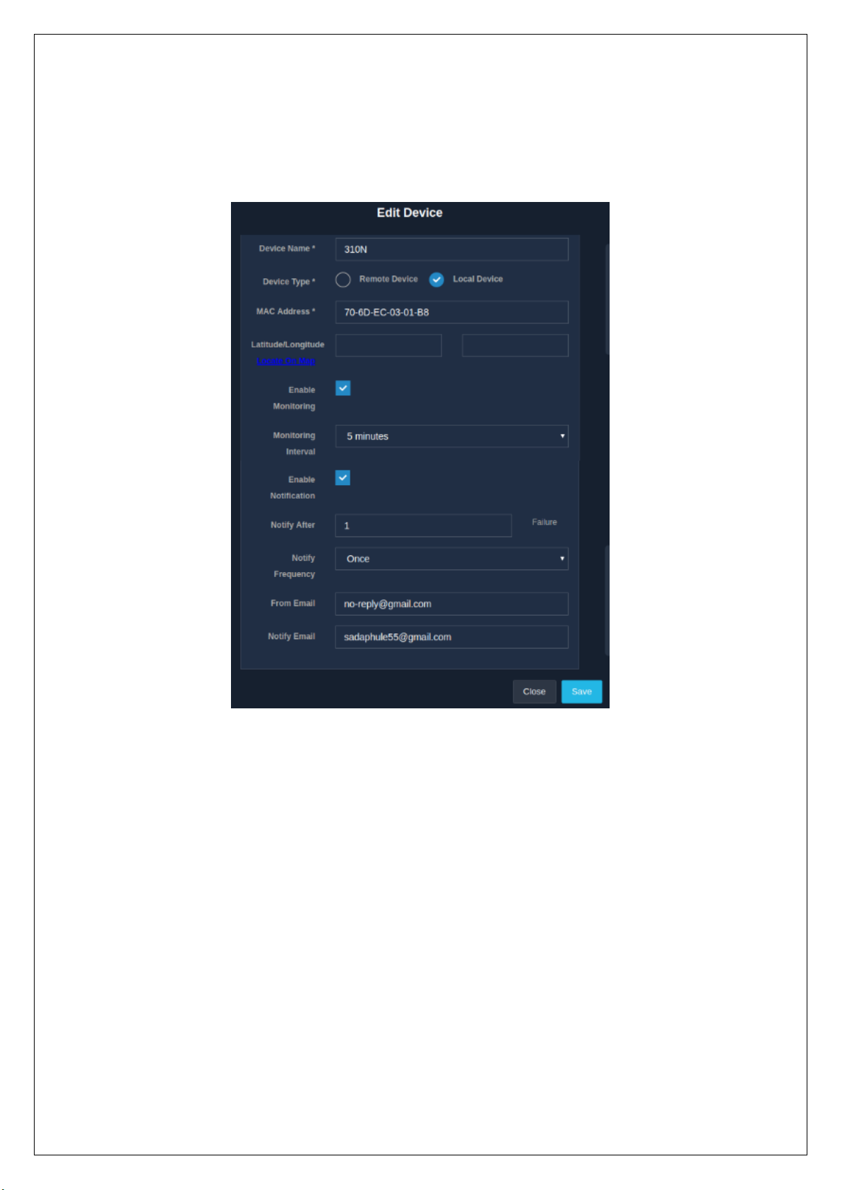
An admin is allowed to make changes to the information about an already existing monitoring device.
To edit the device information, click on the edit icon in the ‘Operations’ column present in the ‘Monitoring’
section of the ‘Network’ module. A modal form with the previously entered information is displayed for all
the necessary changes to be made. Refer
Once the necessary changes are made, click on the ‘Save’ button to apply the changes.
2.7.4 Configure Monitoring Device
An admin is provided with the facility to specify the default configuration of the monitoring devices. If multiple
monitoring devices are added, it is advisable to set the default monitoring settings before adding the devices.
This will ease the chore of configuring the notification settings of each device.
To set the default notification settings, select the ‘Monitoring’ section in the ‘Network’ module. Then click on
the configuration icon, which displays a form to configure the devices.
Fig 2.7.3

Fields
Description
Monitoring Interval
The default time interval for monitoring the
device.
Notify After Failure
This setting will send notifications after the
configured successive failures.
Frequency
Indicates whether the email notification is to be
sent once or multiple times.
From Email
The email address from which the email
notification will be sent.
Notify Email
The email address to which the email notification
will be sent to. Multiple email addresses should
be separated by commas.
Table 2.7.4
Once the configurations are entered in, click on the ‘Save’ button to apply and set the said configurations.
2.7.5 Delete Monitoring Device
To delete a device from the monitoring list, tick-off the checkbox in the ‘Operations’ column present in the
‘Monitoring’ section of the ‘Network’ module. When a check-box is ticked-off, the delete icon appears above
the listing table. Clicking on the delete icon displays a message window asking to confirm the delete action.
Fig 2.7.4

Click on the ‘Delete’ button to delete the device from the monitoring list.
Note: Multiple devices can be deleted at a time by ticking-off the checkboxes of those devices that are to
be deleted.
2.8 DDNS
An admin is allowed to configure the Dynamic DNS client in the UniBox. Configuring Dynamic DNS client will
help an admin to access the UniBox from public network, even when the UniBox WAN IP is set on dynamic
mode and the IP changes frequently. DDNS client on UniBox will periodically update the host name record
stored at the dynamic DNS server with WAN port settings. Admin can access the UniBox from a public network
using the specified DDNS hostname.
To configure a Dynamic DNS client, go to the ‘DDNS’ section in the ‘Network’ module. A page displays a form
meant to collect the details required to configure the DDNS client.
Fig 2.7.5

Fields
Description
Enable Dynamic DNS
Ticking-off the check-box will enable the Dynamic
DNS client in UniBox. This client is responsible for
updating the UniBox WAN IP to the DDNS server.
DDNS Provider
Select the Dynamic DNS service provider from the
drop-down list. At present, two Dynamic DNS
providers are supported:
• Dyn DNS
• no-ip DNS
An admin has configure his/her own account
from these providers.
DDNS Server
Enter the server name of the Dynamic DNS
provider.
Username
Enter the username of the already created
account on Dynamic DNS server.
Password
Enter the password of the already created
account on the Dynamic DNS server.
DDNS Service
Select the Dynamic DNS from the drop-down
menu, either free or customer (paid).
Host Name
Enter the fully qualified hostname to be updated
against the IP address in the Dynamic DNS server
records. The settings should be obtained from the
DDNS provider.
Use Secure Updates
If ‘Yes’, DNS record updates are sent to the DDNS
server over secure (HTTPS) channel.
Fig 2.8

Use External IP Check
If ‘Yes’, the gateway public (WAN) IP is obtained
and used for DNS updates. It is used in private
network settings.
Table 2.8
Once all the details are filled in, click on the ‘Submit’ button to save all the configurations of the DDNS.
2.9 IP Routes
2.9.1 New IP Routes
An admin is allowed to create a new IP route on the UniBox for both inbound as well as outbound traffic. The
IP route will decide how the packets are routed from the UniBox to other hosts or networks. The IP routes
can be defined for a specified host or network. If defined for a specific host, then UniBox will use the specific
rule to route the IP packets to that host.
To create or add a new IP route to UniBox, go to the ‘IP Routes’ section in the ‘Network’ module. Then click
on the ‘+’ icon, where a modal form is displayed to collect the information required to add a new IP route.
Fields
Description
Name
Name of the IP route.
Interface
WAN or LAN interface on which the rule will be
applied.
Destination IP
Enter the final destination. If the type is host, then
destination is the specific IP of host or else the
Fig 2.9.1

netmask and destination will determine the
destination network.
Netmask
Enter the subnet mask for the destination IP.
Gateway IP
The IP address of the gateway that is the
middleware between the source and destination.
Metric
Cost of the path to the destination. The cost is
based on various factors like bandwidth, number
of hops, etc.
Table 2.9.1
Click on the ‘Save’ button to apply the configurations and add a new IP route.
2.9.2 List IP Route
All the IP routes configured in the UniBox are displayed in the listing table. The default IP route will display
the route available to all UniBox clients. This cannot be edited since it is auto-generated when the WAN port
settings are set. An admin can add additional IP routes depending on the network requirements.
To view the list of all the IP routes, go to the ‘Network’ module followed by the ‘IP Routes’ section. The listing
table contains the name of the route, the interface on which the route is configured, the destination IP,
netmask, the gateway IP, metric and also the ‘Operations’ column, which contains the options to edit and
delete.
2.9.3 Edit IP Route
The edit feature allows an admin to make changes to an already existing IP route. The interface defines the
network on which the route applies.
To edit an IP route, go to the ‘Network’ module followed by the ‘IP Routes’ section. Then click on the edit icon
that is present in the ‘Operations’ column. When clicked, a modal form is displayed to edit the information
that was previously given while adding the IP route.
Fig 2.9.2

Click on the ‘Save’ button to set and apply the changes made.
2.9.4 Delete IP Route
To delete the IP route, click on the delete icon present in the ‘Operations’ column in the ‘IP Routes’ section
of the ‘Network’ module. A message window pops to confirm the delete action.
Click on the ‘Delete’ button to remove the IP route.
2.10 Routing
2.10.1 Post Forwarding
Fig 2.9.3
Fig 2.9.4
The NAT rules are used by the UniBox to forward either incoming or outgoing packets to specific hosts within
the LAN network. The NAT rules can be configured for different ports. For example, to access a client inside
the UniBox network, there is a need to configure a port forwarding NAT rule. The NAT rules can be configured
for both TCP and UDP packets.
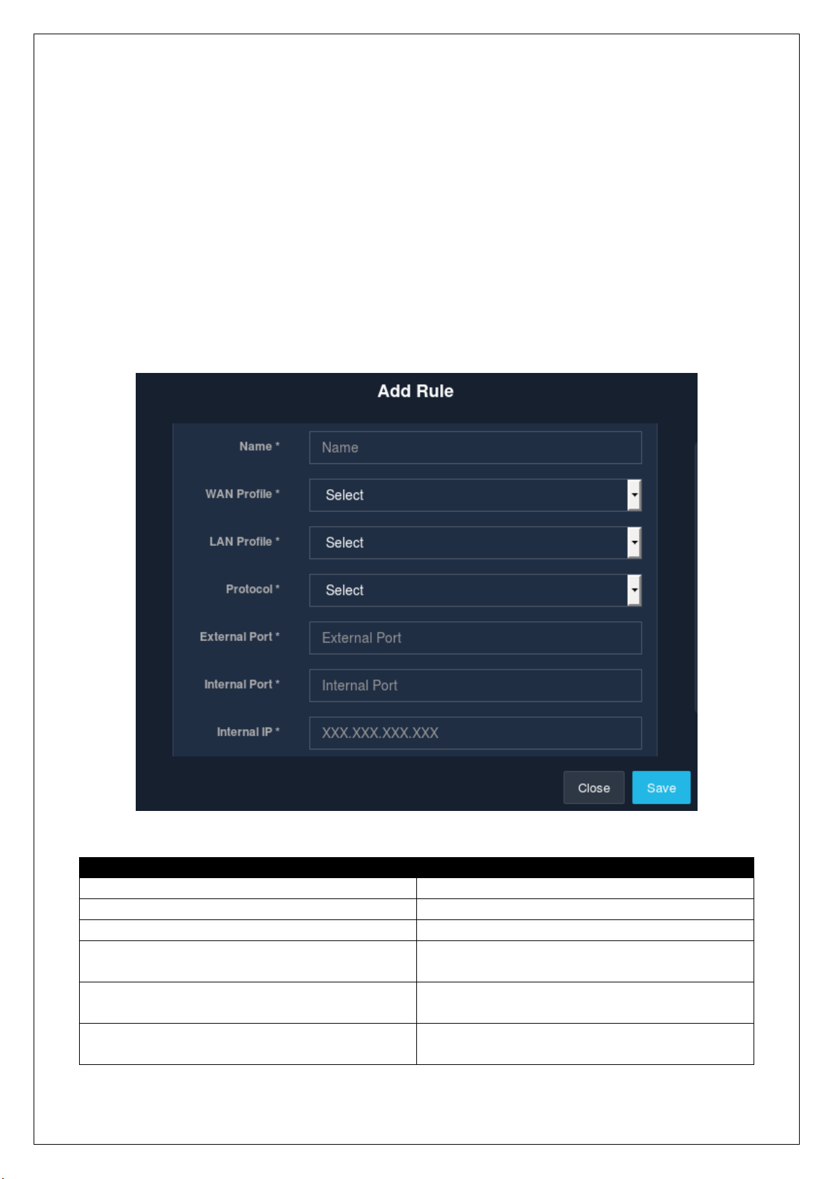
2.10.1.1 New Port Forwarding
An admin is allowed to add a new Network Address Translation (NAT) rule to UniBox. By default, UniBox will
block all the traffic from the WAN port to the LAN port. A NAT rule will allow an admin to selectively allow
specific port traffic to pass from the WAN port to LAN port based on the way the rule is defined.
To add a new NAT rule, go to the ‘Network’ module followed by the ‘Routing’ section. Then go to the ‘Post
Forwarding’ sub-section and click on the ‘+’ icon. A modal window is displayed to collect the information
required to add a new rule.
Fields
Description
Name
Enter the name of the NAT rule.
WAN Profile
Select the WAN profile.
LAN Profile
Select the LAN profile.
Protocol
Select whether the rule applied to TCP or UDP or
both the traffic.
External Port
Enter the port number (1-65535) that will be
forwarded to an internal port.
Internal Port
Enter the port number (1-65535) to which the
traffic will be forwarded.
Fig 2.10.1.1

Internal IP
Enter the IP address of the client inside the LAN
network.
Table 2.10.1.1
Click on the ‘Save’ button to save and apply the newly defined rule.
2.10.1.2 List Port Forwarding
A table lists down all the NAT port forwarding rules defined in the UniBox. The listing table displays the name,
WAN profile, LAN profile, protocol, external and internal port, along with the private IP address of the client.
The table also contains the ‘Operations’ column providing the edit and delete options.
To view the list of all the NAT rules, select the ‘Post Forwarding’ sub-section from the ‘Routing’ section in the
‘Network’ module.
2.10.1.3 Edit Port Forwarding
To modify or make changes to an already existing NAT rule, click on the edit option present in the ‘Operations’
column in the ‘Post Forwarding’ sub-section of the ‘Routing’ section, found in the ‘Network’ module. A modal
form displays all the previously acquired information to make the necessary changes.
Fig 2.10.1.2

Click on the ‘Save’ button to set and apply all the changes made.
2.10.1.4 Delete Port Forwarding
Deleting a NAT rule is quite simple. Click on the delete icon present in the ‘Operations’ column in the ‘Post
Forwarding’ sub-section of the ‘Routing’ section. A window displays a message to confirm the delete action.
Click on the ‘Delete’ button to delete a NAT rule.
2.10.2 Group Routing
2.10.2.1 New Group Routing Rules
Fig 2.10.1.3
Fig 2.10.1.4

An admin is facilitated with the feature to configure a group routing rule in UniBox. The rule allows a specific
group of authenticated users to access the LAN segment. Usually the rule is used to route the traffic to the
server pool or the restricted subnets for a group of users.
To add a new group routing rule, go to the ‘Network’ module and select the ‘Routing’ section, followed by
the ‘Group Routing’ sub-section. Then, click on the ‘+’ icon which displays a modal form to collect information
required to add a new group routing rule.
Fig 2.10.2.1 (a)

Fields
Description
Name
Enter the name of the rule.
Source*
Select the source, either LAN or controller. If the traffic
from LAN side needs to access a specific LAN profile,
then select the LAN interface source.
Controller
Select the controller profile on which the rule will be
configured.
User Group
Select the user-group whose members will use the
routing rule.
LAN Profile
Select the source LAN segment for the user-group.
Destination LAN Profile
Select the destination LAN segment for the group of
users.
Is Active
Once the check-box is ticked-off, the rule will be applied
effectively.
Table 2.10.2.1
Fill in the form with all the details, then click on the ‘Save’ button to add and apply the new rule.
Note: Depending on the source selected, that is either LAN or controller, the fields will change respectively.
2.10.2.2 List Group Routing Rules
All the routing rules configured for a specific group of users are listed down in a table. The routing rules will
allow only a certain group of authenticated users to access the network segment. These settings are generally
done to provide selective access to a subnet.
Fig 2.10.2.1 (b)
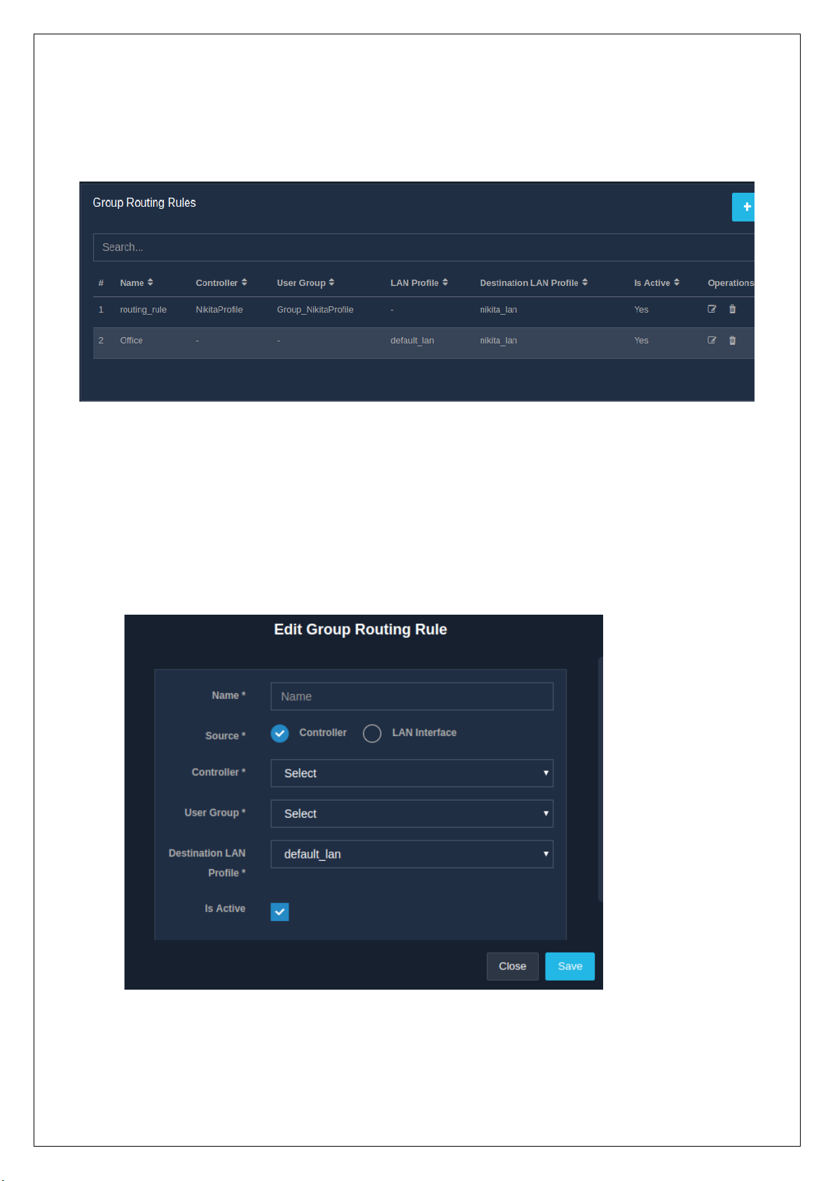
To view the list of group routing rules, go to the ‘Network’ module and then the ‘Routing’ section, followed
by the ‘Group Routing’ sub-section. The list displayed with the name of the rule, the controller it is assigned
to, the user group, the LAN profile, the destination LAN profile and whether the active status of the rule. The
listing table also contains the ‘Operations’ column, giving the options to edit and delete the rules.
2.10.2.3 Edit Group Routing Rules
The edit feature allows an admin to modify or make changes to an already existing group routing rule. To
modify a group routing rule, click on the edit icon present in the ‘Operations’ column in the ‘Group Routing’
sub-section of the ‘Routing’ section, that falls under the ‘Network’ module. A form appears on the window
with the previously acquired information, to make the necessary changes. Refer.
Fig 2.10.2.2
Fig 2.10.2.3 (a)
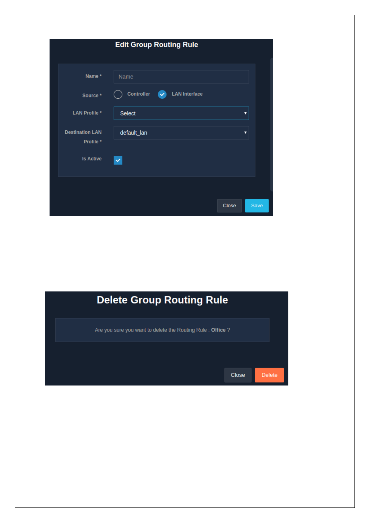
2.10.2.4 Delete Group Routing Rules
To delete a group routing rule, click on the delete icon present in the ‘Operations’ column in the ‘Group
Routing’ sub-section of the ‘Routing’ section, under the ‘Network’ module. A message window appears
displaying a message to confirm the delete action.
Click on the ‘Delete’ button to surely delete the rule.
Fig 2.10.2.3 (b)
Fig 2.10.2.4

3. Wireless
3.3 Wireless Client
This section displays the list of wireless clients connected/disconnected to the UniBox. Wireless clients are
the devices that have obtained an IP address from the UniBox.
• This page displays all wireless clients connected/disconnected with the UniBox. Admin can search,
paginate, and locate particular wireless client for details wireless view.
Each row displays the information about the client including the MAC address, Tx/Rx rate, the RSSI
value for the device, vendor of the device, access point name to which the client is connected and
the SSID connected.
• Admin can view graphical RF history of the client by clicking on the + sign. The history is available for
2, 6, 12 and 24 hours. The graphs show the upload/download speed and signal strength over the
given time interval. This view of the individual wireless client contains a time slot selection for data
visualization to get more insight about wireless clients.
• Connected wireless client are those devices that are associated with the AP .
• Disconnected client means those clients which were connected to AP but are not connected with
the AP from last 15 minutes.
3.3.1 List Wireless Clients
This page displays the list of wireless clients present in the UniBox. The tabular format displays the MAC
Address, Rx Bit Rate, Tx Bit Rate, Time Last Seen, RSSI, Vendor Name, AP Name, SSID and the status of the
client.
It also allows to search for the wireless client by providing a search option based on MAC Address and the AP
Name. Click on the 'Search' button once the desired search criteria have been provided and the list of wireless
clients will be displayed.
The list can be sorted in ascending or descending order using the icon on each column header.
Also the status (connected, disconnected) buttons are provided. Clicking on the ‘Connected’ button would
then display the list of devices which are connected and having the status as ‘UP’. And on click of the
‘Diconnected’ button the devices with status ‘Down’ would be displayed.

The (+) icon corresponding to the mac address displays the graph based on the data captured.
3.3.2 Export Wireless Client
This section allows to download the current list of the connected clients. The report is downloaded with the
name WirelessClient.csv .
The file downloaded follows the following format:
• Mac Address
• RX Bit Rate
• TX Bit Rate
• Last Checking Time
• RSSI
• Vendor Name
Fig 3.3.1
Fig
• AP Name
• SSID
• Status
To export the list of wireless clients, click on the ‘Export’ button.
3.2 Manage AP’s
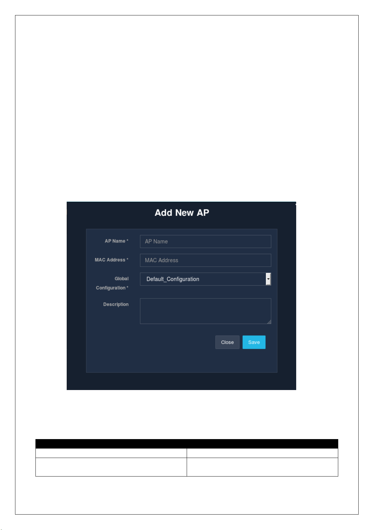
3.2.1 Creation
This page allows administrators to add a new AP for management. If Unibox is used within a wireless network,
then administrators can provision all the access points in Unibox for management. Unibox will check the
status of all APs periodically and will display the status of the AP. For AP Management AP Name and MAC
address of the AP is required.
To add a new access point, click on the ‘+’ icon. A modal form will be displayed that collects the information required
to create a new AP.
The fields marked with asterisk (*) are mandatory.
Click on the ‘Save’ button to add a new AP.
Fields
Description
AP Name
Enter the name of AP.
Mac Address
Enter the MAC address of LAN port of the access
point.
Fig

Global Configuration
Select the configuration to apply to the AP. The AP
will get all the settings applied to the global
configuration.
Description
Enter the description for AP.
Table
3.2.2 List AP’s
This page displays the list of UniMax access points that are provisioned for central management. These APs
can be either manually added to the list or can be provisioned automatically using the auto-discover feature.
Each line displays the AP information along with the current status of the AP. The first column displays the
image (model) of the AP being managed. The name of the AP, private IP and MAC address of the AP are also
displayed. The table also displays the number of clients connected to each AP along with the channel
information for both 2.4 and 5 GHz radios. It also displays the status and the network name of the AP. The
last column, i.e., the ‘Operation’ column, allows an admin to configure or delete the AP from the
management.
This section is also used for push configuration changes to all the managed APs. The admin can filter the AP
list by clicking on one of the buttons; UP, DOWN and UNKNOWN.
Several buttons are available to set the default network configuration, view the auto discovered APs or import
the list of APs from CSV file.
An admin can view more statistics including the time graph of each AP by click on the (+) sign on each line
corresponding to each of the AP.
Fig
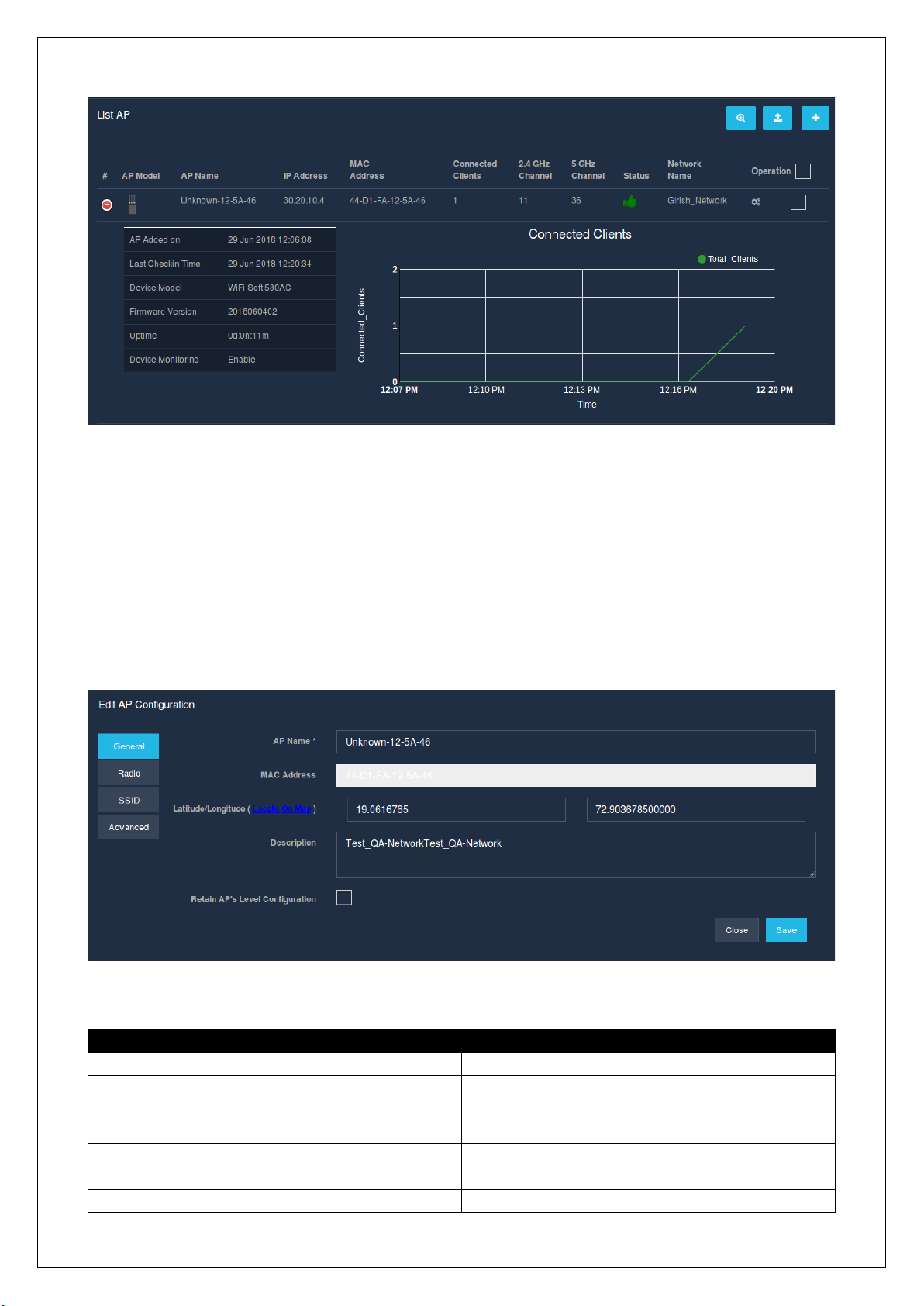
3.2.2 Edit Configuration
This page allows the administrator to edit the Access Point information. To change the access point
information, change the necessary attributes and click the submit button.
The edit AP configuration allows the administrator to edit the different subsections in the AP section. The edit
AP configuration is sectioned into four sub-sections:
• General
Fields
Description
AP Name
Enter/Edit the name of the AP.
MAC Address
Enter the MAC address of the access point. This
field is uneditable. To change the MAC address,
you need to delete and re-add the AP.
Latitude/Longitude
Enter the latitude and longitude of the AP or
select from the google map.
Description
Enter the description for AP.
Fig
Fig

Retain AP’s Local Configuration
Check this box for overriding the default
configuration with the AP's configuration.
Table
• Radio
Fields
Description
Country
Select the country in which your AP is located. The
available channels will change based on the
selected country.
2.4GHz
If the AP has 2.4 GHz radio, select this option.
5GHz
If the AP has 5 GHz radio, select this option.
Channel
Set the channel for operating the given radio. If
the Auto option is selected, the AP will
automatically decide the best channel for
operating.
Tx Power
Set transmit power for the selected frequency
band in DBm.
Max Client
Enter the maximum number of clients that can
connect on the selected band. AP will refuse
additional device once this limit is reached.
Fig

Bandwidth
Select the desired bandwidth (only in case of
5Ghz).
Enable Meshing
To enable WiFi meshing, check the mesh option.
A wireless mesh network (WMN) is a mesh
network created through the connection of
wireless access points installed in each network
user's locale. Generally recommended for dual or
higher band radios. It is important that all APs
must be on the same frequency band for meshing
to work.
Table
• SSID
Fields
Description
SSID1
On ticking-off the checkbox, the data needed to
set the SSID will be captured.
SSID Name
Set the broadcast name of the network.
Hide SSID
If checked, the AP will not advertise the SSID.
Clients will have to enter the SSID manually to
connect to the AP.
Secure with Key
Check this option to enable WPA2 security key.
WPA2-PSK Key
Enter 8 characters or longer key for securing the
network. Only PSK keys are supported.
Broadcasting Bands
Select broadcasting band (2.4, 5 or both) for the
SSID
Enable VLAN
Set ID of VLAN for tagging. All the traffic
connecting to the AP on the given band will get
tagged with the configured VLAN ID.
Table
Fig

• Advanced
The advanced WAN port settings are categorized into three sections:
• Dynamic IP Address
• Static IP Address
• Default/Local
Select whether the APs WAN port will be on static, dynamic or local IP. Generally it is advisable to leave the
AP on a dynamic IP.
In case of dynamic IP address and default or local, the following fields appear:
• Enable Remote Syslog
Fields
Description
Server IP Address
Enter a valid IP address of the server.
Server Port
Enter the port number of the server.
Fig
Fig

Table
• Upgrade Firmware
Fields
Description
Select Version
Select the version.
Take configuration Backup
Check the checkbox if there is a need of saving the
existing configuration backup.
Table
• Reboot AP
• Fast Checkin AP
Fig
Fig

Enable this option during troubleshooting the AP. This will enable faster checking of the AP. Revert back the
change once the debugging is complete.
When we enable the static IP address, it prompts for entering the data in the following fields which are
mandatory:
Fields
Description
Controller Profile
Select the controller profile for static IP.
IP Address
Enter the IP Address.
Netmask
Select the subnet mask.
Gateway
Enter the gateway IP.
Table
Click the ‘Save’ button to save the new AP configuration.
Fig
Fig

3.2.3 Delete AP Configuration
This page deletes an existing Access Point from the management list. All the information about the AP
including the configuration information and monitoring will be lost. Please note that this will not change any
settings on the AP and the AP will continue to operate on the last known configuration.
Click on the ‘delete’ icon, in the ‘Operations’ column, to delete an existing AP configuration. Once clicked, a
message asking for the confirmation of the delete operation pops up.
If you are sure, go ahead and click on the ‘Delete’ button.
3.2.4 Auto Discover AP
This page displays the list of APs that UniBox has auto-discovered and have not been provisioned for
management. All managed UniMax access points use a special protocol to advertise their presence on the
network. UniBox discovers the UniMax APs and checks whether they are already added for management.
If the APs are not managed, UniBox will display them in the list. An admin can review the APs and can
provision them for management.
This page displays all the APs which are under Unibox but not authenticated and provisioned for
Management. The list displays the IP Address, MAC Address, Vendor Name, Last Check-in Time and the
status. To add, click on ‘+’ button.
3.2.5 Import AP
Fig Fig

The file to be imported should be in CSV format. The file should contain the name and
MAC address of the AP. The MAC address of the AP should be separated by dash.
Fields
Description
Global Configuration Profile
Select the global configuration profile.
File to import
Select the valid csv file that is to be imported.
Table
Click on the ‘Import’ button to import the file in the database.
3.2.6 Global Configuration
This page displays all the global configurations.
The table displayed consists several information like Network Name, Created Date and Description.
The page provides an option to edit or delete a global configuration. The global configuration contains the
default settings that will be applied to all APs under management.
The administrator is provided with the operations like add, delete and edit the global configuration.
3.2.6.1 Edit Global Configuration
This page allows the administrator to change an existing global configuration.
The ‘Operations’ column in the list allows an admin to make changes to the global configuration. To edit a
global configuration, click on the edit icon. The changes made will be applied only when the changes are
saved. So click on ’Save’.
Fig
Fig

3.2.6.2 Delete Global Configuration
This page deletes an existing global configuration.
Click on the ‘delete’ icon, in the ‘Operations’ column, to delete an existing global configuration. Once clicked,
a message asking for the confirmation of the delete operation pops up.
If you are sure, go ahead and click on the ‘Delete’ button.
3.2.6.3 Creation
Click on the ‘+’ icon to create or add a new global configuration in the Unibox. A data capture page will be
displayed that collects the information required to create a new global configuration. Click on the ‘Save’
button to save the data into the database.
The fields marked with asterisk (*) are mandatory.
Fig Fig

Click on the ‘Save’ button to save the global configuration. A new global configuration will be added in the
Unibox.
3.3 Heatmap
This section provides the administrator a detailed view of the radiation pattern from each AP (access points)
that are configured with the Unibox. This page is sectioned into 3 parts:
• Connectivity
• Location
• Coverage
The above features will only be enabled, only when you select a floor. In order to add a new floor map, click
on the ‘Configure’ button placed in the right. This button will redirect to the dashboard section. Click on the
‘+’ icon to add a new floor map. A modal will then appear that consists of the following fields:
Fields
Description
Floor Name
Enter a unique name to the floor.
Enter Dimensions
Enter the dimensions in terms of height and
width.
Upload Floor map
Upload the map of the floor where the AP will be
located.
Table
Fig Fig
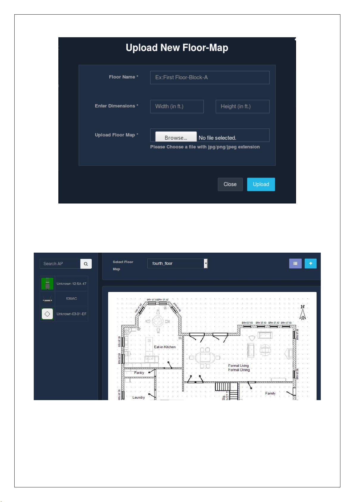
Click on the ‘Upload’ button to add a new floor map in the Unibox. Once the floor map has been uploaded,
select the floor that has just been added. The image would appear in the center like below:
Now click on the AP’s provided in the left corner. You can place these AP’s wherever you wish to on the
selected floor. There is also a search option provided for the AP’s. All you have to do is ‘Drag and Drop’. Select
the type of AP , drag it and drop it to the required position on the floor.
In order to make the process simple and easy, heatmaps have been implemented in a way that :
Fig Fig

• No two floors should have the same image (floor map).
• The same AP should not be placed more than once on a floor.
• If you change the floor through the dropdown and drag and drops the same AP which is already used
for any other floor in the Unibox, will result into popping-up of the confirmation message asking you
whether you are sure of moving the AP from previous to this new floor. If you are sure about moving
the AP, click on the ‘Yes’ button.
After you drag and drop the AP’s, the floor map would appear something like this:
The three major features are explained below :
• Connectivity:
This feature gives the administrator an understanding about the number of devices connected to the AP on
a given floor. Basically, a circle is generated near the AP indicating the devices connected. If you hover the
mouse on the AP, it will show the number of devices connected. Three different colors are used to represent
the number of the devices connected to the AP, namely,
◦ Green – A green circular area indicates the number of devices connected are between 1-2.
◦ Yellow – This color indicates that the number of devices connected is between 2-4.
◦ Red – A red circle is generated if the number of devices connected are 5 or greater than 5.
The below screenshot shows 3 APs out of which only 1 AP has the connectivity area shown. Since to the rest
of the two, there are no devices connected.
Fig

• Location:
This feature is basically to get the location of the user/device. It helps you in tracking the user via the location.
Each of the user’s location is marked accordingly on the floor map.
• Coverage:
Coverage basically indicates the range at which the signal can be reached. Each of the AP’s would have
different coverages dependent on the type of AP. The coverage is represented by 3 different colors:
◦ Green: The circular area filled with green indicates a strong signal. So all the devices close to the
AP will have a strong signal and will be under the area filled with green.
◦ Yellow: Yellow represents average/medium signal strength. The devices falling in this range would
have a slightly weaker signal than that of the ones falling under green.
◦ Red: The red area indicates a weak signal. These are the devices located far from the AP. Due to
which the signal quality reduces.
Fig

The above screenshot represents 3 different AP’s placed on the same floor. Each of these APs have different
coverages. Hence the diameter of the circle differs.
3.3.1 List Floor Map
This section allows the administrator to view the list of floor maps created in the Unibox. The table displayed
lists down the floor name,floor map name,floor map width,floor map height,created date and the date at
which it was last updated. It also allows to perform the searching operation.
3.3.1.1 Edit
This page allows an administrator to change an existing heat map information. The ‘Operations’ column in
the list allows an admin to make changes to a floor map. To edit an existing floor map, click on the edit icon.
A modal is displayed which then captures all the updated information. The changes made will be applied only
when the changes are saved. Click on ’Update’.
Fig
Fig

3.3.1.2 Delete Floor Map
This option allows the admin to delete an existing floor map from the database. Floor maps once deleted,
cannot be restored. To delete the floor map, click on the ‘Delete’ button in the ‘Operations’ section. A
confirmation message pops up to confirm the delete action. Once sure, click on the ‘Delete’ button.
Fig Fig

4. AUTHENTICATION
4.1 Controllers
Controllers is an authentication service in UniBox. UniBox v3.0 supports the execution of multiple
authentication services and captive portals on the same appliance. Each authentication service is controlled
by the controller profile in UniBox. The controller is associated with the LAN profile and will create a hotspot
service on the LAN port. Each controller profile will work independently of the other.
4.1.1 Creation
Select the ‘Controllers’ section from the ‘Authentication’ module present in the sidebar. Click on the ‘+’ icon
to create or add a new controller profile. A modal form will be displayed that collects the information required
to create a new controller profile.
Fig
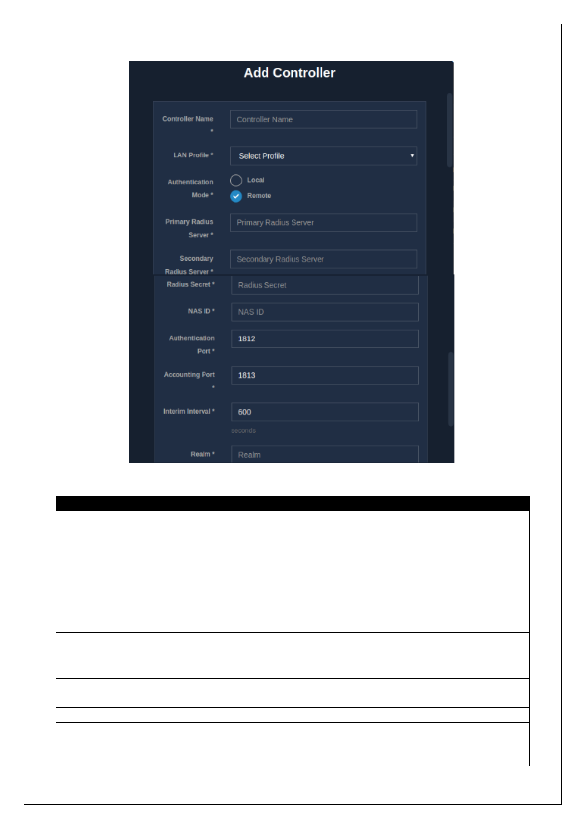
Fields
Decsription
Controller Name
Enter a name for the controller profile.
LAN Profile
Select the LAN profile associated with the profile.
Authentication Mode*
Select one of the authentication modes.
Primary Radius Server #
For remote mode, enter the IP address of the
primary radius server.
Secondary Radius Server #
For remote mode, enter the IP address of the
secondary radius server.
Radius Secret #
For remote mode, enter the radius secret.
NAS ID #
For remote mode, enter the NAS ID.
Authentication Port #
For remote mode, enter the authentication port.
Default: 1812.
Accounting Port #
For remote mode, enter the accounting port.
Default: 1813.
Interim Interval
Enter the interim interval in seconds
Realm
This is an identifier, also called a prefix, that is
appended to the username, delimited by ‘@’.
Username: Sam
Fig

Realm:Sam@1234
There can be NO space or special character while
entering a realm.
Auto-login
If the checkbox is checked, the auth service will
enable MAC login. MAC login enables automatic
authentication of a device using its MAC address.
In case of Auto-login, the captive portal is not
displayed.
Is Active
Tick the checkbox to activate the profile.
Table
NOTE:
* Authentication modes are of two types:
• Local mode: In this mode, the authentication happens locally.
• Remote mode: In this mode, external authentication services are used.
# All these fields are only displayed under the remote authentication mode.
Click on ‘Save’. A new controller profile is created!
4.1.2 List Controller Profiles
The ‘Controllers’ section under the ‘Authentication’ module, displays the list of controller profiles that exist
in the system. Along with the controller name, the list displays the details related to a controller, which
includes the LAN interface associated with the profile, its authentication mode, realm, auto-login function
and whether the controller profile is active or not. Also, it includes the ‘Operations’ column where a controller
profile can be edited or deleted.
4.1.3 Edit Controller Profile
The ‘Operations’ column in the list allows an admin to make changes to a controller profile. To edit an existing
controller profile, click on the edit icon. A modal form is displayed which is similar to the one displayed for
creating a new controller. Refer
Fig

The changes made will be applied only when the changes are saved. So click on ’Save’.
4.1.4 Delete Controller Profile
Click on the ‘delete’ icon, in the ‘Operations’ column, to delete a controller profile. Once clicked, a message
asking for the confirmation of the delete operation pops up. A controller profile can be deleted only if it is
not assigned to any captive portal.
Fig

Once the profile is deleted, the hotspot service on the port will seize to exist. If you are sure, go ahead and
click on the ‘Delete’ button.
4.2 Groups
The ‘Groups’ module allows an admin to define user groups in Unibox. This provides an admin the facility to
assign rules and restrictions to a group of users, instead of assigning it individually to a number of users which
is too tiresome and time-consuming.
4.2.1 Creation
Select the ‘Groups’ section under the ‘Authentication’ module in the sidebar. Click on the ‘+’ icon to create a
new group. A form is displayed which is sectioned into two parts:
• ‘Group Information’ which collects the information required for creating a group.
• ‘Login Restrictions’ which gathers all the restrictions to be applied to the group.
Fig

Fig

Fig

Fields
Description
Group Name
A unique name for the user group.
Description
Brief description about the group.
Controller
Select the controller to which the group belongs
to.
Default Group
Tick the checkbox if the group is to be a default
one. So when the users register, they will be
assigned to this group by default.
Auto MAC Register
Tick the checkbox to enable. If enabled, MAC
address of the user gets registered during the first
authentication request and eventually used for
login on subsequent attempts.
Session Timeout
Enter the session timeout for the users in a group.
After the session timeout, the user’s session will
be closed. Time can be set in seconds, minutes or
hours.
Daily Session Count
Enter the daily session count for the users in a
group per day
Idle Timeout
Enter a time period for users which will close the
user’s session if the connection is kept idle for the
given time period.
Daily Time Quota
Set a time limit which will allow the users to
remain online for that specific time period per
day. Time can be set in seconds, minutes or hours.
Total Time Quota
Set a total time usage quota which will allow the
users to remain online only for that specific time
period.
Daily Bandwidth Quota
Set a data usage limit which will allow the users to
remain online only until the specified data is
consumed by the user per day.
Total Bandwidth Quota
Set a total data usage quota which will allow the
user to remain online until the specified data is
consumed. The value set is the addition of all the
previous data usages.
Download Rate
Enter the bandwidth download rate/ speed for
the users in a group. Select the unit for download
rate, which can be in Kbps, Mbps or Gbps.
Upload Rate
Enter the bandwidth upload rate/ speed for the
users in a group. Select the unit for upload rate,
which can be in Kbps, Mbps or Gbps.
Concurrency Limit
Enter the concurrency limit. Concurrency limit
controls the number of sessions that can be active
at the same time for a particular user. Enter a
concurrency limit.
Max Device Limit
This limit decides the total number of devices a
given user can use to login. This limit counts both
the online and offline devices.
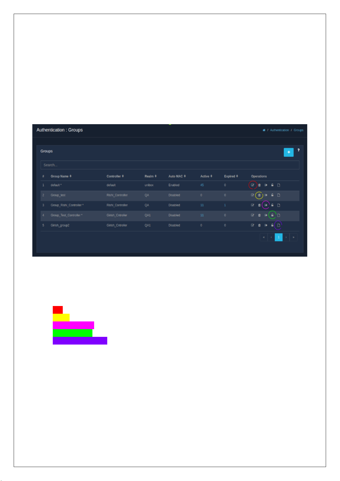
Table
Click ‘Finish’ and you have a new group.
4.2.2 List Groups
When clicked on the ‘Groups’ section under the ‘Authentication’ module in the sidebar, a list of all the existing
groups is displayed. Besides the group name, the list displays the details related to the groups like the
controller profile, realm and the settings of Auto-MAC register. It also displays the number of active and
expired users in each group. The list also maintains an ‘Operations’ column, which gives out several options
to the admin.
The ‘Operations’ column in the listing table facilitates the admin with several actions that can be performed
on the user groups, namely,
• Edit
• Delete
• Clear Auto-login
• Reset Password
• Export Group Activity
4.2.3 Edit Group
The ‘Edit’ option allows an admin to make changes to the information of the existing user groups. Click on the
edit icon in the ‘Operations’ column to edit a user group. A form, similar to the one that was displayed while
creating a new group, will be displayed. Refer
Fig

Fig

Click on ‘Finish’ to save and apply all the changes made.
4.2.4 Delete Group
An admin is given the option to delete a user group if he/she wants to. To delete a user group, click on the
delete icon in the ‘Operations’ column. A message pops up to confirm the delete operation.
Fig
Fig

If sure, click on ‘Delete’ button.
4.2.5 Clear Auto-Login
This option allows the admin to clear auto-login MAC of all the users in a group. Once the MAC addresses are
cleared, the MAC login entries for all the users belonging to the user group will be cleared. The users will be
prompted to login from the captive portal again. All you have to do to clear auto-login is to click on the icon
for clearing the auto-login in the ‘Operations’ column. A message page pops up to confirm the clear autologin action.
If sure, click on ‘Clear Auto Login’ button.
4.2.6 Reset Passwords
An admin is provided with a feature which allows him/her to reset passwords of the users in a group. After
resetting, new passwords will be generated for users. To reset passwords, click on the icon meant for resetting
passwords in the ‘Operations’ column. A confirmation message page is displayed to confirm the reset action.
Click on the ‘ Reset Password’ button if you are sure.
4.2.7 Export Group Activity
Fig Fig

This option allows an admin to export all the users’ activity report for backup purpose. The code report is
exported in PDF or CSV format. Click on the icon assigned to export group activity. A page is displayed where
one has the option to export either a summarized or detailed group activity report. Summarized report will
provide the summary of group activity. The detailed report will provide the details of each activity for the
users in the group.
4.3 User Management
4.3.1 Users
4.3.1.1 Creation
An admin gets to create new users, free or paid, in the database. To create a new user, select the
‘Authentication’ module followed by the ‘User Management’ sub-module and then click on the ‘Users’
section. Finally, click on the ‘+’ icon. A form is displayed, sectioned into three parts:
• Authentication
• General Info
• Restrictions
Fig

Fig

Fig

Fig

Fields
Description
Username
Enter a unique username. Must be of atleast 3
characters and should not contain spaces. UniBox
will automatically append a suffix to the username.
Password
Enter the password for the user. Must be of at least
6 characters.
Confirm Password
Re-enter and confirm the above entered password.
Controller
Select the specific controller to which the user will
belong to.
User Group
Select the user group to which the user will belong
to.
Is Shared Account
Tick the checkbox if the username is to be shared
among multiple users, i.e., the same username will
be used to login from multiple devices at the same
time.
Fullname
Enter the fullname of the user.
Email
Email address of the user. It should be unique.
Address/ City/ State/ Zipcode
Enter the address information of the user.
Country
Select country from the drop-down menu.
Home Phone
Enter the home phone number of the user.
Cell Phone
Enter the cell phone number of the user.
Expiry Date
Enter the expiry date. Use the calendar by clicking
on the calendar icon to enter the date. The user
account will automatically expire on the set date.
Session Timeout
Enter the session timeout for the user which closes
the user’s session after the timeout period. Time
can be set in seconds, minutes or hours.
Daily Session Count
Enter the daily session count for the users which
will not allow the user to login for the remaining
hours once the number of daily sessions exceed.
Idle Timeout
Enter a time period for users which will close the
user’s session if the connection is kept idle for the
given time period.
Daily Time Quota
Set a time limit which will allow the users to remain
online for that specific time period per day. Time
can be set in seconds, minutes or hours.
Daily Bandwidth Quota
Set a data usage limit which will allow the users to
remain online only until the specified data is
consumed by the user per day.
Total Time Quota
Set a total time usage quota which will allow the
users to remain online only for that specific time
period.
Total Bandwidth Quota
Set a total data usage quota which will allow the
user to remain online until the specified data is

consumed. The value set is the addition of all the
previous data usages.
Download Rate
Enter the bandwidth download rate/ speed for the
users in a group. Select the unit for download rate,
which can be in Kbps, Mbps or Gbps.
Upload Rate
Enter the bandwidth upload rate/ speed for the
users in a group. Select the unit for upload rate,
which can be in Kbps, Mbps or Gbps.
Concurrency Limit
Enter the concurrency limit. Concurrency limit
controls the number of sessions that can be active
at the same time for a particular user. Enter a
concurrency limit.
Max Device Limit
This limit decides the total number of devices a
given user can use to login. This limit doesn’t take
concurrency into consideration.
Table
Once the form is filled, click on the ‘Finish’ button. And there! A new user is created.
4.3.1.2 List Users
When the ‘Users’ section is selected under the ‘User Management’ sub-module, a list consisting of all the
local users in the UniBox database is displayed. The list displays the details related to the corresponding to
the username such as the controller assigned, the user group the user belongs to, the user type, i.e., free,
paid or voucher based user, status and also the creation date.
Adjacent to the username, there is a “+“ icon which expands into more information about the user.
Fig

The list also contains an ‘Operations’ column, which provides several options to the admin, like:
• View
• Edit
• Change Password
• Expire
• Export User Activity
In the list page, there is also the feature to search for one or more users based on the various search criteria,
namely,
• Controller: Specific controller profile for search.
• Group name: Specific group name to search.
• Billing Plan: Billing plan for paid users.
• User Attribute: Search on the basis of user attributes.
• Value: Using values or partial names to search.
4.3.1.3 User Details
An admin can view the details and also the session data for a given user. To view the details of a user, admin
can click on either the username or the view icon in the ‘Operations’ column of the listing table. The ‘User
Details’ section contains several details related to a user, categorized into 6 parts:
• Personal Information: Displays the general information about the user, such as email, address, user
type and other extended attributes, if any.

• Live Session Information: Indicates whether the user is online or offline.
• Total Usage: Shows the total usage of data by the user till now.
• Last Five Sessions: Displays details of past five sessions.
Fig Fig Fig
 Loading...