

Wifibot 4G Quick Start Manual

Quick Start Guide
Thank you for choosing WiFiBoT 4G for your robotic application.
• Before using the robot, please read with care this manual
• Keep this manual in a safe place for any future reference
• For updated information about this product visit the official
site of wifibot http://www.wifibot.com
Index
Package contents
Connectors overview
Powering the robot
Power connectors
Battery installation
Camera installation
General structure
Communication interfaces
Embedded sensors
Networking
Configuring the robot
Connecting to the robot
Robot programming
The CDROM
…………………………………………………………………2
…………………………………………………………………2
…………………………………………………………………3
…………………………………………………………………4
…………………………………………………………………5
…………………………………………………………………6
…………………………………………………………………7
…………………………………………………………………8
....………………………………………………………………9
…….………………………………………………………….10
……….……………………………………………………….12
…………….………………………………………………….16
……………….……………………………………………….21
………………….…………………………………………….22
1
Package contents
Make sure to be in possession of all the articles mentioned below. If
any of them should be missing, contact your reseller as soon as
possible.
Robot
IP camera
Two battery packs
Battery charger
Wifibot CD-ROM
Camera CD-ROM and documentation
4x charging cables
1x RJ45 cable for the IP camera
Connectors overview
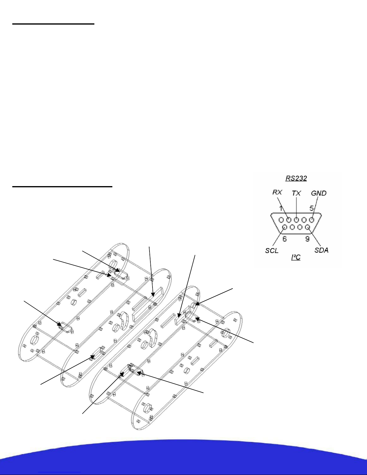
This diagram shows the signal pinout
of the DSUB-9 connectors. The
RS232 signals are found on the
connector located on the left while
the I²C signals can be found on the
connector located on the right of the
robot. (see the other diagram below)
The figure below shows the location of
the different connectors of the robot:
Battery
connector +
Serial
Number
Battery
connector -
Ethernet
switch
Power
ON/OFF
External power and
charging connector
Battery
connector +
I²C
RS232
Battery
connector -
2
Powering the robot
Powering the robot with batteries:
The robot gets its power normally from two battery
packs with four Ni-MH cells each, with a capacity of
9500 mAH and a total nominal voltage of 9,6V.
Located on the upper part of the platform, their
location and clamping have been especially
designed to facilitate their removal and replacement
in an easy and simple way. It is enough to insert the
packs in their connectors, their shape preventing any
error, the only thing left is to close the clamps and
the robot is ready to go. The robot comes with only
two packs, additional packs are available separately.
Powering the robot from an external source:
When developing custom applications it is often
more practical to use an external power source rather
than to have to constantly charge the batteries. Take
out the batteries, then plug the included cable into
the connector located next to the power switch of the
robot and connect the robot to a lab DC power
source at a voltage between 9 and 12 V. Make sure
the power source can deliver several amps,
especially if you plan to test the motors.
3
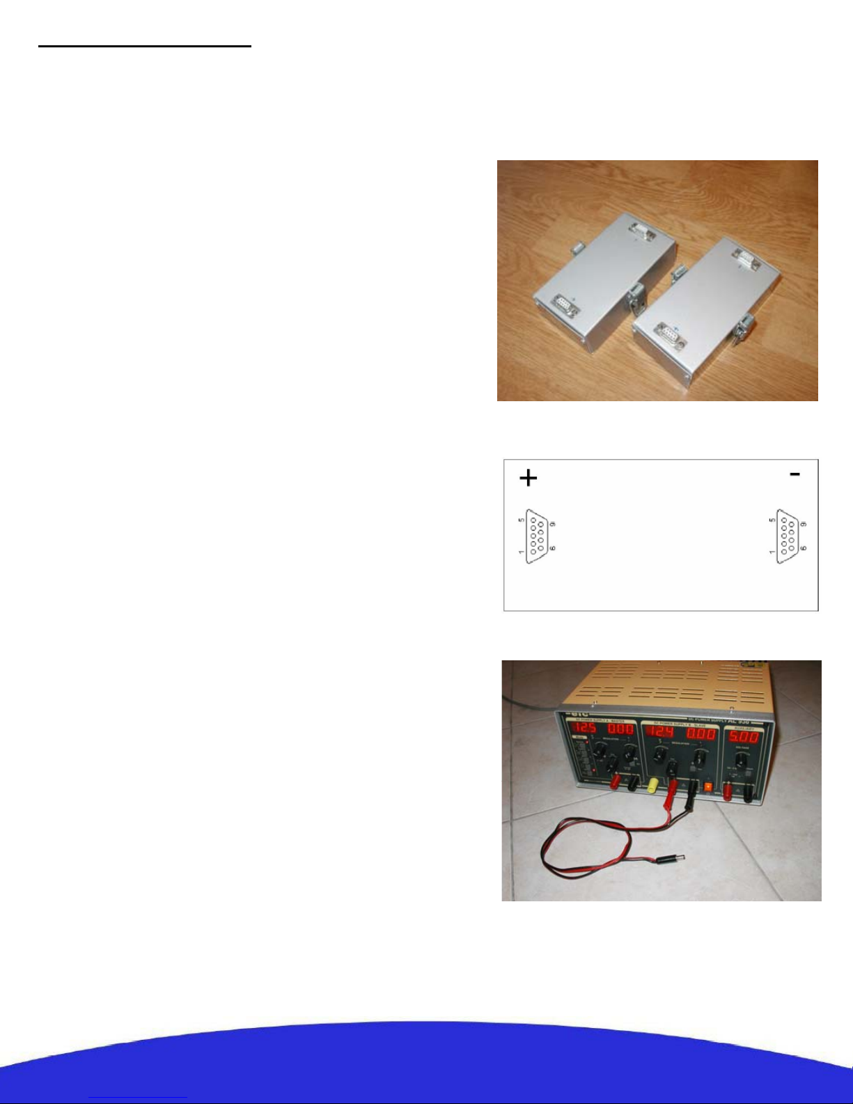
Power connectors
The 5V/9.6V power output:
The robot is equipped with two 5V 2A DC/DC
converters. One of the converters is reserved
exclusively to power the different internal
components of the robot. The second converter is
available to the user through the general power
connector dedicated to external modules such an IP
camera. A direct connection to the batteries is
made available on this connector as well. The 5V
output can’t give more than 2A and a maximum of
10A is recommended for the 9.6V output. An
incorrect use of this connector beyond those values
(short circuit or other) can provoke a malfunction
of the robot or of the DC/DC converter and even
damage those.
Note: The WiFiBoT company will not in any case be considered responsible for any damage
provoked by any incorrect use of this connector. Any reparation necessary for any damage caused
by the incorrect use of this connector will not be covered by the warranty.
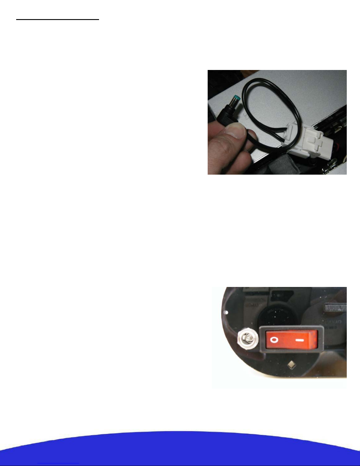
The external power and charging connector:
This connector presents directly the + and – of the robot
and has a double use. On one side it allows to directly
power the robot with an external source without having
to use the batteries. The second use is to charge the
batteries on the robot itself when no additional packs are
available.
Note : When charging the robot make sure the power
switch is OFF so the charger does not find the robot in
march.
4
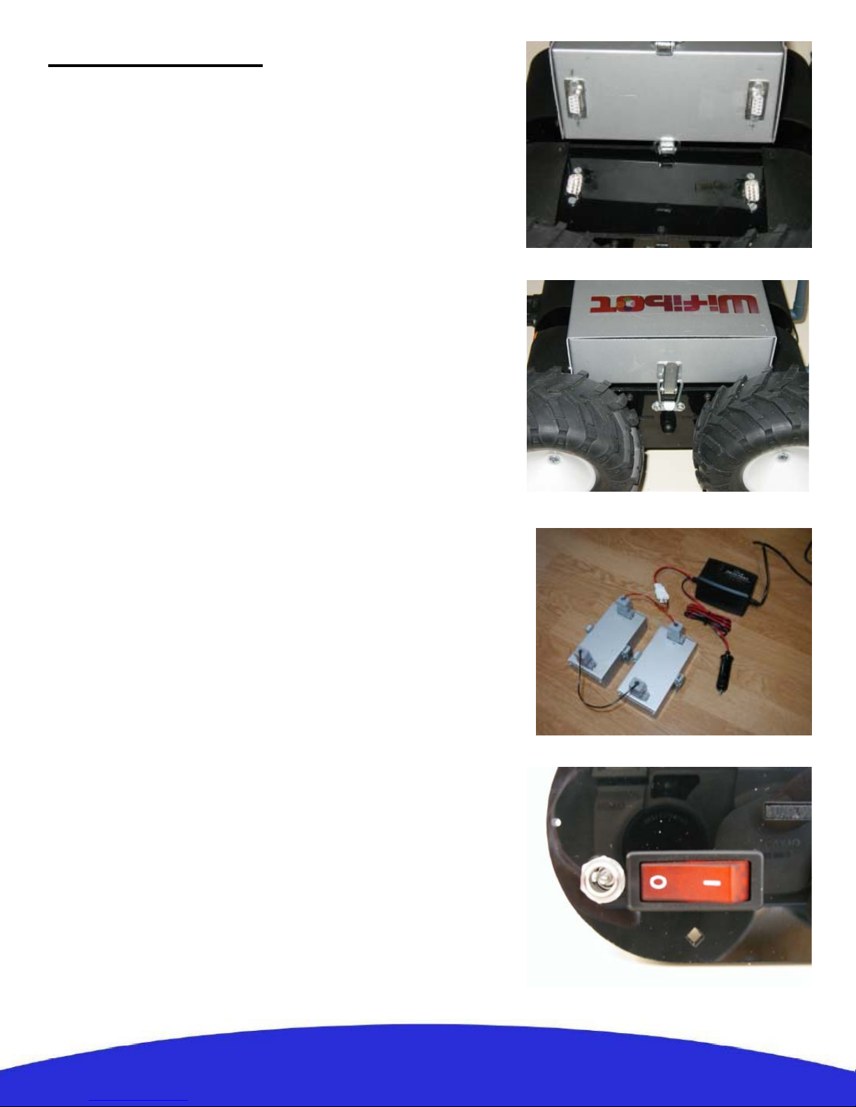
Battery installation
Insertion:
Locate the connectors and their direction on both the
robot and the two battery packs. Insert the batteries
till the end and secure them by closing the lateral
clamps.
Extraction:
Open the clamps and pull the battery packs up.
Charge:
A battery charger is included with the robot and can
be used for charging the batteries in two different
ways:
Externally: This charging mode allows a continuous
use of the robot by doing a rotation of several battery
packs. Insert first each plug in the corresponding
color on the charger side and then connect the three
cables included for this purpose to the batteries as
shown on the photo. (red color with the battery +, see
page 3)
On the robot: This mode is recommended when the
user has only one set of battery packs. First make sure
the robot is OFF, then connect the plugs of the
charging cable on the side of the charger and then on
the charging connector located next to the power
switch of the robot.
5
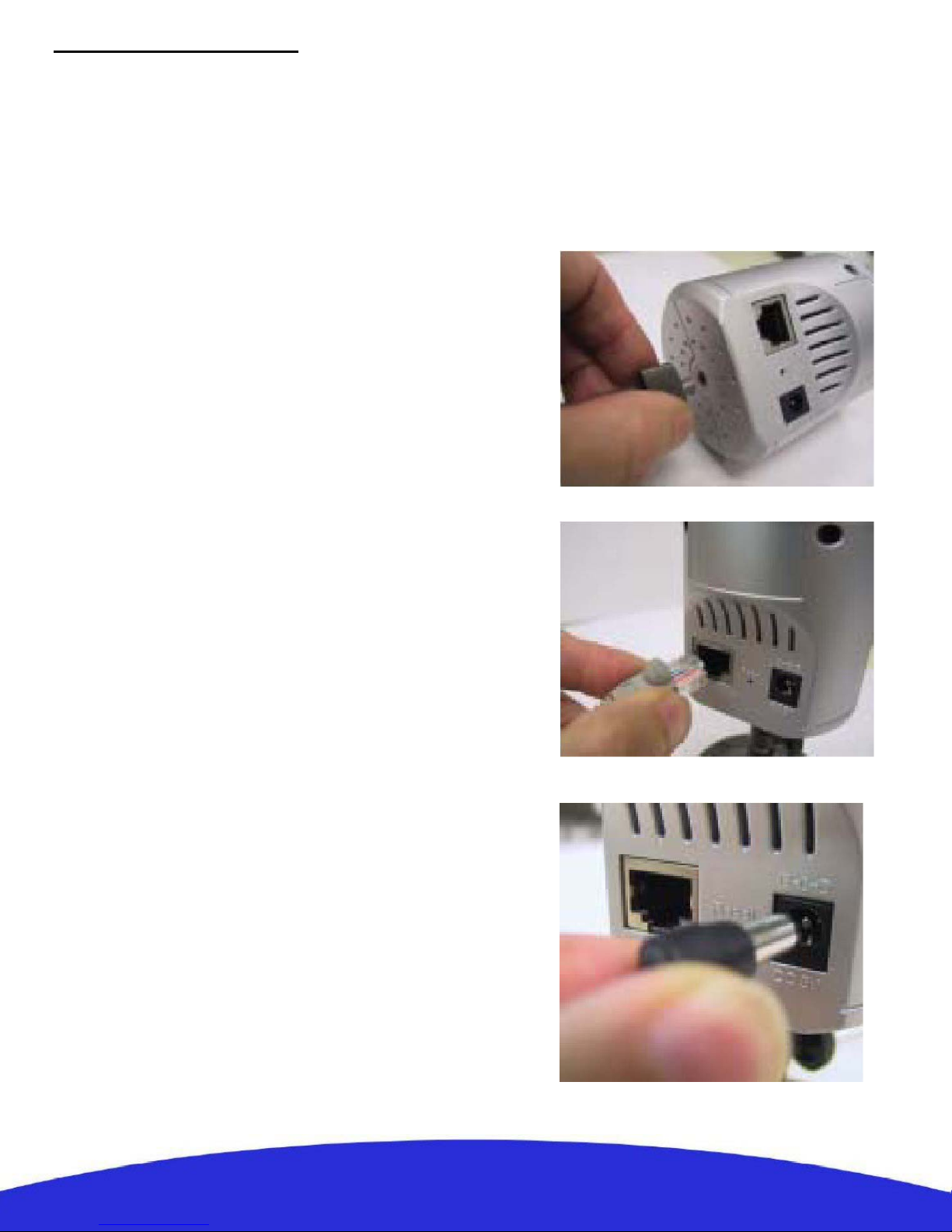
Camera installation
The robot is sold with an IP camera which model can vary depending of the robot version, it
is a complement and is not part of the robot itself. It is an independent peripheral which can
be replaced by any other camera model or network peripheral. For more information about
your particular camera please refer to its manual included in the CD-ROM. Nevertheless its
installation is similar in all models.
Place the camera on the central support:
Screw the camera on its support and if it
applies, adjust manually the desired position
angle.
Connect the Ethernet cable to the camera :
Connect the included Ethernet cable to the
RJ45 port located at the back of the camera
and to one of the ports of the embedded
switch.
Connect the power cable of the camera:
Connect the proper power output (5V/9.6V) of
the robot to the camera power input located at
the back of the camera.
6
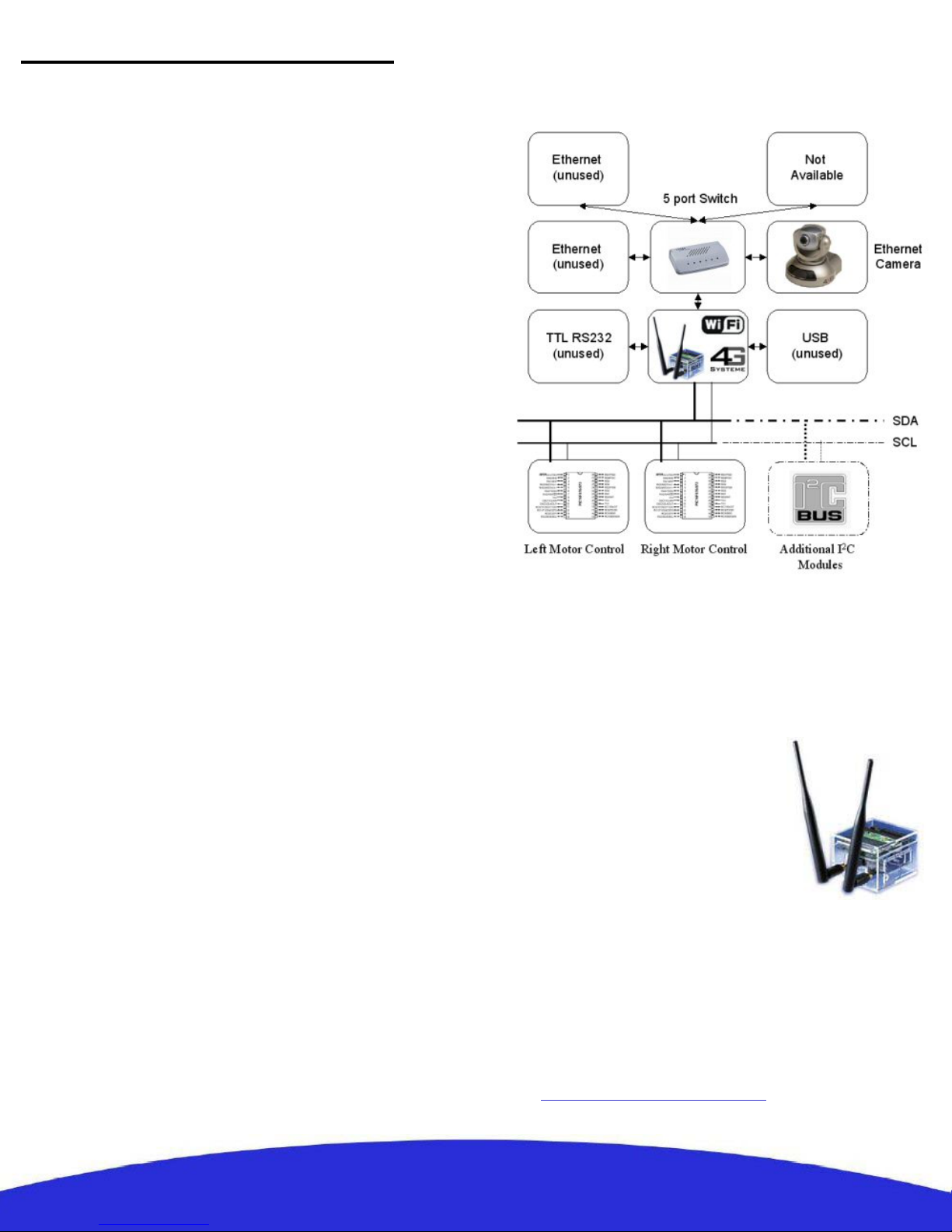
General structure of the robot
System architecture:
The system architecture is very simple, it is build
around a double bus Ethernet-I²C and a CPU that
acts as a bridge between the two. This same CPU
works as an access point and makes the Ethernet bus
accessible from the outside through Wi-Fi. In
general the embedded LAN is used for peripherals
of a certain importance such the IP camera while the
I²C bus is useful for connecting more simple
modules based on micro-controllers. To finish, the
robot features one RS232 port which can be bridged
to upper levels as well. This makes possible to add
to the robot commercial modules as well as “home
made” ones based on simple micro-controllers.
The embedded CPU:
The embedded CPU is a 4G Access Cube from 4Gsystems, some of its interesting features are:
• 400MHz MIPS processor AMD Alchemy Au1500
• 64 MB RAM
• 32 MB Flash
• 100Mbps Ethernet
• Power Over Ethernet Standard IEEE 802.3af
• USB host/USB device (no external plug on robot)
• Scope for installing up to 8 MiniPCI devices via 4
dual adapters.The robot has space for one MiniPCI.
• WLAN card with RP-SMA connection
• Dimensions 7 x 5 x 7 cm
• Power rating 4 W
• No moving parts
The operating software running on the Cube is a
specially adapted Linux distribution “Nylon”. It
provides several features including:
• Linux Kernel 2.4.27
• Mesh Routing (OLSR)
• Web Server
• DNS Server
• DHCP Server/DHCP Client
• Firewall (Shorewall)
•Perl
• Software updates via the Internet
It is totally programmable and all components are
available in source text format. Some
programming examples are included in the CD
and the web page for the distribution can be found
at: http://www.meshcube.org
7
 Loading...