

Operators Manual
Lift Universal
01/16
P R E M I U M
WLU /L Premium
WLU /K Premium WLU /Ks Premium

Operators Manual
Contents
Seite
Safety Rules .......................................................................3
Pre-operation Inspection ..................................................8
Function Tests ...............................................................10
Workplace Inspection ....................................................13
Load Capacity Charts .......................................................16
Transport and Lifting Instructions .....................................17
Specifications ...................................................................18
Internet: www.wienold-lifte.de
E-Mail: info@wienold-lifte.de
Operating Instructions ..................................................14
Installation ....................................................................11
Lift Universal
P R E M I UM
2
Important
Read, understand and obey these safety rules and
operating instructions before operating this machine.
Only trained and authorized personnel shall be
permitted to operate this machine. This manual should
be considered a permanent part of your machine and
should remain with the machine at all times. If you
have any questions, call Wienold in Germany.
Phone: +49 - 5903 - 93 94 0

3
Lift Universal
P R E M I UM
Safety Rules
Operators Manual
Warning
Failure to obey the instructions and
safety rules in this manual may
result in death or serious injury.
Do Not Operate Unless:
You learn and practice the principles of safe
machine operation contained in this operator's
manual.
1 Avoid hazardous situations.
Know and understand the safety rules
before going on to the next section.
2 Always perform a pre-operation
inspection.
3 Always perform the function tests prior to
use.
4 Inspect the workplace.
5 Only use the machine as it was intended.
You read, understand and obey the
manufacturer's instructions and safety rules,
safety and operator's manuals and machine
decals.
You read, understand and obey employer's
safety rules and worksite regulations.
You read, understand and obey all applicable
governmental regulations.
You are properly trained to safely operate the
machine.

Safety Rules
4
Lift Universal
P R E M I UM
Operators Manual
F
all Hazar
ds
Do not
use the
machine as
a personnel
lifting
platform or
step.
Do not
stand
on
the load
handling
attachments.
Do
not climb
on
the mast.
Tip-over
Hazards
Do
not
raise
the
load
unless
the
stabilizers (if
equipped) and
legs have been fully
lowered
and
locked
and the
casters
are
in
full
contact with
the
groun
d.
Do
not
raise the load
u
nless the
leg
retainer
pins
are properly inserted
through the
leg and
the
b
a
s
e.
Do not
remove
the
leg
retainer pins while
the
machine
is loaded and/or
r
ai
sed.
Do
not r
aise
the
load unless
the machine
is on
a
firm,
level surface.
Prior
to
use
,
check
the
work area
for
drop-offs,
holes,
bumps, debris
,
unstable
or slippery
surfaces
or
other
possible hazardous
conditions
.
Do
not r
aise
the
load unless
the
load
handling
attachment is properly
secured
to
the
lift.
Do
not use
blocks
to
level
the
lift.
Do
not
move
the
lift
with a
raised load,
except
for
minor
positioning.
Do
not operate
the lift in
strong
or gusty
winds
.
Increasing
the
load surface area
will
decrease machine
stability in windy conditions
.
Do
not
leave
a load
raised
when
windy
conditions
may
occur unless the
lift
is properly guy-wired.
Do not
cause
a
horizontal force
or
side load
to
the
machine
by
raising
or
lowering a
fixed or
ov
e
r
hangi
ng
lo
a
d
.
5
Lift Universal
P R E M I UM
Safety Rules
Operators Manual
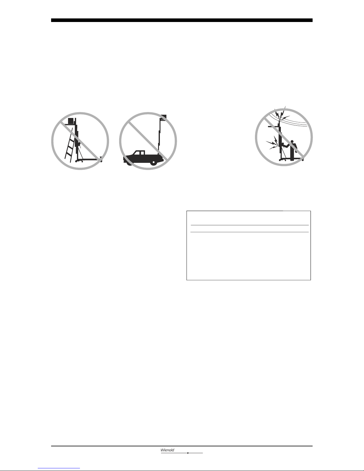
Electrocution Hazards
This lift is not
electrically insulated and
will not provide
protection from contact
with or proximity to
electrical current.
Keep away from the
lift if it contacts
energized power lines. Personnel must not touch or
operate the lift until power lines are shut off.
Maintain safe distances away from electrical power
lines and apparatus in accordance with applicable
governmental regulations and the following chart.
Allow for mast movement and electrical line sway
or sag, and be aware of strong or gusty winds.
Do not use the lift as a ground for welding.
Bodily Injury Hazard
Do not grasp the cable.
Do not place ladders or scaffolding against any part
of the lift.
Do not use the lift on a moving or mobile
surface or vehicle.
Do not exceed the rated load capacity. See Load
Capacity Charts section.
Avoid debris and uneven surfaces while rolling a
lift with the legs folded up.
Do not replace lift parts critical to stability or
structure with items of different weight or
specification.
Lifting Hazards
Use proper lifting techniques to load or tip the
lift.
Use proper lifting techniques when installing or
removing the load handling attachments.
V
oltage
Minimum
Safe
Approach
Distance
Phase to
Phase Feet
Meter
s
0
to 300
V
Avoid
Contact
300V to
50KV
10
3.1
50KV to 200KV
15 4.6
200KV
to 350K
V 2
0 6.
1
350KV to 500
KV
25
7.6
500KV to 750KV
35
10.7
750KV
to
1000KV
4
5 13.7
6
Lift Universal
P R E M I UM
Safety Rules
Operators Manual
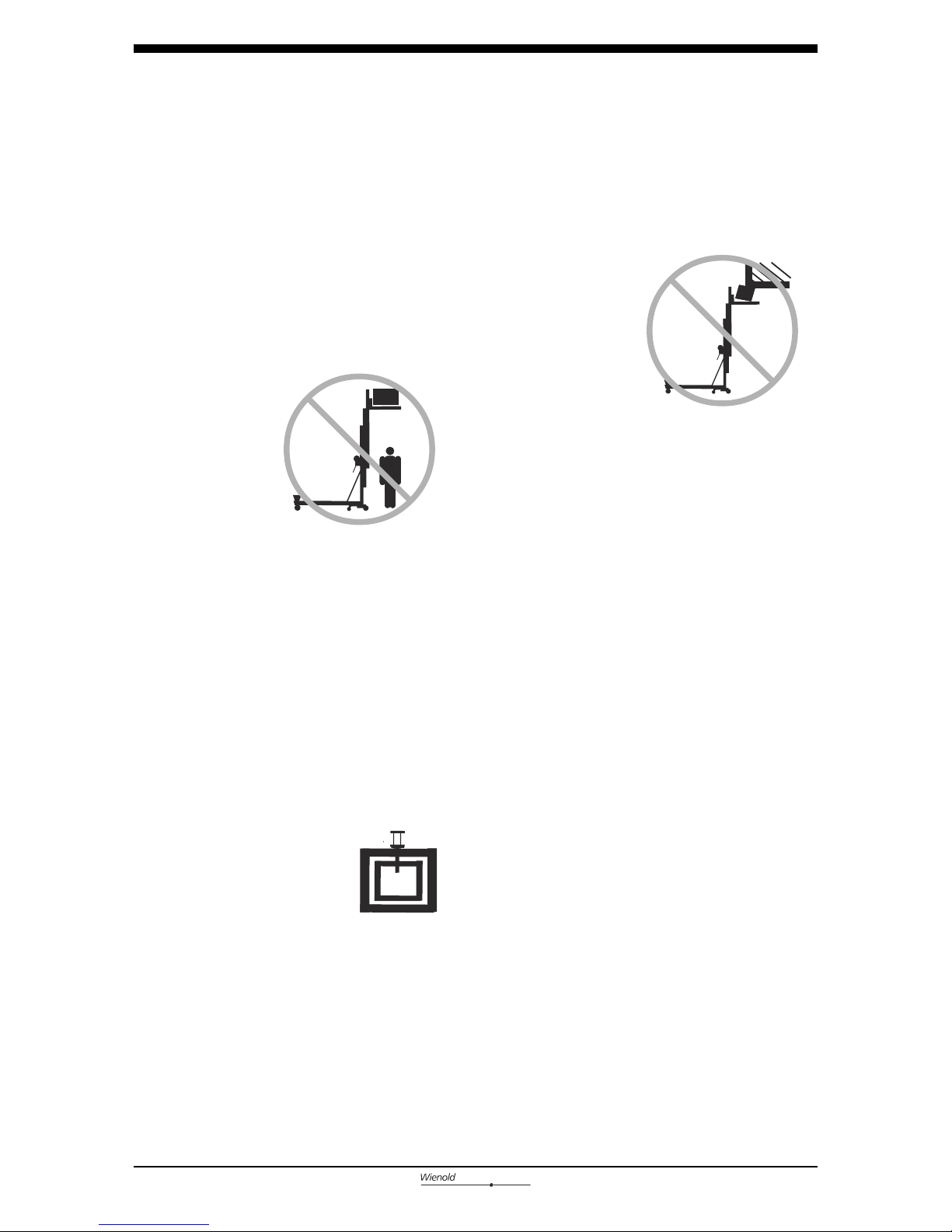
Crushing Hazards
Do not raise if the load is not properly centered on
the load handling attachment.
Do not raise unless the load is properly secured to
the load handling attachment.
Do not stand under or
allow personnel under
the lift when the
load is raised.
Do not stand under the
load. The safety brake
system (if equipped) will
allow the load to drop 1
to 3 feet / 30 to 92 cm
before locking the columns.
Do not lower the load unless the area below is clear
of personnel and obstructions.
Keep hands and fingers away from folding legs and
other potential pinch points.
Maintain a firm grasp on the stabilizer when the
lock plates are released. The stabilizer will drop.
Maintain a firm grasp on the leg when the retaining
pin is removed. The leg will drop.
Maintain a firm grasp on the winch handles until the
brake is locked. The brake is locked when the load
will not cause the winch handles to turn.
Adjustable Flat Forks
Do not raise the load unless the
snap pins are properly inserted
in the forks.
Fork Extensions
Do not raise the load unless the fork extensions are
properly secured to the forks.
Collision Hazards
Check the work area for
overhead obstructions or
other possible hazards.
Do not tilt the lift back
unless the area is clear
of personnel and
obstructions.
Use common sense and planning when transporting
the lift on an incline or slope.
Do not load for transport unless the lift and
vehicle are on a level surface. Use proper lifting
techniques to load the lift.

7
Lift Universal
P R E M I UM
Operators Manual
Safety Rules
Damaged Lift Hazards
Do not use a damaged or
malfunctioning lift.
Do not use a lift with a
worn, frayed, kinked or damaged
cable.
Do not use a lift with less
than 4 wraps of cable on the
winch drum when the carriage is
fully lowered.
Conduct a thorough
pre-operation inspection prior to
each use.
Be sure all decals are in place and legible. See
Decals section.
Be sure that the operator's manual is complete,
legible and in the storage container located on the
lift.
Maintain proper lubrication on the winch.
Do not allow oil or grease on braking surfaces.
Do not use any type of lubrication on the column
surfaces.
Improper Use Hazard
Never leave a lift unattended with a load.
Unauthorized personnel may attempt to
operate the lift without proper instruction,
creating an unsafe condition.
Decal Legend
Wienold product decals use symbols, color coding
and signal words to identify the following:
Safety alert symbol—used to alert
personnel to potential personal
injury hazards. Obey all safety
messages that follow this symbol
to avoid possible injury or death.
Red—used to indicate the
presence of an imminently
hazardous situation which, if not
avoided, will result in death or
serious injury.
Orange—used to indicate the
presence of a potentially
hazardous situation which, if not
avoided, could result in death or
serious injury.
Yellow with safety alert symbol—
used to indicate the presence of a
potentially hazardous situation
which, if not avoided, may cause
minor or moderate injury.
Yellow without safety alert
symbol—used to indicate the
presence of a potentially
hazardous situation which, if not
avoided, may result in property
damage.
Green—used to indicate operation
or maintenance information.

8
Lift Universal
P R E M I UM
Operators Manual
Pre-Operationinspection
Do Not Operate Unless:
You learn and practice the principles of safe
machine operation contained in this operator's
manual.
1 Avoid hazardous situations.
2 Always perform a pre-operation
inspection.
Know and understand the pre-operation
inspection before going on to the next
section.
3 Always perform function tests prior to use.
4 Inspect the workplace.
5 Only use the machine as it was intended.
Fundamentals
The pre-operation inspection is a visual inspection
performed by the operator prior to each work shift.
This inspection is designed to discover if anything
is apparently wrong with a machine before the
operator tests it.
Refer to the list on the next page and check each
of the items.
If damage or any unauthorized variation from
factory delivered condition is discovered, the
lift must be tagged and removed from
service.
Repairs to the lift may only be made by a
qualified service technician, according to the
manufacturer's specifications. After repairs are
completed, the operator must perform a preoperation inspection again before going on to the
function tests.

Pre-operation Inspection
9
Lift Universal
P R E M I UM
Operators Manual
Pre-operation Inspection
Be sure that the operator’s manual is complete,
legible and in the storage container located on
the machine.
Be sure that all decals are legible and in place.
See Decals section.
Check the following components or areas for
damage, improperly installed or missing parts and
unauthorized modifications:
Winch and related components
Base components
Legs
Stabilizers and latch plates (if equipped)
Mast columns
Exterior plastic shim for safety brake
(if equipped)
Carriage hold-down bar
Cable anchor
Cable and pulleys
Wheels and casters
Load handling attachments
Nuts, bolts and other fasteners
Cable (kinks, frays, abrasions)
Check the entire lift for:
Dents or damage
Corrosion or oxidation
Cracks in welds or structural components
Be sure that all structural and other critical
components are present and all associated
fasteners and pins are in place and properly
tightened.
Be sure there is a minimum of 4 wraps of cable
around the winch drum when the carriage is fully
lowered.

Function Tests
10
Lift Universal
P R E M I UM
Operators Manual
Do Not Operate Unless:
You learn and practice the principles of safe
machine operation contained in this operator's
manual.
1 Avoid hazardous situations.
2 Always perform a pre-operation inspection.
3 Always perform function tests prior to
use.
Know and understand the function tests
before going on to the next section.
4 Inspect the workplace.
5 Only use the machine as it was intended.
Fundamentals
The function tests are designed to discover any
malfunctions before the lift is put into service.
The operator must follow the step-by-step
instructions to test all lift functions.
A malfunctioning lift must never be used. If
malfunctions are discovered, the lift must be
tagged and removed from service. Repairs to the
lift may only be made by a qualified service
technician, according to the manufacturer's
specifications.
After repairs are completed, the operator must
perform a pre-operation inspection and function
tests again before putting the lift into service.

11
Lift Universal
P R E M I UM
Installation
Operators Manual
INSTALLATION
IMPOTANT NOTES:
a) Lateral Outrigger
The lateral Outrigger have to be used generally
starting from a vertical lift of 5 meters !
In order to fix the outriggers, pull the snap pins and insert
the Outrigger until its engaged audibly.
b) Insert the Qutrigger-Legs always into the basis until the pins
are locked. Repeat this procedere for each Outrigger-Leg.
c) Do not use the lift with unlocked snap pins.
1. Place the lift at the intended job.
2. Take the Outrigger-Legs from the admission and put it
beside the basis before the installation.
2.1 Lifts Counterbalance Weights
(WLU /L Premium):
Install the LONG Outrigger-Legs at the front and the SHORT T-Outrigger at the backend.
2.2 Lifts WITH Counterbalance Weights
(WLU /K Premium and WLU /Ks Premium):
If the lift is used WITH Counterbalance Weights, the
Outriggr-Legs for the Counterbalance-Weights-Box must be
installed generally at the backend and the short T-Outrigger
always at the frontend. Fix the Counterbalance-Weight-Box
properly and fill it up with the correct number of Weights.
WITHOUT
WLU /K Premium WLU /Ks Premium
WLU /L Premium
Load handling attachments
Adjustable Forks
1. Put the forks into the carriage.
2.
3. Adjust the forks width and check the fitting
for each attaching pin.
Fix the forks with the attaching pin.
Lifts with Standard Attachment
1. Put the forks into the carriage.
2. Fix the forks with the attaching pin.
3. To fix the desired hight of the attachment, select the
appropiate hole at the arm.
6x 9x
Installation
12
Lift Universal
P R E M I UM
Operators Manual
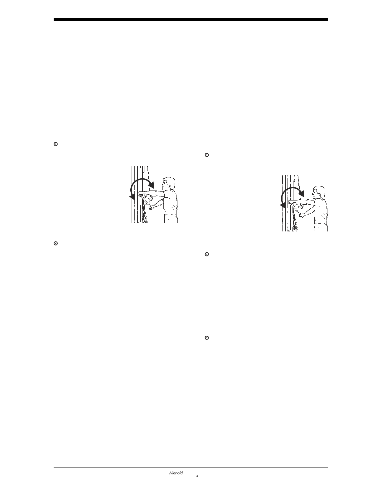
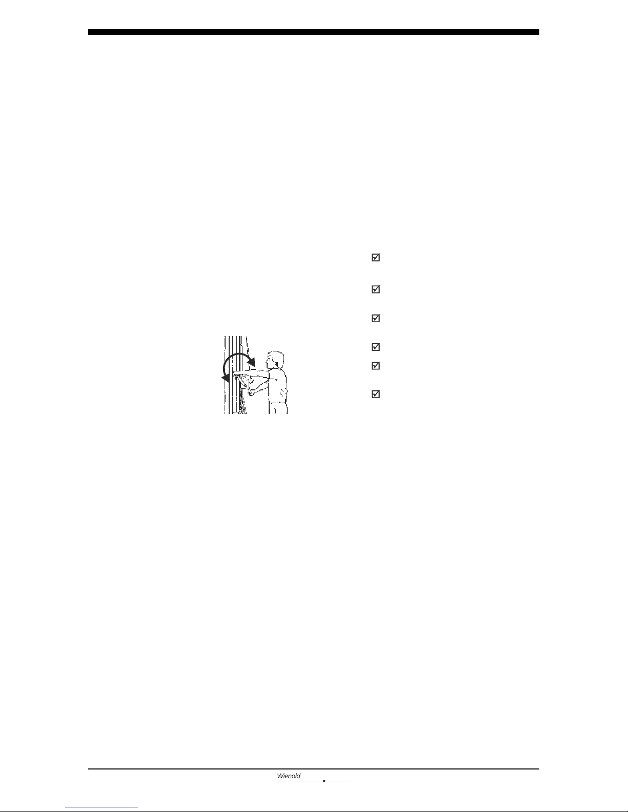
Test Two-Speed Winch Operation
1 Install a load handling attachment.
2 Shift the winch to the slow speed.
3 Raise the carriage by firmly grasping the winch
handles and rotating them towards the mast.
Result: The winch should operate smoothly, free
of hesitation or binding.
4 Lower the carriage by
firmly grasping the
winch handles and
rotating them away
from the mast. After
lowering to the
desired position, turn
the winch handles
toward the mast
(raise the load)
1
/
4
turn to set the brakes.
Result: The winch should operate smoothly, free
of hesitation or binding.
5 Shift the winch to the fast speed and repeat
steps 3 and 4.
Test Mast Sequencing
1 Install a load handling attachment.
2 Raise the carriage to full height by firmly
grasping the winch handles and rotating them
towards the mast.
Result: The carriage should raise to the top of
the front mast section, followed in consecutive
order by each mast section.
3 Fully lower the carriage. After lowering to the
desired position, turn the winch handles toward
the mast (raise the load)
1
/
4
turn to set the brakes.
Test One-Speed Winch Operation
1 Install a load handling attachment.
2 Raise the carriage by firmly grasping the winch
handles and rotating them towards the mast.
Result: The winch should operate smoothly, free
of hesitation or binding.
3 Lower the carriage by
firmly grasping the
winch handles and
rotating them away
from the mast. After
lowering to the
desired position, turn
the winch handles
toward the mast
(raise the load)
1
/
4
turn to set the brakes.
Result: The winch should operate smoothly, free
of hesitation or binding.
down
up
down
up

Workplace Inspection
13
Lift Universal
P R E M I UM
Operators Manual
Fundamentals
The workplace inspection helps the operator
determine if the workplace is suitable for safe
machine operation. It should be performed by the
operator prior to moving the machine to the
workplace.
It is the operator's responsibility to read and
remember the workplace hazards, then watch for
and avoid them while moving, setting up and
operating the lift.
Do Not Operate Unless:
You learn and practice the principles of safe
lift operation contained in this operator's
manual.
1. Avoid hazardous situations.
2 Always perform a pre-operation inspection.
3 Always perform function tests prior to use.
4 Inspect the workplace.
Know and understand the workplace
inspection before going on to the next
section.
5 Only use the lift as it was intended.
Be aware of and avoid the following hazardous
situations:
· drop-offs or holes
· bumps and floor obstructions
· debris
· sloped surfaces
· unstable or slippery surfaces
· overhead obstructions and high voltage
conductors
· hazardous locations
· inadequate surface support to withstand all
load forces imposed by the machine
· wind and weather conditions
· all other possible unsafe conditions

Operating Instructions
14
Lift Universal
P R E M I UM
Operators Manual
Do Not Operate Unless:
You learn and practice the principles of safe
lift operation contained in this operator's
manual.
1 Avoid hazardous situations.
2 Always perform a pre-operation inspection.
3 Always perform function tests prior to use.
4 Inspect the workplace.
5 Only use the lift as it was intended.
Know and understand the operating
Instructions before going on to the next
section.
Fundamentals
The Operating Instructions section provides
instructions for each aspect of machine operation.
It is the operator's responsibility to follow all the
safety rules and instructions in the operator's
manual.
Using the lift for anything other than lifting
material is unsafe.
If more than one operator is expected to use a
lift at different times in the same work shift,
each operator is expected to follow all safety rules
and instructions in the operator's manual. That
means every new operator should perform a preoperation inspection, function tests and a workplace
inspection before using the lift.
15
Lift Universal
P R E M I UM
Operating Instructions
Operators Manual
Moving Lift with a Load
It is best to move the lift on the worksite with
no load. Moving a raised load should be restricted
to positioning for loading and unloading. If it is
necessary to move the lift with a raised load,
understand and obey the following safety rules:
· Make sure the area is level and clear of
obstructions
· Make sure the load is centered on the load
handling attachment
· Make sure the load is secured to the load
handling attachment
· Avoid sudden starts and stops
· Travel with the load in the lowest possible
position
· Keep personnel away from the machine and
load
After Each Use
To prepare the lift for storage, follow the Setup
procedure in reverse order.
Select a safe storage location - firm level surface,
weather protected, clear of obstruction and traffic.
Setup
Select an area that is firm, level and free of
obstructions.
Follow the Setup procedures in the Function Tests
section.
Raising and Lowering Load
1 Center the load on the load handling attachment.
See Load Capacity Charts section.
2 Secure the load to the load handling attachment.
3 Raise the load by firmly
grasping the winch
handles and rotating
them toward the mast.
Do not allow the cable
to wind unevenly onto
the drum.
4 Lower the load by firmly grasping the winch
handles and rotating them away from the mast.
After lowering to the desired position, turn the
winch handles toward the mast (raise the load)
1
/
4
turn to set the brakes
down
up

Load Capacity Charts
16
Lift Universal
P R E M I UM
Operators Manual
Observe and Obey:
Failure to properly position the load may result in
death or serious injury.
Verify that the load you wish to raise does not
exceed the maximum load for your load center.
See the Load Capacity Chart on the next page.
Tip-over hazard. Raising a load
that exceeds the machine capacity
may result in death or serious
injury.
A load center is defined as the balancing point
(center of gravity) of a load and must be
positioned within the load center zone.
Tip-over hazard. Failure to position
the load center within the load
center zone may result in death or
serious injury.
Forks
Load Positioning Instructions
1 Determine the weight of the load and the
location of its load center.
2 Measure to the load center from the side of the
load that will be closest to the carriage.
3 Place the load so that it rests on the forks, as
close to the carriage as possible.
4 Position the load so that the load center is within
the load center zone.
5 Secure the load to the forks.
measure to the load center
Load Center
Zone

14 inch
18 inch
26 inch
22 inch
30 inch 34 inch 38 inch 42 inch
17
Lift Universal
P R E M I UM
Operators Manual
Load Capacity Charts
Boom
Load Positioning Instructions
1 Determine the weight of the load and the
location of its load center.
2 Refer to the chart below to determine if the
machine is capable of lifting the weight at the
location on the boom.
3 Secure the load to the lifting shackle on the
boom.
measure to the load center
Load Capacity Chart
Load Center
in ch 14 18 22 26 30 34 3 8 42
Modell
881 723 593 487 399 326 268 220
lbs
lbs
lbs
Premium 1.7
Premium 2.8
Premium 4.0
lbs
Premium 5.1
881 650 533 436 359 293 240 198
36 cm
46 cm
66 cm
56 cm
76 cm 86 cm 97 cm 107 cm
cm 36 4 6 56 66 76 86 97 10 7
Modell
400 328 269 221 181 148 122 100
kg
kg
kg
Premium 1.7
Premium 2.8
Premium 4.0
kg
Premium 5.1
360 295 242 198 163 133 109 90
400 328 269 221 181 148 122 100
400 328 269 221 181 148 122 100
Load Capacity Chart
Load Center
881 723 593 487 399 326 268 220
881 723 593 487 399 326 268 220
18
Lift Universal
P R E M I UM
Operators Manual
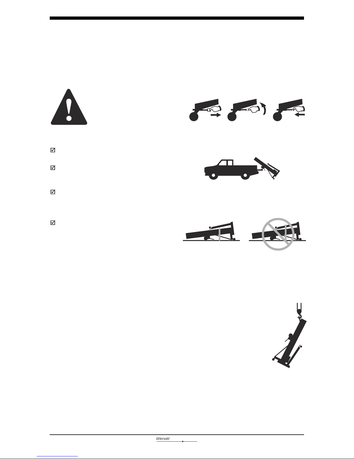
Transport and Lifting Instructions
Observe and Obey:
The transport vehicle must be parked on a level
surface.
The transport vehicle must be secured to
prevent rolling while the lift is being
loaded.
Be sure the vehicle capacity, loading surfaces
and chains or straps are sufficient to withstand
the lift weight. See the serial plate for lift
weight.
The lift must be secured to the transport
vehicle with chains or straps of ample load
capacity.
Loading the Lift
Be sure to remove the load handling attachment
from the lift and place the stabilizers in the
stored position.
1 Fully lower the carriage, to lock for transport.
2 Rotate the carriage hold-down bar over the
carriage.
3 Raise the carriage until it contacts the carriage
hold-down bar.
4 Adjust the loading wheels to the desired
position. Be sure the pin is properly inserted.
Loading Lift with a Crane
Be sure to place the legs and stabilizers in the
stored position.
Be sure to inspect the lift
and remove any loose or
unsecured items.
Use the lifting bracket on the top
of the rear mast column.
Always place the lifting hook
through the lifting bracket so that
it points away from the lift.
Place
the
lift
against
the vehicle
.
Use
proper lifting
techniques to load
the lift
into
the
transport
vehicle.
Be sure to
check that
the
carriage
is locked
in
the
lowered
position.
7 Use
a
minimum
of
1 chain or str
ap to
secure the
lift
to the
truckbed.
Place the chain or
str
ap over the
mast.
Placing
the
chain
or
str
ap
over
the
legs can damage
the legs
.
8
To
unload,
follow the
loading instructions
in
re
v
er
se o
rder
.
5
6
7

Technical Data
19
Lift Universal /L
P R E M I U M
Product specifications are subject to change without notice or obligation.
WLU /L
PREMiUM 1.7
WLU /L
PREMiUM 2.8
WLU /L
PREMiUM 4.0
WLU /L
PREMiUM 5.1
Working height - standard fork up:
- standard fork down:
- adjustable fork up:
- adjustable fork down:
- boom:
Storage measures - height:
- length:
- width:
Working position - height:
- length:
- width:
- clearance:
Loading height min.:
Pay load:
Dead weight (without outrigger, weights, etc.)
Weight outrigger:
1,70 m
1,31 m
1,70 m
1,31 m
1,60 m
1,68 m
0,63 m
0,50 m
1,74 m
1,77 m
0,75 m
0,05 m
0,37 m
881 lbs (400 kg)
214 lbs (97 kg)
75 lbs (34 kg)
5,15 m
4,76 m
5,15 m
4,76 m
5,06 m
1,68 m
0,63 m
0,50 m
1,74 m
1,77 m
0,75 m
0,05 m
0,37 m
793 lbs (360 kg)
320 lbs (145 kg)
75 lbs (34 kg)
2,85 m
2,46 m
2,85 m
2,46 m
2,75 m
1,68 m
0,63 m
0,50 m
1,74 m
1,77 m
0,75 m
0,05 m
0,37 m
881 lbs (400 kg)
250 lbs (113 kg)
75 lbs (34 kg)
4,00 m
3,60 m
4,00 m
3,60 m
3,90 m
1,68 m
0,63 m
0,50 m
1,74 m
1,77 m
0,75 m
0,05 m
0,37 m
881 lbs (400 kg)
285 lbs (129 kg)
75 lbs (34 kg)
1,70 m
1,31 m
1,70 m
1,31 m
1,60 m
1,68 m
0,63 m
0,50 m
1,74 m
1,77 m
0,75 m
0,05 m
0,37 m
881 lbs (400 kg)
214 lbs (97 kg)
75 lbs (34 kg)
212 lbs (96 kg)
WLU /K
PREMiUM 1.7
5,15 m
4,76 m
5,15 m
4,76 m
5,06 m
1,68 m
0,63 m
0,50 m
1,74 m
1,77 m
0,75 m
0,05 m
0,37 m
793 lbs (360 kg)
320 lbs (145 kg)
75 lbs (34 kg)
212 lbs (96 kg)
2,85 m
2,46 m
2,85 m
2,46 m
2,75 m
1,68 m
0,63 m
0,50 m
1,74 m
1,77 m
0,75 m
0,05 m
0,37 m
881 lbs (400 kg)
250 lbs (113 kg)
75 lbs (34 kg)
212 lbs (96 kg)
4,00 m
3,60 m
4,00 m
3,60 m
3,90 m
1,68 m
0,63 m
0,50 m
1,74 m
1,77 m
0,75 m
0,05 m
0,37 m
881 lbs (400 kg)
285 lbs (129 kg)
75 lbs (34 kg)
212 lbs (96 kg)
WLU /K
PREMiUM 2.8
WLU /K
PREMiUM 4.0
WLU /K
PREMiUM 5.1
Lift Universal /K
P R E M I U M
Lift Universal
P R E M I UM
Operators Manual
Working height - standard fork up:
- standard fork down:
- adjustable fork up:
- adjustable fork down:
- boom:
Storage measures - height:
- length:
- width:
Working position - height:
- length:
- width:
- clearance:
Loading height min.:
Pay load:
Dead weight (without outrigger, weights, etc.)
Weight outrigger:
Counterbalance weights (6x16kg)

Product specifications are subject to change without notice or obligation.
1,70 m
1,31 m
1,70 m
1,31 m
1,60 m
1,68 m
0,63 m
0,50 m
1,74 m
1,06 m
0,75 m
0,05 m
0,37 m
881 lbs (400 kg)
214 lbs (97 kg)
58 lbs (26 kg)
318 lbs (144 kg)
WLU /Ks
PREMiUM 1.7
5,15 m
4,76 m
5,15 m
4,76 m
5,06 m
1,68 m
0,63 m
0,50 m
1,74 m
1,06 m
0,75 m
0,05 m
0,37 m
881 lbs (360 kg)
320 lbs (145 kg)
58 lbs (26 kg)
318 lbs (144 kg)
2,85 m
2,46 m
2,85 m
2,46 m
2,75 m
1,68 m
0,63 m
0,50 m
1,74 m
1,06 m
0,75 m
0,05 m
0,37 m
881 lbs (400 kg)
250 lbs (113 kg)
58 lbs (26 kg)
318 lbs (144 kg)
4,00 m
3,60 m
4,00 m
3,60 m
3,90 m
1,68 m
0,63 m
0,50 m
1,74 m
1,06 m
0,75 m
0,05 m
0,37 m
881 lbs (400 kg)
285 lbs (129 kg)
58 lbs (26 kg)
318 lbs (144 kg)
WLU /Ks
PREMiUM 2.8
WLU /Ks
PREMiUM 4.0
WLU /Ks
PREMiUM 5.1
Lift Universal /Ks
P R E M I U M
20
Lift Universal
P R E M I UM
Operators Manual
Technical Data
Working height - standard fork up:
- standard fork down:
- adjustable fork up:
- adjustable fork down:
- boom:
Storage measures - height:
- length:
- width:
Working position - height:
- length:
- width:
- clearance:
Loading height min.:
Pay load:
Dead weight (without outrigger, weights, etc.)
Weight outrigger:
Counterbalance weights (9x16kg)


Norbert Wienold GmbH
Industriegebiet Waldstr. 35a
D- 48488 Emsbüren
Germany
Phone +49 - 59 03 - 93 94 0
Fax +49 - 59 03 - 93 94 50
www.wienold-lifte.de
e-mail: info@wienold-lifte.de
Niederlassungen:
Leverkusen - Walsrode
Brandenburg - Emsbüren
München - Frankfurt
 Loading...