

Page 1
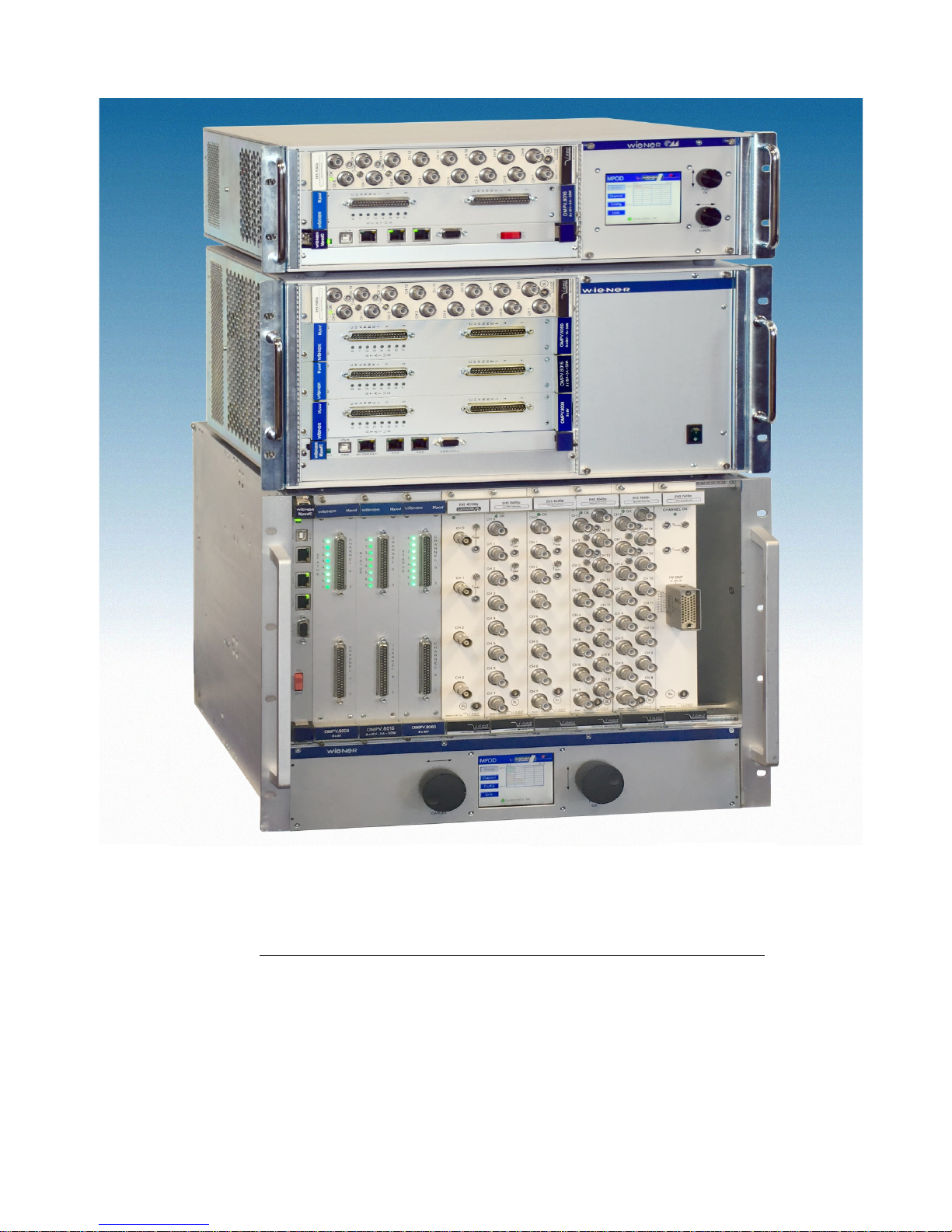
30. May 2018 Version 3.0
MPOD HV & LV
Power Supply System
Technical Manual
Page 2

General Remarks
The only purpose of this manual is a description of the product. It must not be interpreted as a
declaration of conformity for this product including the product and software.
W-Ie-Ne-R revises this product and manual without notice. Differences of the description in
manual and product are possible.
W-Ie-Ne-R excludes completely any liability for loss of profits, loss of business, loss of use or
data, interrupt of business, or for indirect, special incidental, or consequential damages of any
kind, even if W-Ie-Ne-R has been advises of the possibility of such damages arising from any
defect or error in this manual or product.
Any use of the product which may influence health of human beings requires the express written
permission of W-Ie-Ne-R.
Products mentioned in this manual are mentioned for identification purposes only. Product names
appearing in this manual may or may not be registered trademarks or copyrights of their
respective companies.
No part of this product, including the product and the software may be reproduced, transmitted,
transcribed, stored in a retrieval system, or translated into any language in any form by any means
with the express written permission of W-Ie-Ne-R.
Control Cabinet
In the context of this user manual, the control cabinet must fulfill the requirements on fireprotective enclosures according to EN 60950 / IEC 60950 / UL 60950.
All devices are intended for operation in control cabinets or in closed areas. The LAN connection
and all wire connections between the different system parts must be done via shielded cable with
conductive connector shells, which are fixed with screws.
Furthermore, an additional fire-protective enclosure is required which must not affect proper air
circulation.
30. May 2018 1
Page 3
Mains Voltage and Connection
The Power supplies are equipped with a “World”- mains input (rated voltage range: 100-240
VAC, frequency: 50-60 Hz, rated current: 16 A). Before connecting to the mains please
double-check correspondence.
Mains input connection at the power supply side is done with a 3-pin HIRSCHMANN
connector or power terminals. There is no main fuse inside. A circuit breaker for overcurrent
protection 16A, type B or C (EN / IEC 60898, VDE 0641), has to be installed externally.
Before disconnection the HIRSCHMANN connector, the power supply should be switched
into standby state. (Use the ON/OFF-Switch of the front pannel of the MPOD system)
Hirschmann. Signal Description Color of the Wire
Pin 1 L Phase black or brown
Pin 2 N Return, Neutral blue
Pin 3 not connected
Earth PE Protective Earth green/yellow
Connection to Earth
Safety
After connecting the Power box to the mains, the mains input module is powered permanently.
Filter and storage capacitors of the power factor correction module are charged with about
400VDC. Any DC-On-Signal as well as a power switch at control board (if any installed) operates
as a low voltage DC on/off switch only and not as a mains breaker. Therefore it becomes
dangerous if the box cover is open. In this case a lot of components on high voltage potential
get touchable!
Before starting any kind of work inside the power box remove the unit from mains and wait
a couple of minutes with your activities! Discharge the primary DC Filter-capacitors by use
of a well isolated 22 ohm 10W resistor.
We recommend in case of any malfunction to send the power box to Wiener or to one of our
representative for service
The backplane is connected to 385 V DC voltage. So never touch the backplane or its
connectors!
30. May 2018 2
Page 4

EU Declaration of Conformity (DoC)
We
Company name: W-IE-NE-R Power Electronics GmbH
Postal address: Linde 18
Postcode, City: 51399 Burscheid
Contry: Germany
Telephone number: +49-2174-678-0
E-Mail address: [email protected]
declare that the DoC is issued under our sole responsibility and belongs to the following products:
Apparatus model/Product: Mpod Power Supply System
Type: 0P09.xxxx,0316.xxxx, 0BP0.9xxx, 0R00.00xx
Apparatus model/Product: Mpod mini/micro Power Supply System
Type: 0377.xxxx
The object of the declaration described above is in conformity with the relevant Union harmonisation
legislation:
Low Voltage Directive (LVD) 2014/35/EU
Electromagnetic Compatibility (EMC) Directive 2014/30/EU
The following harmonised standards and technical specifications have been applied:
Title, Date of standard/specification:
Safety
EN 62368-1:2014 Audio/video, information and communication
technology equipment
— Part 1: Safety requirements
EN 60950-1:2006 Information technology equipment – Safety
EN 61010-1:2010 Safety requirements for electrical equipment for
measurement,control, and laboratory use
EN 61000-6-3:2007 Störaussendung [emmission] resitential, commercial and
light-industry evnironments]
EN61326-1:2013 Cl. A/B (emmission) Electrical equipment for measurement, control and
laboratory use - EMC
EN 55022:2010 Cl. A/B Störaussendung [RF Emmission] Information technology equipment
EN 55022:2010 Cl. B Störspannung [conducted noise]
EN 55022:2010 Cl. A/B Störfeldstärke [radiated noise]
EN 55015-1:2006 Knackstörungen [clicks
EN 61000-3-11:2000 Spannungsschwankungen [flicker]
EN 61000-3-12:2011 Oberschwingungen [harmonics]
EN 61000-6-2:2005 Störfestigkeit [immunity] industrial environments]
EN61326-1:2013 Cl. A (immunity) Electrical equipment for measurement, control and
laboratory use - EMC
EN 55024:2010 Störfestigkeit [immunity] Information technology equipment
EN 61 000-4-2:2010 ESD
EN 61 000-4-3:2011 HF-Felder [radiated HF fields]
EN 61 000-4-4:2013 Burst
EN 61 000-4-5:2015 Surge
EN 61 000-4-6:2014 HF-Einströmung [injected HF currents]
EN 61 000-4-8:2010 Mangn. Feld [magn. fields]
EN 61 000-4-11:2005 Spannungs-Variationen [voltage variations]
Signed for and on behalf of:
Burscheid 2018-02-14
Andreas Köster, General Manager
Place of issue Date of issue Name, function, signature
30. May 2018 3
Page 5

Contents
1 General Information.........................................................................................................6
1.1 MPOD Features........................................................................................................6
1.2 MPOD Crate - standard types...................................................................................7
1.3 MPOD Mini crate.......................................................................................................8
1.4 MPOD Micro crate.....................................................................................................8
2 LV Modules......................................................................................................................9
2.1 MPOD Low Voltage Module Versions....................................................................10
2.2 Combined Power & Sense Connector Pin Assignment (standard female type)... .11
2.3 Power & Combined Power & Sense Connector 4 channel modules (DSUB4W17
type)...............................................................................................................................12
2.4 Sense & Control Connector Pin Assignment (modules with 4 channel + DSUB37-
8)....................................................................................................................................13
2.5 Combined Power & Sense Connector Pin Assignmen (standard female 4 channel )
........................................................................................................................................14
2.6 Combined Power & Sense Connector Pin Assignmen (standard female 2 channel )
........................................................................................................................................15
2.7 Power Connector Pin Assignment (modules with mixed DSUB37 + DSUB37-8). .16
2.8 SAFETY LOOP and optional INTERLOCK functionality of MPV modules.............17
3 HV Modules...................................................................................................................18
4 MPOD Controller...........................................................................................................20
5 CC24 Controller (optional Controller istead of MpodC)................................................22
6 Local Control.................................................................................................................23
6.1 Introduction.............................................................................................................23
6.2 Usage of the rotary controls....................................................................................23
6.3 MPOD Display Main menu......................................................................................25
6.4 MPOD Display CHANNEL menu............................................................................26
7 Remote Control / Software............................................................................................29
7.1 Software Setup for Microsoft Windows...................................................................29
7.2 Web Browser...........................................................................................................32
7.3 NetSNMP................................................................................................................33
7.4 ISEG High voltage module special commands......................................................39
7.5 ISEG Load unit module commands........................................................................43
7.6 ISEG Module commands........................................................................................44
7.7 Change of community names / setting of passwords.............................................44
7.8 MIB Browser............................................................................................................45
7.9 A BASH Simple Script for SNMP............................................................................46
7.10 MPOD SNMP Parameter List (most common).....................................................48
7.11 LabView Control Program (NETSNMP)................................................................49
7.12 ISEG SNMP Control Program (NETSNMP).........................................................49
7.13 C++ programming (NetSNMP)..............................................................................50
8 MPOD Crate..................................................................................................................52
9 Primary Power Supply...................................................................................................52
9.1 Power Box Data Sheet............................................................................................52
10 MPOD Low Voltage module MPV 8xx data sheet......................................................53
11 SNMP examples for MPOD and high voltage EHS/EDS module...............................55
12 WIENER SNMP Parameter structure..........................................................................57
13 MPOD Firmware Update.............................................................................................66
14 MPOD Display Firmware Update................................................................................71
15 ISEG HV Module Firmware Update vias Ethernet / SNMP........................................73
16 Instruction to change the Bitrate.................................................................................80
30. May 2018 4
Page 6

Figures
Tables
30. May 2018 5
Page 7
1 General Information
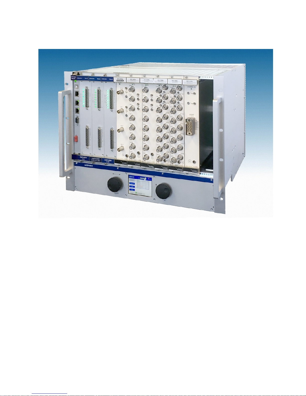
MPOD crate with mixed low and high voltage modules
1.1 MPOD Features
MPOD is a mainframe for multi-channel high voltage (HV) and low voltage (LV) power supply modules.
A unique flexibility is given by outfitting the MPOD crate with either the LV or HV backplane only or
with both to allow combined use of LV and HV modules. The full size MPOD crate has 10 slots for power
modules which provides a high number of output channels. Its modular design makes the customer able to
easily replace the fan tray, the controller, the primary power supply or the optional air filter.
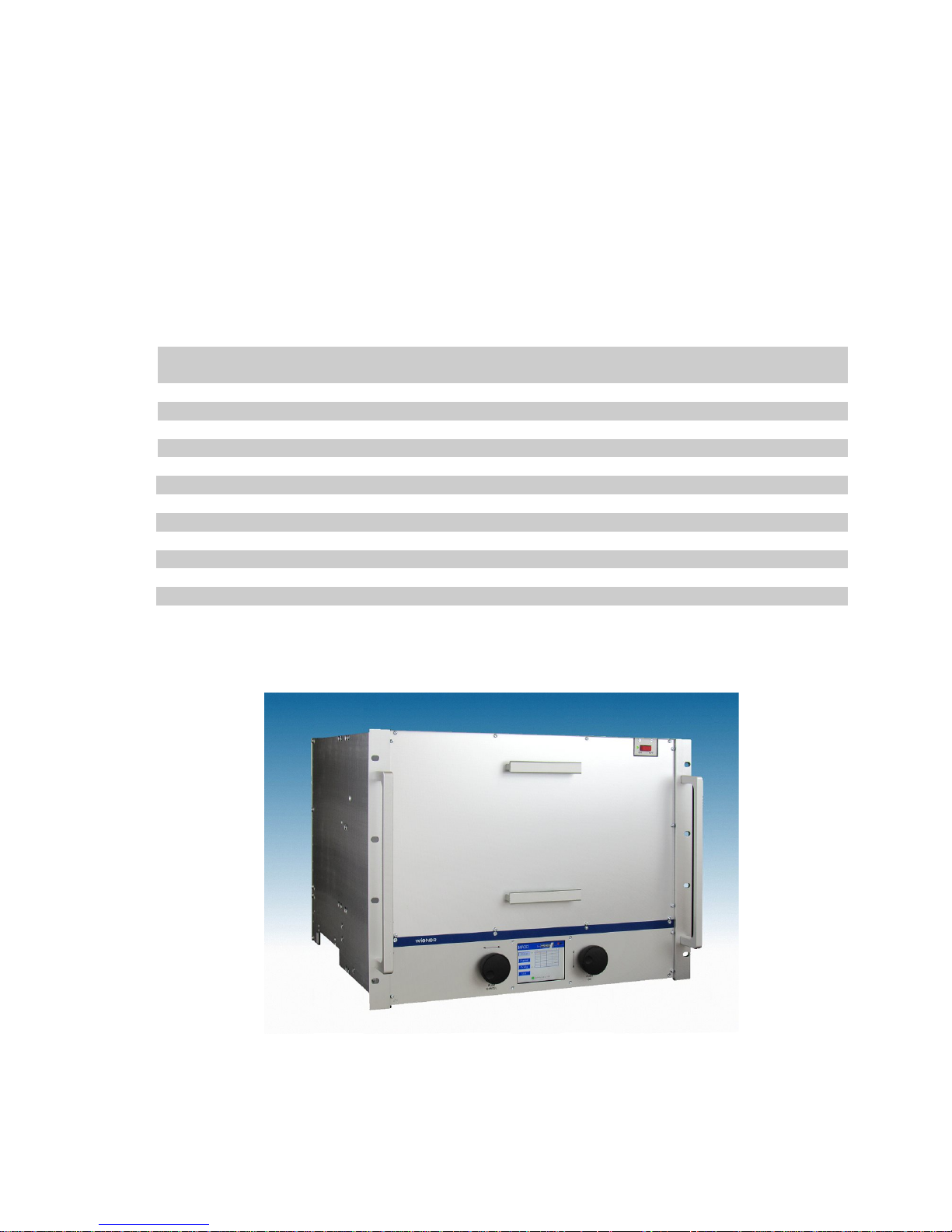
Since 2017 with new compact design and integrated air filter.
● 10 module slots for up to 80 LV channels / up to 480 HV channels
● 8U high for bottom cooling air intake, optional dust filter
● Modules and controller outputs can be placed either at front or rear side (picture above shows front
side)
● LV: 8 channels (0- 8/16/30/60V/120V, 50W / channel, floating
● HV: 480 / 320/240 / 160 / 80 or 40 channels (0- 2.5/4/6kV/8kV/10kV), channel- or module wise
floating or common ground
● Low noise and ripple
● Individually controlled output channels (voltage and current), programmable warning and trip
levels
● MPOD Controller with Ethernet (TCP/IP) / CANbus / USB Combi-interface, Interlock
30. May 2018 6
Page 8
● Ethernet port with integrated Web server, programmable with SNMP protocol via TCP/IP, OPC
● CE conform EN 50 081/82 part 1 (EN 50 022 B)
● safety in accordance with EN 60 950
● Sinusoidal mains current EN 61000-3-2
1.2 MPOD Crate - standard types
The following crate types are standardized configurations with 8U high chassis. Optionally a filter frame is
available with bottom or front air inlet
Other configurations and mixed system with part of the crate outfitted with PCI or VME backplanes are
available on request.
Type Slots Remote control
interface
Local control /
display
Backplane HV
power
Output
Position
MPOD EC 10 Ethernet, CAN, USB - HV/LV 600W front
MPOD EC-R 10 Ethernet, CAN, USB - HV/LV 600W rear
MPOD LX 10 Ethernet, CAN, USB Yes, LCD HV/LV 600W front
MPOD LX-R 10 Ethernet, CAN, USB Yes, LCD HV/LV 600W rear
MPOD EC-LV 10 Ethernet, CAN, USB - LV - front
MPOD EC-LV-R 10 Ethernet, CAN, USB - LV - rear
MPOD EC-HV 10 Ethernet, CAN, USB - HV 600W front
MPOD EC-HV-R 10 Ethernet, CAN, USB - HV 600W rear
MPOD 2H 10 Ethernet, CAN, USB - HV 1200W front
MPOD 2H-R 10 Ethernet, CAN, USB - HV 1200W rear
MPOD 2H-LX 10 Ethernet, CAN, USB Yes, LCD HV 1200W front
MPOD 2H-LX-R 10 Ethernet, CAN, USB Yes, LCD HV 1200W rear
(CAN-bus for HV modules only, disabling Ethernet communication may be necessary for ISEG CAN-HV
control software)
MPOD LX crate with reversed Card cage
Optionally, MPOD can be outfitted with an internal removable air filter
30. May 2018 7
Page 9
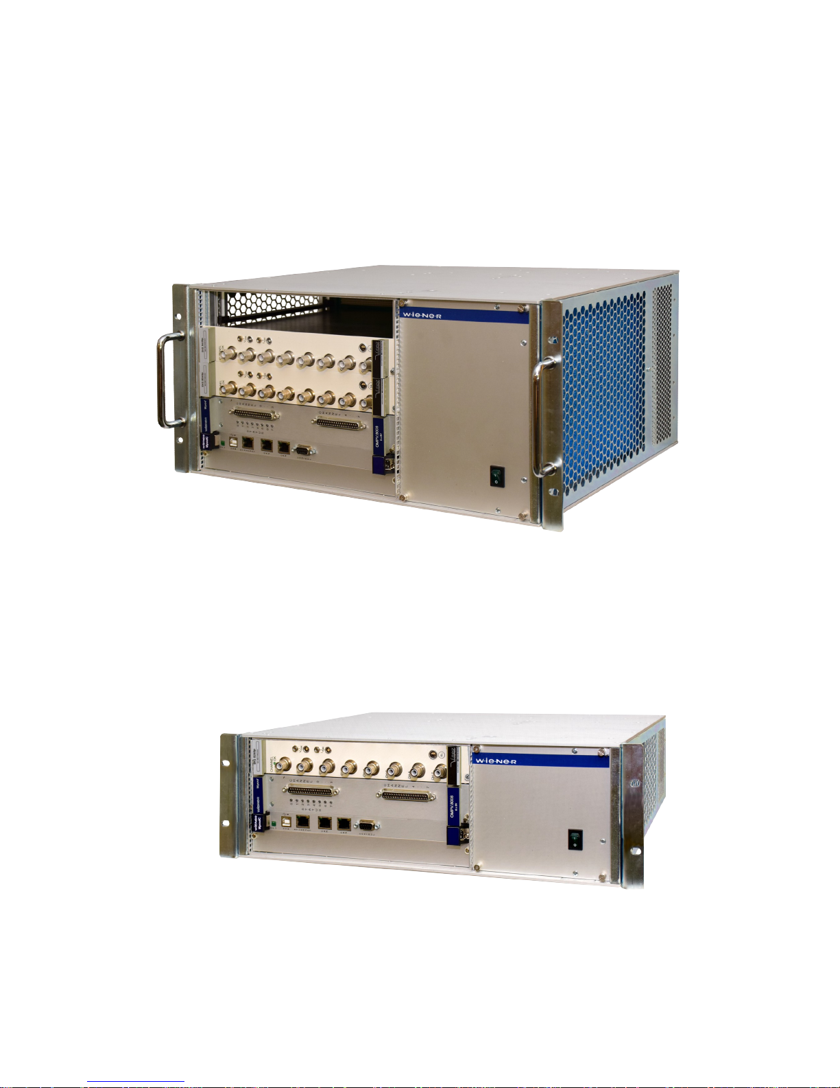
1.3 MPOD Mini crate
The WIENER MPOD mini crate represents a compact 19” rack mountable chassis for up to 4
MPOD low and high voltage modules. The MPOD mini crate includes the primary power supply
with 600W power for high voltage modules as well as a cooling system with high performance
DC fan. It can be outfitted with HV backplane for us as a high voltage system only or with both
HV and LV backplanes.
The first half slot is reserved for the MPOD Controller which manages the primary power
supplies and provides Ethernet, USB and CAN-bus interfaces for remote monitoring and control.
Please note that it is possible to switch the MPOD crate off and on off remotely when the front
panel switch is in ON position.
MPOD Mini crate with MPOD controller and 2 high voltage + 1 low voltage module
1.4 MPOD Micro crate
The MPOD micro crate is the smallest and low cost option for the WIENER multi-channel high
and low voltage power supply system. The MPOD micro mainframe can house 1 or 2 plug-in low
or high voltage modules. The integrated MPOD controller card provides10/100 Ethernet, CAN
bus and USB-2 interfaces.
MPOD micro_2 crate with MPOD controller ,one low voltage and one high voltage module
30. May 2018 8
Page 10
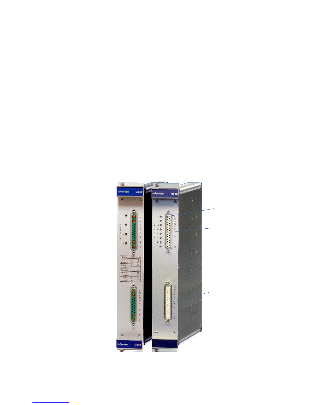
2 LV Modules
The MPV MPOD Low Voltage modules are available with either 4 or 8 channels for different voltage
ranges with 8V, 16V, 30V, 60V maximum respectively. Special modules with up to 120V are under
development. All MVP modules have the following features:
● 6U height, 220mm deep fully shielded mechanics
● All DC outputs with individual return lines, individually sensed, floating channel to channel and
channel to chassis ground (125V, 500V tested)
● Low noise and ripple (<3mV at 20MHz bandwidth)
● Voltage and current settings / monitoring for each channel, 15 bit resolution, accuracy +/-0.1% of
full scale value
● Current monitoring and limiting for each channel, 15 bit resolution, accuracy +/-0.05% of full
scale value
● high stability, 0.2%/10k
● Programmable channel parameters:
○ voltage, under voltage / over voltage trip point
○ current limit
○ power, regulation type, internal / externl sense
○ ramping speed up and down (1V/s … 500V/s)
○ group features / error handling
● programming and monitoring via Ethernet (TCP/IP) and USB
● Connectors: 2 x 8 pin high current sub-D, 37 pin sub-D for sense / control or
30. May 2018 9
Status LED's for allchannels
DC terminal and sense
channel 0 to 3
DC terminal and sense
channel 4 to 7
Page 11

2.1 MPOD Low Voltage Module Versions
MPOD Low Voltage Series - 8 channels with floating ground
Type Channels Voltage I Max Peak Power V-Res I-Res Ripple
MPV 4008I 4 0 to 8V 20A 100W/ ch. 0.5mV 0.5mA <3mVpp
MPV 8008I 8 0 to 8V 10A 50W / ch. 0.5mV 0.5mA <3mVpp
MPV 8008LI 8 0 to 8V 5A 40W / ch. 0.5mV 0.25mA <3mVpp
MPV 4016I 4 0 to 16V 10A 100W/ ch. 1mV 0.25mA <2mVpp
MPV 8016I 8 0 to 15V 5A 50W / ch. 1mV 0.25mA <2mVpp
MPV 4030I 4 0 to 30V 5A 100W/ ch. 2mV 0.12mA <2mVpp
MPV 8030I 8 0 to 30V 2.5A 50W / ch. 2mV 0.12mA <2mVpp
MPV 4060I 4 0 to 60V 2A 100W/ ch. 4mV 0.06mA <2mVpp
MPV 8060I 8 0 to 60V 1A 50W / ch. 4mV 0.06mA <2mVpp
MPV 8120I 8 0 to 120V 100mA 50W / ch. 4mV 4 µA <10mVpp
I = Interlock, with sub D 37 pin female connector.
MPOD Low Voltage mating connectors
Sub-D 37 extension cable 5m 37 Combined power/sense for 4 channels
Sub-D 37 extension cable 25m 37 Combined power/sense for 4 channels
Connectors are IEC807-3/DIN41652 conform. Custom made cable sets are available on request.
30. May 2018 10
Page 12
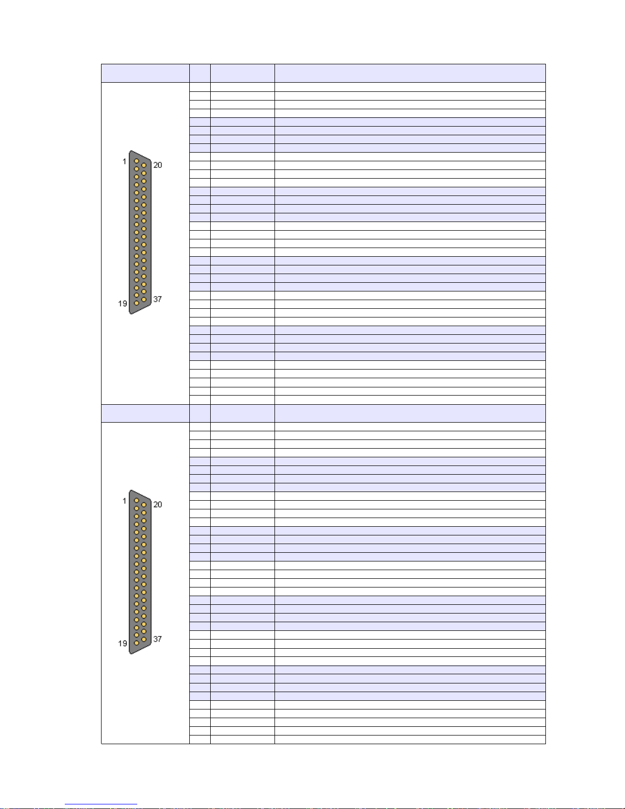
2.2 Combined Power & Sense Connector Pin Assignment MPV 8xxx(standard female type)
DSUB37 female
(Channel 0..3)
Pin Signal
2.2.1
U0-
Channel 0 negative output
20
U0+
Channel 0 positive output
2
U0-
Channel 0 negative output
21
U0+
Channel 0 positive output
3
U0-
Channel 0 negative output
22
U0+
Channel 0 positive output
4
S0-
Channel 0 negative sense input
23
S0+
Channel 0 positive sense input
5
U1-
Channel 1 negative output
24
U1+
Channel 1 positive output
6
U1-
Channel 1 negative output
25
U1+
Channel 1 positive output
7
U1-
Channel 1 negative output
26
U1+
Channel 1 positive output
8
S1-
Channel 1 negative sense input
27
S1+
Channel 1 positive sense input
9
U2-
Channel 2 negative output
28
U2+
Channel 2 positive output
10
U2-
Channel 2 negative output
29
U2+
Channel 2 positive output
11
U2-
Channel 2 negative output
30
U2+
Channel 2 positive output
12
S2-
Channel 2 negative sense input
31
S2+
Channel 2 positive sense input
13
U3-
Channel 3 negative output
32
U3+
Channel 3 positive output
14
U3-
Channel 3 negative output
33
U3+
Channel 3 positive output
15
U3-
Channel 3 negative output
34
U3+
Channel 3 positive output
16
S3-
Channel 3 negative sense input
35
S3+
Channel 3 positive sense input
17
INTERLOCK0
Optional interlock input: The four channels of this connector are
36
INTERLOCK1
enabled only if a signal is applied here
18
LOOP0
Safety Loop, LOOP0 and LOOP1 are connected to each other, no
37
LOOP1
connection to other potentials
19 CHASSIS Connected to chassis / front panel
SUB37 female
(Channel 4..7)
Pin Signal
Bottom Connector
1
U4-
Channel 4 negative output
20
U4+
Channel 4 positive output
2
U4-
Channel 4 negative output
21
U4+
Channel 4 positive output
3
U4-
Channel 4 negative output
22
U4+
Channel 4 positive output
4
S4-
Channel 4 negative sense input
23
S4+
Channel 4 positive sense input
5
U5-
Channel 5 negative output
24
U5+
Channel 5 positive output
6
U5-
Channel 5 negative output
25
U5+
Channel 5 positive output
7
U5-
Channel 5 negative output
26
U5+
Channel 5 positive output
8
S5-
Channel 5 negative sense input
27
S5+
Channel 5 positive sense input
9
U6-
Channel 6 negative output
28
U6+
Channel 6 positive output
10
U6-
Channel 6 negative output
29
U6+
Channel 6 positive output
11
U6-
Channel 6 negative output
30
U6+
Channel 6 positive output
12
S6-
Channel 6 negative sense input
31
S6+
Channel 6 positive sense input
13
U7-
Channel 7 negative output
32
U7+
Channel 7 positive output
14
U7-
Channel 7 negative output
33
U7+
Channel 7 positive output
15
U7-
Channel 7 negative output
34
U7+
Channel 7 positive output
16
S7-
Channel 7 negative sense input
35
S7+
Channel 7 positive sense input
17
INTERLOCK0
Optional interlock input: The four channels of this connector are
36
INTERLOCK1
enabled only if a signal is applied here
18
LOOP0
Safety Loop, LOOP0 and LOOP1 are connected to each other, no
37
LOOP1
connection to other potentials
19 CHASSIS Connected to chassis / front panel
30. May 2018 11
Page 13
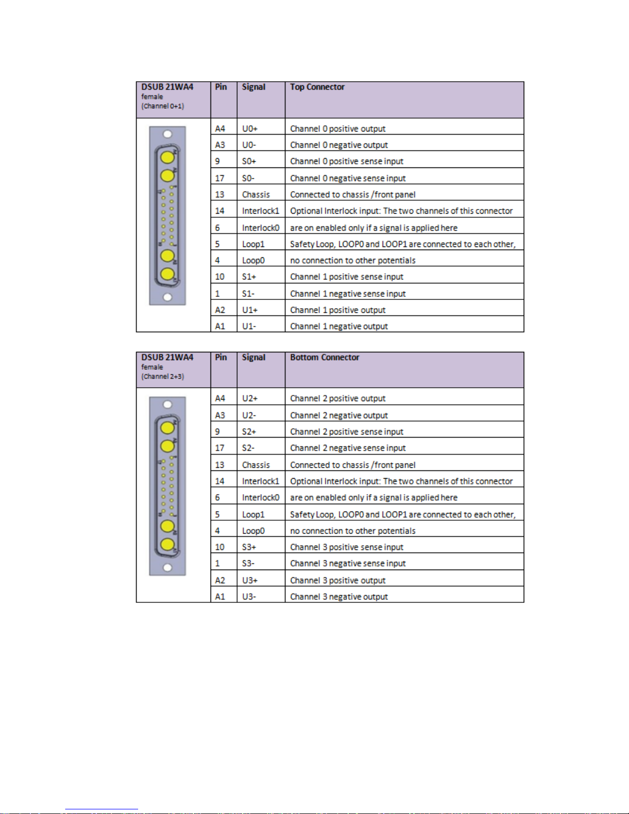
2.3 Power & Combined Power & Sense Connector 4 channel MPV4x xxI1
30. May 2018 12
Page 14
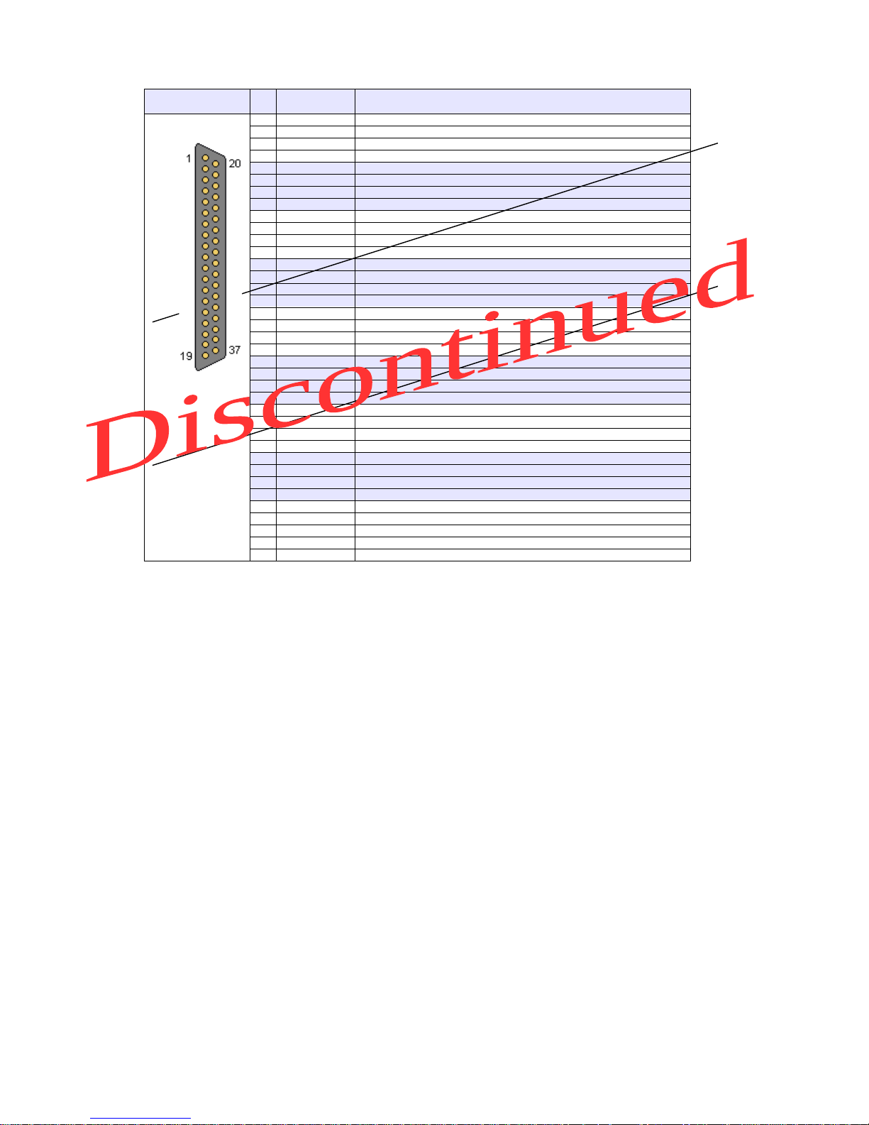
2.4 Sense & Control Connector Pin Assignment (modules with 8 channel + DSUB37-8)
DSUB37 male
(Channel 0..7)
Pin Signal Comment
1
S0+
Channel 0 positive Sense Input
20
S0-
Channel 0 negative Sense Input
2
reserved
21
reserved
3
S1+
Channel 1 positive Sense Input
22
S1-
Channel 1 negative Sense Input
4
reserved
23
reserved
5
S2+
Channel 2 positive Sense Input
24
S2-
Channel 2 negative Sense Input
6
reserved
25
reserved
7
S3+
Channel 3 positive Sense Input
26
S3-
Channel 3 negative Sense Input
8
reserved
27
reserved
9
S4+
Channel 4 positive Sense Input
28
S4-
Channel 4 negative Sense Input
10
reserved
29
reserved
11
S5+
Channel 5 positive Sense Input
30
S5-
Channel 5 negative Sense Input
12
reserved
31
reserved
13
S6+
Channel 6 positive Sense Input
32
S6-
Channel 6 negative Sense Input
14
reserved
33
reserved
15
S7+
Channel 7 positive Sense Input
34
S7-
Channel 7 negative Sense Input
16
reserved
35
reserved
17
reserved
36
reserved
18
reserved
37
reserved
19 reserved
Some pins are reserved for future funcionality
30. May 2018 13
Page 15
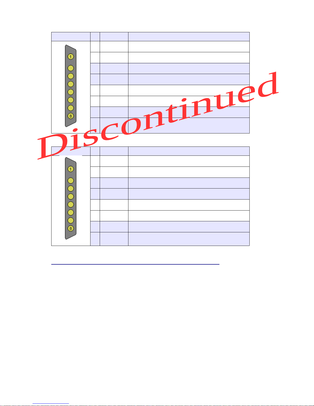
2.5 Power Connector Pin Assignment (modules with mixed DSUB37 + DSUB37-8)
DSUB37-8 female
(Channel 0..3)
Pin Signal Comment
1 U0+ Channel 0 positive Output
2 U0- Channel 0 negative Output
3 U1+ Channel 1 positive Output
4 U1- Channel 1 negative Output
5 U2+ Channel 2 positive Output
6 U2- Channel 2 negative Output
7 U3+ Channel 3 positive Output
8 U3- Channel 3 negative Output
DSUB37-8 female
(Channel 4..7)
Pin Signal Comment
1 U4+ Channel 4 positive Output
2 U4- Channel 4 negative Output
3 U5+ Channel 5 positive Output
4 U5- Channel 5 negative Output
5 U6+ Channel 6 positive Output
6 U6- Channel 6 negative Output
7 U7+ Channel 7 positive Output
8 U7- Channel 7 negative Output
Matching cable plug:
e.g. Erni TMC – P - 8W8 male, unloaded connector (103448) + pins:
http://www.erni.com/DB/PDF/TMC/ERNI-D-SubHighPower0101-e.pdf
30. May 2018 14
Page 16
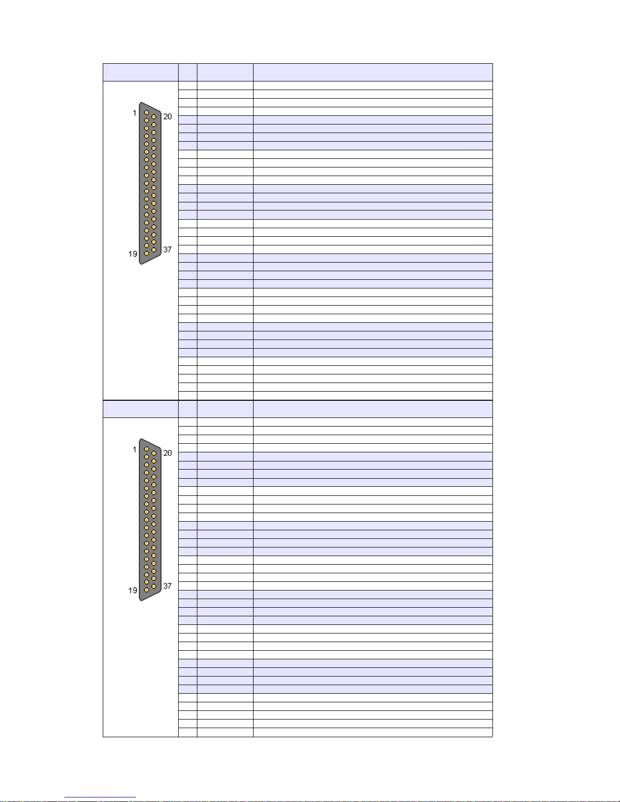
2.6 Combined Power & Sense Connector Pin Assignment MPV 4xxx (female 4 channel )
DSUB37 male
(Channel 0..3)
Pin Signal
Top Connector
1
S0+
Channel 0 positive Sense Input
20
S0-
Channel 0 negative Sense Input
2
reserved
21
reserved
3
S1+
Channel 1 positive Sense Input
22
S1-
Channel 1 negative Sense Input
4
reserved
23
reserved
5
S2+
Channel 2 positive Sense Input
24
S2-
Channel 2 negative Sense Input
6
reserved
25
reserved
7
S3+
Channel 3 positive Sense Input
26
S3-
Channel 3 negative Sense Input
8
reserved
27
reserved
9
S4+
Channel 4 positive Sense Input
28
S4-
Channel 4 negative Sense Input
10
reserved
29
reserved
11
S5+
Channel 5 positive Sense Input
30
S5-
Channel 5 negative Sense Input
12
reserved
31
reserved
13
S6+
Channel 6 positive Sense Input
32
S6-
Channel 6 negative Sense Input
14
reserved
33
reserved
15
S7+
Channel 7 positive Sense Input
34
S7-
Channel 7 negative Sense Input
16
reserved
35
reserved
17
reserved
36
reserved
18
reserved
37
reserved
19 reserved
DSUB37 male
(Channel 4..7)
Pin Signal
Bottom Connector
1
S0+
Channel 0 positive Sense Input
20
S0-
Channel 0 negative Sense Input
2
reserved
21
reserved
3
S1+
Channel 1 positive Sense Input
22
S1-
Channel 1 negative Sense Input
4
reserved
23
reserved
5
S2+
Channel 2 positive Sense Input
24
S2-
Channel 2 negative Sense Input
6
reserved
25
reserved
7
S3+
Channel 3 positive Sense Input
26
S3-
Channel 3 negative Sense Input
8
reserved
27
reserved
9
S4+
Channel 4 positive Sense Input
28
S4-
Channel 4 negative Sense Input
10
reserved
29
reserved
11
S5+
Channel 5 positive Sense Input
30
S5-
Channel 5 negative Sense Input
12
reserved
31
reserved
13
S6+
Channel 6 positive Sense Input
32
S6-
Channel 6 negative Sense Input
14
reserved
33
reserved
15
S7+
Channel 7 positive Sense Input
34
S7-
Channel 7 negative Sense Input
16
reserved
35
reserved
17
reserved
36
reserved
18
reserved
37
reserved
19 reserved
30. May 2018 15
Page 17
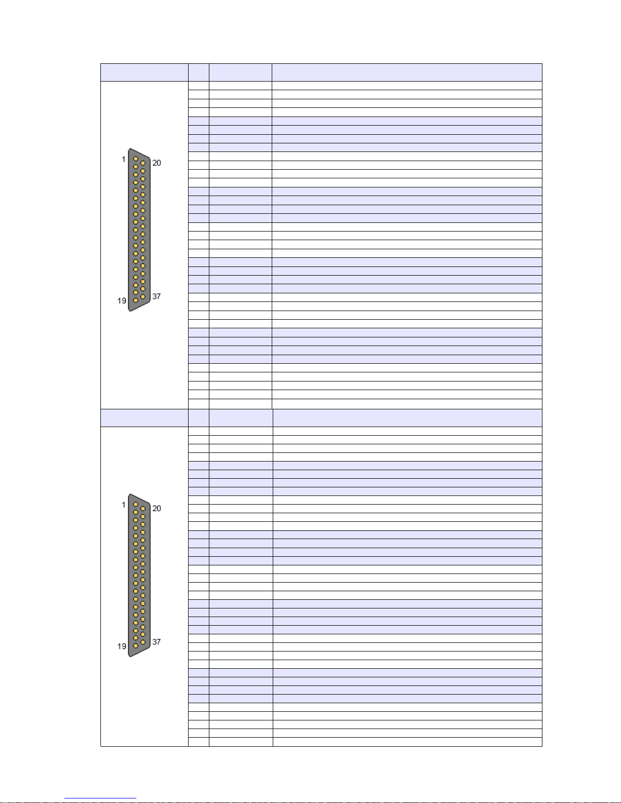
2.7 Combined Power & Sense Connector Pin Assignment MPV 2xxx (female 2 channel)
DSUB37 female
(Channel 0)
Pin Signal
Top connector
1 U0- Channel 0 negative output
20 U0+ Channel 0 positive output
2 U0- Channel 0 negative output
21 U0+ Channel 0positive output
3 U0- Channel 0 negative output
22 U0+ Channel 0 positive output
4 U0- Channel 0 negative output
23 U0+ Channel 0 positive output
5 U0- Channel 0 negative output
24 U0+ Channel 0 positive output
6 U0- Channel 0 negative output
25 U0+ Channel 0 positive output
7 U0- Channel 0 negative output
26 U0+ Channel 0 positive output
8 S0- Channel 0 negative sense input
27 S0+ Channel 0 positive sense input
9 U1- Channel 1 negative output
28 U1+ Channel 1 positive output
10 U1- Channel 1 negative output
29 U1+ Channel 1 positive output
11 U1- Channel 1 negative output
30 U1+ Channel 1 positive output
12 U1- Channel 1 negative output
31 U1+ Channel 1 positive output
13 U1- Channel 1 negative output
32 U1+ Channel 1 positive output
14 U1- Channel 1 negative output
33 U1+ Channel 1 positive output
15 U1- Channel 1 negative output
34 U1+ Channel 1 positive output
16 S1 - Channel 1 negative sense input
35 S1 + Channel 1 positive sense input
17 INTERLOCK0 Optional interlock input: The channel of this connector is
36 INTERLOCK1 enabled only if a signal is applied here
18 LOOP0 Safety Loop, LOOP0 and LOOP1 are connected to each other, no
37 LOOP1 connection to other potentials
19
CHASSIS Connected to chassis / front panel
DSUB37 female
(Channel 1)
Pin Signal
Bottom Connector
1
U2-
Channel 2 negative output
20
U2+
Channel 2 positive output
2
U2-
Channel 2 negative output
21
U2+
Channel 2 positive output
3
U2-
Channel 2 negative output
22
U2+
Channel 2 positive output
4
U2-
Channel 2 negative output
23
U2+
Channel 2 positive output
5
U2-
Channel 2 negative output
24
U2+
Channel 2 positive output
6
U2-
Channel 2 negative output
25
U2+
Channel 2 positive output
7
U2-
Channel 2 negative output
26
U2+
Channel 2 positive output
8
S2-
Channel 2 negative sense input
27
S2+
Channel 2 positive sense input
9
U3-
Channel 3 negative output
28
U3+
Channel 3 positive output
10
U3-
Channel 3 negative output
29
U3+
Channel 3 positive output
11
U3-
Channel 3 negative output
30
U3+
Channel 3 positive output
12
U3-
Channel 3 negative output
31
U3+
Channel 3 positive output
13
U3-
Channel 3 negative output
32
U3+
Channel 3 positive output
14
U3-
Channel 3 negative output
33
U3+
Channel 3 positive output
15
U3-
Channel 3 negative output
34
U3+
Channel 3 positive output
16
S3-
Channel 3 negative sense input
35
S3+
Channel 3 positive sense input
17
INTERLOCK0
Optional interlock input: The channel of this connector is
36
INTERLOCK1
enabled only if a signal is applied here
18
LOOP0
Safety Loop, LOOP0 and LOOP1 are connected to each other, no
37
LOOP1
connection to other potentials
19 CHASSIS Connected to chassis / front panel
30. May 2018 16
Page 18
2.8 SAFETY LOOP and optional INTERLOCK functionality of MPV modules
The SAFETY LOOP pins provide a closed connection between LOOP0 and LOOP1 in case the properly
wired DSUB37 connector is plugged into the MPV module. It does not have any functionality inside the
module!
The Interlock features is only available on MPV 8xxxI modules. Older or other modules that do not have
the "I" (interlock) in the part number / name , will not interlock. Furthermore the interlock will work on the
bank of 4 channels on each sub-d 37 pin connector.
Using a 5-14V source, apply +V to pin 36 and 0V to pin 17 of the MPOD module sub-d 37 pin connector
(see pin layout in chapter 2.2).
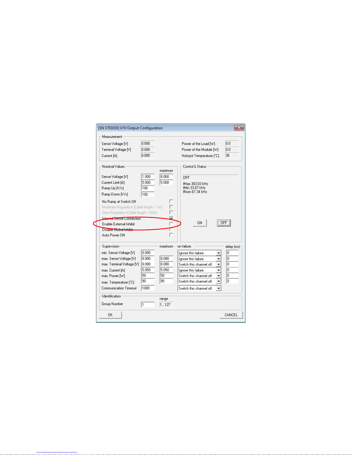
In order to use the Interlock function each channel has to be enabled for this. In MUSEcontrol Software,
right mouse click on the channel and check in the “Output Configuration” window the check mark “Enable
External Inhibit” accordingly.
30. May 2018 17
Page 19
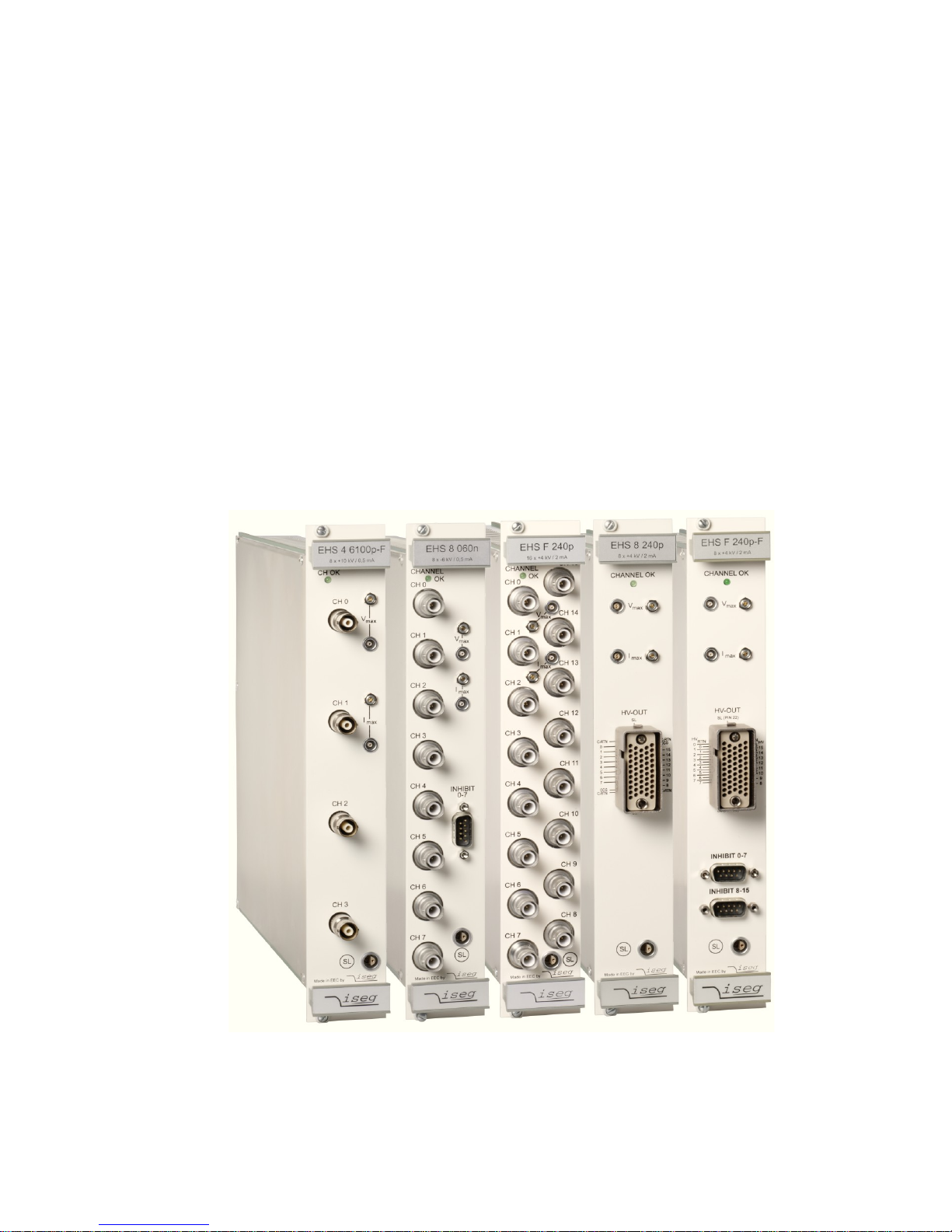
3 HV Modules
MPOD high voltage modules are manufactured by ISEG (www.iseg-hv.com). For technical
details please refer to the ISEG manuals and data sheets of the EHS, EBS, EDS and EHQ
(discontinued) multi channel high voltage modules. General features are:
● High Voltage modules with 4, 8, 16, 24, 32 or 48 individually controlled channels
● Maximum voltage range from 500V up to 10 kV
● Extremely low noise and ripple: <5mVpp to <10mVpp
● All DC outputs floating or common ground depending on module type
● Voltage and current settings / monitoring for each channel, 16 to 21 bit resolution
● Current monitoring and limiting for each channel, 16 to 21 bit resolution
● Programmable channel parameters, group features
● output connectors:
8 channel modules SHV or REDEL (<4kV) multi pin
Kings for 8kV and 10kV (4 channels only)
16 channel modules SHV or REDEL (<4kV) multi pin
24 channel modules REDEL (<4kV) multi pin or AMP 201311-3
32 channel modules REDEL multi pin
48 channel modules RADIAL multi-pin
ISEG high voltage modules with 4 channels KINGS (10kV), 8 and 16 channels SHV, and 8 / 16 channels
REDEL multi-pin connectors (from left to right)
30. May 2018 18
Page 20
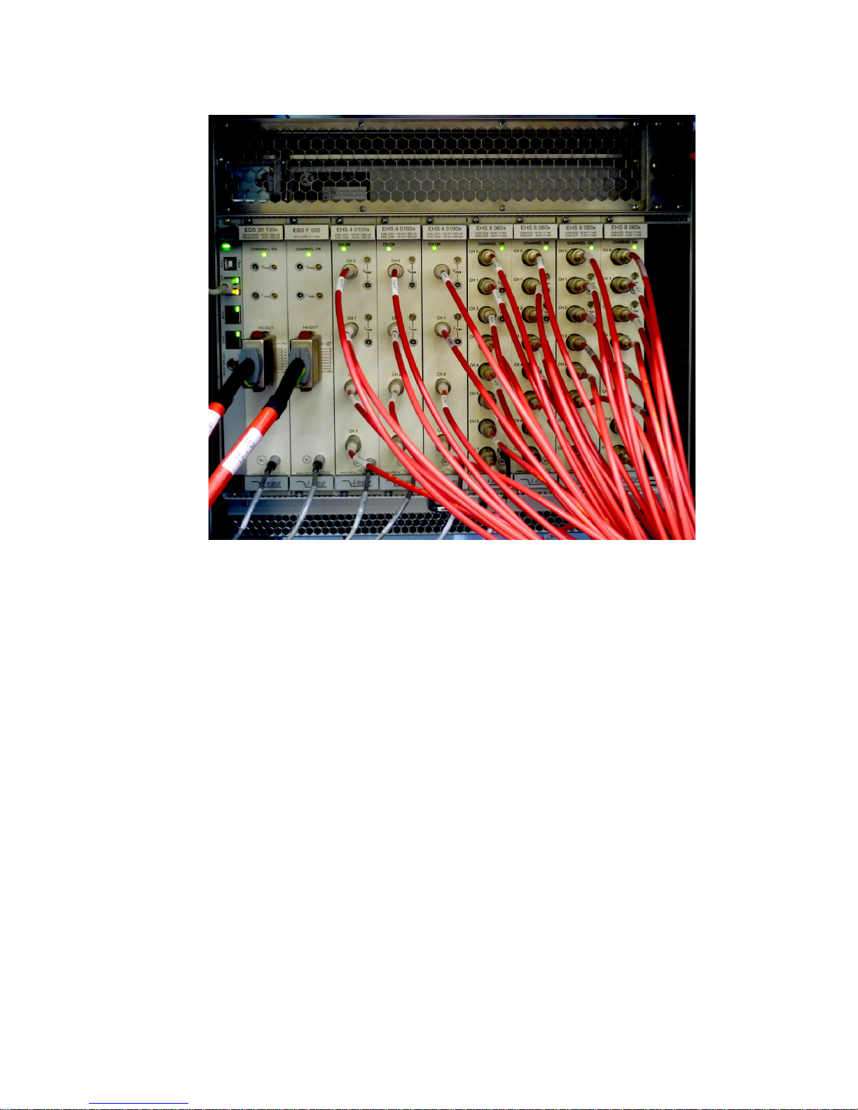
MPOD crate with rear side module option and air filter outfitted with ISEG EDS, EBS and EHS high
voltage modules and wired safety loop.
30. May 2018 19
Page 21
4 MPOD Controller
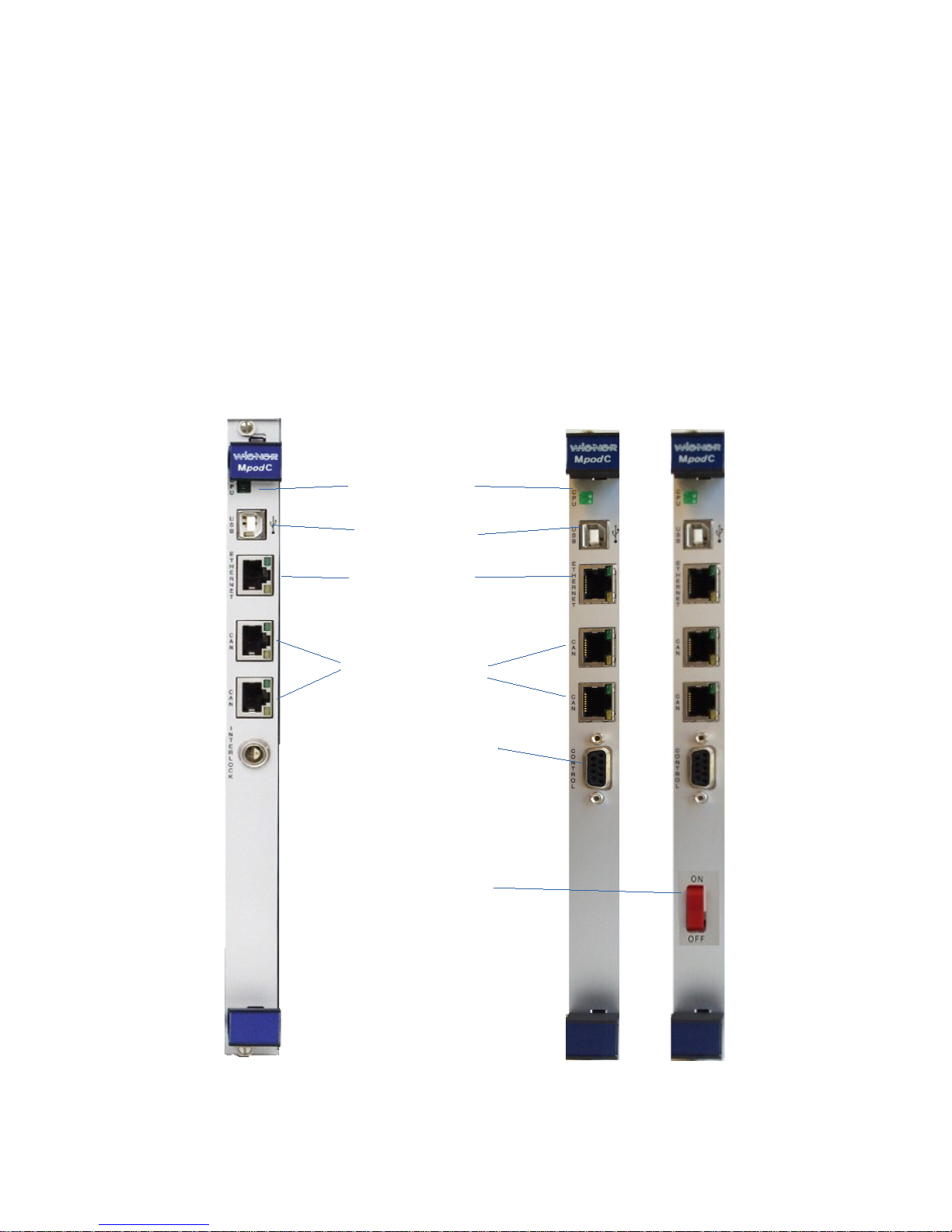
The MPOD controller which is plugged into the first half slot of the crate controls the primary power
supply as well as all inserted LV- and HV-modules. Further it connects these to remote controlling
interfaces / services in an unique way.
MPOD Controller features:
● TCP/IP 10M/100M port, auto ranging
● Built-in HTTP server
● TCP/IP protocol with SNMP v.2c for full control of all module parameters
● 2 CAN-Bus ports, wired in parallel for daisy-chaining
● USB 2 interface
● 3 status LED's
● Interlock connector (9pin DSUB)
Old Controller MpodC MpodC with ON/OFF
30. May 2018 20
Status LED's
USB 2 port
Ethernet port
2 CANbus ports
Interlock connector
9-pin SUBD
ON-OFF button
Page 22
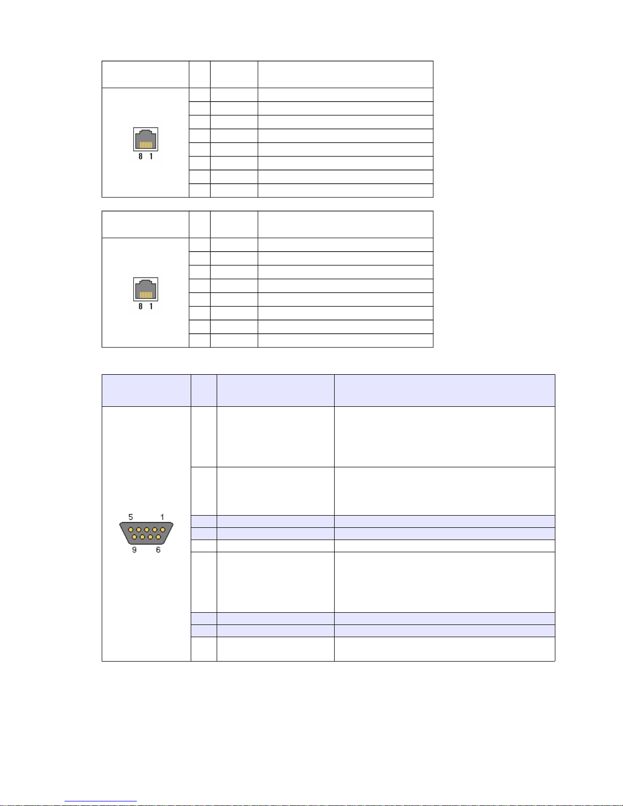
Ethernet port, standard NIC pin layout
RJ45 PinSignal Comment
1 TX+
2 TX3 RX+
4 GND 1 75 Ohm
5 GND 1
6 RX7 GND 2 75 Ohm
8 GND 2
CAN-bus ports
RJ45 PinSignal Comment
1 CAN-H
2 CAN-L
3 GND
4 n.c.
5 n.c.
6 reserved
7 GND
8 n.c.
Interlock connector
DSUB9 female Pin Signal Comment
1 CRATE_ENABLE
TTL input (1 kOhm resistor to GND)
A high level allows the channels to be switched on
by software
A low level forces all channels to switch off with
their specified down ramp.
2 CRATE_FAST_OFF
TTL input (1 kOhm resistor to GND)
A high level forces all channels to switch off as
fast as possible. Any ramp-down settings are
ignored.
3 reserved
4 reserved
5 GND Ground reference
6 CRATE_STATUS
TTL output (1 kOhm resistor to GND, 100 Ohm
resistor to protect the output buffer)
This signal is driven high, if one or more channels
of the MPOD system do have a non-zero output
voltage
7 reserved
8 reserved
9 (TTL High)
TTL high reference (only for FW 2.1.2607.1 and
higher
For set-up of Interlock please use MUSEcontrol in admin mode and enable / disable the Interlock
by removing or setting the flag “IGNORE HARDWARE INTERLOCK” in the configuration tab.
30. May 2018 21
Page 23
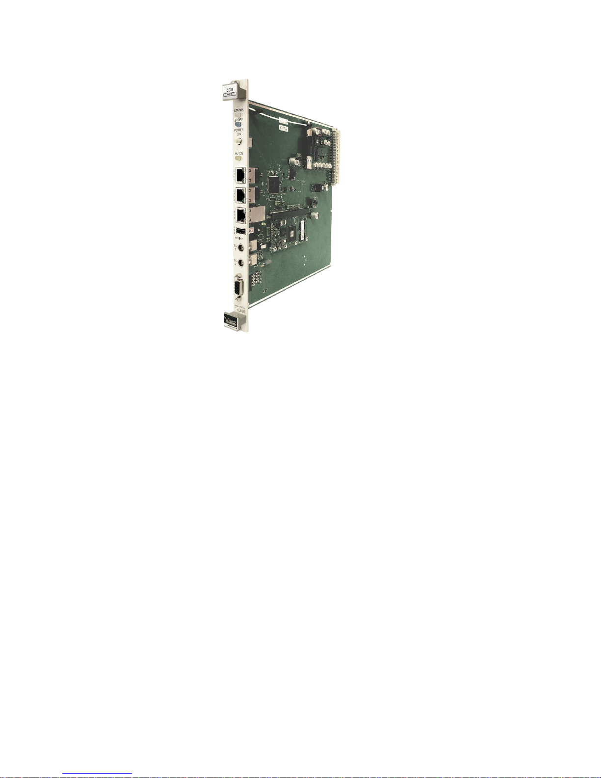
5 CC24 Controller (optional Controller istead of MpodC)
The iseg CC 24 series is an intelligent embedded Linux-Server system with preinstalled
iseg Communication Server (iCS). The iCS comes with a large set of preconfigured
services as EPICS, Web-Control, SNMP, SOAP, Websocket, OPC/UA1, isegHAL and
HTTP-API. The iCS also delivers two main web based user applications. iCScontrol
provides a quick and smart control interface of the connected hardware by using webbrowser without software installation. iCSconfig is used for hardware and service
configuration and firmware upgrades. Both can also be run on mobile devices like tablets
or smartphones. For native application control several software solutions are available:
iseg SNMP Control
isegControl (Linux, Windows, Mac)
isegHalRemote-Library
Ethernet and WiFi (opt.) connectivity
Master (CC24) / Slave (CC23) versions available
Embedded Linux-Server with iCS control system (Master version)
Two independent CAN extension ports (for Slave connection)
Controls crate and module functions
Digital I/O: Free configurable INHIBIT, INTERLOCK
Preconfigured services: EPICS, SNMP, HTTP, SOAP, Websocket
Webbrowser based control and configuration system
Easy configuration and firmware updates of connected hardware
For more details please see controller manual:
http://file.wiener-d.com/documentation/MPOD/iseg_manual_CC2x_en_14.pdf
30. May 2018 22
Page 24

6 Local Control
6.1 Introduction
MPOD full size and MPOD mini crates can be optionally equipped with a local color graphic
display and two rotary controls.
6.2 Usage of the rotary controls
Please note that the display function and operation changed with MPOD firmware 2.1.xxxx
Connecting MPOD to the AC line will show the following screen:
Switching POWER on will power up the MPOD crate and the display will scan the crate for available
module.
The two rotary knobs can be rotated and pushed. The right/upper* one controls vertical selections (e.g. to
scroll down a menu task or increase/decrease a operating value), while the left/lower* one controls the
horizontal selections (e.g. select other menus or sub-menus). By pushing the right/upper* knob (OK) it is
possible to select a menu item or to confirm input By pushing the left/lower* knob (CANCEL) it is
possible to escape from input fields.
Cancel OK
*concerns Mpod Mini, Mpod Micro
30. May 2018 23
Page 25
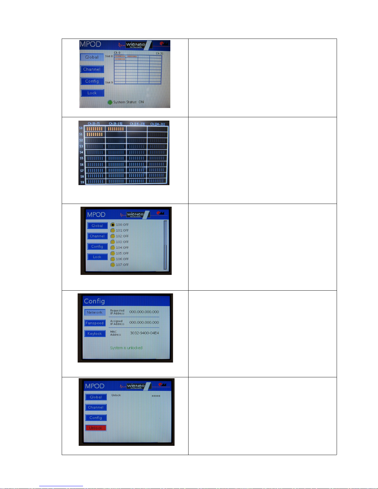
6.3 MPOD Display Main menu
Main Window
• Rotate <R> to change between GLOBAL,
CHANNEL,CONFIG and LOCK
Global Window
• Press <R> to go into screen saver mode with
high visibilitly channel display
• Press <L> to go back to the Main Window
Channel Window
• Press <R> to enter menu to access power
supply channels
• Press <L> to go back to the GLOBAL Window
CONFIG Window
• Press <R> to enter menu to change network
settings ,fan speed and to change Keylock
Password
• Press <L> to go back to the GLOBAL Window
VIEW LOCK
• Press <R> to enter menu to activate the
Keylock
• Press <L> to go back to the Main Window
30. May 2018 24
Page 26
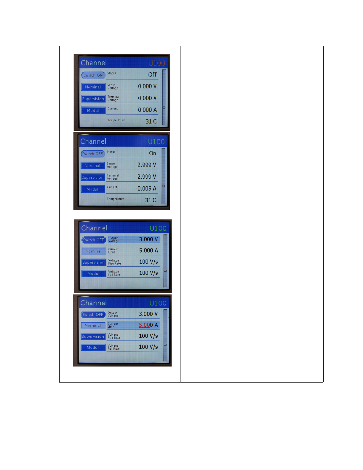
6.4 MPOD Display CHANNEL menu
SWITCH ON / OFF and status Window
• Press <R> to switch channel ON or OFF
• Rotate <R> to change between SWITCH
ON/OFF, NOMINAL ,SUPERVISION and
MODUL
NOMINAL settings Window
• Press <R> to select parameter (will be marked)
• Rotate <R> to change between Output
Voltage, Current Limit or Voltage ramps
• Press <R> to edit value (will be shown in red),
change value with <R>, <L> will change
resolution digits (red) to allow precise settings
• Press <R> save new values or <L> to discard
(cancel)
30. May 2018 25
Page 27
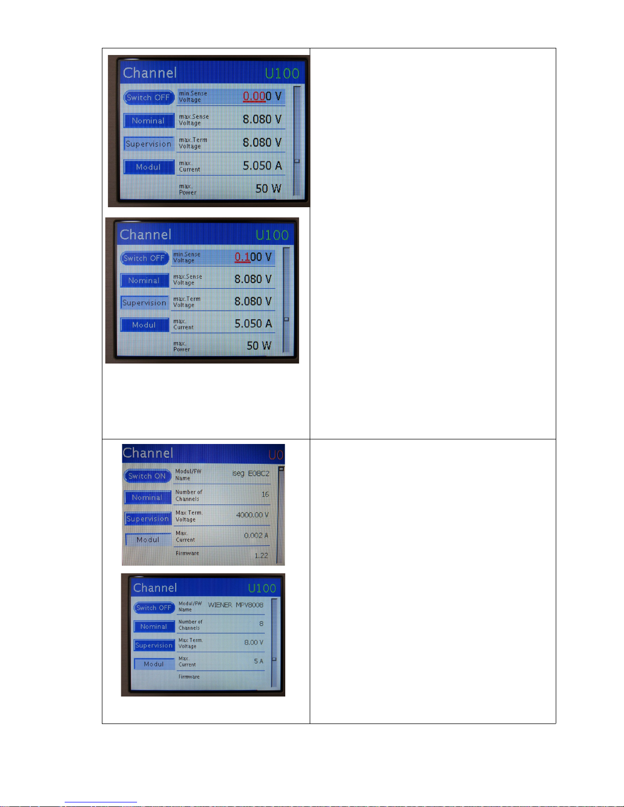
Supervision settings Window
• Press <R> to select parameter (will be marked
yellow)
• Rotate <R> to change between parameters
• Press <R> to edit value (will be shown in red),
change value with <R>, <L> will change
resolution digits (red) to allow precise settings
• Press <R> save new values or <L> to discard
(escape)
• Rotate <L> to go back (left) or to select another
channel (right) which will mark right button
yellow, channel then can be changed with <R>
MODUL Window
• EHS Module example values
• MPV Module example values
30. May 2018 26
Page 28
7 Remote Control / Software
Please check the download section at file.wiener-d.com for the latest version of MPOD
software and documentation!
7.1 Software Setup for Microsoft Windows
Before the MPOD Controller can be used, it may have to be configured according to the network
environment. The factory default configuration is DHCP.
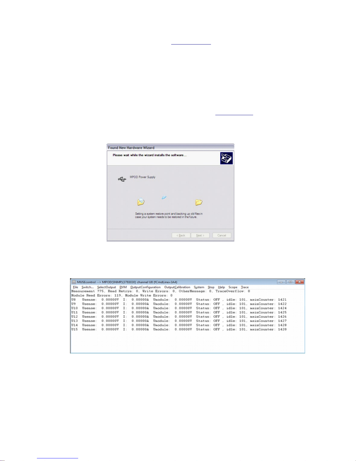
This is done locally via display or by running the MUSEcontrol utility, which allows access via
the USB-port of the MPOD Controller with a computer running 32-bit Windows XP, VISTA or
Windows 7.
Please download the latest version from the download area at file.wiener-d.com. Run the latest
MUSEcontrolInstall program to install all drivers and the USB program itself. It is recommended to define
a short path for the driver location during installation. Connecting the MPOD Controller via USB it should
be automatically detected and the Silicon Labs USB drivers (SiLib.sys and SiUSBXp.sys) loaded
Starting the program, the main window gives a quick overview of the MPOD and its connected
MPV low voltage modules. Please note that the MPOD crate has to be switched on in order to
show the low voltage modules!
In case no low voltage modules are located in the crate an error message “No module found” will pop up
which should be ignored. Note, all ISEG high voltage modules will not be shown and can not be controlled
via USB!
To prepare the MPOD controller select System → Configuration which starts the network configuration
dialog as shown below. Here you enter the TCP/IP network settings (IP address, subnet mask and default
gateway). You have to use the parameters of your local network here. Please contact your network
administrator for details. In order to use DHCP (factory default) an I address of 0.0.0.0 has to be selected.
30. May 2018 27
Page 29
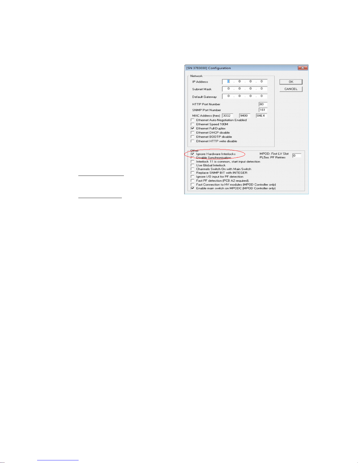
IP address of 0.0.0.0 will enable DHCP.
HTTP and SNMP port numbers should only be
modified if you know what you do. Setting any
ports to 0 disables the server.
The “First LV Slot” item is only used on old
systems / FW versions to define the slot number
of the first LV-module. Any HV-module plugged
into this slot will not be detected. (This setting is
necessary only for older MPOD firmware
versions and older MPV modules without
automatic detection of their slot numbers)
Enable / Disable MPOD controller interlock
Run MUSEcontrol program in admin mode:
"C:\Program Files\W-IE-NER\MUSEcontrol\MUSEcontrol.exe" USB
0x224
• Disable Interlock (Default): check
mark “Ignore Hardware interlock”
should be set
• Enable Interlock : remove check mark
“Ignore Hardware interlock”
Another essential menu item is the System → FirmwareUpdate which starts the firmware update
(see appendix A).
Low Voltage channels can be completely programmed and monitor within the MUSE application.
You can switch on or off any channel by clicking at the line of the channel. If you click with the
right mouse button, the “OutputConfiguration” dialog is entered:
Enable / Disable fast connection to HV modules
The standard Mpod Controller CAN- BUS communication speed is set to 125kb/s if you enable
the checkbox the communication speed will change to 250kb/s
Enable / Disable main Switch on MpodC
Enabled checkbox are for the newer Versions of our Mpod System with integrated Main Switch
in the Front Panel of the Controller .
Disabled checkbox are for all other Mpod Systems with Main Switch on the Crate Frontpanel
30. May 2018 28
Page 30
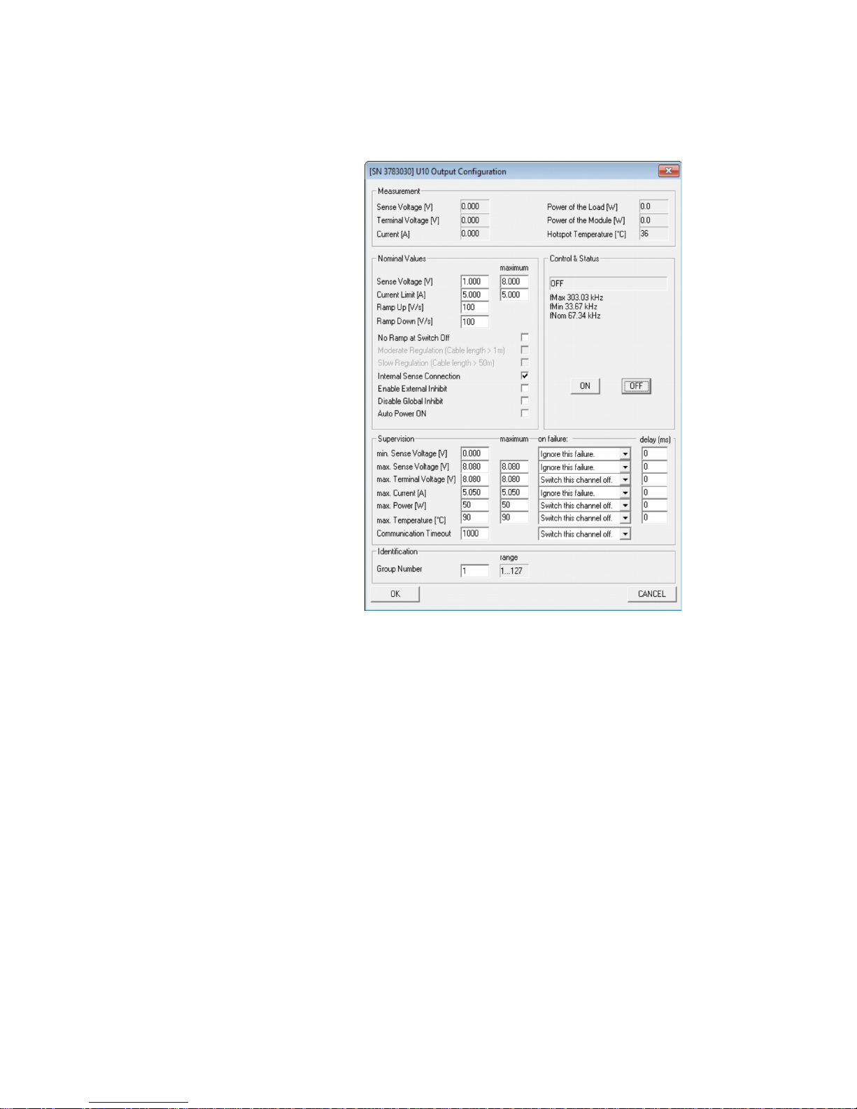
The dialog is divided into five main sections:
● Measurement
Shows the actual
measured sense voltage,
terminal voltage (at the
module terminals),
current, the calculated
power and the most
critical module
temperature.
● Control & Status
Here the channel can be
switched on and off. If
the channel has switched
off because of any failure,
the reason is displayed
here, too.
● Nominal Values
Here the nominal output
voltage (sense voltage),
current limit and ramping
speeds are entered. The
“No Ramp at Switch Off”
check box forces
immediate switch off.
The regulation mode can
be optimized for different
cable lengths (slow
regulation requests both check boxes to be checked!)
We recommend to activate the “Internal sense connection” checkbox if no external sense
line is connected on the output
● Supervision
Here the threshold values of the minimum sense voltage, the maximum sense voltage, the
maximum terminal voltage, the maximum current, the maximum power, the maximum
temperature and the communication timeout can be entered. The right column “maximum”
can only be changed by this utility and is the maximum allowed value of the left column.
The left column may be changed here or via the TCP/IP network.
The most right column “on failure” defines the action if the associated threshold is
exceeded.
The “communication timeout” at the last row is an internal timeout of the communication
between different processors. If the processor responsible for a specific output has no data
from it's master processor for longer than this time (in milliseconds), the output channel
will be switched off.
● Identification
Here the group number of this channel can be entered.
Other main menu items associated with this dialog are “Start/Stop” (stop and restart the
communication with the MPOD controller via USB) and “SelectOutput”, which simple
increments the channel number which is displayed by the other dialogs.
The other main menu items are used for test and maintenance and should not used by the customer.
30. May 2018 29
Page 31
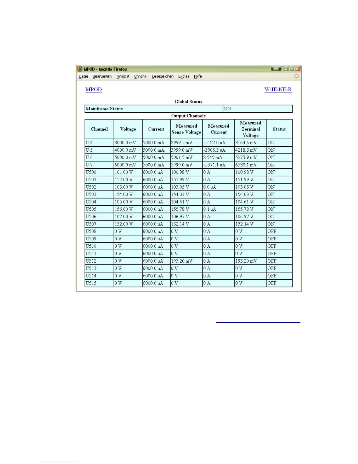
7.2 Web Browser
With a web browser pointing to the IP address as URL it is possible to get an overview of all
channels in a simple way.
7.3 NetSNMP
NetSNMP is an open source SNMP program which can be used to access the MPOD controller
via the Simple Network Management Protocol. Please see http://net-snmp.sourceforge.net/ for
more details.
Please install netSNMP (32-bit version) from the CD-ROM or downloaded from WIENER
support web site on the control computer. In order to perform SNMP calls from any WIENER
product the WIENER-CRATE-MIB file must be stored somewhere on the PC doing the calls, by
default that location should be /usr/share/snmp/mibs (Windows: C:\usr\share\snmp\mibs).
The most commonly used net-snmp calls are:
snmpwalk – returns groups of parameters / items
snmpget – returns a specific parameter (read)
snmpset – sets a specific parameter (write)
Please see the Net-snmp description and help files for detailed instructions and options. All
parameters defined for the WIENER MPOD system as well as crates and other power supplies are
contained within the WIENER-CRATE-MIB.txt file (see description in there!).
30. May 2018 30
Page 32

The following community groups are used:
“public”: for all read operations
“private”: to switch crate on or off
“admin”: to change parameters as fan speed or temperature limits
“guru”: to change HV and LV channel parameters as voltages, current limits, ramps, ...
A fast an easy way to begin using SNMP is to use command line arguments. The command line
arguments specified in this document are based on netSNMP. The command line syntax is the
same for both windows and Linux (and probably MAC OSX).
For all WIENER-CRATE-MIB library calls a quick help text can be shown by using
snmptranslate -On -Td WIENER-CRATE-MIB::xxxx
snmptranslate -On -Td WIENER-CRATE-MIB::outputName
.1.3.6.1.4.1.19947.1.3.2.1.2
outputName OBJECT-TYPE
-- FROM WIENER-CRATE-MIB
-- TEXTUAL CONVENTION DisplayString
SYNTAX OCTET STRING (1..4)
DISPLAY-HINT "255a"
MAX-ACCESS read-only
STATUS current
DESCRIPTION "A textual string containing a short name of the
output. If the crate is equipped with an alphanumeric
display, this string is shown to identify a output channel."
::= { iso(1) org(3) dod(6) internet(1) private(4) enterprises(1) wiener(19947) c
rate(1) output(3) outputTable(2) outputEntry(1) 2 }
A first communication with the MPOD crate can be done using the snmpwalk to confirm the
existence of the power supply at the given IP address.
snmpwalk -Cp -Oqv -v 2c -M $path -m +WIENER-CRATE-MIB -c public $ip
with:
snmpwalk: This command will retrieve a block of information.
-v 2c: This parameters specifies which version of the SNMP to use. WIENER devices use
SNMP 2C.
-M $path: This parameter should be replaced with the path to the WIENER-CRATE-
MIB.txt file. It is not needed in case the default path is used.
-m +WIENER-CRATE-MIB: This parameter tells the command to look at the WIENER-
CRATE-MIB to resolve the OID name.
-c public: This specifies which community of values can be accessed.
$ip: This should be replaced with the IP address of the MPOD crate.
Example for crate with IP address 192.168.2.25:
snmpwalk -v 2c -m +WIENER-CRATE-MIB -c public 192.168.2.25
returns:
30. May 2018 31
Page 33

SNMPv2-MIB::sysDescr.0 = STRING: WIENER MPOD (4193086, MPOD 1.1.1.6,
MPODslave 1.06)
SNMPv2-MIB::sysObjectID.0 = OID: WIENER-CRATE-MIB::sysMainSwitch.0
SNMPv2-MIB::sysUpTime.0 = Timeticks: (13401) 0:02:14.01
SNMPv2-MIB::sysContact.0 = STRING:
SNMPv2-MIB::sysName.0 = STRING:
SNMPv2-MIB::sysLocation.0 = STRING:
SNMPv2-MIB::sysServices.0 = INTEGER: 79
A list of all available parameters or sub-parameters as for instance channels can be obtained using
the command snmpwalk with the paramtere “crate”. To get all parameters use:
snmpwalk -Cp -Oqv -v 2c -M $path -m +WIENER-CRATE-MIB -c public $ip crate
example:
snmpwalk -v 2c -m +WIENER-CRATE-MIB -c public 192.168.2.25 crate
Further it is possible obtain the array of names or values for a specific parameter. The following
command provides a list of all existing output channels:
snmpwalk -Cp -Oqv -v 2c -M $path -m +WIENER-CRATE-MIB -c public $ip outputName
Example:
snmpwalk -v 2c -m +WIENER-CRATE-MIB -c public 192.168.2.25 outputName
returns for MPOD system with 2 ISEG EHS HV modules (8 channels each) in slot 2 and 3:
WIENER-CRATE-MIB::outputName.u100 = STRING: U100
WIENER-CRATE-MIB::outputName.u101 = STRING: U101
WIENER-CRATE-MIB::outputName.u102 = STRING: U102
WIENER-CRATE-MIB::outputName.u103 = STRING: U103
WIENER-CRATE-MIB::outputName.u104 = STRING: U104
WIENER-CRATE-MIB::outputName.u105 = STRING: U105
WIENER-CRATE-MIB::outputName.u106 = STRING: U106
WIENER-CRATE-MIB::outputName.u107 = STRING: U107
WIENER-CRATE-MIB::outputName.u200 = STRING: U200
WIENER-CRATE-MIB::outputName.u201 = STRING: U201
WIENER-CRATE-MIB::outputName.u202 = STRING: U202
WIENER-CRATE-MIB::outputName.u203 = STRING: U203
WIENER-CRATE-MIB::outputName.u204 = STRING: U204
WIENER-CRATE-MIB::outputName.u205 = STRING: U205
WIENER-CRATE-MIB::outputName.u206 = STRING: U206
WIENER-CRATE-MIB::outputName.u207 = STRING: U207
This example returns 16 index numbers. Please note the following geographic module and
channel number coding for the SNMP call indexes, where the first digit is defined by the slot
number and the following two by the channel of the particular module in this slot:
Slot Channel Name index
1 0 to 99 Uxx .u00 to .u99
2 0 to 99 U1xx .u100 to .u199
... ... ... ...
10 0 to 99 U9xx .u901 to .u999
Please note that both the index as well as the name can be used!
30. May 2018 32
Page 34

snmpget -v 2c -m +WIENER-CRATE-MIB -c public 192.168.0.80 outputVoltage.u0
WIENER-CRATE-MIB::outputVoltage.u0 = Opaque: Float: 123.000000 V
is identical to
snmpget -v 2c -m +WIENER-CRATE-MIB -c public 192.168.0.80 outputVoltage.1
WIENER-CRATE-MIB::outputVoltage.u0 = Opaque: Float: 123.000000 V
In case of multi crate system there will be an additional digit for the crate number:
Name = 1000 * crate + 100*slot + channel
index = 1000 * crate + 100*slot + channel
(crate: 0 .... 9, slot: 0 ... 9 , channel: 0 ... 99)
To see all 0utput channel set voltage values use snmpwalk with outputVoltage:
snmpwalk -Cp -Oqv -v 2c -M $path -m +WIENER-CRATE-MIB -c public $ip
outputVoltage
Example:
snmpwalk -v 2c -m +WIENER-CRATE-MIB -c public 192.168.2.25 outputVoltage
returns for a MPOD system with one 8 channel ISEG EHS HV module in slot 3:
WIENER-CRATE-MIB::outputVoltage.u200 = Opaque: Float: 0.000000 V
WIENER-CRATE-MIB::outputVoltage.u201 = Opaque: Float: 0.000000 V
WIENER-CRATE-MIB::outputVoltage.u202 = Opaque: Float: 0.000000 V
WIENER-CRATE-MIB::outputVoltage.u203 = Opaque: Float: 0.000000 V
WIENER-CRATE-MIB::outputVoltage.u204 = Opaque: Float: 0.000000 V
WIENER-CRATE-MIB::outputVoltage.u205 = Opaque: Float: 0.000000 V
WIENER-CRATE-MIB::outputVoltage.u206 = Opaque: Float: 0.000000 V
WIENER-CRATE-MIB::outputVoltage.u207 = Opaque: Float: 0.000000 V
After obtaining information about the power supplies or a list of channels and parameters, it is
useful to be able to write or read information about it. This can be done using the snmpget and
snmpset commands.
snmpget -Oqv -v 2c -M $path -m +WIENER-CRATE-MIB -c guru $ip name.index
snmpset -v 2c -M $path -m +WIENER-CRATE-MIB -c guru $ip name.index format value
The most common kind of call you will want is to get data from the power supply. This is easily done via
the snmpget command. The example below retrieves information about whether the main power for the
crate is on. If you wish to test this example on your own system replace “$path” with the path to WIENERCRATE-MIB.txt (/usr/share/snmp/mibs by default and “$ip” with the ip address of your MPOD (see
following examples).
snmpget -v 2c -M $path -m +WIENER-CRATE-MIB -c public $ip sysMainSwitch.0
WIENER-CRATE-MIB::sysMainSwitch.0 = INTEGER: OFF(0)
This indicates that the MPOD crate is currently off. To better understand the call above we will
break it down by parameter:
snmpget: This command will retrieve a value about the MPOD crate or one of the
channels it houses..
-v 2c: This parameters specifies which version of the SNMP to use. WIENER devices use
SNMP 2C.
-M $path: This parameter should be replaced with the path to the WIENER-CRATE-
30. May 2018 33
Page 35

MIB.txt file.
-m +WIENER-CRATE-MIB: This parameter tells the command to look at the WIENERCRATE-MIB to resolve the OID name.
-c public: This specifies which community of values can be accessed.
$ip: This should be replaced with the IP address of the MPOD crate.
sysMainSwitch.0: This is the register you wish to retrieve.
Since we we know from the call above that the crate is off, we may want to turn it on. (Software
power cycling is only possible of the green mains switch on the MPOD is “ON”, this is to prevent
a remote user to override a local user and adds a level of safety to the unit.) To turn MPOD on, we
can use the command:
snmpset -v 2c - path -m +WIENER-CRATE-MIB -c private $ip sysMainSwitch.0 i 1
Most of the parameters for snmpset are the same as snmpget, the new parameters are highlighted
below.
i: Since sysMainSwitch.0 is an integer value, we specify the value to be an integer with.
1: This is the value we wish to write. In this case we write ‘one’ to set the main switch to
on.
For most of the write commands (snmpset) the access type has to be changed from public to guru.
A complete list of value names that can be written or read via SNMP can be found in the
WIENER-CRATE-MIB but commonly needed values are (see full list in chapter 6.10):
Value Name Type Access Comments
outputVoltage Float R/W The Channel set Voltage
outputCurrent Float R/W The channel current limit
outputMeasurementSenseVoltageFloat R Actual channel Voltage at sense
line
outputMeasurementTerminalV
oltage
Float R Actual channel Voltage at
terminal
outputMeasurementCurrent Float R Actual channel current
outputSwitch Integer R/W Turns channel ON / OFF,
emergency off, reset error flags
outputVoltageRiseRate Float R/W Channel ramp rate up
outputVoltageFallRate Float R/W Channel ramp rate down
outputStatus Bits R Channel Status information
For example, to read channel set voltage use:
snmpget -Oqv -v 2c -M $path -m +WIENER-CRATE-MIB -c guru $ip outputVoltage.index
Example:
snmpget -v 2c -m +WIENER-CRATE-MIB -c public 192.168.2.25 outputVoltage.u0
WIENER-CRATE-MIB::outputVoltage.u0 = Opaque: Float: 0.000000 V
30. May 2018 34
Page 36

Write and read individual set voltages, “guru” access needed to write!
snmpset -v 2c -m +WIENER-CRATE-MIB -c guru 192.168.2.25 outputVoltage.u101 F 200
WIENER-CRATE-MIB::outputVoltage.u101 = Opaque: Float: 200.000000 V
Note the “F” before the 200, this indicates that the value is a floating point number. This value can be read
back via:
snmpget -v 2c -m +WIENER-CRATE-MIB -c public 192.168.2.25 outputVoltage.u101
WIENER-CRATE-MIB::outputVoltage.u101 = Opaque: Float: 200.000000 V
Turning Channels ON/OFF - The individual channels of an MPOD system low or high voltage
module can be turned on or off using the snmpset command. To turn on channel Ux:
snmpset -Oqv -v 2c -M $path -m +WIENER-CRATE-MIB -c guru $ip outputSwitch.index i
1
The same channel can be turned off with:
snmpset -Oqv -v 2c -M $path -m +WIENER-CRATE-MIB -c guru $ip outputSwitch.index i
0
The outputSwitch can also be used for emergency-off and to reset error flags. The matching values are:
{off(0), on(1), resetEmergencyOff(2), setEmergencyOff(3), clearEvents(10)}
Item Type Access Switch functions
outputSwitch integer write Off (0)
On (1)
resetEmergencyOff (2)
setEmergencyOff (3)
clearEvents (10)
Example:
snmpset -v 2c -m +WIENER-CRATE-MIB -c guru 192.168.2.25 outputSwitch.u101 i 1
MPOD low and high voltage modules have programmable voltage ramp speeds. The WIENER low voltage
modules allow different ramp up and down values for each channel whereas for ISEG modules with
common ramp the channel-ID can be any channel of the module! For write access “guru” is needed:
snmpset -Oqv -v 2c -M $path -m +WIENER-CRATE-MIB -c guru $ip outputVoltageRiseRate.index
F value
Example:
snmpset -v 2c -m +WIENER-CRATE-MIB -c guru 192.168.2.25 outputVoltageRiseRate.u101 F 10
WIENER-CRATE-MIB::outputVoltageRiseRate.u101 = Opaque: Float: 10.000000 V/s
snmpget -v 2c -m +WIENER-CRATE-MIB -c public 192.168.2.25 outputVoltageRiseRate.u101
WIENER-CRATE-MIB::outputVoltageRiseRate.u101 = Opaque: Float: 10.000000 V/s
To access multiple units the groupsSwitch function provides access to all modules in the MPOD
crate (index 0), all ISEG HV modules (index 64), or to all WIENER low voltage modules (index
128). In addition groups can be defined for low voltage modules.
Item Type Access Switch functions
groupsSwitch integer write Off (0)
On (1)
30. May 2018 35
Page 37

resetEmergencyOff (2)
setEmergencyOff (3)
disableKill (4),
enableKill (5),
clearEvents (10)
Examples:
switch all channels of all modules on:
snmpset -v 2c -m +WIENER-CRATE-MIB -c guru 192.168.0.80 groupsSwitch.0 i 1
WIENER-CRATE-MIB::groupsSwitch.0 = INTEGER: on(1)
switch all channels off:
snmpset -v 2c -m +WIENER-CRATE-MIB -c guru 192.168.0.80 groupsSwitch.0 i 0
WIENER-CRATE-MIB::groupsSwitch.0 = INTEGER: off(0)
switch all high voltage channels (ISEG modules) off:
snmpset -v 2c -m +WIENER-CRATE-MIB -c guru 192.168.0.80 groupsSwitch.64 i 0
WIENER-CRATE-MIB::groupsSwitch.64 = INTEGER: off(0)
RESET ISEG HV Modules after Safetyloop error:
snmpset -v 2c -m +WIENER-CRATE-MIB -c guru 192.168.0.80 groupsSwitch.64 i 10
WIENER-CRATE-MIB::groupsSwitch.64 = INTEGER: clearEvents(10)
7.4 ISEG High voltage module special commands
Item Type Access Unit Range
outputVoltageRiseRate float value read-write [V/s] 2V/s - 20% Vnom
1% (KILL enabled)
ISEG high voltage modules have one common value for ramping up and down for all channels. This value
can be set or read by using any channel number of the particular module as index. For ISEG high voltage
modules with 2 PCB's each of the sub-grups of one PCB may have one ramp value. In this case one should
set the ramp twice by using a low and high channel number. ISEG EHQ, EHS, EDS and EBS modules
typically have a ramp rate range from 1V/s …. 20% of Vnom (max. nominal voltage). In case KILL is
enabled the maximum ramp rate is reduced to 1% in order to lower the risk of unwanted trips during
voltage ramp cycles.
snmpset -Oqv -v 2c -M $path -m +WIENER-CRATE-MIB -c guru $ip outputVoltageRiseRate.index
F value
Item Type Access Unit Range
outputCurrentRiseRate float value read-write [A/s] 2 - 100% nom. Val.
outputCurrentFallRate float value read-write [A/s] 2 - 100% nom. Val.
DESCRIPTION
The outputCurrentRiseRate and outputCurrentFallRate accesses one data point of the HV modules
and therefore will be reply always the same value.
Item Type Access Unit Range
outputTripTimeMaxCurrent integer read-write [ms] 16 – 4000 ms
DESCRIPTION
The outputTripTimeMaxCurrent defines a span for the time out function. The activity is depending from
the programmed bit field outputFailureMaxCurrent of the item outputSupervisionBehavior. A write
value of 0 is switching off the delayed trip function which was defined in the bit field
30. May 2018 36
Page 38

outputFailureMaxCurrent of outputSupervisionBehavior before.
Item Type Access Status bits / Switch functions
outputStatus bits read outputEnableKill (13)
outputEmergencyOff (14)
outputSwitch integer read-write Off (0)
On (1)
resetEmergencyOff (2)
setEmergencyOff (3)
clearEvents (10)
DESCRIPTION
Read: An enumerated value which shows the current state of the output channel.
Write: Change the state of the channel.
If the channel is On, and the write value is Off, then the channel will switch off.
If the channel is Off, and the write value is On, and if no other signals (mainInhibit, outputInhibit,
outputEmergencyOff or outputFailureMaxCurrent) are active, then the channel will switch on.
If the write value is resetEmergencyOff, then the channel will leave the state EmergencyOff.
A write of clearEvents is necessary before the voltage can ramp up again.
If the write value is setEmergencyOff, then the channel will have the state EmergencyOff, which means
that the High Voltage will switch off without a ramp and reset of the outputVoltage to null volt.
If the write value is clearEvents, then all failure messages of the outputStatus will be reset (all channel
events, all module events and the state EmergencyOff.
Item Type Access Switch functions
groupsSwitch.64 integer write Off (0),
On (1)
resetEmergencyOff (2)
setEmergencyOff (3),
disableKill (4)
enableKill (5)
clearEvents (10)
DESCRIPTION
Read: This function is not defined with groups of output channels.
Write: Switch the state of all channels of group 64 (all high voltage modules).
If any channel is On, and the write value is Off, then all channels will switch off. If any channel is Off, and
the write value is On, and if no other signals (mainInhibit, outputInhibit, outputEmergencyOff or
outputFailureMaxCurrent) are active, then all channels will switch on.
If the write value is resetEmergencyOff, then all channels will leave the state EmergencyOff.
A write of clearEvents is necessary before the voltage can ramp up again.
If the write value is setEmergencyOff, then all channels will have the state EmergencyOff, which means
that the High Voltage will switch off without a ramp and reset of the outputVoltage to null volt.
If the write value is disableKill, then all channels will switch to disableKill.
If the write value is enableKill, then all channels will switch to enableKill.
If the write value is clearEvents, then all failure messages of the outputStatus will be reset (all channel
events, all module events and the state EmergencyOff).
Item Type Access
outputSupervisionBehavior integer read-write
DESCRIPTION
A bit field packed into an integer which define the behaviour of the output channel / power supply after
failures.
30. May 2018 37
Page 39
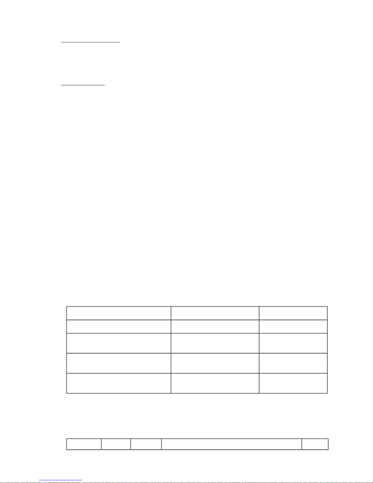
For each supervision value, a two-bit field exists. The enumeration of this value (..L+..H*2) is:
WIENER LV devices
0 ignore the failure
1 switch off this channel
2 switch off all channels with the same group number
3 switch off the complete crate.
iseg HV devices
0 ignore the failure
1 switch off this channel by ramp down the voltage
2 switch off this channel by set a internal EmergencyOff
3 switch off the whole board of the HV module by set EmergencyOff.
The position of the bit fields in the integer value are:
Bit 0, 1: outputFailureMinSenseVoltage
Bit 2, 3: outputFailureMaxSenseVoltage
Bit 4, 5: outputFailureMaxTerminalVoltage
Bit 6, 7: outputFailureMaxCurrent
Bit 8, 9: outputFailureMaxTemperature
Bit 10,11: outputFailureMaxPower
Bit 12, 13: outputFailureInhibit
Bit 14, 15: outputFailureTimeout
The iseg HV devices can use the bit fields:
outputFailureMaxCurrent support of the function delayed trip
The programmed activity will start when the actual current exceeded permanently the value of
the item outputCurrent over the span of the programmed time out (set via the
itemoutputTripTimeMaxCurrent).
outputFailureInhibit support of the optional hardware function
EXTERNAL INHIBIT per channel
The programmed activity will start when an external channel inhibit occurs
The channel state have to be in disableKill for a proper work of the configuration of the behaviour for the
functions above.
Settings for outputSupervisionBehavior:
Action outputFailureMaxCurrent outputFailureInhibit
ignore the failure 0 0
switch off this channel by ramp down the
voltage
64 4096
switch off this channel by set a internal
EmergencyOff
128 8192
switch off the whole board of the HV
module by set EmergencyOff
192 12288
Attention!!! In order to use delayed software trips please make sure to have a firmware on the ISEG high
voltage modules which supports this feature. Please see the following table of supported firmware releases.
In case of older firmware the software trip will not act, i.e. the error will be detected but no action (ram
down of channel) will happen.
Name of Release Date Description Device
30. May 2018 38
Page 40
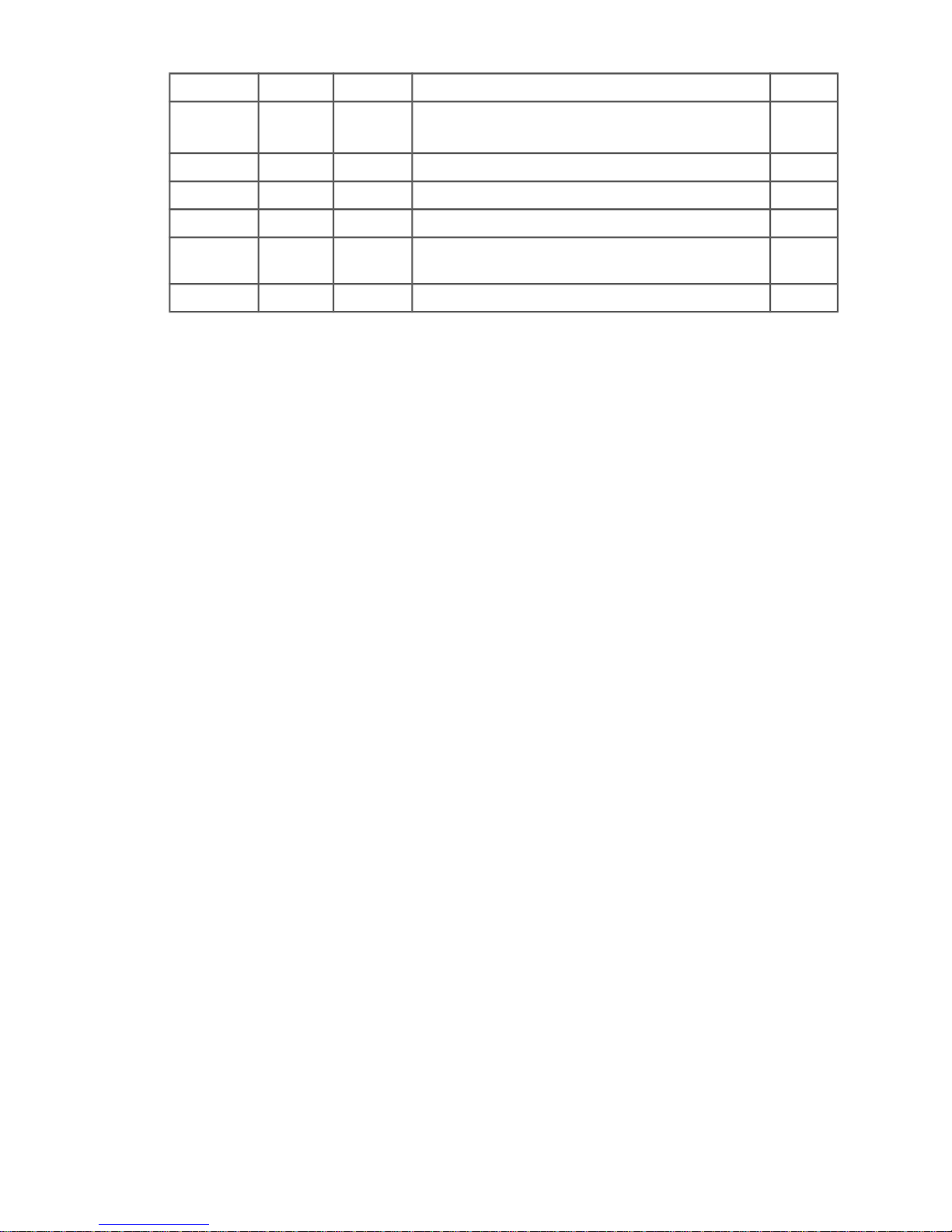
firmware or higher class
E16D0 4.25 05/08/09 EDS 16/32 channel distributor module, with Vmax
from V
O max
to (V
O max
- 1kV)
1
E16D1 4.25 05/08/09 EDS 16/32 distributor module 21
E08C0 2.22 02/23/09 EHS 4/8/16 channel, common GND module 24
E08F0 2.27 12/18/08 EHS 4/8/16 channel, floating GND module 25
E08F2 4.06 06/23/09 EHS 4/8/16 channel, floating GND module, 2 ranges
for measurement of current
26
E08B0 1.02 07/10/09 EBS 8/16 bipolar channels, distributor module 28
Example of necessary SNMP commands for the delayed trip function:
snmpset -Oqv -v 2c -m +WIENER-CRATE-MIB -c guru 192.168.2.25 groupsSwitch.64 i 4
disableKill
snmpset -Oqv -v 2c -m +WIENER-CRATE-MIB -c guru 192.168.2.25 outputVoltage.u100 F 60
60.000000 V
snmpset -Oqv -v 2c -m +WIENER-CRATE-MIB -c guru 192.168.2.25 outputSwitch.u100 i 1
On
snmpget -Oqv -v 2c -m +WIENER-CRATE-MIB -c public 192.168.2.25 outputVoltage.u100
60.000000 V
snmpget -Oqv -v 2c -m +WIENER-CRATE-MIB -c public 192.168.2.25
outputMeasurementSenseVoltage.u100
60.104588 V
snmpget -Oqv -v 2c -m +WIENER-CRATE-MIB -c public 192.168.2.25
outputMeasurementCurrent.u100
0.000001 A
snmpgetx -Oqv -v 2c -m +WIENER-CRATE-MIB -c public 192.168.2.25
outputMeasurementCurrent.u100
0.000000735 A
snmpget -Oqv -v 2c -m +WIENER-CRATE-MIB -c public 192.168.2.25
outputSupervisionBehavior.u100
0
snmpset -Oqv -v 2c -m +WIENER-CRATE-MIB -c guru 192.168.2.25 outputSupervisionBehavior.u100
i 64
64
snmpget -Oqv -v 2c -m +WIENER-CRATE-MIB -c public 192.168.2.25
outputSupervisionBehavior.u100
64
snmpget -Oqv -v 2c -m +WIENER-CRATE-MIB -c public 192.168.2.25
outputTripTimeMaxCurrent.u100
0 ms
snmpset -Oqv -v 2c -m +WIENER-CRATE-MIB -c guru 192.168.2.25
outputTripTimeMaxCurrent.u100 i 3000
3000 ms /* delay of 3 sconds */
snmpget -Oqv -v 2c -m +WIENER-CRATE-MIB -c public 192.168.2.25 outputStatus.u100
"80 " /* outputOn */
snmpgetx -Oqv -v 2c -m +WIENER-CRATE-MIB -c public 192.168.2.25
outputMeasurementCurrent.u100
0.000000735 A
snmpsetx -Oqv -v 2c -m +WIENER-CRATE-MIB -c guru 192.168.2.25 outputCurrent.u100 F
0.0000007
0.000000700 A
snmpget -Oqv -v 2c -m +WIENER-CRATE-MIB -c public 192.168.2.25 outputStatus.u100
"04 08 " /*outputFailureMaxCurrent, outputRampDown */
snmpget -Oqv -v 2c -m +WIENER-CRATE-MIB -c public 192.168.2.25 outputStatus.u100
30. May 2018 39
Page 41

"04 " /* outputFailureMaxCurrent */
snmpset -Oqv -v 2c -m +WIENER-CRATE-MIB -c guru 192.168.2.25 outputSwitch.u100 i 10
clearEvents
snmpsetx -Oqv -v 2c -m +WIENER-CRATE-MIB -c guru 192.168.2.25 outputCurrent.u100 F 0.00001
0.000010000 A
snmpset -Oqv -v 2c -m +WIENER-CRATE-MIB -c guru 192.168.2.25 outputSwitch.u100 i 1
On
snmpget -Oqv -v 2c -m +WIENER-CRATE-MIB -c public 192.168.2.25 outputStatus.u100
"80 10 " /* outputOn, outputRampUp */
/* a load has been switched on channel 0 to bring them in state CC current limited */
snmpget -Oqv -v 2c -m +WIENER-CRATE-MIB -c public 192.168.2.25 outputStatus.u100
"80 20 " /* outputOn, outputCurrentLimited */
.
snmpget -Oqv -v 2c -m +WIENER-CRATE-MIB -c public 192.168.2.25 outputStatus.u100
"80 20 " /* outputOn, outputCurrentLimited */
/* the delayed trip fuction ramps the voltage after 3 seconds to zero */
snmpget -Oqv -v 2c -m +WIENER-CRATE-MIB -c public 192.168.2.25 outputStatus.u100
"04 08 " /* outputFailureMaxCurrent, outputRampDown */
7.5 ISEG Load unit module commands
Item Type Access Unit
outputMeasurementTerminalVoltage float read [V]
outputMeasurementCurrent float read [A]
DESCRIPTION
The items outputMeasurementTerminalVoltage and outputMeasurementCurrent return the voltage
and current measured internally by the the load unit. These values are only measured if the external
measurement and ripple measurement are turned off.
Item Type Access Switch functions
outputSwitch integer read-write clearEvents (10)
setExternalAndRippleMeasurementOff (20)
setExternalMeasurementOn (21)
setRippleMeasurementOn (22)
setExternalAndRippleMeasurementOn (23)
DESCRIPTION
The item outputSwitch allows to activate or deactivate external measurements for a channel via the
measurement outputs on the front panel of the load unit.
The value setExternalMeasurementOn activates the voltage and current measurement outputs for the
channel.
The value setRippleMeasurementOn activates the ripple measurement output for the channel.
The value setExternalAndRippleMeasurementOn activates all three measurement outputs for the
channel.
The value setExternalAndRippleMeasurementOn deactivates all measurement outputs for the channel.
Note the measurement output can only be activated for one channel at the same time, i.e. if an output
is activated for another channel the previously switched channel is deactivated.
If an external measurement output is activated no internal measurement will be executed. In order to
reactivate the internal measurement, the external measurement must be completely deactivated. (If the
current output status is unknown this can be done by writing setExternalAndRippleMeasurementOn and
then setExternalAndRippleMeasurementOff for an arbitrary channel.)
30. May 2018 40
Page 42

All other SNMP items from the branch outputTable are readable for the SNMP compatibility but will not
be used by the load unit.
7.6 ISEG Module commands
Item Type Access
moduleDescription octet string read
Reply:
Company name, firmware name, channel number, serial number
for instance iseg, E24D1, 24, 713100, 5.03
Item Type Access
moduleAuxiliaryMeasurementVoltage0 float read
Returns the measurement value of the line supply 24 Volt.
moduleAuxiliaryMeasurementVoltage1 float read
Returns the measurement value of the line supply 5 Volt.
7.7 WIENER MPV Module commands
outputUserConfig OBJECT-TYPE
-- FROM WIENER-CRATE-MIB
SYNTAX Integer32 (0..127)
MAX-ACCESS read-write
STATUS current
DESCRIPTION "Definition of user-changeable items.
A bit field packed into an integer which define the behavior of the output channel.
Usable for WIENER LV devices only.
The position of the bit fields in the integer value are:
Bit 0: Voltage ramping at switch off:
0: Ramp down at switch off.
1: No ramp at switch off (immediate off)
Bit 1, 2: Set different regulation modes, dependent on the
cable inductance:
0: fast: short cables, up to 1 meter.
1: moderate: cables from 1 to 30 meter.
2: fast: identical to 0 (should not be used)
3: slow: cables longer than 30 meter.
Bit 3: Internal sense line connection to the output (MPOD only):
0: The sense input at the sense connector is used
30. May 2018 41
Page 43

for regulation.
1: The output voltage is used for regulation.
Any signals at the sense connector are ignored.
Bit 4: Enable External Inhibit input.
0: The external inhibit input is ignored.
1: The external inhibit input must be connected to
a voltage source to allow switch on.
Bit 5: Disable Global Inhibit inputs.
0: The global inhibit/interlock inputs of the system is active.
1: The global inhibit/interlock inputs of the system is ignored.
Bit 6: Automatic Power On.
0: After switching the main system switch ON, the output is not
switched on automatically. A separate outputSwitch command is
required.
1: After switching the main system switch ON, the output is
switched on automatically. If 'Disable Global Inhibit' (bit 5)
is set, the output will be switched on regardless of the global
inhibit/interlock signals.
outputSupervisionBehavior OBJECT-TYPE
-- FROM WIENER-CRATE-MIB
SYNTAX Integer32 (0..65535)
MAX-ACCESS read-write
STATUS current
DESCRIPTION "A bit field packed into an integer which define the behavior of the output channel /
power supply after failures.
For each supervision value, a two-bit field exists.
The enumeration of this value (..L+..H*2) is:
WIENER LV devices
0 ignore the failure
1 switch off this channel
2 switch off all channels with the same group number
3 switch off the complete crate.
iseg HV devices
0 ignore the failure
1 switch off this channel by ramp down the voltage
2 switch off this channel by a emergencyOff
3 switch off the whole board of the HV module by emergencyOff.
The position of the bit fields in the integer value are:
Bit 0, 1: outputFailureMinSenseVoltage
Bit 2, 3: outputFailureMaxSenseVoltage
30. May 2018 42
Page 44

Bit 4, 5: outputFailureMaxTerminalVoltage
Bit 6, 7: outputFailureMaxCurrent
Bit 8, 9: outputFailureMaxTemperature
Bit 10, 11: outputFailureMaxPower
Bit 12, 13: outputFailureInhibit
Bit 14, 15: outputFailureTimeout "
7.8 Change of community names / setting of passwords
For the communication with MPOD modules 4 types of SNMP communities are used, “public",
"private", "admin"and "guru". By default the community names are equal to the community
types.
snmpwalk -v 2c -m +WIENER-CRATE-MIB -c guru 192.168.0.80
snmpCommunityName
WIENER-CRATE-MIB::snmpCommunityName.public = STRING: "public"
WIENER-CRATE-MIB::snmpCommunityName.private = STRING: "private"
WIENER-CRATE-MIB::snmpCommunityName.admin = STRING: "admin"
WIENER-CRATE-MIB::snmpCommunityName.guru = STRING: "guru"
snmpwalk -v 2c -m +WIENER-CRATE-MIB -c private 192.168.0.80 snmpCommunityName
WIENER-CRATE-MIB::snmpCommunityName.public = STRING: "public"
WIENER-CRATE-MIB::snmpCommunityName.private = STRING: "private"
In order to secure the MPOD system communication the community names can be used as
passwords and be changed accordingly. The following example shows how the change and test
the community names. Using a wrong community name will result in a time out error. Please
note, that especially the communities with write access (private, admin, guru) should be protected.
snmpset -v 2c -m +WIENER-CRATE-MIB -c guru 192.168.0.80
snmpCommunityName.guru s seCrET
WIENER-CRATE-MIB::snmpCommunityName.guru = STRING: "seCrET"
snmpwalk -v 2c -m +WIENER-CRATE-MIB -c guru 192.168.0.80
snmpCommunityName
Timeout: No Response from 192.168.0.80
snmpwalk -v 2c -m +WIENER-CRATE-MIB -c seCrET 192.168.0.80 snmpCommunityName
WIENER-CRATE-MIB::snmpCommunityName.public = STRING: "public"
WIENER-CRATE-MIB::snmpCommunityName.private = STRING: "private"
WIENER-CRATE-MIB::snmpCommunityName.admin = STRING: "admin"
WIENER-CRATE-MIB::snmpCommunityName.guru = STRING: "seCrET"
7.9 MIB Browser
There are several commercial or open source MIB-Browser programs available which can be used
for SNMP communication. These provide often a simple GUI and allow SNMP calls. Following
is a list of some free or open source MIB – browsers:
http://www.ireasoning.com/mibbrowser.shtml
http://www.serverscheck.com/mib_browser/
http://www.mibble.org/
30. May 2018 43
Page 45
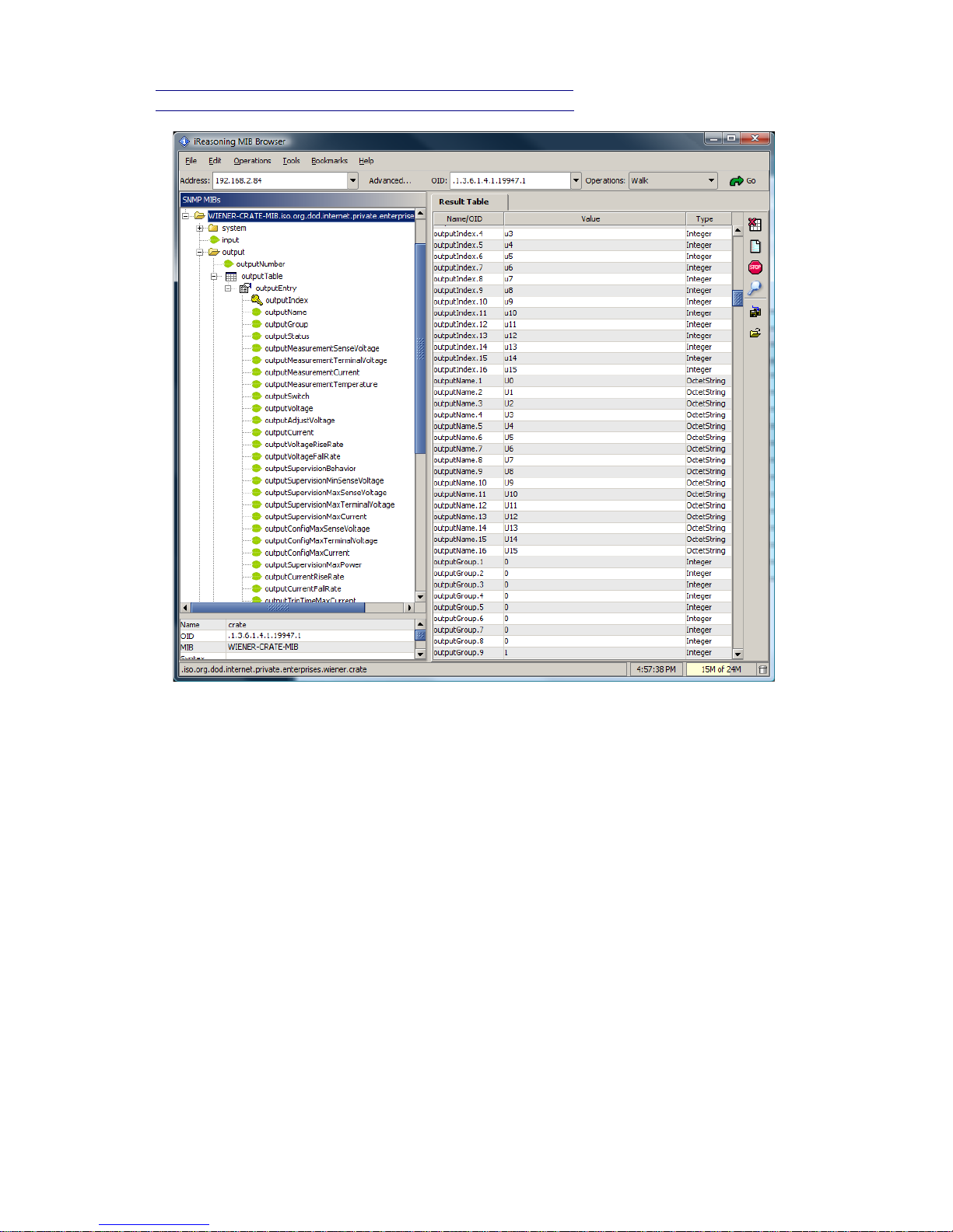
http://www.ks-soft.net/hostmon.eng/mibbrowser/index.htm
http://www.tembria.com/products/snmpbrowser/index.html
7.10 A BASH Simple Script for SNMP
All of the commands above could be combined into scripts to set and monitor a predefined set of
channels. For example a Bash script to read all channels and set the voltages and current limit to
the same value for each channel could look like:
#!/bin/bash
# Simple Bash Script that will read and set all channels in a MPOD crate
ip=192.168.2.25
path=/usr/share/snmp/mibs
setVoltage=5
setCurrent=.100
setStatus=1
setRamp=100
channelCount=$(snmpget -Oqv -v 2c -M $path -m +WIENER-CRATE-MIB -c guru $ip outputNumber.0)
indices=$(snmpwalk -Oqv -v 2c -M $path -m +WIENER-CRATE-MIB -c guru $ip outputIndex)
x=(`echo $indices | tr ' ' ' '`)
COUNTER=0
30. May 2018 44
Page 46

while [ $COUNTER -lt $channelCount ]; do
index=$(echo ${x[${COUNTER}]})
voltage=$(snmpset -OqvU -v 2c -M $path -m +WIENER-CRATE-MIB -c guru $ip outputVoltage.$index F
$setVoltage)
iLimit=$(snmpset -OqvU -v 2c -M $path -m +WIENER-CRATE-MIB -c guru $ip outputCurrent.$index F
$setCurrent)
rampspeed=$(snmpset -OqvU -v 2c -M $path -m +WIENER-CRATE-MIB -c guru $ip outputVoltageRiseRate.
$index F $setRamp)
status=$(snmpset -OqvU -v 2c -M $path -m +WIENER-CRATE-MIB -c guru $ip outputSwitch.$index i
$setStatus)
voltage=$(snmpget -OqvU -v 2c -M $path -m +WIENER-CRATE-MIB -c guru $ip outputVoltage.$index)
iLimit=$(snmpget -OqvU -v 2c -M $path -m +WIENER-CRATE-MIB -c guru $ip outputCurrent.$index)
sense=$(snmpget -OqvU -v 2c -M $path -m +WIENER-CRATE-MIB -c guru $ip
outputMeasurementSenseVoltage.$index)
current=$(snmpget -OqvU -v 2c -M $path -m +WIENER-CRATE-MIB -c guru $ip
outputMeasurementCurrent.$index)
rampspeed=$(snmpget -OqvU -v 2c -M $path -m +WIENER-CRATE-MIB -c guru $ip outputVoltageRiseRate.
$index)
status=$(snmpget -OqvU -v 2c -M $path -m +WIENER-CRATE-MIB -c guru $ip outputSwitch.$index)
echo "$voltage $iLimit $sense $current $rampspeed $status"
let COUNTER=COUNTER+1
done
30. May 2018 45
Page 47

7.11 MPOD SNMP Parameter List (most common)
Parameter Multi Access Type
sysMainSwitch 1 R/W i
sysStatus 1 R/W i
sysVmeSysReset 1 R/W i
outputNumber 1 R i
groupsNumber 1 R i
outputName 320 R string
outputGroup 320 R i
outputStatus 320 R i
outputMeasurementSenseVoltage 320 R F
outputMeasurementTerminalVoltage 320 R F
outputMeasurementCurrent 320 R F
outputMeasurementTemperature 320 R i
outputSwitch 320 R/W i
outputVoltage 320 R/W F
outputCurrent 320 R/W F
outputVoltageRiseRate 320 R/W F
outputVoltageFallRate 320 R/W F
outputSupervisionBehavior 320 R/W i
outputSupervisionMinSenseVoltage 320 R/W F
outputSupervisionMaxSenseVoltage 320 R/W F
outputSupervisionMaxTerminalVoltage 320 R/W F
outputSupervisionMaxCurrent 320 R/W F
outputSupervisionMaxTemperature 320 R/W i
outputConfigMaxSenseVoltage 320 R F
outputConfigMaxTerminalVoltage 320 R F
outputConfigMaxCurrent 320 R F
outputConfigMaxPower 320 R F
sensorNumber 1 R i
sensorTemperature 12 R i
sensorWarningThreshold 12 R/W i
sensorFailureThreshold 12 R/W i
snmpCommunityName 4 R/W string
psFirmwareVersion 1 R string
psSerialNumber 1 R string
psOperatingTime 1 R i
psDirectAccess 1 R/W string
fanFirmwareVersion 1 R string
fanSerialNumber 1 R string
fanOperatingTime 1 R i
fanAirTemperature 1 R i
fanSwicthOffDelay 1 R/W i
fanNominalSpeed 1 R/W i
fanNumberOfFans 1 R i
fanSpeed 6 R i
(see SNMP tree structure at end of manual for full structure)
30. May 2018 46
Page 48
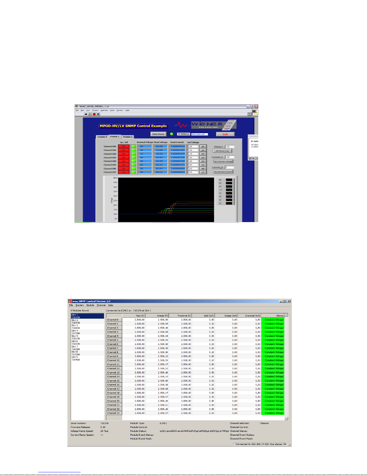
7.12 LabView Control Program (NETSNMP)
All LabView MPOD function VI’s are using SNMP calls from the
WIENER_SNMP_LV.DLL. This DLL requires the installation of NETSNMP and the
WIENER –CRATE-MIB.txt file as described in Chapter 6.3!
The supplied LabView programs allow controlling both low and high voltage channels for
small configurations of up to 10 MPOD modules. The program is provided as executable
which will require the NI LV Run-time-engine. All source code is available on the CD-ROM.
Please run these VI's with either LabView 8.5 or higher .
Example for LabView VI for 8 channel high voltage module
7.13 ISEG SNMP Control Program (NETSNMP)
The supplied iseg SNMP Control program allow controlling high voltage channels for
configurations of up to 10 HV or LV modules plugged into the MPOD crate. The programs are
provided as executable. All source code is available on the CD-ROM.
30. May 2018 47
Page 49

7.14 C++ programming (NetSNMP)
Using NetSNMP C++ programs can be easily written for monitoring and control of MPOD
low / high voltage modules. For Windows all needed functions are provided by a
dynamically loadable library WIENER_SNMP.DLL. This DLL requires NETSNMP and the
WIENER –CRATE-MIB.txt file as described in chapter 6.3!
The following functions are provided in this library (for details see source code):
SnmpInit
SnmpCleanup
SnmpOpen
SnmpClose
getMainSwitch
setMainSwitch
getMainStatus
getVmeReset
setVmeReset
getOutputNumber
getOutputGroups
getOutputGroup
getChannelStatus
getOutputSenseMeasurement
getOutputTerminalMeasurement
getCurrentMeasurement
getTemperatureMeasurement
setChannelSwitch
getChannelSwitch
getOutputVoltage
setOutputVoltage
getOutputCurrent
setOutputCurrent
getOutputRiseRate
setOutputRiseRate
getOutputFallRate
setOutputFallRate
getOutputSupervisionBehavior
setOutputSupervisionBehavior
getOutputSupervisionMinSenseVoltage
setOutputSupervisionMinSenseVoltage
getOutputSupervisionMaxSenseVoltage
setOutputSupervisionMaxSenseVoltage
getOutputSupervisionMaxTerminalVoltage
setOutputSupervisionMaxTerminalVoltage
getOutputSupervisionMaxCurrent
setOutputSupervisionMaxCurrent
getOutputSupervisionMaxTemperature
getOutputConfigMaxSenseVoltage
getOutputConfigMaxTerminalVoltage
getOutputConfigMaxCurrent
getOutputConfigMaxPower
30. May 2018 48
Page 50

getSensorNumber
getSensorTemp
getSensorWarningTemperature
setSensorWarningTemperature
getSensorFailureTemperature
setSensorFailureTemperature
getPsOperatingTime
getFanOperatingTime
getFanAirTemperature
getFanSwitchOffDelay
setFanSwitchOffDelay
getFanNominalSpeed
setFanNominalSpeed
setFanNominalSpeed
getFanNumberOfFans
getFanSpeed
snmpSetDouble
snmpGetDouble
snmpSetInt
snmpGetInt
30. May 2018 49
Page 51

8 MPOD Crate
Powered chassis for multichannel low and high voltage modules
Construction 8 Ux 19” crate max.10 modules, up to3 kW or 6KW
output power /
3,6kW or 2x 3,6KW input power
Slots: 10 + ½ (MPOD controller)
Dimensions (w, h, d) 483 mm x 460 mm x 355 mm
Weight: 31,5 kg
9 Primary Power Supply
The power supply provides all necessary supply voltages for the LV- and HV-Modules.
It is connected to the mains (World wide input 100..240V AC, 50..60 Hz).
● World wide input: 100..240V AC, 50..60 Hz, single phase
● Sinusoidal current input, up to 16A or 2x 16A, depending on the used modules
9.1 Power Box Data Sheet
3U box with max. 6 power modules.
Mains Input
Rated Input Voltage: 106 – 230 V AC, +/- 15% variation allowed
Rated Input Current: 16 A or (2x 16A)
Sinusoidal: CE CE EN 60555, IEC 555 pow. fact. 0,98 (230VAC)
Inrush current: 16 A, cold unit
Input protection: An external fuse or circuit breaker has to be installed
(16A max.)
RF rejection: EN 55 022 Class B, Input and Output
Output protection
overload: current limiting for booster circuits, 90°C cut off
temperature
Dimensions: 4U x 14 PU width acc. to IEC 60297, 450 mm deep
Weight: 4,7 kg
Operation temperature: 0....45°C without derating, storage: -30°C … + 85°C
M T B F electronics: 40°C ambient: ca. 100 000 h
integrated fan: 40°C ambient: ca. 65 000 h, 25° ambient >85000h
30. May 2018 50
Page 52

10 MPOD Low Voltage module MPV 8xx , MPV 4xx data sheet
• 8 channel low voltage module with floating outputs with individual return lines and sense lines
• Polarity configurable, outputs are insulated from each other and the chassis mainframe earth with
125V DC working voltage (Test voltage = 500VDC)
• 0.2% / 10K output voltage stability
• Voltage set / monitor: 15 bit resolution, +/-0.1% of full scale or better accuracy, measurement of
both sense and terminal voltage
• Current limit set / monitor: 15 bit resolution, +/-0.5% of full scale or better accuracy
• Ramp-up / down programmable from 1 V/s to 500 V/s in 1 V/s steps.
• Output Voltage Ripple: < 10mV
pp
; 1mV
Rms
with 350MHz Bandwidth
< 5mVpp; 0.5mV
Rms
with 100MHz Bandwidth
< 3mVpp; 0.5mV
Rms
with 20MHz Bandwidth
• Low conducted disturbance current (Funkstörstrom TÜV)
• Static Regulation: < 10mV
• Dynamic Regulation: <100mV with I = +/- 25% change and 70A/s
recovery time < 5mS
• Dimensions: 6U x 40.64mm x 220mm
• Front Panel Indicators: tri-color LED's with on / off / failure for every channel
• Output Channels Connectors:
2x 37-pin D-sub (outputs, returns, sense lines, chassis and interlock loop pair)
• Interlock Loop – optional
• Safety Loop – in connector PIN 18 and 37
Type Channels Voltage I Max Peak PowerV-Res I-Res Ripple
MPV 8008I 8 0 to 8V 10A 50W / ch. 0.5mV 0.5mA <3mVpp
MPV 4008I 4 0 to 8V 20A 100W / ch. 0.5mV 0.5mA <3mVpp
MPV 8016I 8 0 to 16V 5A 50W / ch. 1mV 0.25mA <2mVpp
MPV 4016I 4 0 to 16V 10A 100W / ch. 1mV 0.25mA <2mVpp
MPV 8030I 8 0 to 30V 2.5A 50W / ch. 2mV 0.12mA <2mVpp
MPV 4030I 4 0 to 30V 5A 100W / ch. 2mV 0.12mA <2mVpp
MPV 8060I 8 0 to 60V 1A 50W / ch. 4mV 0.06mA <2mVpp
MPV 4060I 4 0 to 60V 2A 100W / ch. 4mV 0.06mA <2mVpp
MPV 8120I 8 0 to 120V 100mA 50W / ch. 4mV 4 µA <2mVpp
30. May 2018 51
Page 53

Regulation fast remote sense circuit (short sensed distance, sense connected to
output at the MPOD module):
Static: MVP 2-8 V < 15 mV (+/-100% load, +/- full
mains range)
MVP other voltages < 0.05 % (+/-100% load, +/- full DC
input range)
Dynamic (0.5 m
wire):
MVP 2-8 V < 100 mV (50 % - 75 % load
change)
other < 0.7 % (50 % - 75 % load
change)
Recovery Time: MVP 2-8V 1%: 0.2 ms
0.1%: 0.5
ms
(50 % - 75 % load
change)
MVP 5-16V, 7-24V 1%: 0.0 ms
0.1%: 1.0
ms
(50 % - 75 % load
change)
MVP 30-60V 1%: 0.5 ms
0.1%: 1.0
ms
(50 % - 75 % load
change)
Conditions Current slope <1000A/ms, 200uF per 1A parallel to load, fast
regulation mode selected.
Regulation slow remote sense circuit (long sensed distance):
Static: MVP 2-8V/ 30-60V < 15 mV (+/-100% load, +/- full
mains range)
Other < 0.05 % (+/-100% load, +/- full
mains range)
Dynamic: Dynamic deviation depends on current slope resp. filter
capacitors at load side only
30m cable to load, 0,3mF capacitance at load side, 1V drop at
nominal load, 10% - 90 % load change with 3ms slope (50A
output= 13,33A/ms) leads to less than 10% temporary output
voltage deviation
Recovery Time (40m
wire, 5V at load side,
U
drop
< 2 V:
MVP 2-7V, 2-8V 10%: <15
ms
1%: <25 ms
(50 % - 75 % load
change)
Other 10%: <15
ms
1%: < 33 ms
(50 % - 75 % load
change)
30. May 2018 52
Page 54

11 SNMP examples for MPOD and high voltage EHS/EDS module
/*****************************************************************************************************/
/* */
/* SNMP example for control of iseg Multi-Channel High Voltage Power Supply Modules in */
/* a W-IE-NE-R MPOD crate */
/* */
/* snmpget -Oqv -v 2c -M $path -m +WIENER-CRATE-MIB -c public 192.168.16.222 outputVoltage.u100 */
/* This command will request the value from datapoint set voltage. */
/* snmpget: starts a SNMP request */
/* -v 2c: This parameters specifies which version of the SNMP to use. WIENER devices use SNMP 2C. */
/* -M $path: This parameter should be replaced with the path to the WIENERCRATE-MIB.txt file. */
/* It is not needed in case the default path is used. */
/* -m +WIENER-CRATE-MIB: This parameter tells the command to look at the WIENER-CRATE-MIB */
/* to resolve the OID name. */
/* -c public: This specifies which community of values can be accessed */
/* 192.168.16.222: The IP address of the MPOD crate. */
/* outputVoltage.u100: The SNMP item to the data point set voltage of a module in the second */
/* slot of the MPOD crate HV channel 0. */
/* */
/* snmpset -Oqv -v 2c -m +WIENER-CRATE-MIB -c public 192.168.16.222 outputVoltage.u100 F 60 */
/* This command writes a floating point value to the datapoint set voltage. */
/* snmpset: starts a SNMP write instruction */
/* -c guru: This specifies the community for write accesses */
/* F 60: The F specifies the write value as a floating point formated value. */
/* The 60 is the write value 60 Volt. */
/* */
/* snmpset -Oqv -v 2c -m +WIENER-CRATE-MIB -c guru 192.168.16.222 outputSwitch.u100 i 1 */
/* This command write a switch on of the HV for one channel. */
/* outputSwitch.u100 i 1: Write of an integer formatted value to the item outputSwitch. */
/* With that item it is possible to switch differnt functions for instance */
/* set On(1). */
/*****************************************************************************************************/
snmpget -Oqv -v 2c -m +WIENER-CRATE-MIB -c public 192.168.16.222 outputVoltage.u100
200.000000 V
snmpset -Oqv -v 2c -m +WIENER-CRATE-MIB -c guru 192.168.16.222 outputVoltage.u100 F 60
60.000000 V
snmpset -Oqv -v 2c -m +WIENER-CRATE-MIB -c guru 192.168.16.222 outputSwitch.u100 i 1
On
snmpget -Oqv -v 2c -m +WIENER-CRATE-MIB -c public 192.168.16.222 outputVoltage.u100
60.000000 V
snmpget -Oqv -v 2c -m +WIENER-CRATE-MIB -c public 192.168.16.222 outputMeasurementSenseVoltage.u100
60.104588 V
snmpget -Oqv -v 2c -m +WIENER-CRATE-MIB -c public 192.168.16.222 outputMeasurementSenseVoltage.u100
60.104713 V
snmpget -Oqv -v 2c -m +WIENER-CRATE-MIB -c public 192.168.16.222 outputMeasurementCurrent.u100
0.000001 A
snmpgetx -Oqv -v 2c -m +WIENER-CRATE-MIB -c public 192.168.16.222 outputMeasurementCurrent.u100
0.000000735 A
snmpget -Oqv -v 2c -m +WIENER-CRATE-MIB -c public 192.168.16.222 outputSupervisionBehavior.u100
0
snmpset -Oqv -v 2c -m +WIENER-CRATE-MIB -c guru 192.168.16.222 outputSupervisionBehavior.u100 i 64
64
snmpget -Oqv -v 2c -m +WIENER-CRATE-MIB -c public 192.168.16.222 outputSupervisionBehavior.u100
30. May 2018 53
Page 55

64
snmpget -Oqv -v 2c -m +WIENER-CRATE-MIB -c public 192.168.16.222 outputTripTimeMaxCurrent.u100
0 ms
snmpset -Oqv -v 2c -m +WIENER-CRATE-MIB -c guru 192.168.16.222 outputTripTimeMaxCurrent.u100 i 3000
3000 ms /* delay of 3 sconds */
snmpget -Oqv -v 2c -m +WIENER-CRATE-MIB -c public 192.168.16.222 outputStatus.u100
"80 " /* outputOn */
snmpgetx -Oqv -v 2c -m +WIENER-CRATE-MIB -c public 192.168.16.222 outputMeasurementCurrent.u100
0.000000735 A
snmpsetx -Oqv -v 2c -m +WIENER-CRATE-MIB -c guru 192.168.16.222 outputCurrent.u100 F 0.0000007
0.000000700 A
snmpget -Oqv -v 2c -m +WIENER-CRATE-MIB -c public 192.168.16.222 outputStatus.u100
"04 08 " /*outputFailureMaxCurrent, outputRampDown */
snmpget -Oqv -v 2c -m +WIENER-CRATE-MIB -c public 192.168.16.222 outputStatus.u100
"04 " /* outputFailureMaxCurrent */
snmpset -Oqv -v 2c -m +WIENER-CRATE-MIB -c guru 192.168.16.222 outputSwitch.u100 i 10
clearEvents
snmpsetx -Oqv -v 2c -m +WIENER-CRATE-MIB -c guru 192.168.16.222 outputCurrent.u100 F 0.00001
0.000010000 A
snmpset -Oqv -v 2c -m +WIENER-CRATE-MIB -c guru 192.168.16.222 outputSwitch.u100 i 1
On
snmpget -Oqv -v 2c -m +WIENER-CRATE-MIB -c public 192.168.16.222 outputStatus.u100
"80 10 " /* outputOn, outputRampUp */
/* a load has been switched on channel 0 to bring them in state CC current limited */
snmpget -Oqv -v 2c -m +WIENER-CRATE-MIB -c public 192.168.16.222 outputStatus.u100
"80 20 " /* outputOn, outputCurrentLimited */
snmpget -Oqv -v 2c -m +WIENER-CRATE-MIB -c public 192.168.16.222 outputStatus.u100
"80 20 " /* outputOn, outputCurrentLimited */
snmpget -Oqv -v 2c -m +WIENER-CRATE-MIB -c public 192.168.16.222 outputStatus.u100
"80 20 " /* outputOn, outputCurrentLimited */
snmpget -Oqv -v 2c -m +WIENER-CRATE-MIB -c public 192.168.16.222 outputStatus.u100
"80 20 " /* outputOn, outputCurrentLimited */
snmpget -Oqv -v 2c -m +WIENER-CRATE-MIB -c public 192.168.16.222 outputStatus.u100
"80 20 " /* outputOn, outputCurrentLimited */
/* the delayed trip fuction pamps the voltage after 3 seconds to zero */
snmpget -Oqv -v 2c -m +WIENER-CRATE-MIB -c public 192.168.16.222 outputStatus.u100
"04 08 " /* outputFailureMaxCurrent, outputRampDown */
snmpget -Oqv -v 2c -m +WIENER-CRATE-MIB -c public 192.168.16.222 outputStatus.u100
"04 08 " /* outputFailureMaxCurrent, outputRampDown */
30. May 2018 54
Page 56

12 WIENER SNMP Parameter structure
// GENERATED WITH
// snmptranslate -w 120 -Tp WIENER-CRATE-MIB::crate > SnmpTree.txt
//
+--crate(1)
+--system(1)
| +-- -RW- EnumVal sysMainSwitch(1)
| | Values: off(0), on(1)
| +-- -R-- BitString sysStatus(2)
| | Values: mainOn(0), mainInhibit(1), localControlOnly(2), inputFailure(3), outputFailure(4),
| | fantrayFailure(5), sensorFailure(6), vmeSysfail(7), plugAndPlayIncompatible(8), busReset(9),
| | supplyDerating(10), supplyFailure(11), supplyDerating2(12), supplyFailure2(13)
| +-- -RW- EnumVal sysVmeSysReset(3)
| | Values: trigger(1)
| +-- -RW- INTEGER sysHardwareReset(4)
| +-- -RW- EnumVal sysFactoryDefaults(5)
| | Values: off(0), on(1)
| +-- -RW- BitString sysConfigDoMeasurementCurrent(10)
| | Values: ch0(0), ch1(1), ch2(2), ch3(3), ch4(4), ch5(5), ch6(6), ch7(7)
| +-- -RW- Integer32 sysOperatingTime(11)
| +-- -RW- Integer32 sysDebugMemory8(1024)
| | Range: 0..255
| +-- -RW- Integer32 sysDebugMemory16(1025)
| | Range: 0..65535
| +-- -RW- Integer32 sysDebugMemory32(1026)
| | Range: -2147483648..2147483647
| +-- -RW- String sysDebug(1027)
| | Size: 520
| +-- -RW- String sysDebugDisplay(1028)
| +-- -RW- String sysDebugBoot(1029)
|
+--input(2)
+--output(3)
| +-- -R-- Integer32 outputNumber(1)
| | Range: 0..1999
| |
| +--outputTable(2)
| | |
| | +--outputEntry(1)
| | | Index: outputIndex
| | |
| | +-- ---- EnumVal outputIndex(1)
| | | Values: u0(1), u1(2), u2(3), u3(4), u4(5), u5(6), u6(7), u7(8), u8(9), u9(10), u10(11), u11(12),
| | +-- -R-- String outputName(2)
| | | Textual Convention: DisplayString
| | | Size: 1..4
| | +-- -RW- Integer32 outputGroup(3)
| | | Range: 1..63
| | +-- -R-- BitString outputStatus(4)
| | | Values: outputOn(0), outputInhibit(1), outputFailureMinSenseVoltage(2),
| | | outputFailureMaxSenseVoltage(3), outputFailureMaxTerminalVoltage(4),
| | | outputFailureMaxCurrent(5), outputFailureMaxTemperature(6), outputFailureMaxPower(7),
| | | outputFailureTimeout(9), outputCurrentLimited(10), outputRampUp(11), outputRampDown(12),
| | | outputEnableKill(13), outputEmergencyOff(14), outputAdjusting(15),
| | | outputConstantVoltage(16), outputLowCurrentRange(17), outputCurrentBoundsExceeded(18),
| | | outputFailureCurrentLimit(19)
| | +-- -R-- Opaque outputMeasurementSenseVoltage(5)
| | | Textual Convention: Float
| | | Size:
| | +-- -R-- Opaque outputMeasurementTerminalVoltage(6)
| | | Textual Convention: Float
| | | Size:
| | +-- -R-- Opaque outputMeasurementCurrent(7)
| | | Textual Convention: Float
30. May 2018 55
Page 57

| | | Size:
| | +-- -R-- EnumVal outputMeasurementTemperature(8)
| | | Values: ok(-128), failure(127)
| | +-- -RW- EnumVal outputSwitch(9)
| | | Values: off(0), on(1), resetEmergencyOff(2), setEmergencyOff(3), clearEvents(10),
| | | setVoltageRippleMeasurementOff(20), setVoltageMeasurementOn(21),
| | | setRippleMeasurementOn(22), setVoltageRippleMeasurementOn(23)
| | +-- -RW- Opaque outputVoltage(10)
| | | Textual Convention: Float
| | | Size:
| | +-- -RW- Integer32 outputAdjustVoltage(11)
| | | Range: -128..127
| | +-- -RW- Opaque outputCurrent(12)
| | | Textual Convention: Float
| | | Size:
| | +-- -RW- Opaque outputVoltageRiseRate(13)
| | | Textual Convention: Float
| | | Size:
| | +-- -RW- Opaque outputVoltageFallRate(14)
| | | Textual Convention: Float
| | | Size:
| | +-- -RW- Integer32 outputSupervisionBehavior(15)
| | | Range: 0..65535
| | +-- -RW- Opaque outputSupervisionMinSenseVoltage(16)
| | | Textual Convention: Float
| | | Size:
| | +-- -RW- Opaque outputSupervisionMaxSenseVoltage(17)
| | | Textual Convention: Float
| | | Size:
| | +-- -RW- Opaque outputSupervisionMaxTerminalVoltage(18)
| | | Textual Convention: Float
| | | Size:
| | +-- -RW- Opaque outputSupervisionMaxCurrent(19)
| | | Textual Convention: Float
| | | Size:
| | +-- -RW- Integer32 outputSupervisionMaxTemperature(20)
| | +-- -RW- Opaque outputConfigMaxSenseVoltage(21)
| | | Textual Convention: Float
| | | Size:
| | +-- -RW- Opaque outputConfigMaxTerminalVoltage(22)
| | | Textual Convention: Float
| | | Size:
| | +-- -RW- Opaque outputConfigMaxCurrent(23)
| | | Textual Convention: Float
| | | Size:
| | +-- -RW- Opaque outputSupervisionMaxPower(24)
| | | Textual Convention: Float
| | | Size:
| | +-- -RW- Opaque outputCurrentRiseRate(25)
| | | Textual Convention: Float
| | | Size:
| | +-- -RW- Opaque outputCurrentFallRate(26)
| | | Textual Convention: Float
| | | Size:
| | +-- -RW- INTEGER outputTripTimeMaxCurrent(27)
| | | Range: 0..4000
| | +-- -R-- Opaque outputHardwareLimitVoltage(28)
| | | Textual Convention: Float
| | | Size:
| | +-- -R-- Opaque outputHardwareLimitCurrent(29)
| | | Textual Convention: Float
| | | Size:
| | +-- -RW- Opaque outputConfigGainSenseVoltage(30)
| | | Textual Convention: Float
30. May 2018 56
Page 58

| | | Size:
| | +-- -RW- Opaque outputConfigOffsetSenseVoltage(31)
| | | Textual Convention: Float
| | | Size:
| | +-- -RW- Opaque outputConfigGainTerminalVoltage(32)
| | | Textual Convention: Float
| | | Size:
| | +-- -RW- Opaque outputConfigOffsetTerminalVoltage(33)
| | | Textual Convention: Float
| | | Size:
| | +-- -RW- Opaque outputConfigGainCurrent(34)
| | | Textual Convention: Float
| | | Size:
| | +-- -RW- Opaque outputConfigOffsetCurrent(35)
| | | Textual Convention: Float
| | | Size:
| | +-- -RW- Integer32 outputUserConfig(37)
| | | Range: 0..31
| | +-- -RW- EnumVal outputRegulationMode(38)
| | | Values: fast(0), moderate(1), slow(2)
| | +-- -RW- Integer32 outputConfigMaxTemperature(39)
| | +-- -RW- Opaque outputResistance(40)
| | | Textual Convention: Float
| | | Size:
| | +-- -RW- String outputConfigDataS(1024)
| | +-- -RW- String outputConfigDataU(1025)
| |
| +-- -R-- Integer32 groupsNumber(3)
| | Range: 1..1999
| |
| +--groupsTable(4)
| | |
| | +--groupsEntry(1)
| | | Index: groupsIndex
| | |
| | +-- ---- Integer32 groupsIndex(1)
| | | Range: 0..1999
| | +-- -RW- EnumVal groupsSwitch(9)
| | Values: undefined(-1), off(0), on(1), resetEmergencyOff(2), setEmergencyOff(3), disableKill(4),
| | enableKill(5), disableAdjust(6), enableAdjust(7), clearEvents(10)
| |
| +-- -R-- Integer32 moduleNumber(5)
| | Range: 1..10
| |
| +--moduleTable(6)
| |
| +--moduleEntry(1)
| | Index: moduleIndex
| |
| +-- ---- EnumVal moduleIndex(1)
| | Values: ma0(1), ma1(2), ma2(3), ma3(4), ma4(5), ma5(6), ma6(7), ma7(8), ma8(9), ma9(10)
| +-- -R-- String moduleDescription(2)
| | Size: 0..39
| +--moduleAuxiliaryMeasurementVoltage(3)
| | +-- -R-- Opaque moduleAuxiliaryMeasurementVoltage0(1)
| | | Textual Convention: Float
| | | Size:
| | +-- -R-- Opaque moduleAuxiliaryMeasurementVoltage1(2)
| | Textual Convention: Float
| | Size:
| |
| +-- -R-- Opaque moduleHardwareLimitVoltage(4)
| | Textual Convention: Float
| | Size:
30. May 2018 57
Page 59

| +-- -R-- Opaque moduleHardwareLimitCurrent(5)
| | Textual Convention: Float
| | Size:
| +-- -RW- Opaque moduleRampSpeedVoltage(6)
| | Textual Convention: Float
| | Size:
| +-- -RW- Opaque moduleRampSpeedCurrent(7)
| | Textual Convention: Float
| | Size:
| +-- -R-- BitString moduleStatus(8)
| | Values: moduleIsFineAdjustment(0), moduleIsLiveInsertion(2), moduleIsHighVoltageOn(3),
| | moduleNeedService(4), moduleHardwareLimitVoltageIsGood(5), moduleIsInputError(6),
| | moduleIsNoSumError(8), moduleIsNoRamp(9), moduleSafetyLoopIsGood(10),
| | moduleIsEventActive(11), moduleIsGood(12), moduleSupplyIsGood(13),
| | moduleTemperatureIsGood(14), moduleIsKillEnable(15)
| +-- -R-- BitString moduleEventStatus(9)
| | Values: moduleEventPowerFail(0), moduleEventLiveInsertion(2), moduleEventService(4),
| | moduleHardwareLimitVoltageNotGood(5), moduleEventInputError(6),
| | moduleEventSafetyLoopNotGood(10), moduleEventSupplyNotGood(13),
| | moduleEventTemperatureNotGood(14)
| +-- -R-- INTEGER moduleEventChannelStatus(10)
| +-- -RW- EnumVal moduleDoClear(11)
| | Values: nothing(0), doClear(1)
| +--moduleAuxiliaryMeasurementTemperature(12)
| +-- -R-- Opaque moduleAuxiliaryMeasurementTemperature0(1)
| | Textual Convention: Float
| | Size:
| +-- -R-- Opaque moduleAuxiliaryMeasurementTemperature1(2)
| | Textual Convention: Float
| | Size:
| +-- -R-- Opaque moduleAuxiliaryMeasurementTemperature2(3)
| | Textual Convention: Float
| | Size:
| +-- -R-- Opaque moduleAuxiliaryMeasurementTemperature3(4)
| Textual Convention: Float
| Size:
|
+--sensor(4)
| +-- -R-- Integer32 sensorNumber(1)
| | Range: 0..8
| |
| +--sensorTable(2)
| |
| +--sensorEntry(1)
| | Index: sensorIndex
| |
| +-- ---- EnumVal sensorIndex(1)
| | Values: temp1(1), temp2(2), temp3(3), temp4(4), temp5(5), temp6(6), temp7(7), temp8(8)
| +-- -R-- Integer32 sensorTemperature(2)
| | Range: -128..127
| +-- -RW- Integer32 sensorWarningThreshold(3)
| | Range: 0..127
| +-- -RW- Integer32 sensorFailureThreshold(4)
| | Range: 0..127
| +-- -RW- Integer32 sensorAlarmThreshold(6)
| | Range: 0..127
| +-- -RW- String sensorName(7)
| | Textual Convention: DisplayString
| | Size: 1..7
| +-- -RW- String sensorID(8)
| | Size: 8
| +-- -R-- Integer32 sensorStatus(9)
|
+--communication(5)
30. May 2018 58
Page 60

| +--snmp(1)
| | |
| | +--snmpCommunityTable(1)
| | | |
| | | +--snmpCommunityEntry(1)
| | | | Index: snmpAccessRight
| | | |
| | | +-- ---- EnumVal snmpAccessRight(1)
| | | | Values: public(1), private(2), admin(3), guru(4)
| | | +-- -RW- String snmpCommunityName(2)
| | | Size: 0..14
| | |
| | +-- -RW- Integer32 snmpPort(2)
| | +-- -RW- Integer32 httpPort(3)
| | +-- -RW- String firmwareUpdate(10)
| | | Size: 0..30
| | +-- -R-- IpAddr ipDynamicAddress(11)
| | +-- -RW- IpAddr ipStaticAddress(12)
| | +-- -RW- String macAddress(13)
| | Size: 6
| |
| +--can(2)
| +-- -RW- Integer32 canBitRate(1)
| +-- -R-- String canReceive(2)
| | Size: 14
| +-- -RW- String canTransmit(3)
| | Size: 14
| +-- -R-- String canReceiveHv(4)
| | Size: 14
| +-- -RW- String canTransmitHv(5)
| Size: 14
|
+--powersupply(6)
| +-- -R-- String psSerialNumber(2)
| | Textual Convention: DisplayString
| | Size: 0..255
| +-- -RW- Integer32 psOperatingTime(3)
| +-- -R-- Integer32 psAuxiliaryNumber(4)
| | Range: 0..8
| |
| +--psAuxiliaryTable(5)
| | |
| | +--psAuxiliaryEntry(1)
| | | Index: psAuxiliaryIndex
| | |
| | +-- ---- EnumVal psAuxiliaryIndex(1)
| | | Values: u0(1), u1(2), u2(3), u3(4), u4(5), u5(6), u6(7), u7(8)
| | +-- -R-- Opaque psAuxiliaryMeasurementVoltage(3)
| | | Textual Convention: Float
| | | Size:
| | +-- -R-- Opaque psAuxiliaryMeasurementCurrent(4)
| | Textual Convention: Float
| | Size:
| |
| +-- -RW- String psDirectAccess(1024)
| Size: 1..14
|
+--fantray(7)
| +-- -RW- String fanSerialNumber(2)
| | Textual Convention: DisplayString
| | Size: 0..14
| +-- -RW- Integer32 fanOperatingTime(3)
| +-- -R-- Integer32 fanAirTemperature(4)
| +-- -RW- Integer32 fanSwitchOffDelay(5)
30. May 2018 59
Page 61

| | Range: 0..900
| +-- -RW- Integer32 fanNominalSpeed(6)
| +-- -RW- Integer32 fanNumberOfFans(7)
| | Range: 0..12
| |
| +--fanSpeedTable(8)
| | |
| | +--fanSpeedEntry(1)
| | | Index: fanNumber
| | |
| | +-- ---- Integer32 fanNumber(1)
| | | Range: 1..12
| | +-- -R-- Integer32 fanSpeed(2)
| |
| +-- -RW- INTEGER fanMaxSpeed(9)
| +-- -RW- INTEGER fanMinSpeed(10)
| +-- -RW- Integer32 fanConfigMaxSpeed(11)
| +-- -RW- Integer32 fanConfigMinSpeed(12)
|
+--rack(8)
+--signal(9)
+-- -R-- Integer32 numberOfAnalogInputs(1)
| Range: 0..8
|
+--analogInputTable(2)
| |
| +--analogInputEntry(1)
| | Index: analogInputIndex
| |
| +-- ---- Integer32 analogInputIndex(1)
| | Range: 1..8
| +-- -R-- Opaque analogMeasurementVoltage(2)
| | Textual Convention: Float
| | Size:
| +-- -R-- Opaque analogMeasurementCurrent(3)
| Textual Convention: Float
| Size:
|
+-- -R-- BitString digitalInput(5)
| Values: d0(0), d1(1), d2(2), d3(3), d4(4), d5(5), d6(6), d7(7)
+-- -R-- BitString digitalOutput(6)
Values: d0(0), d1(1), d2(2), d3(3), d4(4), d5(5), d6(6), d7(7)
30. May 2018 60
Page 62
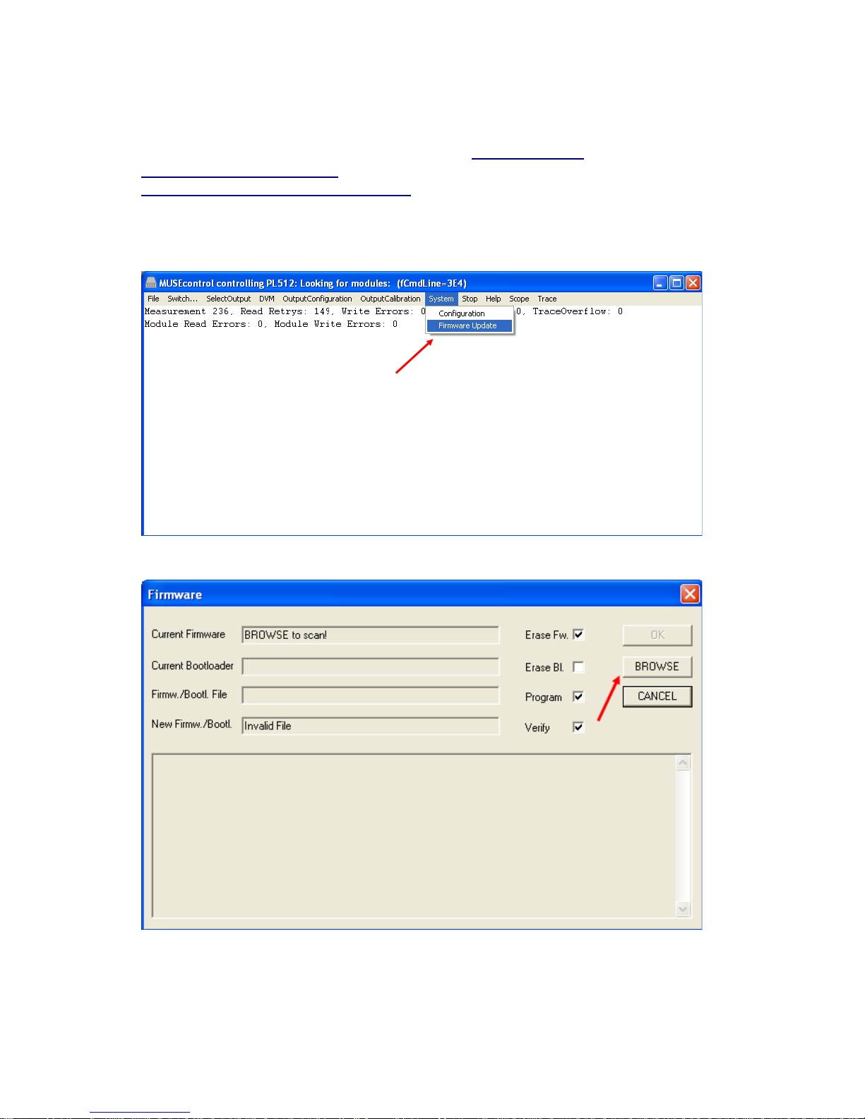
13 MPOD Firmware Update
For Bootloader from revision 1.5 and Firmware revision 2.*.0.15 and higher
1) In addition to the latest firmware files you need the MUSEcontrol program version 2.0.910.0 or higher.
All files can be download from the WIENER file server http://file.wiener-
d.com/software/MUSEcontrol/ and
http://file.wiener-d.com/firmware/MPOD/.
2) Connect the MPOD to the Computer via USB
3) Start the MUSEcontrol program and select the tab “system”. In the opened pull down menu select the
item “Firmware Update” to update the device via USB.
4) Hit the button “browse” to scan the device for current version of boot loader and firmware.
30. May 2018 61
Page 63
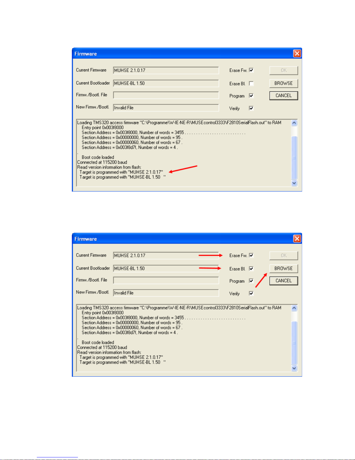
5) Check the version of the current firmware or boot loader. There are three options:
Option 1) Check “Erase Fw.” (erase firmware) and “Erase Bl.” (erase boot loader) if the current firmware
is older than 2.*.0.15 or it is a firmware without boot loader. After that push the button “browse” to scan
the flash. In some minutes select the new boot loader file in the automatically opened file menu. Press the
button “Ok”. Now the whole flash
will be erased and the new boot loader will be installed.
When the install process is done hit the button “cancel” to restart the system. It is recommended to close
the MUSEcontrol program before restarting.
A window which indicates a communication problem appears. The reason for this is that only the
bootloader without firmware is installed. Ignore this message by pushing the button “cancel”.
30. May 2018 62
Page 64
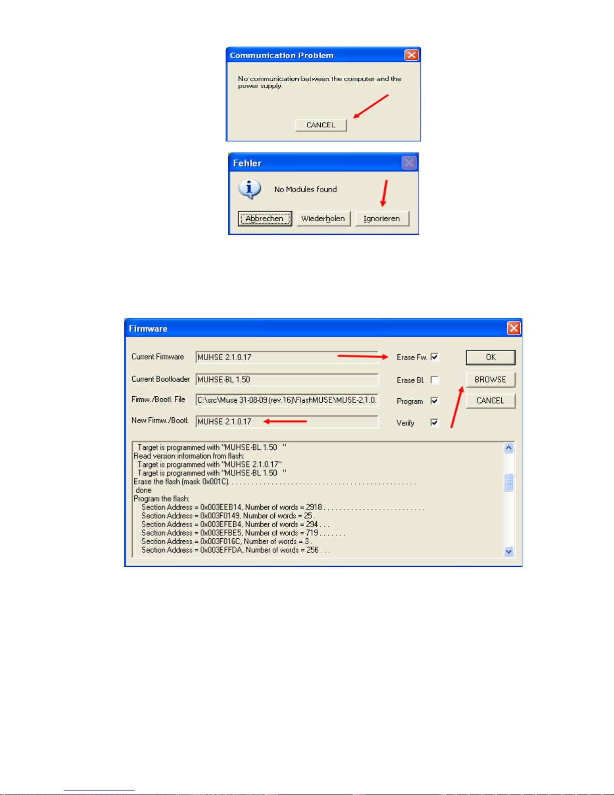
Also ignore the no modules message to hit the button “Ignorieren”.
Follow the step 1 and 2. Execute the instructions of option 2.
Option 2) Check “Erase Fw.” (erase firmware) if there no current, legal firmware is available or a newer
one should be installed. After that push the button “browse” to scan the flash. In some minutes select the
new firmware file in the automatically opened file menu. Press the button“Ok”. Now the firmware partition
in the flash will be
formatted and the new firmware will be installed.
When the install process is done hit the button “cancel” to restart the system. It is recommended to close
the MUSEcontrol program before restarting.
30. May 2018 63
Page 65
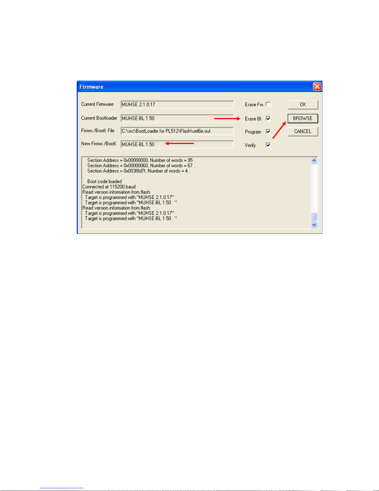
Option 3) Check “Erase Bl.” (erase boot loader) if there an older boot loader (from version 1.5) and a
newer one should be installed. If no boot loader is available chose option 1. After that push the button
“browse” to scan the flash. In some minutes select the new boot loader file in the automatically opened file
menu. Press the button“Ok”. Now the boot loader partition in the flash will be formatted and the new boot
loader will be installed.
When the install process is done hit the button “cancel” to restart the system. It is recommended to close
the MUSEcontrol program before restarting.
30. May 2018 64
Page 66
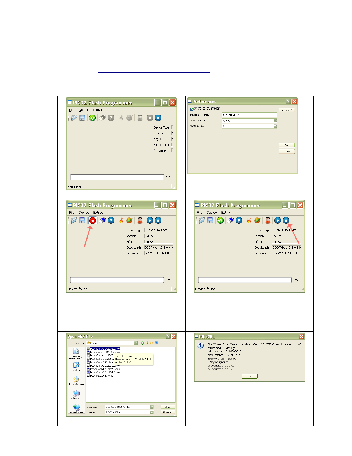
14 MPOD Display Firmware Update
MPOD display firmware update is possible with all displays using firmware Doom 1.0.1344.0 or
above (see http://file.wiener-d.com/firmware/MPOD-Display )
The update is done via Ethernet connected to the MPOD controller with the special utillity
PIC32PL.exe (http://file.wiener-d.com/software/PIC32BL )
Please install this software on your Windows PC start the program and perform the following
procedure:
Select „Extras → Preferences“
Enter MPOD IP address, and make sure the
checkbox „Connect via IP/SNMP“ is checked.
Then click „OK“.
Click „Device → Connect“ (green circle). The
connection to the display firmware is
established, and the icon changed to
„Disconnect“ (red circle with x)
Click the „Execute Boot Loader“ icon at the
right (blue circle with square). Normal
operation of the display is stopped and boot
loader operation is started.
Now use „File → Open“ select firmware file
The the new firmware is read from disk. The 2
warnings (ignored data) are correct.
30. May 2018 65
Page 67
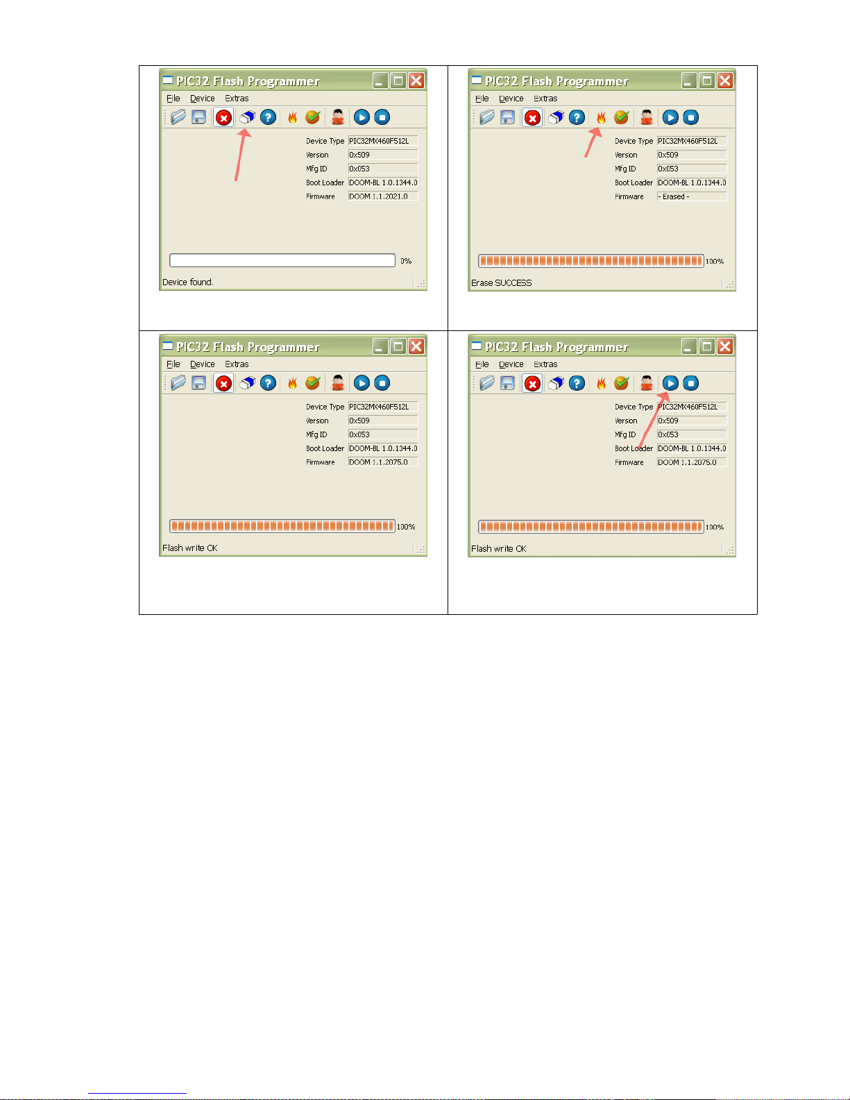
Click the „Erase“ icon to erase the previous
firmware.
Click „Program“ to program the new
firmware.
A verify is done automatically.
Now click the „Run new firmware“ icon (blue
circle with triangle) to leave the boot loader and
execute the new firmware.
30. May 2018 66
Page 68
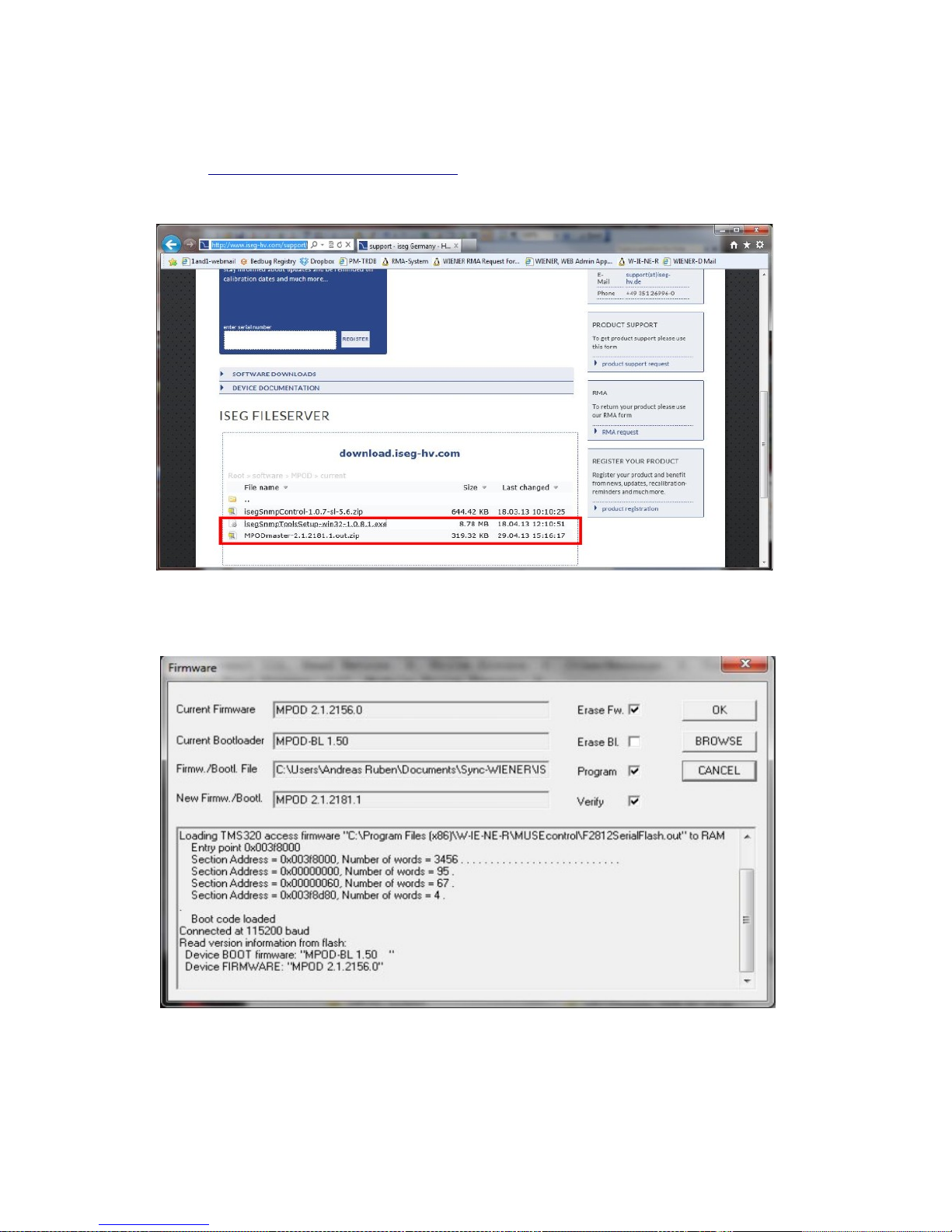
15 ISEG HV Module Firmware Update vias Ethernet / SNMP
Download ISEG SNMP tools and latest firmware from ISEG WEB-Site:
http://www.iseg-hv.com/support/
The firmware may have to be requested by providing HV module name / part number and serial
number
2. Perform MPOD firmware upgrade to MPODMaster 2.1.2181.1 or higher using MUSEcontrol
and the USB connection (see instructions in MPOD manual)
30. May 2018 67
Page 69
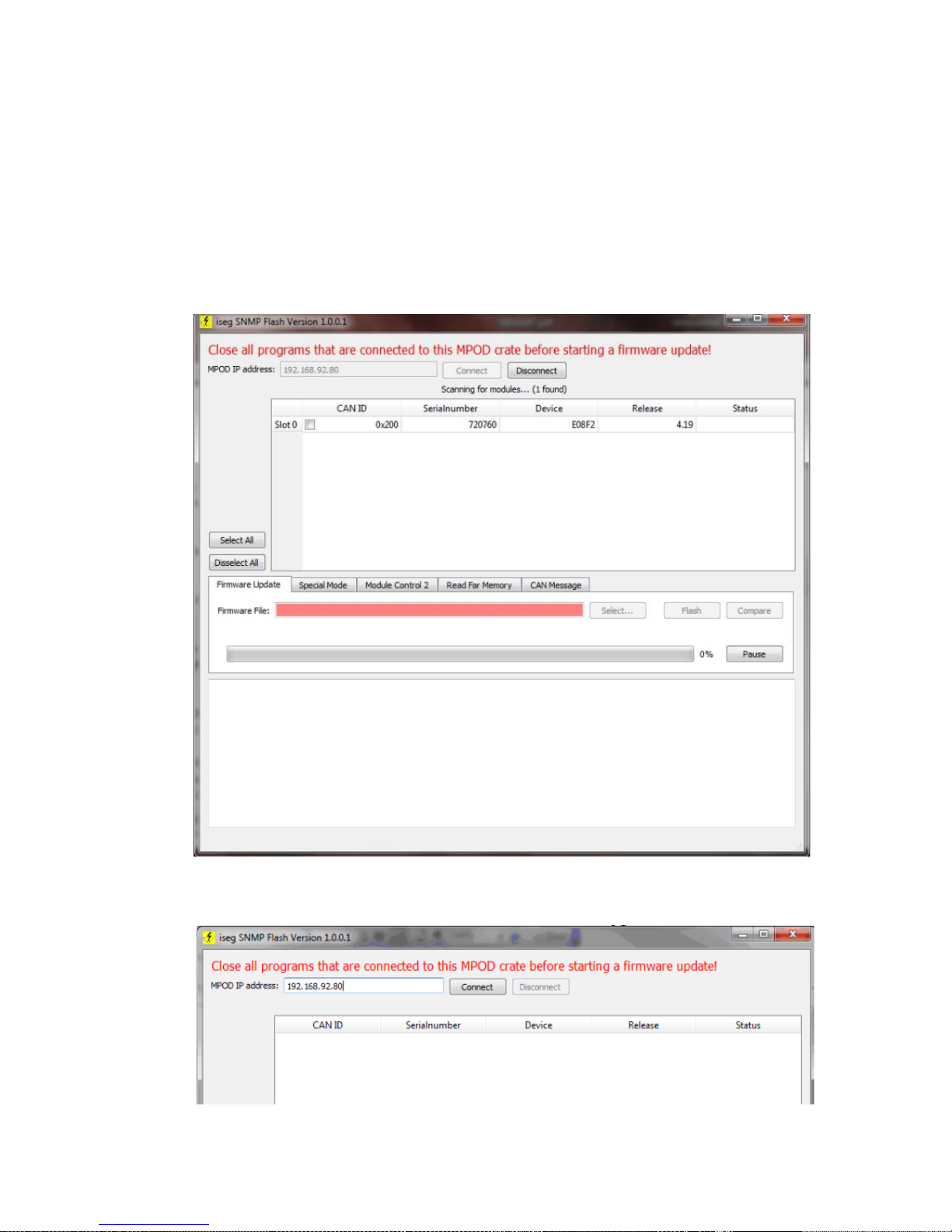
3. Run isegSnmpToolsSetup-win32-1.0.8.1.exe to install the ISEG software.
Remove all modules from the MPOD except the one you want to update (it's possible to update
multiple modules sequentially, but it is saver to start with only one first)
4. Close all programs that connect to the MPOD
5. Start isegSnmpFlash.exe
6. Please insert the correct MPOD IP address and click connect
7. A list of modules in this MPOD appears (in this case, only one)
8. Check the box in the column CAN ID to flash/firmware upgrade this module
30. May 2018 68
Page 70
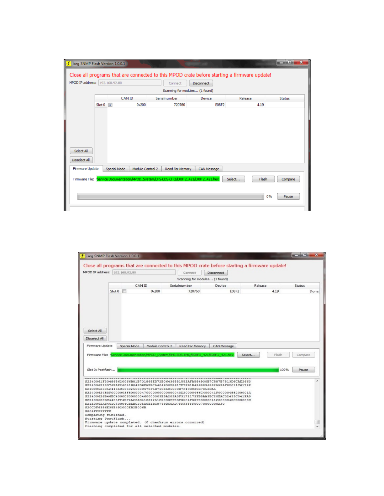
9. If the text field with the firmware name appears red, select the
HEX file with "Select..." either E08F2_421.hex (or other recommended firmware file)
10. Click Flash. The update consists of three steps: Flash, Compare and Postflash. After
Postflash, the Table shows "Done" in the status column.
30. May 2018 69
Page 71
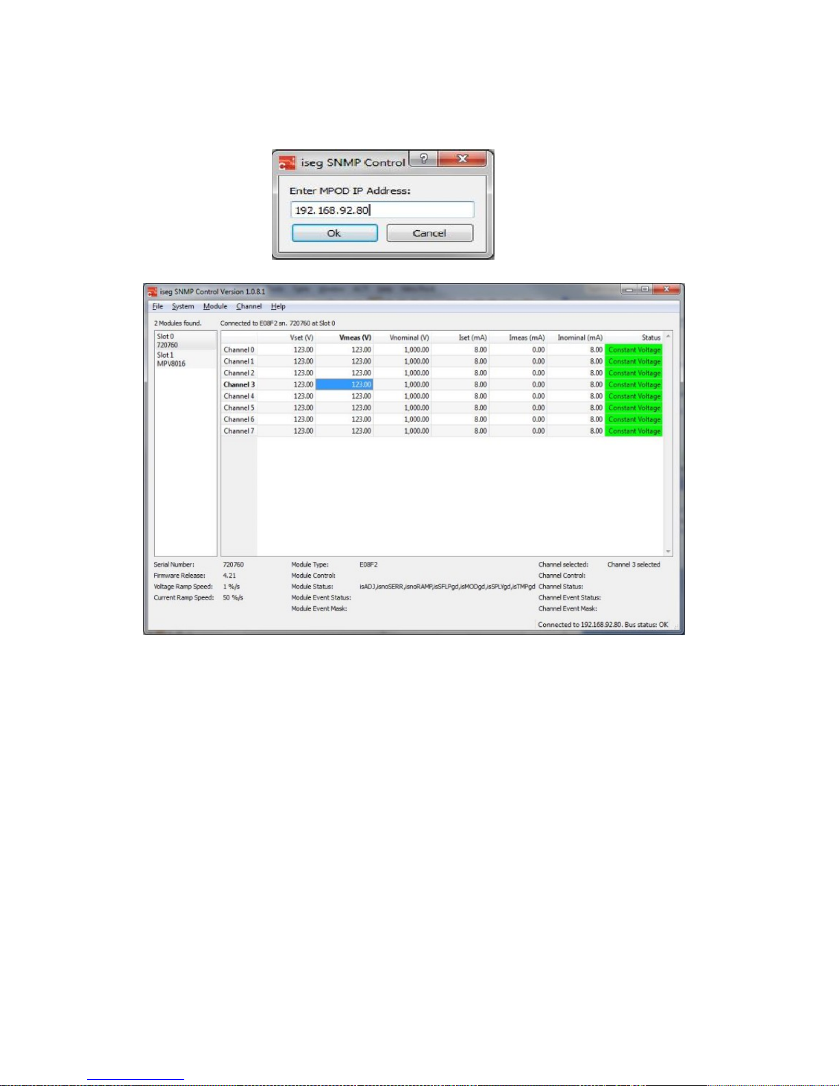
11. You can now close the program, re-power the MPOD and control it again with iseg SNMP
Control.
If anything goes wrong, e.g. the update stops and the progress bar is not moving for 2
minutes or more, you can close the program, re-power the MPOD and try again.
30. May 2018 70
Page 72
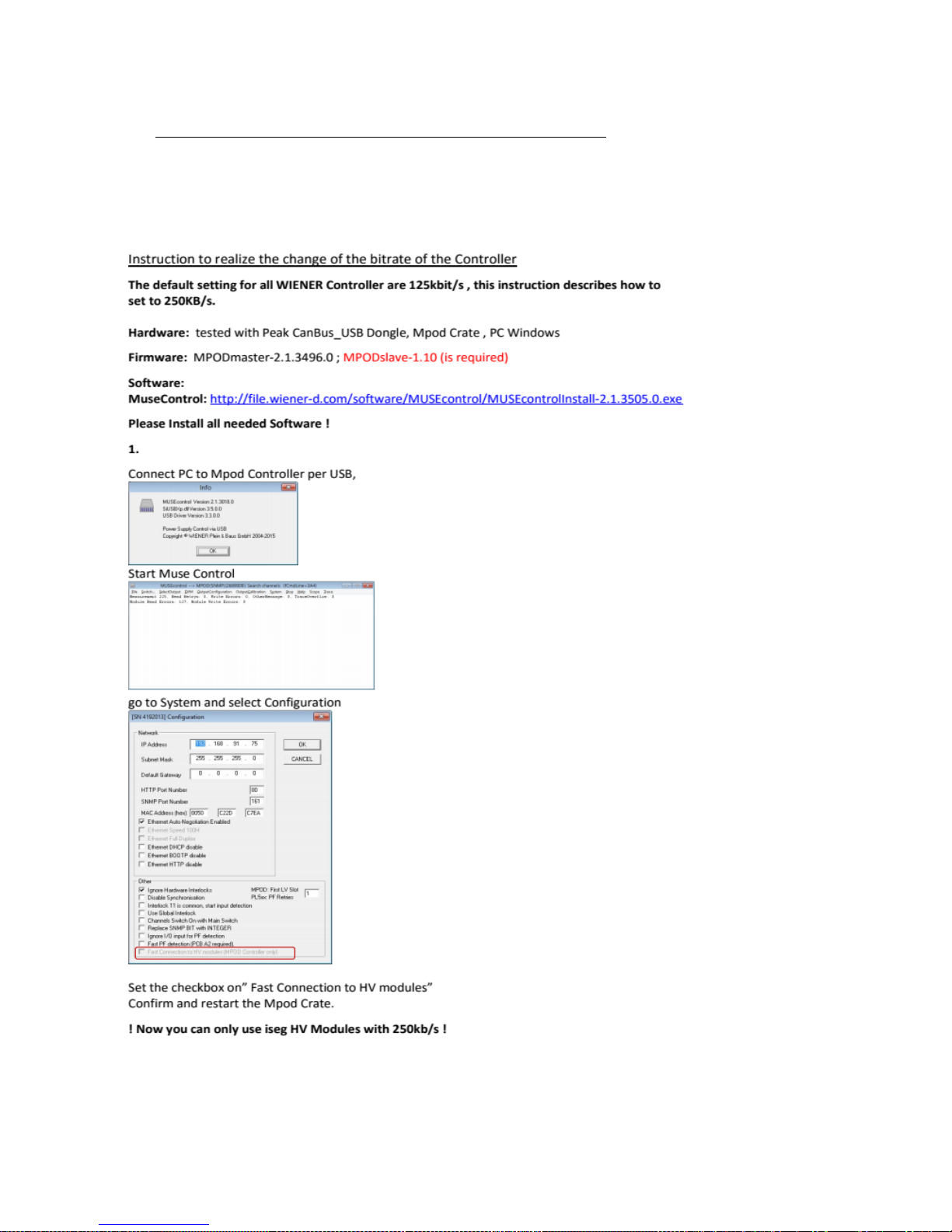
16 Instruction to change the Bitrate
Instruction to realize the change of the bitrate of the HV Module
The default setting for HV Modules with WIENER MPOD setup are 125kbit/s , this
instruction describes how to set to 250KB/s.
30. May 2018 71
Page 73
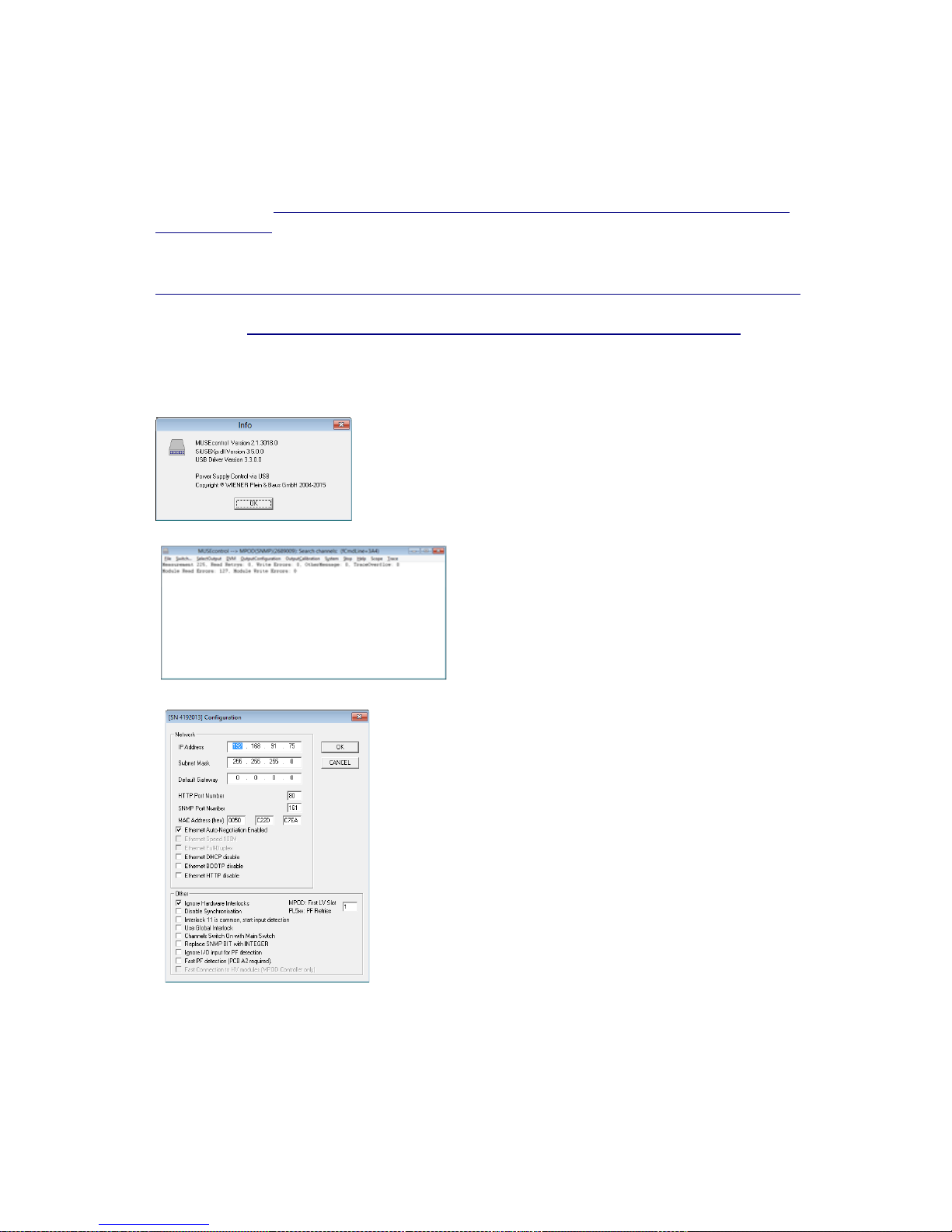
Hardware: tested with Peak CanBus_USB Dongle, Mpod Crate , PC Windows,
Firmware: MPODmaster-2.1.3496.0 ; MPODslave-1.10 (is required);
Software:
MuseControl: http://file.wiener-d.com/software/MUSEcontrol/MUSEcontrolInstall-
2.1.3505.0.exe
IsegCANHVControl:
http://download.iseg-hv.com/software/isegCANControl/current/isegCanTerminal.zip
included Peak driver (use only the driver from iseg because it is modified ),
PcanView http://www.peak-system.com/fileadmin/media/files/pcanview.zip
Please Install all needed Software !
1.
Connect PC to Mpod Controller per USB,
Start Muse Control
go to System and select Configuration
set the checkbox “disable synchronization”
Confirm and restart the Mpod Crate.
30. May 2018 72
Page 74
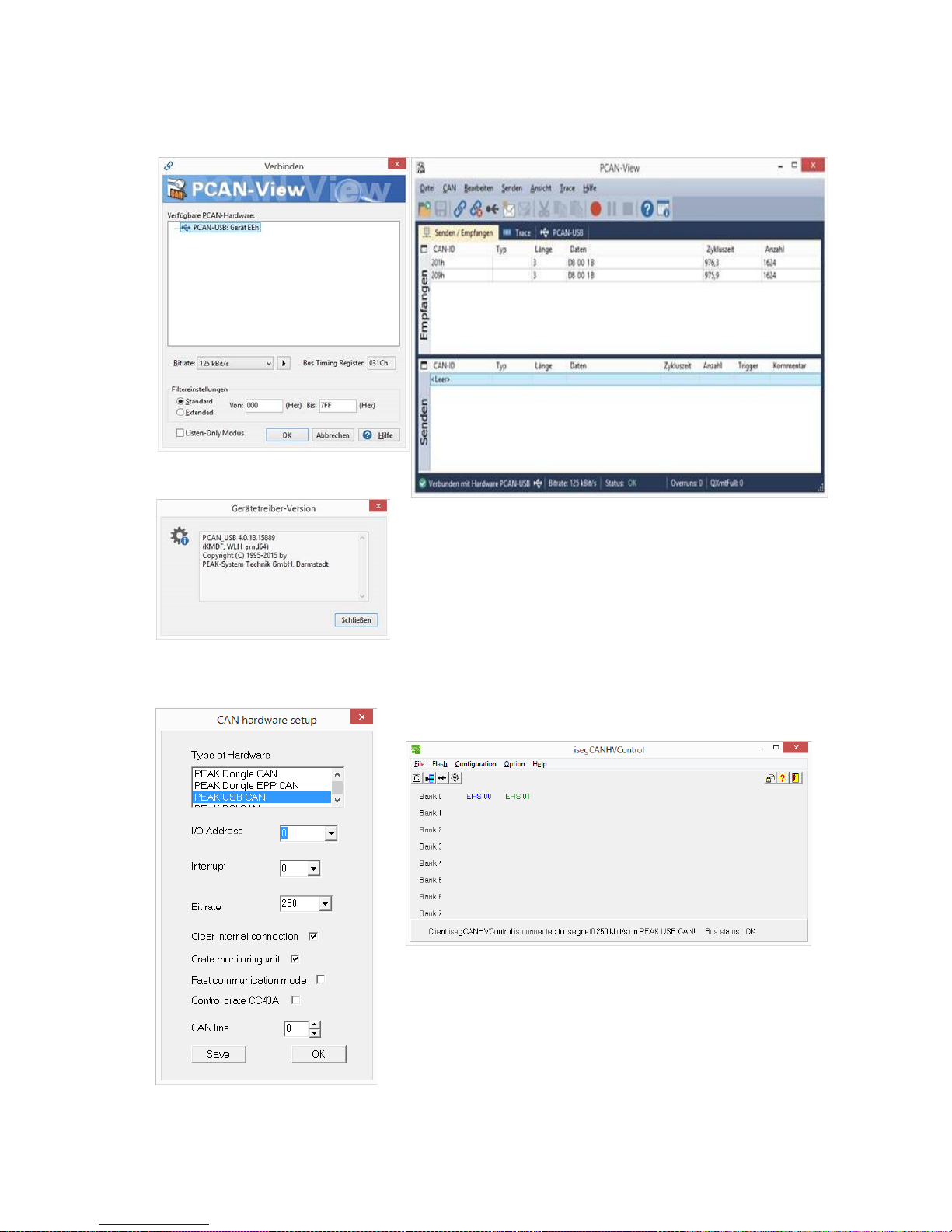
2.
Connect Mpod (CAN port)controller to PC (USB port)via CAN bus dongle.
The connection test with PCAN View of HV module:
Open iseg Can Control,
Select Peak USB CAN and select the current bit rate (HV module)
30. May 2018 73
Page 75
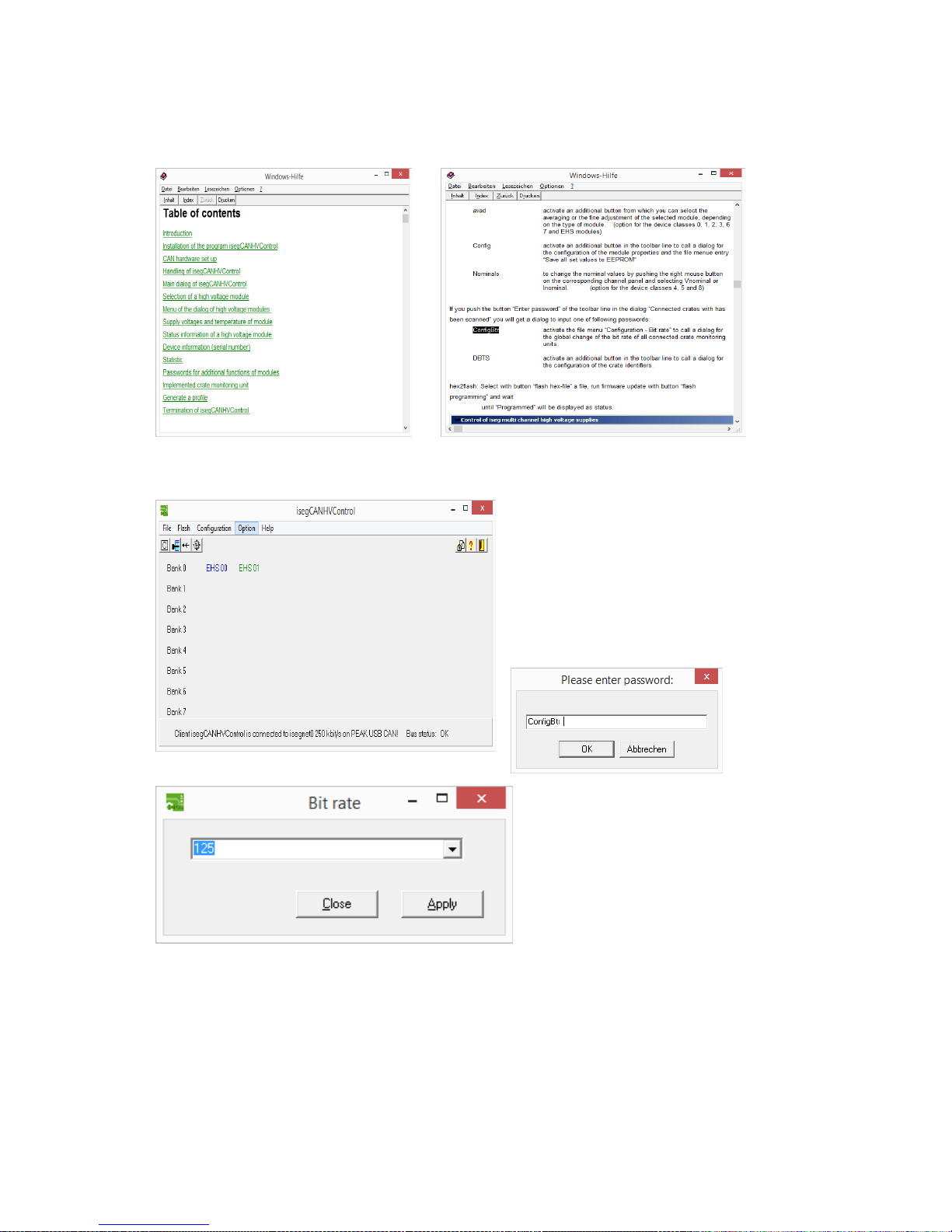
please copy corresponding password
and enter under Option Password.
Configuration: change bitrate on desired value and confirm
Now close IsegCanHVcontrol , open Muse Control and disable „Disable
Synchronisation” (as point 1.)
Restart the Mpod Crate. Ready!
30. May 2018 74
 Loading...