

Page 1
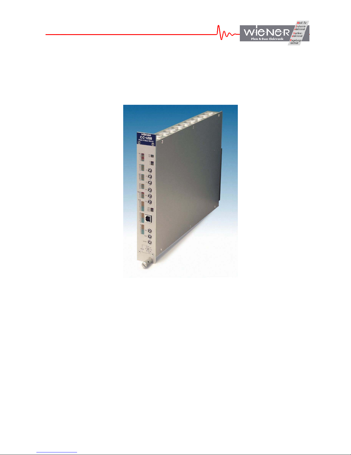
CC-USB
User Manual
WIENER, Plein & Baus GmbH 1 www.wiener-d.com
Page 2

General Remarks
The only purpose of this manual is a description of the product. It must not be interpreted a
declaration of conformity for this product including the product and software.
W-Ie-Ne-R revises this product and manual without notice. Differences of the description in
manual and product are possible.
W-Ie-Ne-R excludes completely any liability for loss of profits, loss of business, loss of use
or data, interrupt of business, or for indirect, special incidental, or consequential damages of
any kind, even if W-Ie-Ne-R has been advises of the possibility of such damages arising
from any defect or error in this manual or product.
Any use of the product which may influence health of human beings requires the express
written permission of W-Ie-Ne-R.
Products mentioned in this manual are mentioned for identification purposes only. Product
names appearing in this manual may or may not be registered trademarks or copyrights of
their respective companies.
No part of this product, including the product and the software may be reproduced,
transmitted, transcribed, stored in a retrieval system, or translated into any language in any
form by any means with the express written permission of W-Ie-Ne-R.
CC-USB and VM-USB are designed by JTEC Instruments.
WIENER, Plein & Baus GmbH 2 www.wiener-d.com
Page 3

Table of contents:
1 General Description........................................................................................................ 5
1.1 CC-USB Features.................................................................................................... 5
1.2 Read-out Modes ...................................................................................................... 5
1.3 CC-USB Front panel............................................................................................... 6
1.4 Technical data ......................................................................................................... 6
1.5 Power Consumption................................................................................................ 6
1.6 Block diagram ......................................................................................................... 7
2 CC-USB and USB driver installation............................................................................ 8
2.1 Installation for Windows Operating Systems....................................................... 8
2.2 Installation for Linux Operating Systems .......................................................... 11
3 General Architecture of CC-USB and its User Interface.......................................... 12
3.1 Register Block........................................................................................................ 12
3.1.1 Firmware ID Register ..................................................................................... 12
3.1.2 Global Mode Register..................................................................................... 12
3.1.3 Delays Register ............................................................................................... 13
3.1.4 Scaler Readout Frequency Register................................................................ 13
3.1.5 User LED and NIM Output Selectors............................................................. 13
3.1.6 LAM Mask Register ....................................................................................... 15
3.1.7 Action Register ............................................................................................... 15
3.1.8 Serial Number Register................................................................................... 15
3.2 CAMAC Command Stacks .................................................................................. 15
3.3 CAMAC NAF Generator ..................................................................................... 15
3.4 USB In FIFO ......................................................................................................... 15
4 Communicating with CC-USB..................................................................................... 16
4.1 General structure of Out Packets........................................................................ 17
4.2 Writing Data to the Register Block ..................................................................... 17
4.3 Reading Back Data from the Register Block...................................................... 17
4.4 Writing Data to the CAMAC Command Stacks and to the NAF Generator.. 18
4.5 Structure of the CAMAC Stack........................................................................... 18
4.6 CAMAC common functions................................................................................. 20
4.7 Structure of the IN Packets.................................................................................. 20
5 Guide to List Mode Data Acquisition with CC-USB ................................................. 22
6 LIBXXUSB Library for Windows and Linux............................................................ 23
6.1 xxusb_devices_find ............................................................................................... 23
6.2 xxusb_device_open................................................................................................ 23
6.3 xxusb_device_close................................................................................................ 24
6.4 xxusb_reset_toggle ................................................................................................ 24
6.5 xxusb_register_write............................................................................................. 25
6.6 xxusb_register_read.............................................................................................. 25
6.7 xxusb_stack_write................................................................................................. 26
6.8 xxusb_stack_read.................................................................................................. 27
WIENER, Plein & Baus GmbH 3 www.wiener-d.com
Page 4

6.9 xxusb_stack_execute............................................................................................. 27
6.10 xxusb_usbfifo_read............................................................................................... 28
6.11 xxusb_bulk_read................................................................................................... 29
6.12 xxusb_bulk_write.................................................................................................. 30
6.13 xxusb_flashblock_program.................................................................................. 31
WIENER, Plein & Baus GmbH 4 www.wiener-d.com
Page 5

1 GENERAL DESCRIPTION
The CC-USB is a full-featured CAMAC Crate controller with integrated high speed USB
interface. It supports Master and Slave operations with full CAMAC arbitration; as a master
it accepts slaves. The CC-USB is FASTCAMAC compliant. The CC-USB internal FPGA
can be programmed to operate as command sequencer with data buffering in a 22kB size
FiFo. Combined with the front panel I/O ports this allows CAMAC operation and data taking
without any PC or USB activity.
All CC-USB logic is controlled by the XILINX Spartan 3 family FPGA. Upon power-up the
FPGA boots from a flash memory. The configuration flash memory can be reprogrammed
via the USB port, allowing convenient updates of the firmware. The integrated CAMAC
dataway display as well as additional LED’s for the controller / USB provide all necessary
system information.
1.1 CC-USB Features
• high speed USB2 interface, auto-selecting USB2/USB1
• 3 user-programmable NIM inputs (with LEMO connectors)
• 3 user-programmable NIM outputs (with LEMO connectors)
• Visual data and status display with 54 red, green, and yellow LEDs (N, F, A, R / W
Data, Q, X, C, Z)
• user definable / host-controlled readout modes
• Readout triggered either via USB link, or by a programmable combination of LAMs,
or by a start signal applied to a (programmable) NIM input
• 22-kByte of pipelined data buffer (FIFO) with programmable level of transfer trigger
• FASTCAMAC level 1 compatible
1.2 Read-out Modes
• Single word transfer (16- or 24- bit)
• Q-stop (repeated readout of the same A and N until Q=0 is returned)
• Q-scan (repeated readout with A and N increment until Q=0 is returned)
• Autonomous (intelligent) readout pursuant to user-programmed stack, 1k of 16-bit
stack memory
• conditional readout gated by 16-bit hit register (quadruple OR of 16-fold ANDs of hit
bits and programmable mask bits)
• optional (slot-by-slot) wait-for-LAM with programmable LAM timeout
• optional (slot-by-slot) skipping of S2 strobe (500ns cycles)
• stack supports Q-stop and address-scan mode entries
• stack supports FASTCAMAC mode entries
• optional readout of subaddresses identified in a previously fetched address pattern
WIENER, Plein & Baus GmbH 5 www.wiener-d.com
Page 6
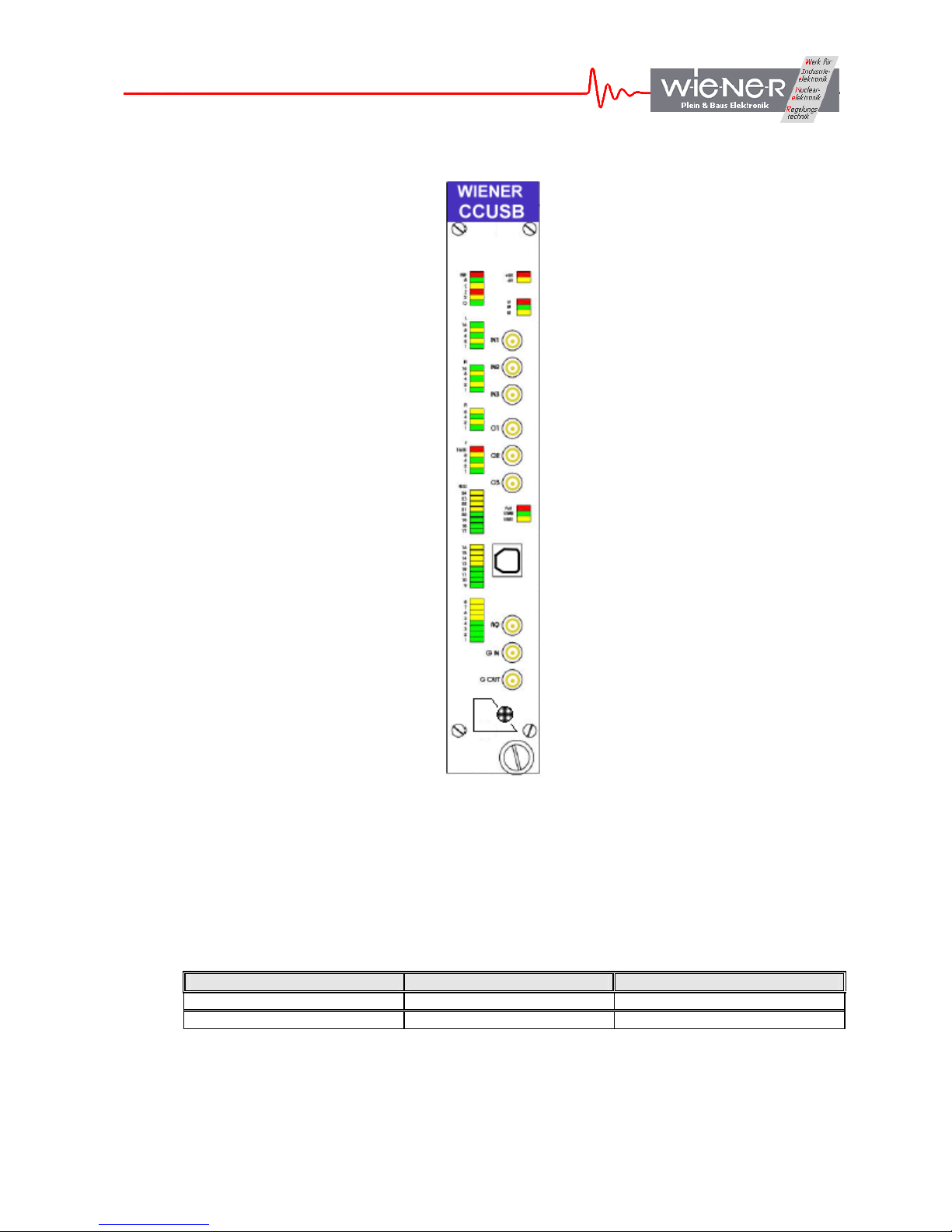
1.3 CC-USB Front panel
)
INH, B, Q, X, C, Z LED’s
LAM (L1, L2, L4, L8, L16) LED’s
Station (N1, N2, N4, N8, N16) LED’s
Sub-Address (A1, A2, A4, A8) LED’s
Function (F1, F2, F4, F8, F16) LED’s
Data (9,10,11,12,13,14,15) LED’s
Data (9,10,11,12,13,14,15) LED’s
Data (1,2,3,4,5,6,7,8) LED’s
1.4 Technical data
1.5 Power Consumption
Voltage Max. current Power
+6 V 1.2 A about 8 W
-6 V 0.1 A
Power LED for +6V / -6V
3 user LED’s (red, green, yellow
3 user inputs Lemo / NIM
3 user outputs Lemo / NIM
Failure LED / USB 1 or 2 indicator
USB port
Aux Controller RQ, G-in / G-out
Firmware selector (1 – 4) :
P1 – P4 for programming
C1 – C4 for use / operation
WIENER, Plein & Baus GmbH 6 www.wiener-d.com
Page 7
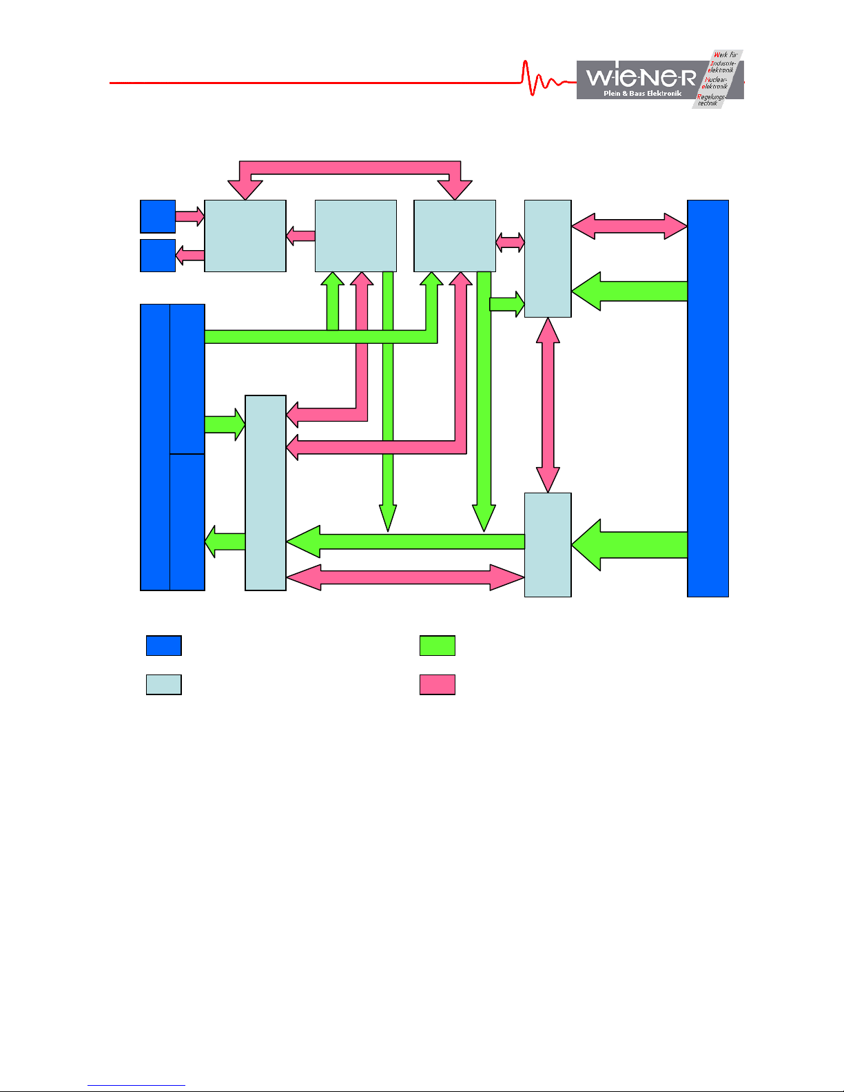
1.6 Block diagram
ACQ
REG STACKS
External to
Data
FPGA
Control
I1 - User NIM input
O1 - User NIM "Busy" output
ACQ - Data Acquisition Control
REG - Register Block
STACKS - CAMAC Command Stacks (2 kBytes)
NAF - NAF Sequence Generator
CAMAC - CAMAC Bus, Including Arbitration
FIFOs - Three-Stage Piplined FIFO Array (22 kBytes)
Master - Control Unit
USB Controller - FX2 CY7C68013 IC
OUT FIFO - USB Out FIFO (Relative to Host)
IN FIFO - USB In FIFO (Relative to Host)
WIENER, Plein & Baus GmbH 7 www.wiener-d.com
Page 8
2 CC-USB AND USB DRIVER INSTALLATION
ATTENTION!!! Observe precautions for handling:
• Electrostatic device! Handle only at static safe work stations. Do not touch electronic
components or wiring
• The CAMAC crate as well as the used PC have to be on the same electric potential. Different
potentials can result in unexpected currents between the CC-USB and connected computer which
can destroy the units.
• Do not plug the CC-USB into a CAMAC crate under power. Switch off the CAMAC crate first
before inserting or removing any CAMAC module! For safety reasons the crate should be
disconnected from AC mains.
2.1 Installation for Windows Operating Systems
1. Switch off the CAMAC crate and remove the power cord. Plug in the CC-USB on the far
right slots (normally slot 24 & 25) and secure it with the front panel screw. Switch on the
CAMAC crate.
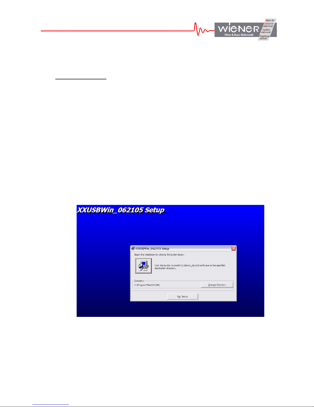
2. Insert the driver and software CD-ROM into the CD-ROM drive of the computer and run
the setup program in the XXUSBWin_Install folder. Define directory for installation and
click the installation button.
3. Connect the CC-USB via the provided USB cable to a USB port of the computer. Running
Windows 2000 or XP the hardware change should be detected and the “New Hardware
Wizard” Window should open and show the CAMAC USB controller.
4. Do not use the automatic software installation but chose “installation from specific
location”.
WIENER, Plein & Baus GmbH 8 www.wiener-d.com
Page 9
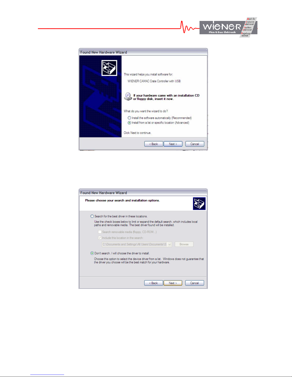
5. Select manual search for the driver
6. Type in the drive letter for the CD-ROM (e.g. D:, F:, …) and locate the file CC-USB.inf.
Press Enter to select this driver and to close the window.
7. The WIENER CC-USB driver should be listed and highlighted in the driver list. The driver
is not digitally signed which however does not have any effect on it’s functionality. Press
Next to finish the installation.
WIENER, Plein & Baus GmbH 9 www.wiener-d.com
Page 10
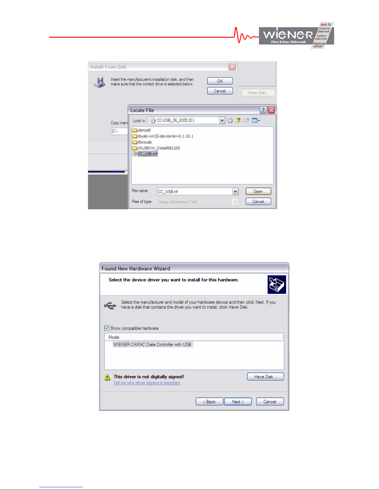
8. The “New Hardware Wizard” should copy all driver files into the Windows System32
folders and report a successful installation.
WIENER, Plein & Baus GmbH 10 www.wiener-d.com
Page 11
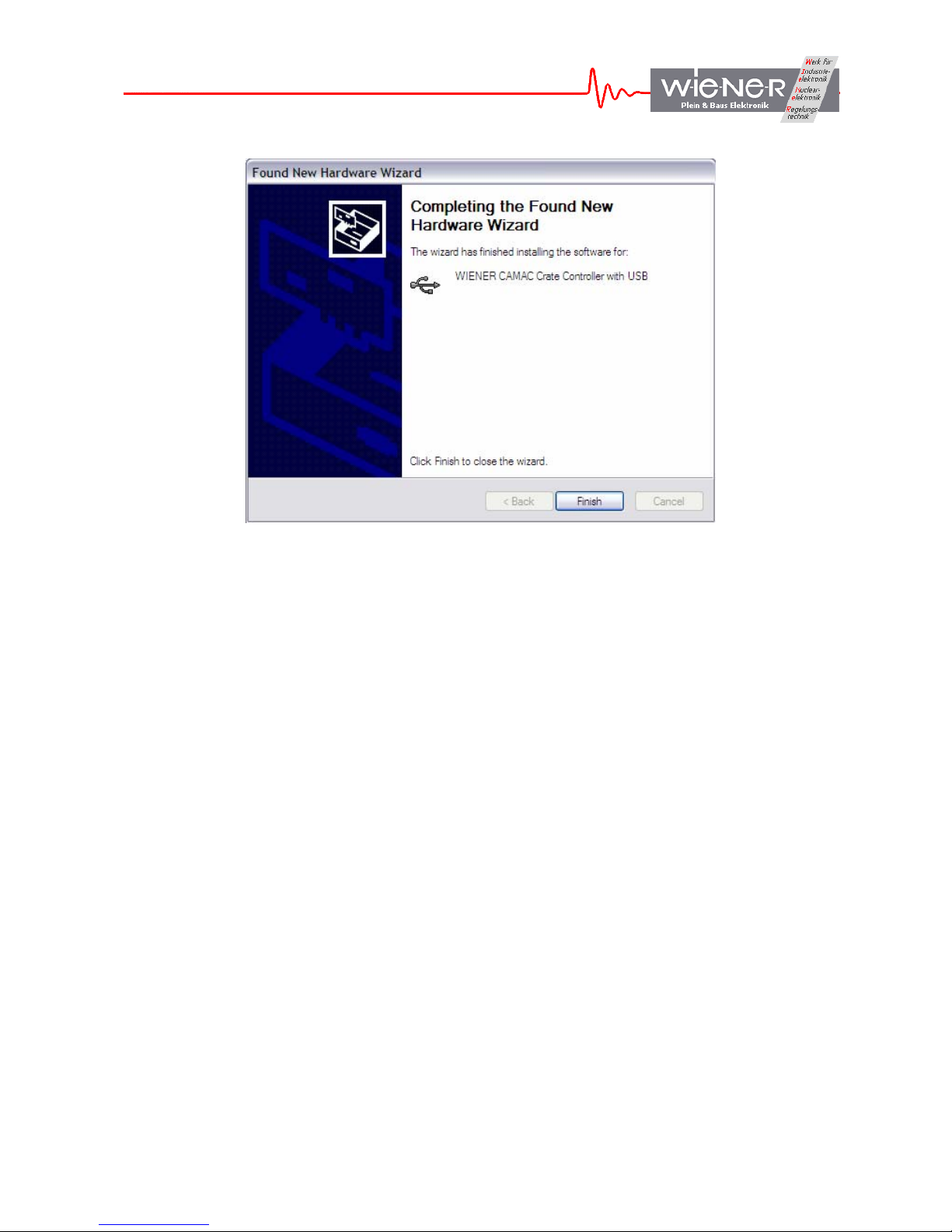
9. Run the XXUSBWin.exe program from the program directory or use one of the sample
programming packages to communicate with the CC-USB.
2.2 Installation for Linux Operating Systems
Linux provides a library libusb that allows to perform the bulk transfer to and from the CCUSB and VM-USB USB port. The documentation and the library is available from
http://libusb.sourceforge.net. Fortunately, it is also included in modern Linux distributions, as
is the USB2 EHCI driver.
The prerequisites are:
(i) EHCI driver loaded - this is part of newer Linux distributions
(ii) libusb installed - installed automatically with newer Linux distributions.
IMPORTANT NOTE: At the time of this writing, root privileges are needed to use libusb,
when hot-plugging the device. This is needed for being able to write to the usb file system
usbfs. Please execute su before calling the demo program.
WIENER, Plein & Baus GmbH 11 www.wiener-d.com
Page 12
3 GENERAL ARCHITECTURE OF CC-USB AND ITS USER INTERFACE
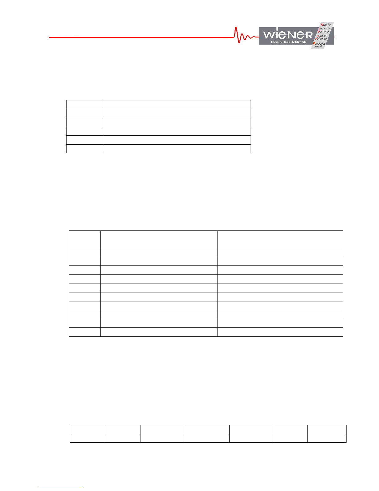
The CC-USB presents to the user five internal devices or addresses shown in Table 1:
Table 1. Internal devices of CC-USB and their addresses
Address Device
1 Register Block (RB)
2 CAMAC Data Readout Stack (CDS)
3 CAMAC Scaler Readout Stack (CSS)
4 CAMAC NAF Generator (CNAF)
5 Common Output Buffer
3.1 Register Block
The Register Block of CC-USB is composed of a number of registers identified by subaddresses as shown in Table 2:
Table 2. Register sub-addresses and their functionality
Sub-
Register Note
address
0 Firmware ID Read-only
1 Global Mode Read/Write
2 Delays Read/Write
5 Scaler Readout Frequency Read/Write
6 User LED Source Selector Read/Write
7 User NIM Output Source Selector Read/Write
8 LAM Mask Read/Write – 24-bits in two words
10 Action Read/Write
12 CAMAC LAM 24-bits Read-Only
13 Serial Number 11 bits, Read-Only
3.1.1 Firmware ID Register
This Firmware ID register identifies the acting FPGA firmware in four hexadecimal digits
MYFR, where M and Y represent the month and year of creation, and F and R represent the
firmware and revision numbers, respectively.
3.1.2 Global Mode Register
The global mode register has the following 16-bit structure:
13-15 12 9-11 8 6 4,5 0 - 3
Unused Arbitr. WdgFreq HeaderOpt EvtSepOpt Unused BuffOpt
WIENER, Plein & Baus GmbH 12 www.wiener-d.com
Page 13
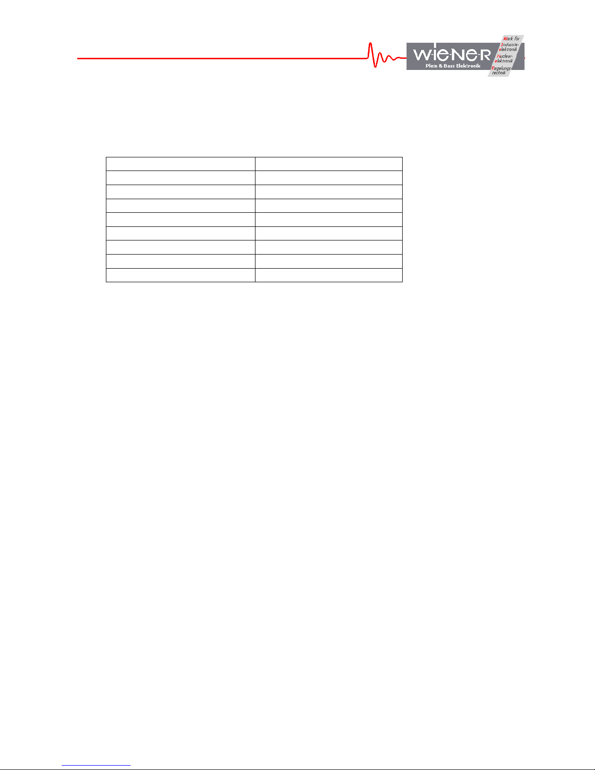
The BuffOpt bits (0-2) define the output buffer length. Bit 3 controls the mode of buffer
filling, such that 0 closes buffers at event boundaries and 1 allows spreading events across
the adjacent buffers:
BuffOpt Value Buffer Length (words)
0 4096
1 2048
2 1024
3 512
4 256
5 128
6 64
7 Single Event
The EvtSepOpt set the number of event terminator word (hexadecimal FFFF), such that
EvtSepOpt=0/1 cause one/two terminator word/s written at the end of each event.
The HeaderOpt bit controls the structure of the buffer header, such that HeaderOpt=0 writes
out one header word identifying the buffer type (bit 15=1 – watchdog buffer, bit 14=0 – data
buffer, bit 14=1 – scaler buffer) and the number of events in buffer. When HeaderOpt = 1,
the second header word is written out listing the number of words in the buffer.
The WdgFreq bits define the frequency at which the watchdog is forcing writing of output
buffer during data acquisition. The three bit number represents the time interval in seconds,
counting from the end of an event, after which the watchdog triggers when no new event has
been observed.
The Arbitr Bit, when set to 1 activates CAMAC bus arbitration.
3.1.3 Delays Register
The delays register stores the desired trigger delay (from the start signal applied to the NIM
input to the actual start of the CAMAC readout) – least significant 8 bits and the LAM
timeout period – most significant 8 bits. Both delays are in units of us.
3.1.4 Scaler Readout Frequency Register
The Scaler Readout Frequency Register stores the number defining the frequency at which
scalers are to be read out (scaler stack is executed) during the data acquisition. The stored
value is equal to the number of data events separating the scaler readout events. When the
value is zero, scaler readout is suppressed.
3.1.5 User LED and NIM Output Selectors
Numbers stored in these registers identify sources of User LEDs and NIM Outputs. The
actual selection of sources is firmware specific and subject to customization. The general bit
composition of the selector word is shown in the table below
WIENER, Plein & Baus GmbH 13 www.wiener-d.com
Page 14
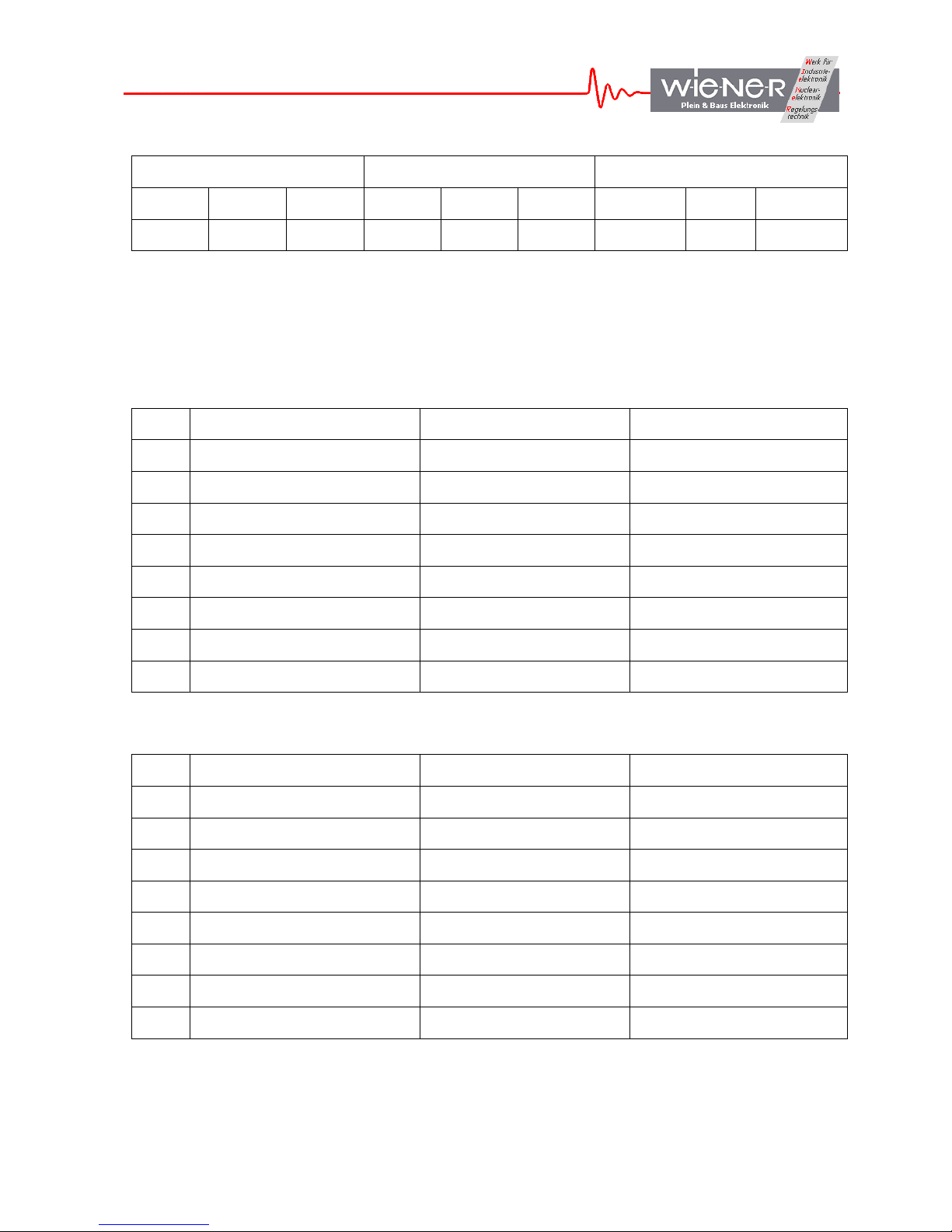
Yellow LED and NIM O3 Green LED and NIM O2 Red LED and NIM O1
14 13 10-12 9 8 5-7 4 3 0-2
Latch Invert Code Latch Invert Code Latch Invert Code
The 3-bit code identifies the source of the signal. The sources differ for different LEDs and
NIM outputs, but they are the same between the LED and NIM targets (i.e., Red LED has the
same sources as the NIM output O1, Green LED the same as O2, and Yellow LED the same
as O3) For firmware 4503, the sources are as follows:
Code Red LED Green LED Yellow LED
0 Event Trigger Acquire NIM I3
1 Busy Camac F1 Busy
2 USB Trigger Reserved NIM I2
3 USB Out FIFO not empty Event Trigger Camac S1
4 USB In FIFO not full Data Buffer Full Camac S2
5 Reserved Reserved USB In FIFO not empty
6 Acquire NIM I1 Executing scaler stack
7 Camac F2 USB In FIFO not empty USB Trigger
Code NIM O1 NIM O2 NIM O3
0 Busy Event Trigger EndOfBusy
1 Event Trigger Camac F1 Busy
2 USB Trigger Reserved NIM I2
3 USB Out FIFO not empty Event Trigger Camac S1
4 USB In FIFO not full Data Buffer Full Camac S2
5 Reserved Reserved USB In FIFO not empty
6 Acquire NIM I1 Executing scaler stack
7 Camac F2 USB In FIFO not empty USB Trigger
WIENER, Plein & Baus GmbH 14 www.wiener-d.com
Page 15

Note 1. “Busy” signal indicates that stack processing is in progress, with Camac operations
not being completed. “Busy” is asserted when event readout is triggered and deasserted as
soon as Camac operations are completed.
Note 2. “Acquire” idicates that the data acquisition mode is active.
Note 3. “USB Trigger” is generated in response to writing to bit 1 of Action Register.
Note 4. “Event Trigger” indicates that event readout has been triggered.
Note 5. Invert bit causes the signal to be inverted
Note 6. Latch bit causes the signal to be latched. To release the latch one must toggle the bit.
3.1.6 LAM Mask Register
The LAM Mask Register is a 24-bit register that stores the LAM Mask defining what
combination of LAM’s triggers event readout during the data acquisition. When zero, the
readout is triggered by a signal applied to the NIM input.
3.1.7 Action Register
Bit 0 of the Action Register activates data acquisition in list mode, when event readout is
triggered either by a start signal applied to the User NIM input I1 or a combination of LAMs
coinciding with the LAM mask.
Writing “1” to Bit 1 of the Action Register generates an internal signal of 150ns duration,
called USB Trigger. The bit is, in actuality, never set, i.e., requires no resetting. This signal
can be routed to user NIM output O1 or O3 and/or displayed on user Red or Yellow LED.
Bit 2 of the Action Register clears a number of internal registers and is intended for primarily
for use during firmware debugging.
3.1.8 Serial Number Register
The Serial Number Register is a Read-Only register containing the serial number of the CCUSB. The serial number can be also obtained during the initialization of the USB port, e.g.,
by calling the libxxusb library function xxusb_devices_find.
3.2 CAMAC Command Stacks
3.3 CAMAC NAF Generator
3.4 USB In FIFO
WIENER, Plein & Baus GmbH 15 www.wiener-d.com
Page 16

4 COMMUNICATING WITH CC-USB
Communication with the CC-USB consists in writing and reading of buffers of data to/from
the USB2 port of the CC-USB using bulk-transfer mode. Borrowing from the USB language,
the buffers to be written to the CC-USB will be called Out Packets, and they are sent to pipe
0 of the USB port. The buffers to be read will be called In Packets, and they are read from
pipe 2 of the USB port.
The USB controller IC, when connected to a USB2 port configures packet lengths to 512
bytes. For USB1 (full speed), the packet length is set to 64 bytes. The Out Packets must be
properly formatted to be understood by the internal devices of CC-USB and, by the same
token, the format of the In Packets retrieved from the CC-USB must be understood by the
user in order to be useful.
User may send Out Packets to four devices – the Register Block (RB), CAMAC Readout
Stacks (CDS and CSS), and the NAF Generator (RB, CDS, CCS, CNAF). User may read In
Packets only from the Common Output Buffer. Reading back data from the RB, CDS, and
CSS is achieved by, first sending a data request Out Packet to these devices and then by
reading the In Packet containing the requested data from the Common Output Buffer.
Writing to the CAMAC NAF Generator constitutes implicitly a request for data, such that in
response to such a writing, CC-USB performs the requested CAMAC operation and returns
the CAMAC data in the Common Output Buffer. Both, In and Out Packets are of a variable
length, depending on which internal address is involved and what the content of the message
is.
Important Note:
With some drivers (EZUSB in conjunction with Windows API), read operations from the
USB port are blocking operations such that the host program will stop executing until the
data are available at the port. Therefore, the host program must make sure (by first requesting
data) that CC-USB has placed data in the Common Output Buffer (physically this is the
FIFO of the USB controller IC), before the read command is issued. CC-USB provides a
mechanism for supplying data, even when the host program is “frozen” in a state of waiting
for data. The mechanism consists in starting a second copy of the program and issuing a bare
request for data command from this second copy, not followed by the read IN Packet
command.
The libxxusb package of CC-USB access functions makes overlapped USB calls that have
preset timeout periods. When no data is available until the end of this period, the I/O is
canceled and the respective function returns error code. The user is then expected to take
proper actions, which may include resubmitting the call.
It is important to specify a sufficiently long In Packet size to be at least of the size of the
actual data buffer available at the Common Output Buffer. This is especially important in the
case of reading CAMAC data buffers which differ in size substantially depending on the
structure of the CAMAC Readout Stack.
WIENER, Plein & Baus GmbH 16 www.wiener-d.com
Page 17

4.1 General structure of Out Packets
Since internally, the USB controller of the CC-USB is set up as a 16-bit wide FIFO (First- InFirst-Out Memory), the In and Out Packets are organized as collections of 16-bit words. For
the purpose of the software, and more specifically, of the Windows Application
Programming Interface (API) routines, the data are packed in byte-wide buffers, a process
that may remain transparent to the user when proper set of routines (DLLs) is used. Also,
much of the technical information on writing and reading back data from the internal devices
of the CC-USB may be considered redundant, when a set of routines is available to perform
the task. This information is, however, necessary for writing such routines.
First (16-bit) word in an Out Packet identifies the internal device/address for which the
packet is intended and whether the packet represents a request for data or represents the data
to be stored/interpreted to/by the target device. The latter information is coded in bit 3
(value=4) of the header word, with bit 3 set for requests for data. The meaning of the second
word in the Out Packet depends on the address and represents the sub-address in the case of
the Register Block and the number of words to follow, in the case of the CAMAC Stacks
(CDS and CSS) and the CAMAC NAF Generator (CNAF). The subsequent words in the
buffer, if any, represent the data to be stored in the target device or the data to be interpreted
and acted upon by the target device (in the case of the CNAF). A detailed description of Out
Packets for the four target devices is given below.
4.2 Writing Data to the Register Block
The Out Packet for writing data to various registers of the Register block is composed of the
following words:
1. Target Address = 1 the target address identifying the register block
2. Register Sub-Address sub-address of a particular register in the block (see Table 2,
further above).
3. Data To be Written a 16-bit data word.
In the case of the LAM mask register (sub-address 8), additional 8 bits are sent in the
additional, fourth word:
4. High Bits of the Data 16-bit data word containing.
4.3 Reading Back Data from the Register Block
To read back data from the Register block, one must first send a request Out Packet to the
Register Block consisting of two words:
1. Target Address + 4 = 5 the target address of the Register Block + the data request bit
(bit 3)
2. Register Sub-Address sub-address of the register of interest (see Table 2.)
WIENER, Plein & Baus GmbH 17 www.wiener-d.com
Page 18

4.4 Writing Data to the CAMAC Command Stacks and to the NAF Generator
The Out Packets targeting the two CAMAC Stacks and the CAMAC NAF Generator have
identical structure, differing only in the Target Address and in length:
1. Target Address 2, 3, or 8, for CDS, CSS, and CNAF, respectively
2. Number of words in the stack
3-N. Sequence of stack words where N=Number of words in stack + 2
The CAMAC Data Stack (Address=2) is 768 words deep and is intended for storing
information on the sequence of the CAMAC commands to be performed when an event
readout is initiated. The CAMAC Scaler Stack (Address=3) is 256 words deep and is
intended for storing information on the sequence of the scaler readout commands, when a
periodic readout of scalers is desired. The CAMAC NAF Generator (Address 8) is an internal
module that interprets the information found either in the CAMAC Stacks (when CC-USB is
in data acquiring mode) or in the Out Packet received from the USB port (when CC-USB is
in interactive mode).
4.5 Structure of the CAMAC Stack
The CAMAC stack consists of a sequence of properly encoded simple (one line for CAMAC
“Read” commands and 3 lines for CAMAC “Write” commands) or complex (multi-line)
CAMAC commands.
Simple commands specify only the desired N, A, and F to be issued by CC-USB and,
additionally, whether the data is 24-bits (Long Mode) or 16-bits long For the CAMAC
“Write” commands, additional two lines specify the data to be written.
The data word for a simple command has the following structure:
15 14 9-13 5-8 0-4
0 Long Mode N A F
This data word can thus be calculated as
SimpleCommand = F+32*A+512*N+16384*LongMode
Note, that the CAMAC “Read” commands have both bits 3 and 4 (the most significant bits)
of F set, while the “Write” commands have only bit 4 set. Control commands have bit 3 set.
Complex commands are possible only for “Read” operations. The first word of a complex
commands is similar to a simple command, except that it has bit 15 (continuation bit) set, i.e.
WIENER, Plein & Baus GmbH 18 www.wiener-d.com
Page 19
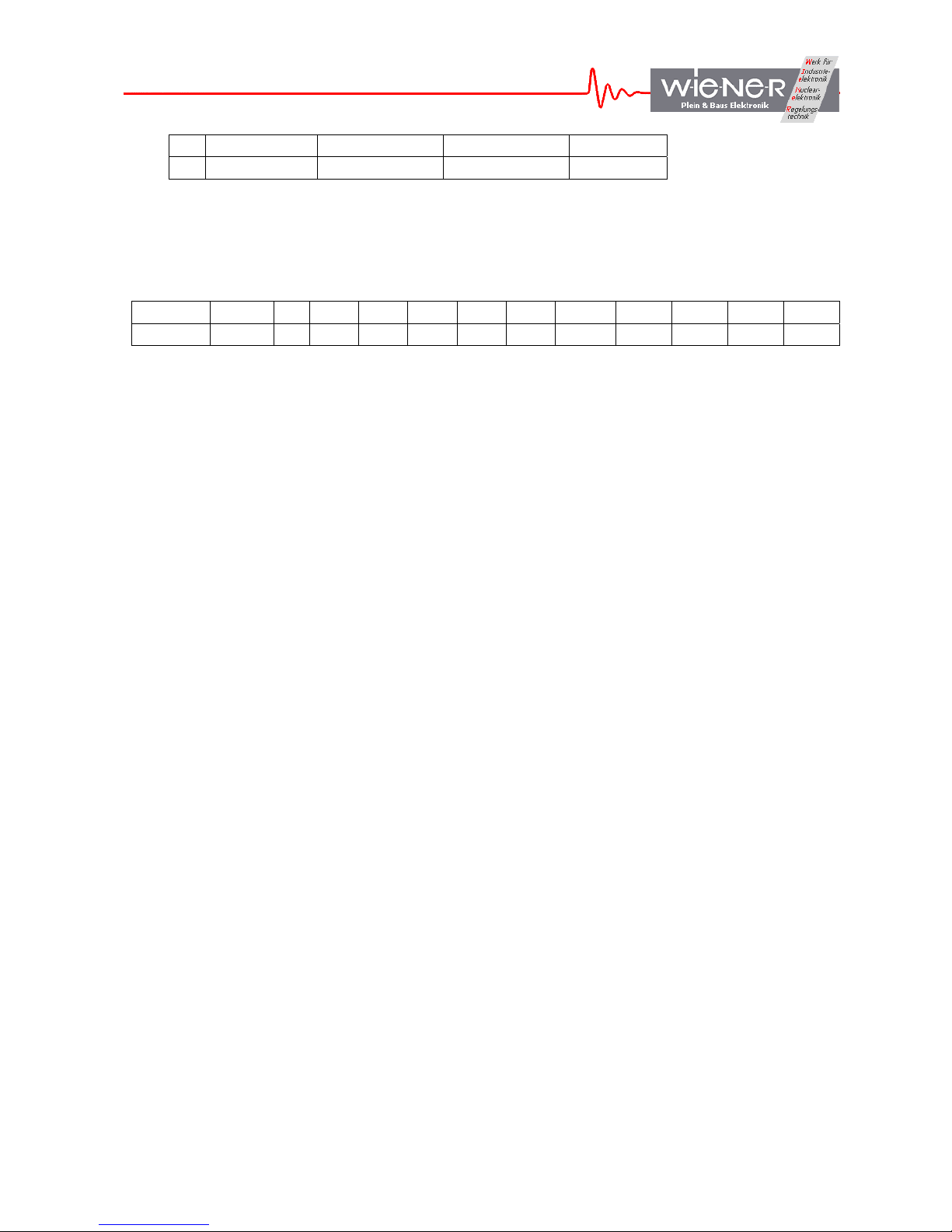
15 14 9-13 5-8 0-4
1 Long Mode N A F
The second word is a modifier word, detailing the mode of readout to be performed or the
nature of the data to be read. Depending on which bits in the second word are set, a number
of additional words, if any, will follow. The continuation bit (bit 15) of the second word is set
whenever additional data are to follow. The structure of the modifier word is as follows:
14-15 12-13 11 9 8 7 6 5 4 3 2 1 0
U NT U AP FC LM RM AS QS HM ND S2 HD
Where the individual bits have the following meaning:
HD Hit Data - identifies the data as a 16-bit hit register data (coincidence register data), to
be used for the conditional readout of subsequent CAMAC modules. The hit register
must be the first module to be read out, i.e., the HD bit may be set only in the first
word of the CAMAC readout stack (CDS).
S2 When set, S2 strobe is suppressed, the CAMAC cycle ending at the end of S1
ND Numbers Data - identifies the data as representing the number of times the next
command in stack has to be performed.
HM Hit Mode - instructs the NAF Generator to condition the readout with the content of
the hit pattern read in the first command of the stack (first command in an event). The
Number of Product Terms used to condition the readout must be specified as well.
QS Q-stop mode – the command is to be repeated as long as Q=1 (Q response from the
addressed CAMAC module), but not more than the number specified in the following
stack line..
AS Address Scan – the command is to be repeated a number of times specified in the
following word of the stack, with A incremented by 1 each time.
RM Repeat Mode – repeat command a number of times specified in the following stack
line.
LM LAM Mode – wait for LAM, subject to LAM Timeout and perform the readout only
when LAM is set.
FC Fast CAMAC Mode – perform the readout in Fast CAMAC mode a number of times
specified in the following stack line.
AP Address Pattern Data – identifies the data as an address pattern to be used in
conjunction with the command that follows. The subsequent command will be
repeated for every address for which the bit is set in the address pattern data word.
NT Number of Product Terms – specifies the number of words in the stack that follow
and that constitute bit masks for constructing a logical equation used in deciding
whether the given operation is to be performed for the particular hit register data.
WIENER, Plein & Baus GmbH 19 www.wiener-d.com
Page 20
The following rules apply:
(i) Whenever the Repeat Mode (RM), Address Scan (AS), Q-Stop, or FC bit is set, the stack
line must be followed by another line defining the maximum number (11-bit number) of
times the command is to be repeated.
(ii) When the Hit Mode (HM) bit is set, the Number of Terms bits must be declared. The
stack line must be followed by the specified number of data lines representing bit masks
BMask(1 to NT), to be used in constructing the logical condition for performing the
command. The logical equation is:
[BMask(1) AND HD = BMask(1)) OR (BMask(2)
AND HD = BMask(2)) OR (BMask(3)
AND HD = BMask(3)) OR (BMask(4)
AND HD = BMask(4)],
i.e., the command will be performed whenever all bits in any of the specified Bit Maks are
set in the hit register data.
Since the stack can be quite complex, it is advisable to write a proper routine to set up the
stack. As an option, one may utilize the CC-USBWin Windows application to build the stack
and save it to disk.
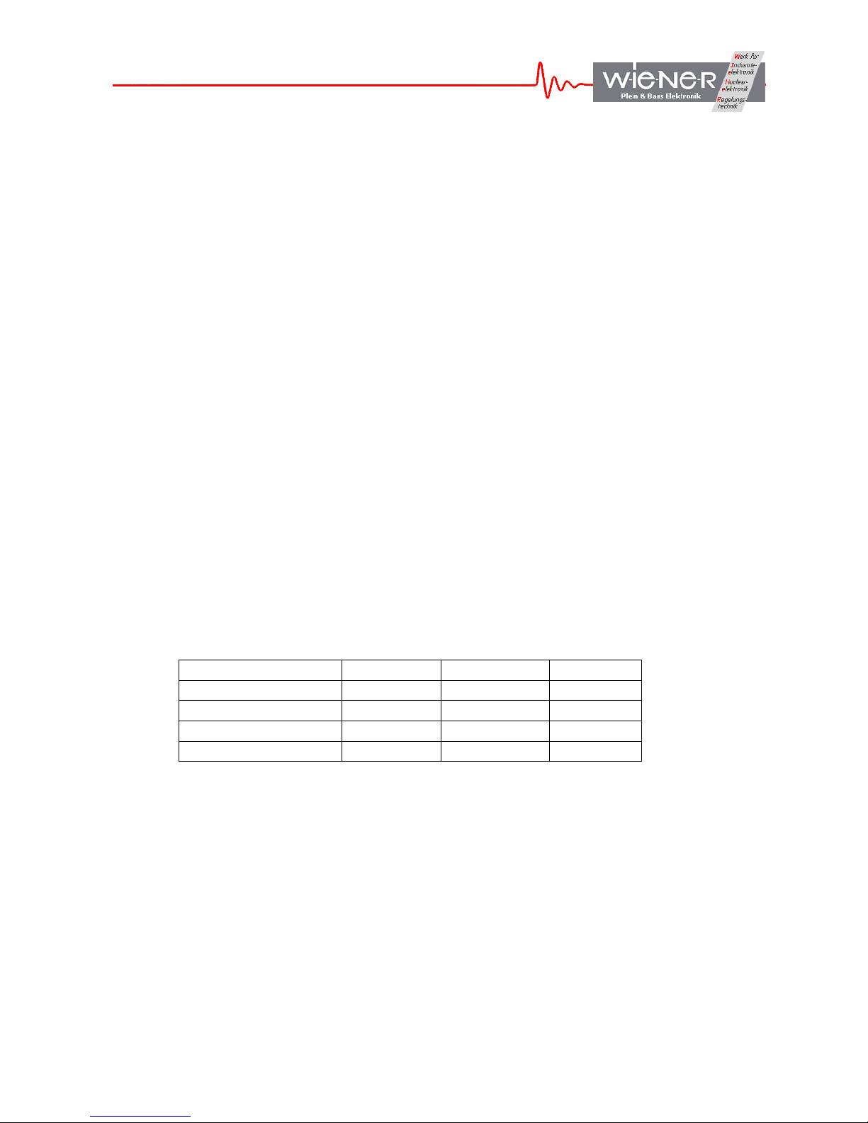
4.6 CAMAC common functions
The common CAMAC controller functions as Initialize (Z), Clear (C) and Inhibit (I) are
realized via NAF calls to “internal” station numbers N=28 and 29. These functions can be
programmed as follows
Function N A F
Z
C
Set Inhibit
Clear Inhibit
28 8 29
28 9 29
29 9 24
29 9 26
4.7 Structure of the IN Packets
The General Output Buffer is associated with Endpoint 6 of the USB2 controller IC, which is
configured as a 512 byte deep FIFO. This endpoint is configured for bulk transfer and one
can specify lengths of buffers to be read of any length (up to 8192 bytes) compatible with
the CC-USB functionality. Al data supplied by the CC-USB is to be read from the Endpoint
6. While reading, it is important to specify the length of the buffer not shorter than the length
of the actual data buffer written by the CC-USB into this endpoint.
WIENER, Plein & Baus GmbH 20 www.wiener-d.com
Page 21

The structure of data retrieved in conjunction with direct requests for data addressed to the
Register Block and to the CAMAC Stacks is simple, such that the buffer consists only of the
requested data.
The data buffers read during the data acquisition process have a structure depending on the
mode of buffering, i.e., whether event data are allowed to span two buffers (bit 3 of BoffOpt
set). Additionally, there are special rules for treating long events. These are discussed at the
end of this section.
For the Integer Event Mode, the data buffer has the following structure:
1. Header word Bit 15 set indicates a watchdog buffer, bit 14 set indicates a
scaler buffer. Bits 0 – 9 represent the number of events in the
buffer.
2. Optional 2nd Header Word Bits 0-11 represent the number of words in the buffer.
3. Event Length Event length including terminator words.
4-N1. Event Data
N2. Event Terminator hexadecimal FFFF
N3. Optional 2nd Terminator hexadecimal FFFF
.
. Subsequent Events
.
N5. Buffer Terminator hex FFFF
The unpacking of the events must be done in accordance with the CAMAC Stack that is
involved in generating the buffer.
In the Split-Event mode, when events span two or more buffers, no buffer terminator is
written.
For the direct access of the CAMAC NAFGEN (Interactive CAMAC operations), no header
words are written and the In Packet contains only one event.
CC-USB has dedicated 2kWords-long event FIFO to assemble events. To handle longer
events, CC-USB splits the long event into parts, each of which appears as a separate event in
the output buffer. The partial events are distinguishable by bit 12 of the Event Length word
set, except for the last part. Also, only the last “installment” is terminated by the Event
Terminator word (s).
CC-USB has a provision to automatically change the output buffer packing mode to SplitEvent mode, whenever the Event Length exceeds the length of the Integer-Event buffer. The
fact of such a change is indicated by setting of bit 13 in the buffer header word.
WIENER, Plein & Baus GmbH 21 www.wiener-d.com
Page 22

5 GUIDE TO LIST MODE DATA ACQUISITION WITH CC-USB
CC-USB is intended for use in list mode data acquisition, where it performs sequences of
desired CAMAC operations pursuant to stack(s) stored in it, upon receipt of event trigger.
CC-USB then formats the data read form the CAMAC bus and buffers them in a data buffer.
When the buffer is full, CC-USB transfers its content to the In FIFO of the USB controller IC
for a readout by host software.
To set up CC-USB for data acquisition in list mode one nedds to do the following:
1. Build the regular stack by adding all the desired simple and complex commands to it.
One must make sure that the stack sequence will clear all CAMAC modules. It is
recommended to first execute the stack from the host software to verify that it
performes as intended. One may use here the libxxusb library function
xxusb_stack_execute.
2. Load the stack into the CC-USB memory, e.g., by calling the libxxusb library
function xxusb_stack_write. It is recommended to read back the stack (function
xxusb_stack_read), to verify that the stack is correctly stored.
3. When the setup calls for it, build and load the scaler stack.
4. Set up the data acquisition trigger mode. By default, CC-USB commences execution
of the stack upon receipt of a NIM signal at its user NIM input I1.
5. Set the trigger delay (time from the receipt of an event to the commencement of the
stack execution) and LAM timeout.
6. Set up event termination mode. By default, CC-USB terminates every event by one
terminator word 0xFFFF.
7. Set up buffering mode and data buffer length by writing a suitable 4-bit code into bits
0-3 of the Global Mode Register. The default is buffer length of 4096 words and
events fitting into one buffer.
8. Set up CAMAC bus arbitration, if necessary. The default is no arbitration.
9. Set buffer header option. By default, CC-USB writes one buffer header word
containig information on the number of events in the buffer, buffer type (regular, or
periodic scaler), and the buffer termination mode (regular or watchdog).
10. Start acquisition by setting bit 0 of the Action Register to 1. End acquisition by
resetting this bit to “0”. While in acquisition mode, the host software is expected to
read the USB port In FIFO in a loop, to empty it and make space for subsequent
events.
WIENER, Plein & Baus GmbH 22 www.wiener-d.com
Page 23

6 LIBXXUSB LIBRARY FOR WINDOWS AND LINUX
A dedicated library of functions was developed to facilitate the utilization of CC-USB and its
VME counterpart, VM-USB. This library is called libxxusb and requires the libusb0.sys
driver to be installed. It is in fact a wrapper library for the general-use libusb-win32 library
available via www.sourceforge.net
at no charge.
All xxusb functions for both 32-bit MS Windows (Win98SE, WinME, Win2k, WinXP) as
well as for Linux rely on the USB library “libusb-win32”(Windows) or “libusb” (Linux). For
further details about these libraries please see www.sourceforge.net
http://sf.net/projects/libusb/
.
or
6.1 xxusb_devices_find
The xxusb_devices_find function retrieves relevant parameters of USB ports of all XX-USB
devices attached to the host and returns these in an array of proper structures. This is the first
command to be issued when attempting to establish communication with an XX-USB.
WORD xxusb_devices_find{
XXUSB_DEVICE_TYPE lpXXUSBDevice,
};
Parameters
lpXXUSBDevice
[out] Pointer to an array of structures storing parameters of all XX-USB devices
identified.
Return Values
On success, the function returns the number of XX-USB devices found, including 0.
A negative return value indicates that the handle to a valid device could not be opened as a
result of insufficient privileges. It is recommended to retry in Superuser mode.
6.2 xxusb_device_open
The xxusb_device_open function obtains handle to the desired XX-USB device, identified by
xxusb_devices_find command. This is the second command to be issued when attempting to
establish communication with an XX-USB. The obtained handle is then to be used while
calling various xxusb_*_* functions, that require the handle. Upon termination of a XX-USB
session, the handle is to be released by calling xxusb_handle_close.
WORD xxusb_device_open{
USB_DEVICE_TYPE lpUSBDevice,
};
Parameters
lpUSBDevice
WIENER, Plein & Baus GmbH 23 www.wiener-d.com
Page 24

[in] Pointer to a structure storing parameters of the target XX-USB devices.
Return Values
On success, the function returns the handle to the target XX-USB device. A negative return
value indicates that the handle to a valid device could not be opened as a result of insufficient
privileges. It is recommended to retry in Superuser mode.
Remarks
While all xxusb functions rely on the libusb (www.sourceforge.net) functions while
communicating with XX-USB, xxusb_device_open and xxusb_handle_close are simply
macros creating aliases to usb_open and usb_close functions of the libusb library.
6.3 xxusb_device_close
The xxusb_device_close function closes the handle to the desired XX-USB device, obtained
by a xxusb_device_open call. This function is to be called upon termination of an XX-USB
session.
WORD xxusb_device_close{
USB_DEV_HANDLE lpUSBDevice,
};
Parameters
lpUSBDevice
[in] Pointer to a variable containing the handle to be closed.
Return Values
Returns negative upon failure.
Remarks
While all xxusb functions rely on the libusb (www.sourceforge.net
) functions while
communicating with XX-USB, xxusb_device_open and xxusb_handle_close are simply
macros creating aliases to usb_open and usb_close functions of the libusb library.
6.4 xxusb_reset_toggle
The xxusb_reset_toggle function toggles the reset state of the FPGA while XX-USB is in
programming mode – rotary selector set in one of four P* positions.
WORD xxusb_reset_toggle{
HANDLE hDevice,
};
Parameters
WIENER, Plein & Baus GmbH 24 www.wiener-d.com
Page 25

hDevice
[in] Handle to the XX-USB device.
Return Values
Returns negative upon failure.
6.5 xxusb_register_write
The xxusb_register_write sends a data buffer to XX-USB, causing the latter to store the
desired data in the target register.
WORD xxusb_register_write{
HANDLE hDevice,
WORD wRegisterAddress,
DWORD dwRegisterData
};
Parameters
hDevice
[in] Handle to the XX-USB device.
wRegisterAddress
[in] Address of the XX-USB register.
For a list of XX-USB addresses, see Remarks
dwRegisterData
[in] Data to be stored in the register.
Return Values
On success, the function returns the number of bytes sent to XX-USB.
Function returns 0 on attempted writes to read-only registers and negative numbers on
failures.
6.6 xxusb_register_read
The xxusb_register_read function first, sends a buffer to XX-USB, causing the latter to write
the content of a desired register to its USB port FIFO and then, obtains the value by reading
the buffer from the XX-USB.
WORD xxusb_register_read{
HANDLE hDevice,
WORD wRegisterAddress,
LPDWORD lpRegisterData
};
Parameters
WIENER, Plein & Baus GmbH 25 www.wiener-d.com
Page 26

hDevice
[in] Handle to the XX-USB device.
wRegisterAddress
[in] Address of the XX-USB register.
For a list of XX-USB addresses, see Remarks
lpRegisterData
[out] Pointer to a variable that receives the data returned by the operation, i.e., the value
stored at wRegisterAddress of XX-USB.
Return Values
On success, the function returns the number of bytes read XX-USB. Valid values are 2 and 4,
with the latter only for LAM Mask and LAM registers.
Function returns a negative number on a failure.
6.7 xxusb_stack_write
The xxusb_stack_write function sends a buffer to XX-USB, causing the latter to store this
content in a dedicated block RAM, for use when data acquisition mode is active. This content
can be read back using xxusb_stack_read function.
WORD xxusb_stack_write{
HANDLE hDevice,
WORD wStackType,
LPDWORD lpStackData
};
Parameters
hDevice
[in] Handle to the XX-USB device.
wStackAddress
[in] Type of the XX-USB stack, the content of which is to be read. Valid types are 0,
for the regular stack and 1, for the periodic (scaler) readout stack.
lpStackData
[in] Pointer to a variable array that contains the data to be stored in the target stack.
Return Values
On success, the function returns the number of bytes sent to XX-USB. The latter value is
twice the length of the stack plus 2 (for a header word identifying a stack as a target).
Function returns a negative number on a failure.
Remarks
WIENER, Plein & Baus GmbH 26 www.wiener-d.com
Page 27

The physical length of the regular stack is 768 16-bit words for CC-USB and 768 32-bit
words for VM-USB.
The physical length of the periodic (scaler) stack is 256 16-bit words for CC-USB and 256
32-bit words for VM-USB.
While the stack is expected to contain properly encoded sequence of CAMAC (CC-USB) or
VME (VM-USB) commands to be performed by XX-USB, it can store any sequence of
numbers.
6.8 xxusb_stack_read
The xxusb_stack_read function first, sends a buffer to XX-USB, causing the latter to write
the content of a desired stack to its USB port FIFO and then, obtains this content by reading a
buffer from the XX-USB.
WORD xxusb_stack_read{
HANDLE hDevice,
WORD wStackType,
LPDWORD lpStackData
};
Parameters
hDevice
[in] Handle to the XX-USB device.
wStackAddress
[in] Type of the XX-USB stack, the content of which is to be read. Valid types are 0,
for the regular stack and 1, for the periodic (scaler) readout stack.
lpStackData
[out] Pointer to a variable array that receives the data returned by the operation, i.e., the
content of a XX-USB stack.
Return Values
On success, the function returns the number of bytes read from XX-USB. The valid value is
twice the length of the stack, as the latter stores 2-byte words.
Function returns a negative number on a failure.
6.9 xxusb_stack_execute
The xxusb_stack_execute function first, sends a buffer to XX-USB, causing the latter to
interprete its content as a series of simple and complex CAMAC commands and to actually
execute these commands and to write the returned CAMAC data to the USB port FIFO.
Then, xxusb_stack_execute reads a buffer from XX-USB, containing the desired CAMAC
data.
WIENER, Plein & Baus GmbH 27 www.wiener-d.com
Page 28

WORD xxusb_stack_execute{
HANDLE hDevice,
LPDWORD lpStackData,
LPDWORD lpCamacData
};
Parameters
hDevice
[in] Handle to the XX-USB device.
lpStackData
[in] Pointer to a variable array, that contains the data encoding the sequence of desired
commands (CAMAC commands for CC-USB and VME commands for VM-USB) to
be performed by XX-USB.
lpCamacData
[out] Pointer to a variable array that receives the data returned by the operation, i.e.,the
CAMAC (CC-USB) or VME (VM-USB) data returned in response to the
CAMAC/VME commands issued.
Return Values
On success, the function returns the number of bytes read from XX-USB. The valid value is
twice the number of 16-bit data words returned plus 2 (CC-USB) or 4(VM-USB). The latter
“overhead” bytes contain event terminator word (0xFF for CC-USB, and 0xFFFF for VMUSB).
Function returns a negative number on a failure.
6.10 xxusb_usbfifo_read
The xxusb_usbfifo_read function reads the content of the USB port FIFO of XX-USB or
times out whenever this FIFO has not set the “FIFO Full” flag.
WORD xxusb_usbfifo_read{
HANDLE hDevice,
LPDWORD lpData,
WORD wDataLen,
WORD wTimeout
};
Parameters
hDevice
[in] Handle to the XX-USB device.
lpData
[out] Pointer to a variable array that receives the data returned by the operation, i.e., the
content of the USB port output FIFO of the XX-USB.
WIENER, Plein & Baus GmbH 28 www.wiener-d.com
Page 29

wDataLen
[in] Number of bytes to read. This number must be not less than the number of bytes
stored in the output FIFO.
wTimeout
[in] Time in milliseconds, after which the I/O operation is canceled, should there be no
data available for the readout.
Return Values
On success, the function returns the number of bytes read from XX-USB.
Function returns a negative number on a failure, which in most cases signifies a timeout
condition.
Remarks
The xxusb_usbfifo_read is intended for use while XX-USB is in data acquisition mode. Upon
timeouts, the host application receives the control and may reissue the command or terminate
the acquisition
6.11 xxusb_bulk_read
The xxusb_bulk_read function reads the content of the USB port FIFO of XX-USB or times
out whenever this FIFO has not set the “FIFO Full” flag.
WORD xxusb_bulk_read{
HANDLE hDevice,
CHAR *pData,
WORD wDataLen,
WORD wTimeout
};
Parameters
hDevice
[in] Handle to the XX-USB device.
pData
[out] Pointer to a character array that receives the data returned by the operation, i.e.,
the content of the USB port output FIFO of the XX-USB.
wDataLen
[in] Number of bytes to read. This number must be not less than the number of bytes
stored in the output FIFO.
wTimeout
[in] Time in milliseconds, after which the I/O operation is canceled, should there be no
data available for the readout.
WIENER, Plein & Baus GmbH 29 www.wiener-d.com
Page 30

Return Values
On success, the function returns the number of bytes read from XX-USB.
Function returns a negative number on a failure, which in most cases signifies a timeout
condition.
Remarks
The xxusb_bulk_read is given for the sake of completeness.
6.12 xxusb_bulk_write
The xxusb_bulk_write function writes a character array to the USB port FIFO of XX-USB.
WORD xxusb_bulk_write{
HANDLE hDevice,
CHAR *pData,
WORD wDataLen,
WORD wTimeout
};
Parameters
hDevice
[in] Handle to the XX-USB device.
pData
[out] Pointer to a character array that receives the data returned by the operation, i.e.,
the content of the USB port output FIFO of the XX-USB.
wDataLen
[in] Number of bytes to read. This number must be not less than the number of bytes
stored in the output FIFO.
wTimeout
[in] Time in milliseconds, after which the I/O operation is canceled, should there be no
data available for the readout.
Return Values
On success, the function returns the number of bytes read from XX-USB.
Function returns a negative number on a failure, which in most cases signifies a timeout
condition.
Remarks
The xxusb_usbfifo_read is given for the sake of completeness.
WIENER, Plein & Baus GmbH 30 www.wiener-d.com
Page 31

6.13 xxusb_flashblock_program
The xxusb_flashblock_program function programs one sector of 256 bytes of the flash
memory (FPGA configuration memory)
WORD xxusb_usbfifo_read{
HANDLE hDevice,
UCHAR *pData,
};
Parameters
hDevice
[in] Handle to the XX-USB device.
pData
[out] Pointer to the configuration (byte) data array.
Return Values
On success, the function returns the number of bytes written to XX-USB – the correct
number is 518.
Function returns a negative number on a failure, which in most cases signifies a timeout
condition.
Remarks
To program the flash memory, one must call repeatedly xxusb_flashblock_program, while
pausing for at least 30ms between consecutive calls and incrementing the pointer to the data
array by 256 on each consecutive call. The device must be in programming mode with the
rotary selector in one of the 4 “P” positions.
The configuration file of a XC3S200 FPGA of CC-USB will occupy 512 sectors of flash
memory (512 calls to the xxusb_flashblock_program). The XC3S400 FPGA of VM-USB
will occupy 830 sectors of flash memory.
WIENER, Plein & Baus GmbH 31 www.wiener-d.com
 Loading...