

WIELANDER+SCHILL Inverta Puls IP6-2 ACT Operation Manual
Operation manual Inverta Puls IP6-2 ACT
Page 1 of 20
Operation manual
Inverta Puls IP6 – 2 ACT
May 2013
REV 2.0

Inverta Puls IP6-2 ACT Operation manual
Page 2 of 20
CONTENT
1 PREFACE ...................................................................................................................... 4
1.1 PRODUCT INTRODUCTION ........................................................................................... 4
1.2 ASSEMBLY REQUIREMENTS ......................................................................................... 4
1.3 SELECTING THE ACCESSORIES .................................................................................... 4
2 PUTTING INTO OPERATION ........................................................................................ 5
2.1 CONNECTING TO THE ELECTRIC NETWORK.................................................................... 5
2.2 CONNECTING THE MIG/MAG TORCH........................................................................... 5
2.3 S
ELECTING THE FEEDING WHEEL ................................................................................. 6
2.4 C
ONNECTING THE PRESSURE BOTTLE CONTAINING PROTECTIVE GAS .............................. 6
2.5 CONNECTING THE RETURN CABLE................................................................................ 7
2.6 MMA – TIG WELDING CONNECTION ............................................................................ 7
2.7 WELD AREA PREPARATION .......................................................................................... 7
3 SAFETY AND FIRE INSTRUCTION .............................................................................. 8
3.1 PROTECTION ............................................................................................................. 8
3.2 REMOVING THE FIRE HAZARD ...................................................................................... 8
3.3 HANDLING THE PRESSURE BOTTLES............................................................................. 9
3.4 PROTECTION AGAINST ELECTRICAL ACCIDENTS ............................................................. 9
3.5 EXTRAORDINARY MENACE DURING WELDING................................................................. 9
4 OPERATION ................................................................................................................ 10
4.1 TURNING THE DEVICE ON ......................................................................................... 10
4.1.1 Power-on sequence ....................................................................................... 10
4.2 OPERATING PANEL................................................................................................... 10
4.2.1 Manual wire inching & Gas testing ................................................................. 11
4.2.2 Welding mode selection ................................................................................. 11
4.2.3 Welding process selection.............................................................................. 11
4.2.4 Filler wire material selection ........................................................................... 11
4.2.5 Filler wire diameter selection.......................................................................... 11
4.3 S
ET UP, ADJUSTMENT AND DISPLAY DESCRIPTION ....................................................... 12
4.3.1 Material thickness window.............................................................................. 12
4.3.2 Amperage window.......................................................................................... 12
4.3.3 Voltage window .............................................................................................. 12
4.3.4 Wire speed window ........................................................................................ 12
4.4 JOB M
ODE ............................................................................................................. 13
4.4.1 Editing / saving the JOB ................................................................................. 13
4.5 MENU.................................................................................................................... 14
4.5.1 List of MENU parameters ............................................................................... 14
4.6 SELECTING THE ACTIVE FEEDER ................................................................................ 15
4.7 P
ARAMETERS SETUP FOR DIFFERENT FEED UNITS ....................................................... 15
4.8 2-TACT
MODE / 4-TACT MODE................................................................................ 15
4.9 NO ARC TIMEOUT ................................................................................................... 16
4.10 SPECIAL PULSE PARAMETERS ADJUSTMENT................................................................ 16
5 CARE AND MAINTENANCE ....................................................................................... 17
5.1 DISPOSAL OF THE MACHINE....................................................................................... 17

Operation manual Inverta Puls IP6-2 ACT
Page 3 of 20
6 TECHNICAL DATA ...................................................................................................... 18
7 TROUBLESHOOTING ................................................................................................. 19

Inverta Puls IP6-2 ACT Operation manual
Page 4 of 20
1 PREFACE
Dear customer!
Congratulation to purchasing of this quality inverter welding machine. Please read whole
Operation manual before you start.
1.1 Product introduction
Inevrta Puls IP6 -2 welding machine is compact pulse MIG-MAG welding inverter especially
developed for car body repair. The unique benefit is double wire feed unit which together
with its excellent brazing characteristic as well as good aluminum welding possibilities
enables to use this device to repair all kinds of vehicles with fine quality results.
Be aware of danger resulted from welding and follow the safety and fire instructions (see the
Part 7).
It is necessary to keep the device on a dry place, to protect device against moisture. It is not
advisable to use the device on the open air during rain.
1.2 Assembly requirements
It is necessary to set the device for welding in protection atmosphere on a dry place with the
sufficient area for cooling. The device is designed for use in covered area (under roof).
1.3 Selecting the accessories
Before using the machine, please make sure it was not damaged during transport!
All accessory equipment parts are present in the package or in wire feeding area.
List of accessories:
- front wheels set…………..1pc
- rear wheel…………………2pcs
- rear shaft…………………..1pc
- gas hose………………...…1pc
- belt for gas bottle fixing…..2pcs
- screw M10x35…………….4pcs
- spring washer M10….……4pcs
- plain washer M10………..4pcs
- plain washer M24…………2pcs
- splint 3.5x40……………….2pcs
Operation manual Inverta Puls IP6-2 ACT
Page 5 of 20
2 PUTTING INTO OPERATION
2.1 Connecting to the electric network
Check if the voltage stated on the device label complies with rated voltage of alternate voltage of your electric network.
The device can be connected to electric socket equipped with protective contact installed by
authorized electrician. Current circuit of socket must be protected with 16Amp melting safety
fuse or circuit breaker.
The device is delivered without plug. For connections can be used only plugs and sockets
according to CEE standard.
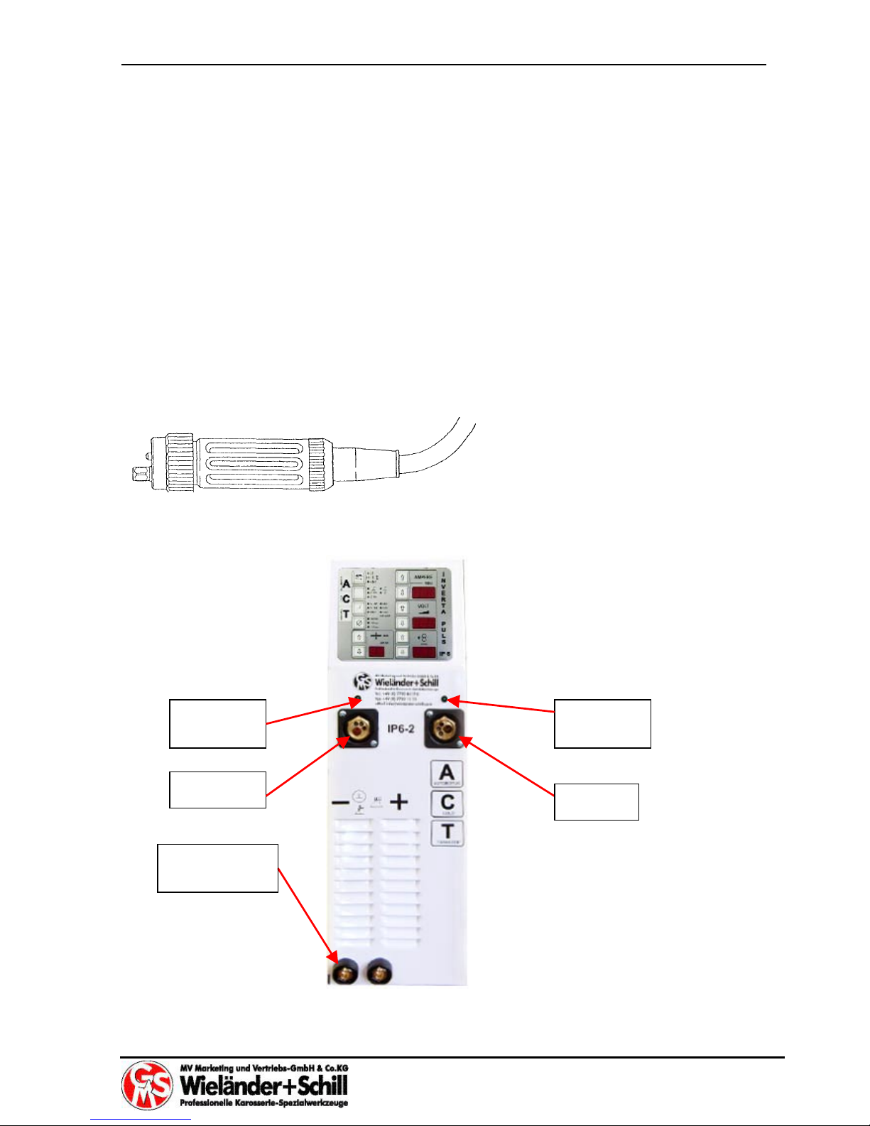
2.2 Connecting the MIG/MAG torch
For torch connecting is used EURO Standard torch connector.
Please, tighten the connector well to eliminate the conduction losses. A loose connection
can cause damage of the machine and torch.
Work piece
clamp
Torch A
Torch B
Torch B
state LED
Torch A
state LED
Inverta Puls IP6-2 ACT Operation manual
Page 6 of 20
Never use damaged torch!
Make sure the contact tip match the manufacturer’s recommendations for type and diameter
of used wire. Connect the welding conduction main connecting plug into the main socket on
the front side. Secure it with the lock nut.
In case Teflon liner is used is it necessary to use contact neck liner out of brass to provide
good current conduction to the fill wire.
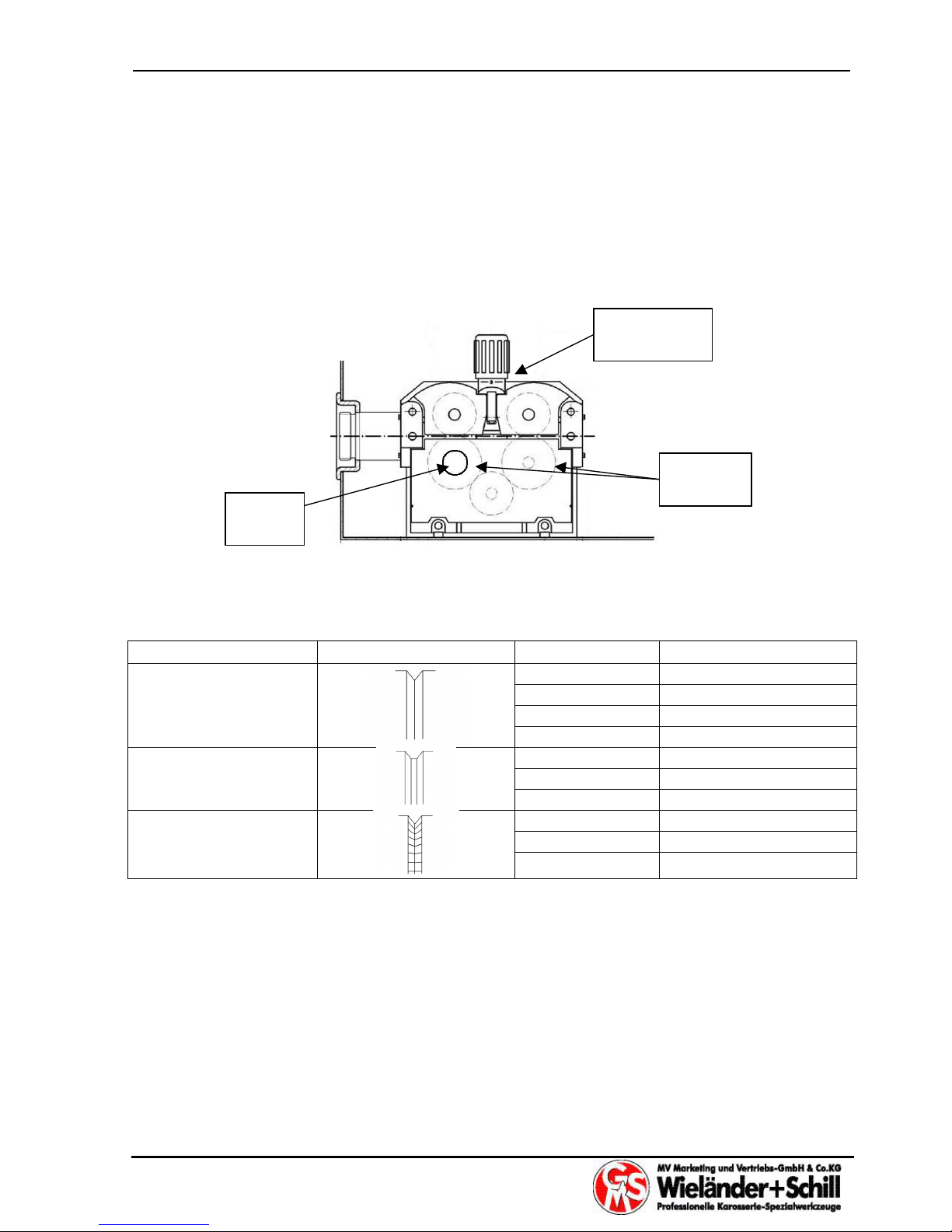
2.3 Selecting the feeding wheel
Please choose the feeding rolls correspond to used welding wire.
Materials Shape
φ
Ordering Nr.
0.6/0.8mm E017100008
0.8/1.0mm E017100015
1.0/1.2mm E017100018
Fe, SS, CuSi, CuAl
1.2/1.6mm E017100009
1.0/1.2mm E017100010
1.2/1.6mm E017100017
CuSi, CuAl, Al
1.6/2.4mm E017100011
1.0/1.2mm E017100055
1.2/1.6mm E017100056
Fe, MC, FC
When the feeding wheel is set up, you can see on the front side of wheel the assigned
welding wire diameter (value is in mm).
2.4 Connecting the pressure bottle containing protective gas
Make sure You are using right gas according welded material (see part 3.3.5)
Set the pressure bottle to the stand intended for it and fasten it by belt to the holder on the
back side of the device. Open a cover and after that open the bottle valve for a short time in
order that the gas flows away from your body. Screw a reduction valve on the pressure
Pressure
adjustment
Feeding
rolls
Fixing
point
 Loading...