

Page 1

wienet XR5i v2
LAN-toLAN VPN-Router
USER'S GUIDE
Dok.-Nr. BA000818
Stand: 01/2012 (Rev. A)
Page 2

2
Wieland Electric | BA000818 | 01/2012 (Rev. A)
This work is copyright. The resulting rights remain with the company Wieland Electric Inc.
Any duplication of this document or parts thereof is permitted only within the limits of the
statutory provisions of the Copyright Act. Alteration or abridgement of without the express
written consent of Wieland Electric GmbH.
wienet is a trademark of Wieland Electric. Other names may in this assembly manual mentioned product and brand- trademarks or registered trademarks of their respective owners
could be used, whose use by third parties for their own purposes could violate the rights of
the owners.
Page 3

Wieland Electric | BA000818 | 01/2012 (Rev. A)
3
Page 4

Contents
4
Wieland Electric | BA000818 | 01/2012 (Rev. A)
Contents
1 About this docoment........................................................................................ 5
1.1 Function of this document .......................................................................................... 5
1.1 Scope and revision levelel ........................................................................................... 5
1.2 Target group ................................................................................................................ 5
1.3 Function and design of this installation manual.......................................................... 5
1.4 Symbols and notations................................................................................................ 6
2 Safety instructions ........................................................................................... 7
2.1 Qualified persons......................................................................................................... 7
2.2 Intended Use ............................................................................................................... 7
3 Router description ............................................................................................ 8
3.1 Introduction ................................................................................................................. 8
4 Contents of package ........................................................................................ 9
5 Routerdesign .................................................................................................. 10
5.1 Version....................................................................................................................... 10
5.2 Ordering Code ........................................................................................................... 10
5.3 Basic dimensions plastic box .................................................................................... 14
5.4 Basic dimensions aluminium box.............................................................................. 15
5.5 Mechanical external dimensions and mounting recommendations .............................. 15
5.6 User interfaces (connectors) ..................................................................................... 17
5.6.1 Status indication........................................................................................................ 18
5.6.2 Power connector PWR .............................................................................................. 19
5.6.3 Ethernet Port.............................................................................................................. 20
5.6.4 PORT1........................................................................................................................ 22
5.6.5 USB port .................................................................................................................... 22
5.6.6 I/O port....................................................................................................................... 23
5.6.7 Reset.......................................................................................................................... 24
6 First use.......................................................................................................... 25
6.1 Connecting the router before first use ...................................................................... 25
6.2 Start router ................................................................................................................ 26
6.3 Router configuration.................................................................................................. 26
6.3.1 Configuration over Web browser .............................................................................. 26
6.3.2 Configuration over Telnet .......................................................................................... 26
7 Technical parameters ..................................................................................... 27
7.1 Technical parameters of router ................................................................................. 27
7.2 Technical parameters of processor ........................................................................... 27
7.3 Technical parameters of I/O port ............................................................................... 27
7.4 Technical parameters of expansion port ................................................................... 27
8 Recommended literature ................................................................................ 28
9 Possible problems .......................................................................................... 29
10 FAQ ................................................................................................................ 30
11 Customers support......................................................................................... 31
12 List of figures ................................................................................................. 32
13 List of tables................................................................................................... 33
Page 5

About this docoment
Wieland Electric | BA000818 | 01/2012 (Rev. A)
1 About this docoment
Please read this chapter carefully before working with this users guide and the wienet
mobile router
1.1 Function of this document
In this wienet LAN-toLAN router User's Guide the device and the functions of it are described. Use the User's Guide, especially for the configuring of the mobile router.
1.1 Scope and revision levelel
This installation manual is valid for the product wienet LAN-to-LAN router, which are associated with this installation manual. The installation instructions accompanying the product
is downloadable in the electronic catalog of Wieland. Be sure to always use the information provided in the current version of this installation manual. The version and revision level
can be seen in the title page and the footer.
1.2 Target group
This manual is aimed at planners, engineers, installers and service personnel who are
planning a remote control or remote maintenance solution and put into operation.
1.3 Function and design of this installation manual
This installation manual guide the technical staff of router installer on installation, programming, operation and diagnosis of wienet router.
Chapter "Safety instructions" on side 7 contain basic safety instructions. Please read and
follow these instructions in each case.
You can also use our Internet site at http://eshop.wieland-
electric.com/catalog/de_*/Wieland-de/Netzwerktechnik%20$2F%20Feldbussysteme. You
can also download the following files:
Product informations wienet router and switches
Data sheets wienet router
Technical notes WIE-SERVICE24.com VPN Server portal
NOTICE
Page 6
About this docoment
6
Wieland Electric | BA000818 | 01/2012 (Rev. A)
1.4 Symbols and notations
The symbol "DANGER" means an imminent danger. If it is not avoided, can result in death
or serious injury.
"DANGER" is used to warn of dangers at the time of the warning are already existing (eg
hot surfaces, sharp edges, pinch points, etc.).
It is used exclusively in danger of personal injury!
The symbol "WARNING" indicates a possible threat. If it is not avoided, can result in death
or serious injury could result.
The symbol "CAUTION" indicates a possible threat. If it is not avoided, slight or minor injury can result.
Refer to notes for special features of a device.
Instructions also tell you about a potentially harmful situation. If it is not avoided, the system can be damaged or something in their environment.
DANGER
WARNING
CAUTION
NOTICE
Page 7

Safety instructions
Wieland Electric | BA000818 | 01/2012 (Rev. A)
7
2 Safety instructions
This chapter is for your safety and the safety of equipment operators. Please read this
chapter carefully before working with a VPN-Router.
General Safety
Personnel who makes installation, programming, makes operational or maintenance of
wienet router, must have read and understood this manual.
The personnel must be thoroughly familiar with all warnings, instructions and requirements contained in this manual.
The applicable local safety, protection and installation requirements must be observed.
The user is solely responsible for selecting the correct product and the technical design
in accordance with appropriate local regulations
2.1 Qualified persons
Wienet VPN router must be installed by competent persons only, configured in operation,
commissioned and maintained. Qualified is, who
has an appropriate technical training and
has access to the wienet VPN router installation manuals, and this has been read and
understood.
2.2 Intended Use
Please, observe the following instructions:
The router must be used in compliance with all applicable international and national laws
and in compliance with any special restrictions regulating the utilization of the router in
prescribed applications and environments.
To prevent possible injury to health and damage to appliances and to ensure that all the
relevant provisions have been complied with, use only the original accessories. Unauthorised modifications or utilization of accessories that have not been approved may result
in damage to the router and in a breach of applicable regulations. Unauthorized modifications or utilization of accessories that have not been approved may result in the termination of the validity of the guarantee.
The router can not be opened.
Voltage at the feed connector of the router must not be exceeded.
Do not expose the router to extreme ambient conditions. Protect the router against dust,
moisture and high temperature.
The router should not be used at petrol stations. We remind the users of the duty to
observe the restrictions concerning the utilization of radio devices at petrol stations, in
chemical plants, or in the course of blasting works in which explosives are used.
Switch off the router when travelling by plane. Utilization of the router in a plane may
endanger the operation of the plane or interfere with the mobile telephone network, and
may be unlawful. Failure to observe these instructions may result in the suspension or
cancellation of telephone services for the respective client, or, it may result in legal sanctions; it may also result in both eventualities.
When using the router in the close proximity of personal medical devices, such as car-
diac pacemakers or hearing aids, you must proceed with heightened caution.
If it is in the proximity of TV sets, radio receivers and personal computers, the telephone
may cause interference.
It is recommended that you should create an appropriate copy or backup of all the im-
portant settings that are stored in the memory of the device
For any other use, or changes to the equipment - even in the context of mounting and
installation - any warranty claim against Wieland Electric Gmb expired.
WARNING
Page 8

Router description
8
Wieland Electric | BA000818 | 01/2012 (Rev. A)
3 Router description
3.1 Introduction
Industrial router
wienet
XR5i v2 is used to a secure connection of two local networks
(LAN) via two Ethernet interfaces 10/100. Connection is secured by use tunnels IPSec,
OpenVPN or L2TP. The other use of
wienet
XR5i v2 is converter from serial line RS232,
RS485, M-BUS... to IP local area network (LAN EHTERNET 100/10).
As standard features, the industrial router
wienet
XR5i v2 includes one Ethernet port
10/100, one USB host port the I/O port. The wide range of interface options on the industrial router further expands two optional ports selected by the customer – for example
Ethernet port 10/100, serial interface ports RS232/RS485/RS422/MBUS or (I/O) ports. The
industrial router is supplied either in a plastic or metal casing, based on the requirements
of the customer.
Configuration is done via web interface protected by password. The router supports creation of VPN tunnels using technologies IPsec, OpenVPN and L2TP to ensure safe communication. Web interface provides detail statistics about the router activities.
Other diagnostic functions ensuring continuous communication include automatic functionality inspection, or hardware watchdog which monitors the status of the router. With
the help of a special window (start up script window) you may insert Linux scripts for various actions. For some applications the key option to create several different configurations
for one router, the so-called profiles (maximum of 4), and the option to switch between
them (for example via binary input status, web interface, etc.) is essential.
The industrial routers
wienet
XR5i v2 may be bulk-configured within the network and also
additional software may be used - VPN server WIE-SERVICE24 or software for router
monitoring R-SeeNet.
Examples of possible applications:
security system
remote monitoring
vending and dispatcher machines
NOTICE
Page 9
Contents of package
Wieland Electric | BA000818 | 01/2012 (Rev. A)
9
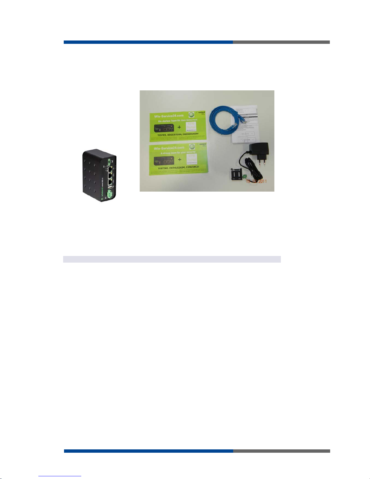
4 Contents of package
Basic deliverd set of router includes:
router
power supply
crossover UTP cable
clips for the DIN rail
assembly instruction
Notice WIE-SERVICE24
The router box and DIN mount are supplied in a metal case in the SL version of the router.
In addition to the basics it is possible to deliver:
one or two expansion ports RS232, RS485/RS422, ETHERNET, M-BUS or CNT. Separa-
tion columns for mounting expansion boards are included.
F
ig 1: contents of
package
NOTICE
Page 10
Routerdesign
10
Wieland Electric | BA000818 | 01/2012 (Rev. A)
5 Routerdesign
5.1 Version
Box I/O USB PORT1 ETH
XR5i v2 Plastic
XR5i v2 SL Metal
= Standard = optional mit Schnittstellenmodulen
Module can be connected as follows
PORT1 RS-232, RS-485/422, Ethernet, M-Bus, CNT
5.2 Ordering Code
Mobile EDGE Router wienet ER75i v2
Basic version
wienet mobile router GSM/GPRS/EDGE; Plastic or
metal housing; SIM-card-Slot; Interface: Ethernet
10/100 Mbit/s, USB 2.0 Type A Host, 1 digital input/1
digital output; Antenna connector SMA-50 Ohm;
Max. Download 236 kBit/s; Max. Upload 118,4
kBit/s; Supply voltage: DC 10-30 V; Functions:
openVPN, IPsec, DHCP (Client/Server), WebInterface, FTP, NAT, PAT, SNMP, VRRP, DynDNS,
NTP, SSH, SMS, eMail, automatic update
plastic version:
83.041.0000.0
metal version:
83.041.0000.1
Mobile EDGE Router wienet ER75i v2 CNT
Such as 83.041.0000.x
Port1: E/A module with 4x digital input (2x counter),
1x digital output, 2x analogue input
plastic version
83.041.0004.0
metal version
83.041.0004.1
Mobile EDGE Router wienet ER75i v2 ETH
Such as 83.041.0000.x
Port1: second Ethernet 10/100 MBit/s Port
plastic version
83.041.0005.0
metal version
83.041.0005.1
Mobile EDGE Router wienet ER75i v2 RS232
Such as 83.041.0000.x
Port1: serial interface RS-232
plastic version
83.041.0001.0
metal version
83.041.0001.1
Table 1: Versions
Table
2
:
Port 1 options
Table
3
:
Ordering code
Page 11
Routerdesign
Wieland Electric | BA000818 | 01/2012 (Rev. A)
11
Mobile UMTS Router wienet UR5 v2
Basic version
wienet mobile router GSM/GPRS/UMTS; Plastic or
metal housing; SIM-card-Slot; Interface: Ethernet
10/100 Mbit/s, USB 2.0 Type A Host, 1 digital input/1
digital output; Antenna connector SMA-50 Ohm;
Max. Download 3,6 MBit/s; Max. Upload 384 kBit/s;
Supply voltage: DC 10-30 V; Functions: openVPN,
IPsec, DHCP (Client/Server), Web-Interface, FTP,
NAT, PAT, SNMP, VRRP, DynDNS, NTP, SSH, SMS,
eMail, automatic update
plastic version
83.041.0020.0
metal version
83.041.0020.1
Mobile UMTS Router wienet UR5 v2 CNT
Such as 83.041.0020.x
Port1: E/A module with 4x digital input (2x counter),
1x digital output, 2x analogue input
plastic version
83.041.0024.0
metal version
83.041.0024.1
Mobile UMTS Router wienet UR5 v2 ETH
Such as 83.041.0020.x
Port1: second Ethernet 10/100 MBit/s Port
plastic version
83.041.0025.0
metal version
83.041.0025.1
Mobile UMTS Router wienet UR5 v2 RS232
Such as 83.041.0020.x
Port1: serial interface RS-232
plastic version
83.041.0021.0
metal version
83.041.0021.1
Mobile UMTS Router wienet UR5 v2 RS485/422
Such as 83.041.0020.x
Port1: serial interface RS-485/422
plastic version
83.041.0022.0
metal version
83.041.0022.1
Mobile UMTS Router wienet UR5 v2 MBus
Such as 83.041.0020.x
Port1: M-Bus interface
plastic version
83.041.0023.0
metal version
83.041.0023.1
Page 12

Routerdesign
12
Wieland Electric | BA000818 | 01/2012 (Rev. A)
Mobile HSPA+ Router wienet UR5i v2
Basic version
wienet mobile router GSM/GPRS/HSPA+; Plastic or
metal housing; SIM-card-Slot; Interface: Ethernet
10/100 Mbit/s, USB 2.0 Type A Host, 1 digital input/1
digital output; Antenna connector SMA-50 Ohm;
Max. Download 14,4 MBit/s; Max. Upload 5,7
MBit/s; Supply voltage: DC 10-30 V; Functions:
openVPN, IPsec, DHCP (Client/Server), WebInterface, FTP, NAT, PAT, SNMP, VRRP, DynDNS,
NTP, SSH, SMS, eMail, automatic update
plastic version
83.041.0040.0
metal version
83.041.0040.1
Mobile HSPA+ Router wienet UR5i v2 CNT
Such as 83.041.0040.x
Port1: E/A module with 4x digital input (2x counter),
1x digital output, 2x analogue input
plastic version
83.041.0044.0
metal version
83.041.0044.1
Mobile HSPA+ Router wienet UR5i v2 ETH
Such as 83.041.0040.x
Port1: second Ethernet 10/100 MBit/s Port
plastic version
83.041.0045.0
metal version
83.041.0045.1
Mobile HSPA+ Router wienet UR5i v2 RS232
Such as 83.041.0040.x
Port1: serial interface RS-232
plastic version
83.041.0041.0
metal version
83.041.0041.1
Mobile HSPA+ Router wienet UR5i v2 RS485/422
Such as 83.041.0040.x
Port1: serial interface RS-485/422
plastic version
83.041.0042.0
metal version
83.041.0042.1
Mobile HSPA+ Router wienet UR5i v2 MBus
Such as 83.041.0040.x
Port1: M-Bus interface
plastic version
83.041.0043.0
metal version
83.041.0043.1
Page 13

Routerdesign
Wieland Electric | BA000818 | 01/2012 (Rev. A)
13
LAN-to-LAN Router wienet XR5i v2
Basic version
wienet LAN-to-LAN router; Plastic housing; Interface:
Ethernet 10/100 Mbit/s, USB 2.0 Type A Host, 1
digital input/1 digital output; Supply voltage: DC 1030 V; Functions: openVPN, IPsec, DHCP
(Client/Server), Web-Interface, FTP, NAT, PAT,
SNMP, VRRP, DynDNS, NTP, SSH, SMS, eMail,
automatic update
plastic version
83.041.0060.0
metal version
83.041.0060.1
LAN-to-LAN Router wienet XR5i v2 CNT
Such as 83.041.0060.0
Port1: E/A module with 4x digital input (2x counter),
1x digital output, 2x analogue input
plastic version
83.041.0064.0
metal version
83.041.0064.1
LAN-to-LAN Router wienet XR5i v2 ETH
Such as 83.041.0060.0
Port1: second Ethernet 10/100 MBit/s Port
plastic version
83.041.0065.0
metal version
83.041.0065.1
LAN-to-LAN Router wienet XR5i v2 RS232
Such as 83.041.0060.0
Port1: serial interface RS-232
plastic version
83.041.0061.0
metal version
83.041.0061.1
LAN-to-LAN Router wienet XR5i v2 RS485/422
Such as 83.041.0060.0
Port1: serial interface RS-485/422
plastic version
83.041.0062.0
metal version
83.041.0062.1
LAN-to-LAN Router wienet XR5i v2 MBus
Such as 83.041.0060.0
Port1: M-Bus interface
plastic version
83.041.0063.0
metal version
83.041.0063.1
Page 14

Routerdesign
14
Wieland Electric | BA000818 | 01/2012 (Rev. A)
wienet vendor antenne GXR626
wienet vendor antenna; GSM, GPRS, EDGE, UMTS,
HSPA+; Flat antenna hight only 13 mm; with cable
2,5 m
83.041.0200.0
wienet outdoor rod antenna GXR606
wienet outdoor antenna in rod form; GSM, GPRS,
EDGE, UMTS, HSPA+; rod lenght: 300 mm; inclusive stainless steel mounting bracket; with cable 5 m
83.041.0210.0
5.3 Basic dimensions plastic box
F
ig
2
: B
asic
dimensions plastic box
Page 15

Routerdesign
Wieland Electric | BA000818 | 01/2012 (Rev. A)
15
5.4 Basic dimensions aluminium box
5.5 Mechanical external dimensions and mounting recom-
mendations
Mounting recommendations:
possibility to be put on a work surface,
DIN rail with clips CPD2 (Elpac clip SL for SL version) are included
For the most of applications with a built-in router in a switch board it is possible to recognize two kinds of environments:
no public and industry environment of low voltage with high interference,
public environment of low voltage without high interference.
For both of these environments it is possible to mount router to a switch board, the following there is no need to have examination immunity or issues in connection with EMC
according to EN 60439-1 ed.2:00 + A1:04.
for every cables we recommend to bind the bunch according to the following picture,
we recommend for this use:
length of the bunch (combination of power supply and data cables) can be maximum
1,5 m, if the length of data cables exceeds 1,5 m or in the event of, the cable leads towards the switch - board, we recommend installing over - voltage protectors (surge
suppressors),
with data cables they mustn't carry cables with reticular tension ~ 230 V/50 Hz,
all signals to sensors must be twisted pairs
Cable routing for plastic version
Cable routing for metal version
sufficient space must be left before individual connectors for handling of cables
F
ig
3
: B
asic
dimensions metal box
NOTICE
CAUTION
F
ig 4: cable routing
CAUTION
Page 16

Routerdesign
16
Wieland Electric | BA000818 | 01/2012 (Rev. A)
Space in front connectors plastic version
Space in front connectors metal version
for correct function of the router we recommend to use in the switch-board earthbonding distribution frame for grounding of power supply of router, data cables and antenna
F
ig 5: space in front
connectors
CAUTION
Page 17

Routerdesign
Wieland Electric | BA000818 | 01/2012 (Rev. A)
17
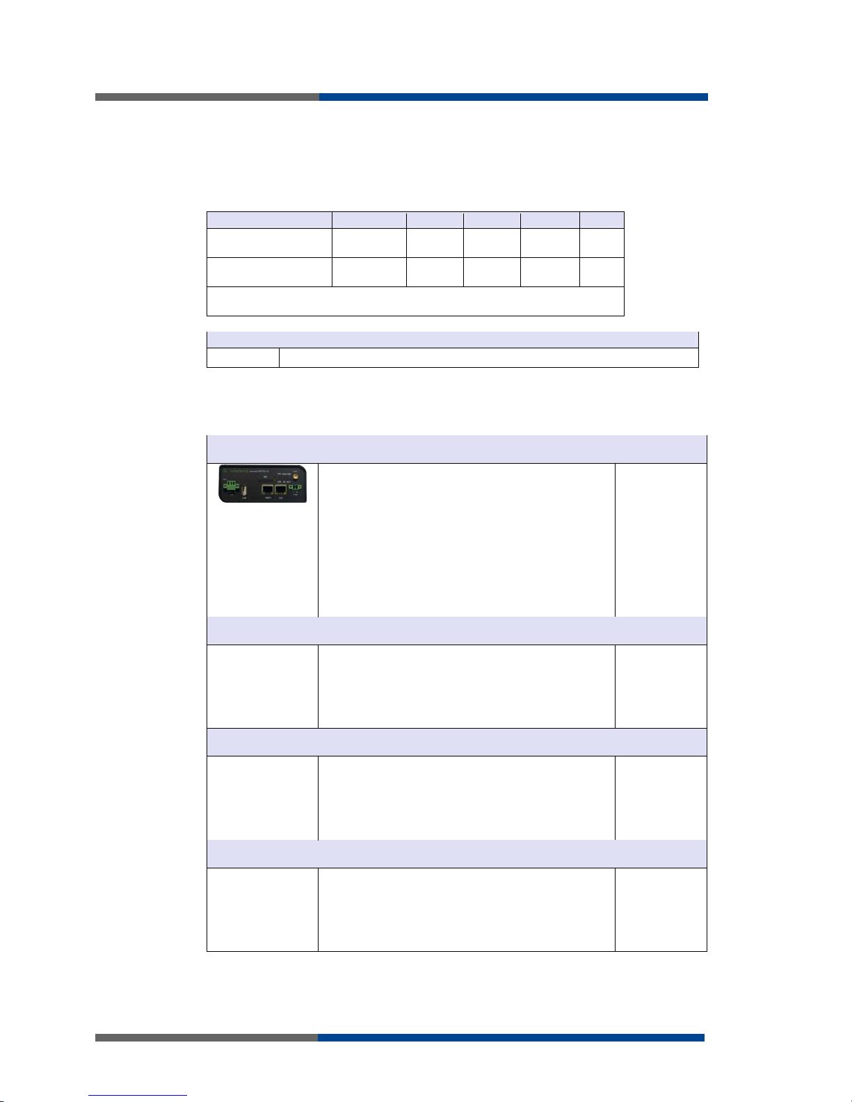
5.6 User interfaces (connectors)
On the front panel is located:
Label Connector Desciption
PWR 2-pin Connector for connection the power adapter
ETH RJ-45 Connector for connection into the local area network
Port1 RJ-45 Connector for connection into the local area network
Port2
(option)
RJ-45
Connector for connection equipment over RS-232, RS-485/422,
Ethernet, M-Bus or CNT
USB USB-A Host
Connector– for connection the devices with the router, USB
supports equipments with PL-2303 and FTDI USB/RS232 converter.
I/O 3-pin Connector for connection of the binary input and output.
Table 4: Front panel
F
i
g 6: Front panel
X
R5i
v2
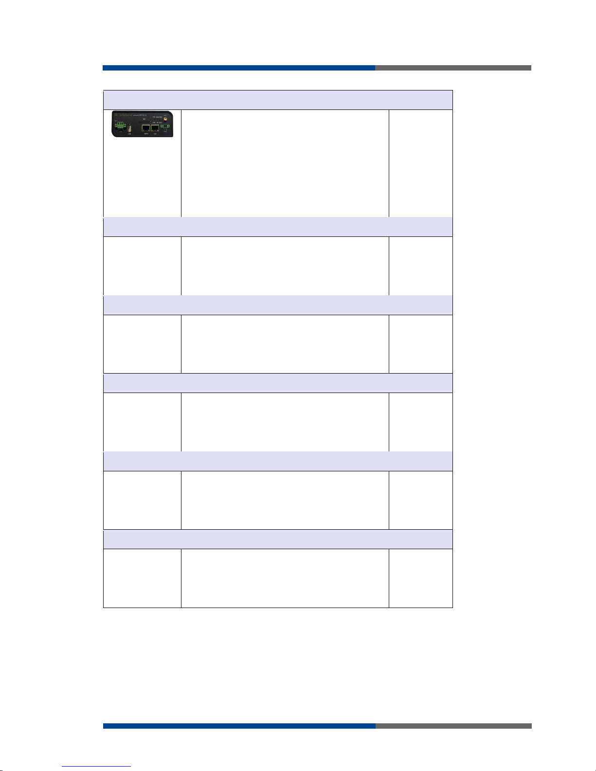
F
i
g 7: Front panel
X
R5i
v2 SL
Page 18

Routerdesign
18
Wieland Electric | BA000818 | 01/2012 (Rev. A)
5.6.1 Status indication
About router status inform four led indicators on the front panel and on every port are two
LED indicators, which inform about port status.
Panel Color Description Desciption
Front Green PWR
Blinking:
Permanently on:
Router is ready
Starting of the router
Front Geen USR Function selected by user
Front Green OUT On: Binary output active
Front Green IN On: Binary input active
Front Green ETH
On:
Off:
Selected 100 MBit/s
Selected 10 MBit/s
Front Yellow ETH
On:
Blinking:
Off:
Network cable is connected
Data transmission
Network cable is not connected
Front Green PORT Description by Port (viz. Technical specification)
Front Yellow PORT Description by Port (viz. Technical specification)
Table 5: Status
indication
Page 19

Routerdesign
Wieland Electric | BA000818 | 01/2012 (Rev. A)
19
5.6.2 Power connector PWR
Panel socket 2-pin
Pin
number
Signal
mark
Desciption
1 VCC (+) Positive pole of DC supply voltage (+10 to +30 VDC)
2 GND (-) Negative pole of DC supply voltage
Power supply for router is required between +10 V to +30 V DC supply. Protection against
reversed polarity without signaling is built into the router.
The power consumption during receiving is 1W. The peak power consumption during data
sending is 5,5W. For correct operation it is necessary that the power source is able to supply a peak current of 600mA.
Connector on the power cable connects into the power connector on the router head and
tightens locking screws. (See bellow picture)
Circuit example:
The positive pole VCC is marked by a red socket on the power.
Table
6
:
Po
w
e
r
connector
F
ig
8
: P
ower connecto
r
NOTICE
F
ig 9: connection of
power supply
connector
F
ig 10: connection of
power supply
NOTICE
Page 20

Routerdesign
20
Wieland Electric | BA000818 | 01/2012 (Rev. A)
5.6.3 Ethernet Port
Panel socket RJ45
Pin
number
Signal
mark
Desciption Data flow direction
1 TXD (+) Transmit Data - positive pole Input/Output
2 TXD (-) Transmit Data - negative pole Input/Output
3 RXD (+) Receive Data - positive pole Input/Output
4 --- ---
5 --- ---
6 RXD (-) Receive Data - negative pole Input/Output
7 --- ---
8 --- ---
ATTENTION! Port ETH is not POE (Power Over Ethernet) compatible!
Table 7: Ethernet port
F
ig 11: Ethernet
connector
CAUTION
Page 21

Routerdesign
Wieland Electric | BA000818 | 01/2012 (Rev. A)
21
Ethernet cable plug into the RJ45 connector labeled as ETH. (See bellow picture)
The Ethernet router connection:
NOTICE
F
ig 12: connection
Ethernet cable
F
ig 13: example of
router connection
Page 22

Routerdesign
22
Wieland Electric | BA000818 | 01/2012 (Rev. A)
5.6.4 PORT1
The PORT1 is equipped with one of the offered options ports. For PORT1 are available on
the interface.
PORT1 RS-232, RS-485/422, ETHERNET, M-BUS, CNT
Description, connection and examples of optional connection ports can be found in separate manuals expansion ports.
PORT1 cable plug into the RJ45 connector labeled as ETH. (See bellow picture)
5.6.5 USB port
Panel socket USB-A.
Pin
number
Signal mark Desciption Data flow direction
1 +5V Positive pole of 5V DC supply voltage
2 USB data - USB data signal - negative pole Input/Output
3 USB data + USB data signal - positive pole Input/Output
4 GND Negative pole of 5V DC supply voltage
Example of connecting devices with serial interface to the USB router:
NOTICE
F
ig 14: connec
t
i
on
PORT1 cable
Table
8
:
USB port
F
ig 15: USB connector
NOTICE
F
ig 1
6
:
connection PLC
to the router
Page 23

Routerdesign
Wieland Electric | BA000818 | 01/2012 (Rev. A)
23
Example of connecting of USB flash disk to the USB router:
5.6.6 I/O port
Panel socket 3pin
Pin
number
Signal mark Desciption Data flow direction
1 BIN0 Binary input Input
2 GND Signal ground
3 OUT0 Binary output Output
The user interface I/O is for processing of binary input signal and to control (settings) of
binary output signal. Binary output is not switched to ground, by default configuration.
Maximum load binary output is 30V / 100mA. The constant current supplied by the binary
input is 3 mA.
Connector I/O cable connect into the I/O connector on the router head and tighten locking
screws. (See bellow picture)
Circuit example of a binary input or output equipment with router:
F
ig 17: connection
flash memory to the
router
Table 9
:
I/O por
t
F
ig 1
8
: I
/O connecto
r
NOTICE
F
ig 19: Connection I/O
cable
NOTICE
F
ig 20: Connection
input and output of
router
Page 24

Routerdesign
24
Wieland Electric | BA000818 | 01/2012 (Rev. A)
5.6.7 Reset
It is important to distinguish between reset and reboot the router.
Action Router behavior Invoking events
Disconnect and connect the power Reboot Turn off and then tur on router
Press the reboot button in the web
configuration
Reset
Restore default configuration and to
reboot the router.
Press RST button
After green LED starts to blink it is possible to restore initial settings of the router by pressing button RST on front panel. After press button RST it is restoration of factory configuration and reboot (green LED will be on).
For pressing the RST button could be used a narrow screwdriver.
We recommend to backup your router configuration (See configuration guide), because
reset router set configuration to the initial state.
NOTICE
Table 10: Reset/Reboot
NOTICE
F
ig 21: Router reset
NOTICE
Page 25

First use
Wieland Electric | BA000818 | 01/2012 (Rev. A)
25
6 First use
6.1 Connecting the router before first use
Before you give up the router, it is necessary to connect all components needed for the
operation of your applications (See bellow picture).
F
ig 22: Router
connection
Page 26

First use
26
Wieland Electric | BA000818 | 01/2012 (Rev. A)
6.2 Start router
The router is set up connecting the power supply to the router. Device on the Ethernet port
DHCP server will assign addresses. The behavior of the router can be modified by means
of the web or Telnet interface, which is described in the configuration manual.
The power consumption during receiving is 1W. The peak power consumption during data
sending is 5,5W. For correct operation it is necessary that the power source is able to supply a peak current of 600mA.
6.3 Router configuration
6.3.1 Configuration over Web browser
Monitoring of the status, configuration and administration of the router can be performed
by means of the web interface, which is available after insertion of IP address of the router
into the web browser. The default IP address of the router is 192.168.1.1. Configuration
may be performed only by the user "root" with initial password "root".
A detailed description of the router settings via the Web interface can be found in the configuration guide.
6.3.2 Configuration over Telnet
Monitoring of status, configuration and administration of the router can be performed by
means of the Telnet interface. After IP address entry to the Telnet interface it is possible to
configure the router by the help of commands. The default IP address of the router is
192.168.1.1. Configuration may be performed only by the user "root" with initial password
"root".
A detailed description of the router settings via the Telnet interface can be found in the
configuration guide.
NOTICE
NOTICE
Page 27

Technical parameters
Wieland Electric | BA000818 | 01/2012 (Rev. A)
27
7 Technical parameters
7.1 Technical parameters of router
wienet XR5i v2
Complies with standards EN ETSI 301 489-1 V1.9.1
EN 60950-1:06 ed.2 + A11:09 + A1:10
Temperature range Operation
Storage
-30 °C to +60 °C
-40 °C to +85 °C
Protection rating Freely
In switch board
IP20
IP56
Supply voltage +10 V DC to +30 V DC
Consumption Reception 300 mW
Dimensions 42x76x113 mm (DIN 35 mm)
Weight XR5i v2 - 150 g
XR5i v2 SL - 280 g
User interface ETH and Port 1
USB
PORT2
Ethernet 10/100 MBit/s
USB 2.0 type A host
Optional RS-232, RS-485/422, ETHERNET, M-BUS or
inputs/outputs (CNT)
7.2 Technical parameters of processor
32b ARM microprocessor
Memory 512 Mb DDR SDRAM
128 Mb FLASH
1 Mb MRAM
Interface Serial interface RS-232
Ethernet interface 10/100Mbit/s
USB 2.0 interface
7.3 Technical parameters of I/O port
I/O Port
Binary Input Reed contact
with trigger level 1,3 to
1,4 V
Input/Output
Binary output 120 mA / max. 30 V
7.4 Technical parameters of expansion port
Technical parameters of the expansion ports are to be found in separate manuals for expansion ports.
Table 11: Technical
parameters router
Table 12
:
Technical
parameters of
processor
Table 13
:
Technical
parameters I/O port
Page 28

Recommended literature
28
Wieland Electric | BA000818 | 01/2012 (Rev. A)
8 Recommended literature
[1] Wieland: Start guide,
[2] Wieland: Configuration manual VPN-Router,
[3] Wieland: Technical note WIE-SERVICE24 VPN Portal configuration
Page 29

Possible problems
Wieland Electric | BA000818 | 01/2012 (Rev. A)
29
9 Possible problems
Some network cards are able to be set in situation, when it is not possible to connect the
router. It is possible to solve this problem in the following steps:
hand by selection communication rates 10 MB/s in property network cards,
connect router over switch,
start computer only after finalizing the start of the router.
NOTICE
Page 30

FAQ
30
Wieland Electric | BA000818 | 01/2012 (Rev. A)
10 FAQ
I can’t get from internet on equipment, which is connected to router and I have NAT
enabled.
The device's gateway has to be configured as the router.
Router resets itself, connection on Ethernet fails.
It is necessary to use an antenna, which will be situated far from power supply.
I don’t get on web server at NAT.
The remote http access of the router has to be disabled, default server address has to
be your web server and the gateway of the web server has to be the IP of router.
Connection fails on Ethernet or connection isn’t establishing.
On ethernet interface of the router it is possible to switch auto negotiation off and set
a rate and duplex by hand.
DynDNS not function.
In private APN not functional.
If the same IP address is recorded in your canonic name as dynamically assign address, it means that the operator is using NAT or firewall.
NAT is possible to verify by the help of the ping on address of your server with static
IP address and by the help of the router address verify and address in ping.
Firewall is possible to verify, for example by remote access on web interface.
The operator doesn’t give out address DNS servers and without DNS server’s it is impossible to connect to server dyndns.org. In log system will be this message:
o DynDNS daemon started,
o Error resolving hostname: no such file or directory,
o Connect to DynDNS server failed.
IPSec tunnel is establishing but communication doesn’t function.
Probably it is badly set up route conditionals of connected equipment or it is bad set
up GW.
FTP doesn’t function.
Router doesn’t support the active FTP mode, supports the passive mode only.
RS232 doesn’t function.
It is necessary to verify present the expansion port RS232.
Verify present the expansion port RS232 in router configuration in menu „external
port“, or verify connection locally by the help Telnet-Hyper terminal.
L2TP or IPSec isn’t establishing.
Verify the reason in the log system.
Page 31

Customers support
Wieland Electric | BA000818 | 01/2012 (Rev. A)
31
11 Customers support
Up to date information about the product is on website:
http://www.wieland-electric.com/
http://eshop.wieland-electric.com/
Upkeep-advices:
Admission:
Wieland Electric hereby declares that the router narrated in this user’s guide fits all basic
demands of directive 1999/5/EC (R&TTE).
Page 32

List of figures
32
Wieland Electric | BA000818 | 01/2012 (Rev. A)
12 List of figures
Fig 1: contents of package ..................................................................................................... 9
Fig 2: Basic dimensions plastic box ..................................................................................... 14
Fig 3: Basic dimensions metal box....................................................................................... 15
Fig 4: cable routing............................................................................................................... 15
Fig 5: space in front connectors........................................................................................... 16
Fig 6: Front panel XR5i v2 .................................................................................................... 17
Fig 7: Front panel XR5i v2 SL ............................................................................................... 17
Fig 8: Power connector ........................................................................................................ 19
Fig 9: connection of power supply connector...................................................................... 19
Fig 10: connection of power supply..................................................................................... 19
Fig 11: Ethernet connector ................................................................................................... 20
Fig 12: connection Ethernet cable........................................................................................ 21
Fig 13: example of router connection .................................................................................. 21
Fig 14: connection PORT1 cable .......................................................................................... 22
Fig 15: USB connector ......................................................................................................... 22
Fig 16: connection PLC to the router ................................................................................... 22
Fig 17: connection flash memory to the router.................................................................... 23
Fig 18: I/O connector ............................................................................................................ 23
Fig 19: Connection I/O cable ................................................................................................ 23
Fig 20: Connection input and output of router..................................................................... 23
Fig 21: Router reset .............................................................................................................. 24
Fig 22: Router connection .................................................................................................... 25
Page 33

List of tables
Wieland Electric | BA000818 | 01/2012 (Rev. A)
33
13 List of tables
Table 1: Versions ...................................................................................................................10
Table 2: Port 1 options ..........................................................................................................10
Table 3: Ordering code..........................................................................................................10
Table 4: Front panel ..............................................................................................................17
Table 5: Status indication......................................................................................................18
Table 6: Power connector .....................................................................................................19
Table 7: Ethernet port............................................................................................................20
Table 8: USB port ..................................................................................................................22
Table 9: I/O port.....................................................................................................................23
Table 10: Reset/Reboot .........................................................................................................24
Table 11: Technical parameters router..................................................................................27
Table 12: Technical parameters of processor .......................................................................27
Table 13: Technical parameters I/O port ...............................................................................27
Page 34

Wieland Electric | BA000818 | 01/2012 (Rev. A)
 Loading...