

Page 1

wienet LMS 16-W
Ethernet switch
USER MANUAL
Doc.-No. BA001108
Updatet:01/2017 (Rev. A)
Page 2

COPYRIGHT
NOTE
Note!
The exact scope of delivery is described in the respective purchase contract.
AT.TS@wieland-electric.com
http://www.wieland-electric.com
This document is copyright-protected. The rights derived from this copyright
are reserved for Wieland Electric GmbH. Reproduction of this document or
parts of this document is only permissible within the limits of the statutory provision of the Copyright Act. Any modification or abridgment of the document is
prohibited without the express written agreement of Wieland Electric GmbH.
Any other product or trade names listed in these operating instructions are the
trademarks or registered trademarks of the respective owners.
Every effort has been made to ensure that the information contained in this
document was complete and accurate at the time of publishing. Nevertheless,
the authors retain the right to modify the information. This customer document
describes all the hardware units and functions known at the present time. Descriptions may be included for units which are not present at the customer site.
Conformity
Information
Technical support
Adress
For more information regarding CE marking and Declaration of Conformity
(DoC), please contact your local Wieland Electric customer service organization.
Up-to-date information concerning the product is available from the following
websites:
http://www.wieland-electric.com/
http://eshop.wieland-electric.com/
Technical support
Industrial Automation -Electronics
Hotline:
+49 (0) 951 / 93 24-995
E-Mail:
Wieland Electric GmbH
Brennerstraße 10-14
96052 Bamberg
Phone: +49 (0) 9 51 93 24-0
Fax: +49 (0) 9 51 93 24-198
E-mail: info@wieland-electric.com
http://eshop.wieland-electric.com
2 Wieland Electric GmbH | BA001108 (Rev. A) | 01/2017
Page 3

1 | About this manual
1 About this manual ........................................................................................ 4
1.1 Target groups and qualification of personnel......................................................... 4
1.2 Structure of the manual ......................................................................................... 4
1.3 Presentation of safety-relevant information ........................................................... 4
2 Product Disposal Instructions ...................................................................... 5
3 Switch description ........................................................................................ 6
3.1 High-Speed Transmissions ..................................................................................... 6
3.2 Dual Power Input.................................................................................................... 6
3.3 Flexible Mounting ................................................................................................... 6
3.4 Advanced Protection .............................................................................................. 6
3.5 Wide Operating Temperature ................................................................................. 6
3.6 Easy Troubleshooting ............................................................................................. 7
3.7 Features .................................................................................................................. 7
4 Contents of Package .................................................................................... 7
5 Switch Design .............................................................................................. 8
5.1 Basic dimensions of the switch.............................................................................. 8
5.2 Ordering code ......................................................................................................... 8
5.3 Mounting and demounting recommendations ...................................................... 9
5.4 Mounting and demounting on a DIN rail ............................................................... 9
5.5 Mounting on a wall .............................................................................................. 10
5.6 Description of the Front-Panel ............................................................................. 11
5.6.1 Ethernet Port (ETH0 to ETH16) ................................................................. 12
5.6.2 Network connection ................................................................................. 12
5.7 Power connection and wiring .............................................................................. 13
5.7.1 Grounding the device ............................................................................... 13
5.7.2 Overview................................................................................................... 13
5.7.3 Wiring the power outputs ........................................................................ 14
6 Technical Parameters ................................................................................. 14
6.1 Basic parameters .................................................................................................. 14
6.2 Standards and regulations ................................................................................... 15
7 Troubleshooting ......................................................................................... 16
7.1 Diagnosis with LED Indicators ............................................................................. 16
7.2 FAQ troubleshooting ............................................................................................ 16
8 Recommended Literature ........................................................................... 16
Wieland Electric GmbH | BA001108 (Rev. A) | 01/2017 3
Page 4
DANGER
ATTENTION
NOTE!
1 About this manual
Please read this section carefully before you use this manual and the
you will find all the information required for commissioning and operation.
wienet
Switch from Wieland. Here
1.1 Target groups and qualification of personnel
Commissioning and installation of components for such types of installations must be considered.
Therefore, the system manual is targeted at the following:
• Those who can verify that they have the corresponding training and already have corresponding basic
knowledge
• System integrators
• Electricians
1.2 Structure of the manual
As a guidance the overall table of contents is available in the manual at the beginning.
1.3 Presentation of safety-relevant information
Information that warns of personal injury or property damage are emphasized by safety instructions.
Please read this information carefully.
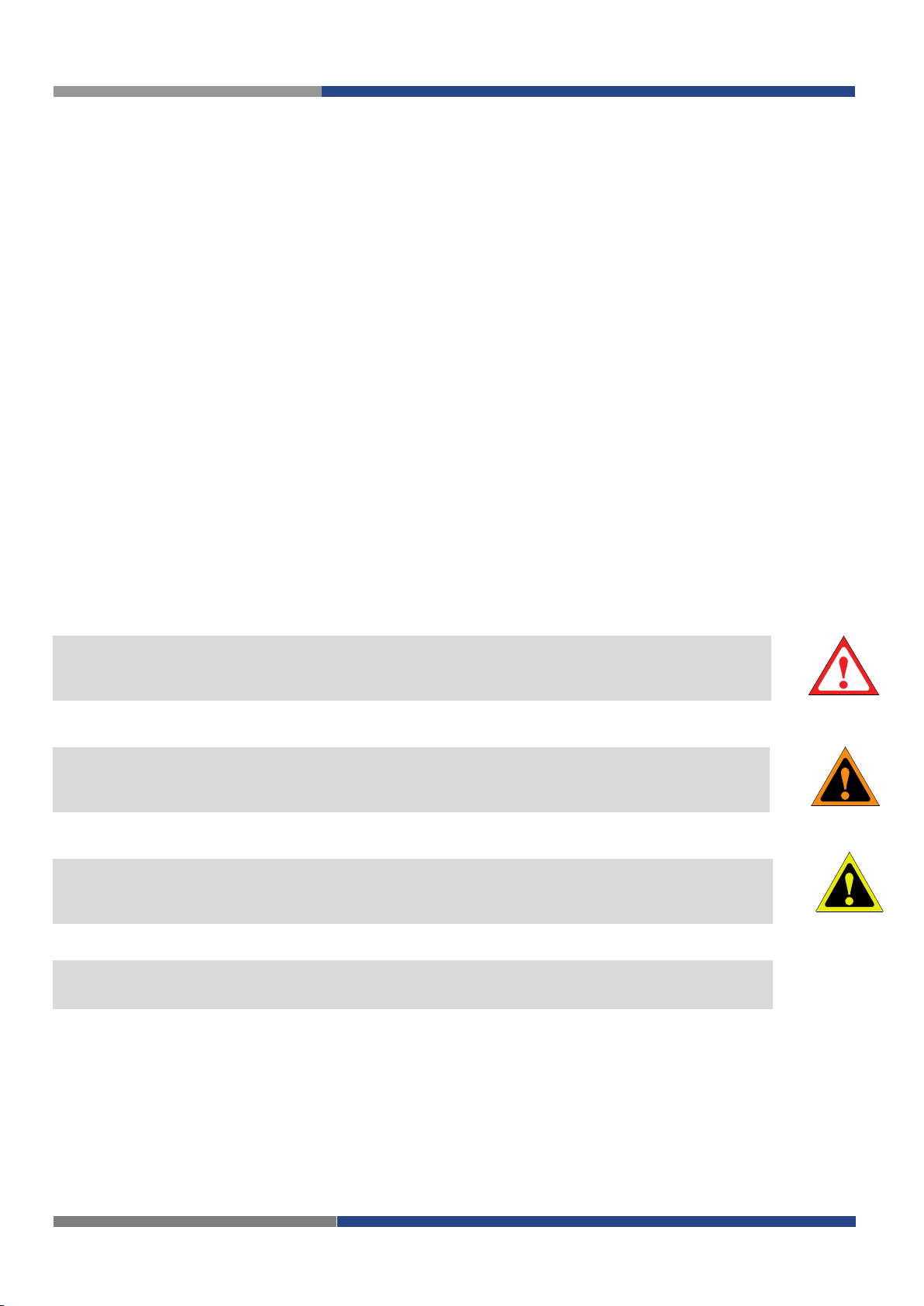
This operating manual uses various safety notices that are assigned according to the severity of a potential hazard:
Danger!
Immediate or likely danger. Personal injury or death is possible.
Warning!
Possible danger. Not heeding this warning can lead to minor injuries.
Attention!
Damages to property is likely if these warnings are not heeded.
Note!
Supplementary information and useful tips, indirectly related to the safety of personnel or property.
"Danger" or "Warning" are strictly used for cases which present a risk to life or limb. Damage to property
only falls into these categories if there is also a risk of personal injury that corresponds to these levels.
WARNING
4 Wieland Electric GmbH | BA001108 (Rev. A) | 01/2017
Page 5

Please, observe the following instructions:
ATTENTION
Attention!
• The switch must be used in compliance with all applicable international and national laws
and in compliance with any special restrictions regulating the utilization of the switch in prescribed applications and environments.
• To prevent possible injury to health and damage to appliances and to ensure that all the rele-
vant provisions have been complied with, use only the original accessories.
• Unauthorised modifications or utilization of accessories that have not been approved may
result in damage to the switch and in a breach of applicable regulations. Unauthorized modifications or utilization of accessories that have not been approved may result in the termination of the validity of the guarantee.
• The switch can not be opened.
• Disconnect power before making any configuration changes.
• If DC voltage is supplied by an external circuit, a protection device on the Power supply input
is recommended.
Warning!
• The voltage must not be exceeded by 48 V DC max.at the power connector on the switch.
WARNING
• Do not expose the switch to extreme ambient conditions. Protect the switch against dust,
moisture and high temperature.
• The switch should not be used at petrol stations of flammable and explosive materials. We
remind the users of the duty to observe the restrictions concerning the utilization of radio devices at petrol stations, in chemical plants, or in the course of blasting works in which explosives are used.
• Switch off the switch when travelling by plane. Utilization of the switch in a plane may en-
danger the operation of the plane or interfere with the mobile telephone network, and may
be unlawful. Failure to observe these instructions may result in the suspension or cancellation of telephone services for the respective client, or, it may result in legal sanctions; it may
also result in both eventualities.
• When using the switch in the close proximity of personal medical devices, such as cardiac
pacemakers or hearing aids, you must proceed with heightened caution.
• If it is in the proximity of TV sets, radio receivers and personal computers, the telephone may
cause interference.
• It is recommended that you should create an appropriate copy or backup of all the important
settings that are stored in the memory of the device.
2 | Product Disposal Instructions
2 Product Disposal Instructions
The WEEE (Waste Electrical and Electronic Equipment: 2012/19/EU) directive has been introduced to ensure that electrical/electronic products are recycled using the best available recovery techniques to minimize the impact on the environament. This product contains high quality materials and components
which can be recycled. At the end of it’s life this product MUST NOT be mixed with other commercial
waste for disposal. Check the terms and conditions of your supplier for disposal information.
Wieland Electric GmbH | BA001108 (Rev. A) | 01/2017 5
Page 6

V
2-
V
2+
11
1
4
P
2 P
1
V1
-
V
1
+
P-
F
ai
l
Lo
o
p
3 Switch description
The 16 port 10/100-TX with 4 Port High-Power PoE Industrial Switch is a cost-effective solution, which
meets the high reliability requirements demanded by industrial applications, and also supports to operate
V DC
in the wide temperature range from -40°C to 75°C. The equipment supports 12 V to 48
and provides the PoE function with 48
as data over an RJ-45 cable.
V DC output for kinds of Powered Devices to receive power as well
power input
Block diagram
3.1 High-Speed Transmissions
The
wienet
(10/100 Mbps). The RJ-45 interface can also be auto-detected, so MDI or MDI-X is automatically selected
and a crossover cable is not required. All Ethernet ports have memory buffers that support the store-andforward mechanism. This assures that data is properly transmitted.
LMS 16-W includes a switch controller that can automatically sense transmission speeds
3.2 Dual Power Input
wienet
device broken by wrong power wiring. When one of the power inputs fails, P-Fail LED will turn on and
send an alarm through a relay output for notifying the user.
LMS 16-W redundant power input design is with power reserve protection to prevent the switch
3.3 Flexible Mounting
wienet
any space-constrained environment.
LMS 16-W is extremely compact and can be mounted on a DIN-rail or a panel, so it is suitable for
3.4 Advanced Protection
wienet
6,000 V ESD for Ethernet ports. With these two strong protections, it can secure equipment against unregulated voltage and make systems safer and more reliable. Further,
load protection with a resettable fuse to ensure that the device component won’t be damaged by overload
current.
LMS 16-W supports up to 3,000 V DC surge protection for power line, and also supports
wienet
LMS 16-W provides currency over-
3.5 Wide Operating Temperature
The operating temperature of the
can use the
6 Wieland Electric GmbH | BA001108 (Rev. A) | 01/2017
wienet
LMS 16-W in some of the harshest industrial environments that exist.
wienet
LMS 16-W is between -40 ~ 75 ℃. With such a wide range, you
Page 7

4 | Contents of Package
3.6 Easy Troubleshooting
LED indicators make troubleshooting quick and easy. Each 10/100 Base-TX port has 2 LEDs that display
the link status, transmission speed and collision status. Also the three power indicators P1, P2, P-Fail and
Loop help you diagnose immediately.
3.7 Features
• Provides 16 x 10/100Base-TX ethernet ports with 4 PoE injectors of RJ-45 connector
• Supports +12 to 48
• Provides flexible mounting: DIN-rail, wall mounting
• Supports operating temperature from -40 ~ 75 ℃
V DC power input
4 Contents of Package
• 1 x
wienet
• 1 x Wall mounting bracket and screws
• 1 x DIN-rail mounting bracket and screws (preassembled)
• 1 x Installation instructions
LMS 16-W Industrial Ethernet Switch
Wieland Electric GmbH | BA001108 (Rev. A) | 01/2017 7
Page 8

Name
Order code
Features – interfaces
LMS 16-W
83.040.1334.0
16x ETH 10/100 TX
wieland
w
LMS 16
P
1
P
2
P
-
Fai
l
Lo
o
p
1 5
2 6
3 7
4 8
9 13
10 14
11 15
12 16
wienet
74
120
84
93
38
9,8
Rear View
Bottom View
Top View
5 Switch Design
5.1 Basic dimensions of the switch
5.2 Ordering code
Ordering code is shown in the table below.
8 Wieland Electric GmbH | BA001108 (Rev. A) | 01/2017
Page 9

5 | Switch Design
Mounting
Demounting
3. Pull the switch upwards off the DIN-Rail.
Mounting
Demounting
NOTE
5.3 Mounting and demounting recommendations
Possibility to be put on a work surface, DIN rail EN 60715 with included clip.
For the most of applications with a built-in switch in a switch board it is possible to recognize
two kinds of environments:
1. no public and industry environment of low voltage with high interference,
2. public environment of low voltage without high interference.
For both of these environments it is possible to mount the switch to a switch board if the common EMCrules according to EN 60439-1 are noted.
Note!
For compliance with EN 60439-1 ed.2:00 + A1:04 specification when mounting the switch to a switchboard the following assembly issues have to be observed:
For several cables we recommend to bind the bunch. We recommend for this use:
– The length of the bunch (combination of power supply and data cables) can be a maximum of 1.5
m. If the length of data cables exceeds 1.5 m or if the cables are lead outside the switch – board,
we recommend installing over – voltage protectors (surge suppressors).
– Between data cables and cables with reticular tension of ~ 230 V / 50 Hz sufficient space (min.
50 mm) should be kept.
– A certain space must be kept before the cables for connecting or disconnecting singular cables.
For correct function of the switch we recommend to use it in a switch-board with earth-bonding distribution frame for grounding of the power supply, of the switch, the data cables and the antenna.
5.4 Mounting and demounting on a DIN rail
The installation on a standard DIN mounting rail is
possible. The DIN-rail kit is screwed on the industrial
switch when out of factory. If the DIN-rail kit is not
screwed on the industrial switch, please screw the
DIN-rail kit on the switch first.
For installing the device follow the steps described
beneath:
1. Slightly tilt the lower part of the switch backwards, away from the DIN rail.
2. Hang the switch on the DIN rail.
3. Push the switch down and against the rail until it
clicks in place.
4. Check if the switch is sitting tight on the mounting rail.
For uninstalling the device follow the steps described
beneath:
1. Switch off the power supply.
2. Lightly push the switch down and tilt the lower
part of the switch away from the DIN-Rail.
Wieland Electric GmbH | BA001108 (Rev. A) | 01/2017 9
Page 10

NOTE
Installing wall mount plates
5.5 Mounting on a wall
The LMS 16-W switch can be wall-mounted by using the included mounting kit. The wall mounting option provides better shock and vibration resistance than the DIN rail vertical mount.
Note!
When installing, make sure to allow enough space to properly install the cabling.
For installation follow the steps described beneath:
1. Rotate the device to the rear side and locate the DIN mounting plate.
2. Remove the screws securing the DIN mounting plate to the rear panel of the switch.
3. Remove the DIN mounting plate. Store the DIN mounting plate and provided screws for later use.
4. Align the wall mounting plates on the rear side. The screw holes on the device and the mounting
plates must be aligned, see the following illustration.
5. Secure the wall mounting plates with M3
screws, see the following figure.
6. Locate the installation site and place the switch against the wall, making sure it is the final installation
location.
7. Use the wall mounting plates as a guide to mark the locations of the screw holes.
8. Drill four holes over the four marked locations on the wall, keeping in mind that the holes must accommodate wall sinks in addition to the screws.
9. Insert the wall sinks into the walls.
10. Insert the screws into the wall sinks. Leave a 2 mm gap between the wall and the screw head to allow for wall mounting plate insertion.
10 Wieland Electric GmbH | BA001108 (Rev. A) | 01/2017
Page 11

Note!
LED Definition
LED
Color
Description
P1
Green
On
Power input 1 is active
Off
Power input 1 is inactive
P2
Green
On
Power input 2 is active
Off
Power input 2 is inactive
P-Fail
Red
On
Power input 1 or 2 is inactive
Off
Power input 1 and 2 are
active or no power input
Loop
Red
On
Loop is detected
Off
No loop detected
NOTE
Wall mount installation
Make sure the screws dimensions are suitable for
use with the wall mounting plate.
Do not completely tighten the screws into the wall. A
final adjustment may be needed before fully securing
the wall mounting plates on the wall.
11. Align the wall mounting plate over the screws on
the wall.
12. Install the wall mounting plate on the screws and
slide it forward to lock in place.
13. Once the device is installed on the wall, tighten
the screws to secure the device.
5.6 Description of the Front-Panel
5 | Switch Design
On the front panel some LEDs can be found which indicate the power and network status.
Wieland Electric GmbH | BA001108 (Rev. A) | 01/2017 11
Page 12

Pin
Signal
mark
Description
Data flow direction
1
TXD+
Transmit Data – positive pole
Input/Output
2
TXD-
Transmit Data – negative pole
Input/Output
3
RXD+
Receive Data – positive pole
Input/Output
4
DC+
POE power + (if POE is
5 DC+
POE power + (if POE is
equipped)
6
RXD-
Receive Data – negative pole
Input/Output
7
DC-
POE power - (if POE is equipped)
8
DC-
POE power - (if POE is equipped)
Ethernet connector
1. White, Orange
1. White, Green
5.6.1 Ethernet Port (ETH0 to ETH16)
Panel socket RJ45. It is suggested to adopt ELA/TIA as the wiring of the RJ-45.
For RJ45 connectors, data-quality, twisted pair cabling (rated CAT5 or better) is recommended. The connector bodies on the RJ45 Ethernet ports are metallic and connected to the GND terminal. For best performance, use shielded cabling. Shielded cabling may be used to provide further protection.
equipped)
Pin assignment RJ45-Plug
EIA/TIA-568B
2. Orange
3. White, Green
4. Blue
5. White, Blue
6. Green
7. White, Brown
8. Brown
EIA/TIA-568A
5.6.2 Network connection
The
wienet
100 Mbps Fast Ethernet, and half or full duplex operation. The switch can be connected to other hubs or
switches through a twisted-pair straight through the cable or a crossover cable up to 100 m long. The
connection can be made from any TX port of the Switch (MDI-X) to another hub or switch either MDI-X
or uplink MDI port.The switch supports auto-crossover to make networking more easy and flexible. You
can connect any RJ-45 (MDI-X) station port on the switch to any device such as a switch, bridge or
switch.
12 Wieland Electric GmbH | BA001108 (Rev. A) | 01/2017
LMS 16-W switch has 16 x RJ-45 ports that support connection to 10 Mbps Ethernet, or
2. Green
3. White, Orange
4. Blue
5. White, Blue
6. Orange
7. White, Brown
8. Brown
Page 13

5.7 Power connection and wiring
The switch can be powered by using the same DC
NOTE
Connection to grounding point
Drain wire with lug
Warning!
• The device only supports the voltage outlined in the type plate. Do not use any other power compo-
WARNING
Electromagnetic Interference (EMI) affects the transmission performance of a device. By properly grounding the
device to earth ground through a drain wire, you can
setup the best possible noise immunity and emissions.
nents except those specifically designated for the switch device.
• Properly ground the device before connecting. Lack of a proper grounding setup may result in a safety
risk and could be hazardous.
• Do not service equipment or cables during periods of lightning activity.
• Do not service any components unless qualified and authorized to do so.
• Do not block air ventilation holes.
5.7.1 Grounding the device
5 | Switch Design
5.7.2 Overview
source used to power other devices. A DC voltage range
of 12 to 48 V DC must be applied between the V1+ terminal and the V1- terminal (PWR1), see the following illustrations. A Class 2 power supply is required to maintain a UL60950 panel listing. The chassis ground screw
terminal should be tied to the panel or chassis ground.
A redundant power configuration is supported through a
secondary power supply unit to reduce network down
time as a result of power loss.
The switch supports 12 and 48 V DC. Dual power inputs
are supported and allow you to connect a backup power
source.
• The Terminal Block (CN1) is suitable for 14-22 AWG (0.35 - 2.5 mm
• The cross sectional area of the earthing conductors shall be at least 3.31 mm
• Calculate the maximum possible current for each power and common wire. Make sure the power
draw is within limits of local electrical code regulations.
• For best practices, route wiring for power and devices on separate paths.
• Do not bundle together wiring with similar electrical characteristics.
• Make sure to separate input and output wiring.
• Label all wiring and cabling to the various devices for more effective management and servicing.
Note!
2
). Torque value 5,6 lb-in.
2
.
Routing communications and power wiring through the same conduit may cause signal interference. To
avoid interference and signal degradation, route power and communications wires through separate conduits.
Wieland Electric GmbH | BA001108 (Rev. A) | 01/2017 13
Page 14

Ethernet
Ethernet standard
IEEE 802.3, 802.3u, 802.3x, 802.3 af
Transfer rate
10/100 Mbps
Connectors
8 x RJ45, 4 with PoE
Auto sensing
yes
Auto negotiation
yes
Auto-Crossing (MDI /
MDI-X)
yes
Communication
Full duplex / half duplex
Ethernet cable length
100 m max. (Twisted Pair)
Switching mode
Store-and-forward switching mode
Topologies
Line, star, mesh
Integrated isolation between ports
1,500 V
Wire clamp screws
DC wires
5.7.3 Wiring the power outputs
Make sure the power is not connected to the switch or
the power converter before proceeding.
1. Loosen the screws securing the terminal block to the
terminal block receptor.
2. Remove the terminal block from the switch.
3. Insert a small flat-bladed screw
driver in the V1+/V1- wire-clamp
screws, and loosen the screws.
4. Insert the negative/positive DC
wires into the V1+/V1- terminals
of PWR1.
5. Tighten the wire-clamp screws
to secure the DC wires in place.
6. If setting up power redundancy,
connect PWR2 in the same manner.
7. Align the terminal block over the terminal block receptor
on the switch.
8. Insert the terminal block and press it in until it is flush
with the terminal block receptor.
9. Tighten the screws on the terminal block to secure it to
the terminal block receptor. If there is no gap between
the terminal block and the terminal receptor, the terminal block is seated correctly.
6 Technical Parameters
6.1 Basic parameters
14 Wieland Electric GmbH | BA001108 (Rev. A) | 01/2017
Page 15

Switch Properties
MAC Table Size
8k entries
Switching Band width
3,2 GBit/s
Jumbo Frame
2048 Bytes
Loop detection
yes
Power supply
Redundant power
supply
yes (P1, P2)
Nominal Supply voltage
12V ... 48 V DC (8.4 V ... 52.8 V DC)
Reverse polarity protection
yes
Connectors
6-pin screw terminal block (power and relay)
Power consumption
(typ/max)
72 W (max.) at 48 V DC
69,4 W (max.) at 24 V DC
Power per PoE port
15,4 W bei 48 V DC
General data
Ambient operating
temperature
-40 … +75°C
Ambient relative humidity
5 … 95 %, non-condensing
Storage temperature
-40 … +85 ºC
Mounting on
DIN rail 35 mm (EN60715), wall mounting possible
Degree of protection
IP30
MTBF
4.653.552 h
Dimensions
see dimensional drawing, fig. 1, in chapter 5.1
Weight
670 g
Housing material
Metal
Module earth
⏚
Shock and vibration
Shock
IEC60068-2-27
Vibration
IEC60068-2-6
Free fall
IEC60068-2-32 (ISTA Test Procedure 2A)
Power Connectors
Conductor size AWG
14-22 solid/stranded
Rated conductor size
0.35 … 2.5 mm² solid/stranded
Conductor strip length
7-8 mm
Torque
0.5 Nm max.(5.6 lbf-in) max.
Norms and approvals
FCC
FCC Part 15, Subpart B, Class A
EMS Emission:
Immunity:
EN55011, EN55022 Class A; EN61000-6-4; EN55024; EN61000-6-2
EN61000-4-2; EN61000-4-3; EN61000-4-4; EN61000-4-5; EN61000-4-6; EN6000-4-8,
Approval
cULus (UL508)
Standards and regulations
Telecom and emission
ETSI EN 300 328 v1.8.1
EMC
U.S.A.: FCC Part 15 CISPR 22
EN61000-6-1/2/3/4
Safety
EN 60950-1:2006 + A11:2009 + A1:2010 + A12:2011 + A2:2013, EN
62311:2008
6 | Technical Parameters
screw and by snapping onto earthed DIN rail (Caution: must be with low impedance)
6.2 Standards and regulations
The switch complies with the following standards and regulations:
IEC61000-4-2/3/4/5/6/8
Wieland Electric GmbH | BA001108 (Rev. A) | 01/2017 15
Page 16

ATTENTION
NOTE
FCC CLASS A
This equipment has been tested and found to comply with the limits for a Class A digital device, pursuant
to Part 15 of the FCC Rules. These limits are designed to provide reasonable protection against harmful
interference when the equipment is operated in a commercial environment. This equipment generates,
uses and can radiate radio frequency energy and, if not installed and used in accordance with the instruction manual, may cause harmful interference to radio communications. Operation of this equipment in a
residential area is likely to cause harmful interference in which case the user will be required to correct
the interference at his own expense.
7 Troubleshooting
Attention!
Danger of burning the converter down if a power adapter with DC output voltage higher than 48 V is used.
Please check the correct power supply,in a range from 12 to 48 V DC.
Note!
Select the proper UTP cable to construct user network. Use Unshielded Twisted-Pair (UTP) or Shielded Twisted-Pair
(STP) cable for RJ-45 connections:
• 100 Category 3, 4 or 5: cable for 10 Mbps connections
• 100 Category 5: cable for 100 Mbps connections.
• Cable length of twisted pair connection may not exceed 100 meters (328 feet).
7.1 Diagnosis with LED Indicators
The switch can be easily monitored through panel indicators. They assist in identifying common problems and help find possible solutions.
7.2 FAQ troubleshooting
The power indicator does not light up while the power cord is plugged in.
•
Check for loose power connections, power losses or surges at the power outlet.
•
If the problem is still not resolved, please contact the local dealer for assistance.
The transmission of data packets doesn’t work although the LED indicators are normal and the
connected cables are correct.
•
Check your system's ethernet devices, their status and the network or device configuration.
8 Recommended Literature
[1] Wieland Electric: Installation instructions,
16 Wieland Electric GmbH | BA001108 (Rev. A) | 01/2017
 Loading...