

Wieland Electric Wienet FS 16-EI-W, Wienet FS 8-PN-W, Wienet FS 8-EI-W, Wienet FS 16-PN-W User Manual
Page 1

wienet FS8xx / FS16xx
Industrial Protocol Ethernet Switches
USER MANUAL
Doc.-No. BA001047
Updatet: 06/2018 (Rev. A)
Page 2

Industrial Protocol Ethernet Switch User Manual
COPYRIGHT
This document is copyright-protected. The rights derived from this copyright are reserved for Wieland Electric GmbH. Reproduction of this document or parts of this document is only permissible within the limits of
the statutory provision of the Copyright Act. Any modification or abridgment of the document is prohibited without the express written agreement of Wieland Electric GmbH.
Any other product or trade names listed in these operating instructions
are the trademarks or registered trademarks of the respective owners.
NOTE
Every effort has been made to ensure that the information contained in
this document was complete and accurate at the time of publishing.
Nevertheless, the authors retain the right to modify the information. This
customer document describes all the hardware units and functions
known at the present time. Descriptions may be included for units which
are not present at the customer site. The exact scope of delivery is described in the respective purchase contract.
Conformity
Information
For more information regarding CE marking and Declaration of Conformity (DoC), please contact your local Wieland Electric customer service
organization.
Technical support
Information concerning the product is available from the following
websites:
http://www.wieland-electric.com/
http://eshop.wieland-electric.com/
Hotline: +49 951 / 93 24-995
E-Mail: at.ts@wieland-electric.com
Address
Wieland Electric GmbH
Brennerstraße 10-14
96052 Bamberg
Phone: +49 951 / 9324 - 0
Fax: +49 951 / 9324 - 964
E-mail: info@wieland-electric.com
2 Wieland Electric GmbH | BA001047 (Rev. A) | 06/2018
Page 3

Table of Contents
1 About this manual ........................................................................................ 9
1.1 Target groups and qualification of personnel......................................................... 9
1.2 Structure of the manual ......................................................................................... 9
1.3 Presentation of safety-relevant information ........................................................... 9
2 Product Disposal Instructions .................................................................... 11
3 Product Overview ....................................................................................... 12
3.1 Specifications ....................................................................................................... 12
3.2 Hardware Views ................................................................................................... 14
3.2.1 Front View ............................................................................................... 14
3.2.2 Rear View................................................................................................. 16
3.2.3 Top View .................................................................................................. 18
3.2.4 Bottom View ............................................................................................ 19
4 Switch Installation ...................................................................................... 20
4.1 Installation Guidelines .......................................................................................... 20
4.1.1 Connecting Hardware .............................................................................. 20
Table of Contents
4.2 Verifying Switch Operation .................................................................................. 20
4.3 Installing the Switch ............................................................................................. 21
4.3.1 DIN Rail Mounting ................................................................................... 21
4.3.2 Wall-Mounting ......................................................................................... 22
4.4 Connecting the Switch to Ethernet Ports ............................................................. 24
4.4.1 RJ45 Ethernet Cable Wiring .................................................................... 24
4.5 Power Supply Installation ..................................................................................... 25
4.5.1 Overview .................................................................................................. 25
4.5.2 Considerations ......................................................................................... 25
4.5.3 Grounding the device .............................................................................. 26
4.5.4 Wiring a Relay Contact ............................................................................ 27
4.5.5 Wiring the Power Inputs .......................................................................... 27
5 Managing Switch ....................................................................................... 30
5.1 First Time Setup ................................................................................................... 30
5.1.1 Overview .................................................................................................. 30
5.1.2 Introduction ............................................................................................. 30
5.1.3 Administrative Interface Access .............................................................. 30
5.1.4 Using the Graphical (Web) Interface ....................................................... 30
5.1.5 Configuring the Switch for Network Access ........................................... 31
5.1.6 Configuring the Ethernet Ports ................................................................ 31
5.2 Web Browser Configuration ................................................................................. 33
5.2.1 Preparing for Web Configuration ............................................................ 33
5.3 Log In ................................................................................................................... 34
5.4 Recommended Practices ..................................................................................... 35
5.4.1 Changing Default Password .................................................................... 35
5.5 Monitoring ............................................................................................................ 36
5.5.1 Device Information .................................................................................. 36
5.5.2 Logging Message .................................................................................... 37
5.5.3 Port Monitoring ....................................................................................... 38
5.5.4 Link Aggregation ..................................................................................... 39
Wieland Electric GmbH | BA001047 (Rev. A) | 06/2018 3
Page 4

Table of Contents
5.5.5 LLDP Statistics ........................................................................................ 39
5.5.6 IGMP Statistics ........................................................................................ 40
5.6 System ................................................................................................................. 41
5.6.1 IP Settings ............................................................................................... 41
5.6.2 DHCP Client Option 82 ........................................................................... 42
5.6.3 DHCP Auto Provision .............................................................................. 43
5.6.4 IPv6 Settings ........................................................................................... 43
5.6.5 Management VLAN ................................................................................ 44
5.6.6 System Time ........................................................................................... 45
5.7 L2 Switching ........................................................................................................ 47
5.7.1 Port Configuration ................................................................................... 47
5.7.2 Port Mirror ............................................................................................... 47
5.7.3 Link Aggregation ..................................................................................... 48
5.7.4 802.1Q VLAN .......................................................................................... 51
5.7.5 GARP ....................................................................................................... 55
5.7.6 802.3az EEE ............................................................................................ 56
5.7.7 Multicast ................................................................................................. 56
5.7.8 Jumbo Frame .......................................................................................... 62
5.7.9 Spanning Tree ......................................................................................... 62
5.7.10 X-Ring Elite ............................................................................................ 67
5.7.11 MRP ....................................................................................................... 68
5.7.12 Loopback Detection ............................................................................... 69
5.8 MAC Address Table ............................................................................................. 71
5.8.1 Static MAC .............................................................................................. 71
5.8.2 MAC Aging Time..................................................................................... 71
5.8.3 Dynamic Forwarding Table ..................................................................... 72
5.9 Security ................................................................................................................ 73
5.9.1 Storm Control .......................................................................................... 73
5.9.2 Port Security ........................................................................................... 75
5.9.3 Protected Ports ....................................................................................... 75
5.9.4 DoS Prevention ....................................................................................... 76
5.9.5 Applications ............................................................................................ 78
5.9.6 802.1x ..................................................................................................... 79
5.10 QoS ...................................................................................................................... 81
5.10.1 General ................................................................................................... 81
5.10.2 QoS Basic Mode .................................................................................... 86
5.10.3 Rate Limit ............................................................................................... 87
5.11 Management ....................................................................................................... 90
5.11.1 LLDP ...................................................................................................... 90
5.11.2 SNMP ..................................................................................................... 93
5.11.3 TCP Modbus .......................................................................................... 95
5.12 Diagnostics .......................................................................................................... 97
5.12.1 Cable Diagnostics .................................................................................. 97
5.12.2 Ping Test ................................................................................................ 97
5.12.3 IPv6 Ping Test ........................................................................................ 98
5.12.4 System Log ............................................................................................ 99
5.12.5 DDM .................................................................................................... 101
5.13 Tools .................................................................................................................. 103
5.13.1 IXM ...................................................................................................... 103
5.13.2 Backup Manager .................................................................................. 103
5.13.3 Upgrade Manager ................................................................................ 104
5.13.4 Dual Image ........................................................................................... 105
5.13.5 Save Configuration .............................................................................. 105
4 Wieland Electric GmbH | BA001047 (Rev. A) | 06/2018
Page 5

Table of Contents
5.13.6 User Account ........................................................................................ 105
5.13.7 Reset System ........................................................................................ 106
5.13.8 Reboot Device ...................................................................................... 106
6 Troubleshooting ....................................................................................... 107
Wieland Electric GmbH | BA001047 (Rev. A) | 06/2018 5
Page 6

Table of Figures
Table of Figures
Figure 3.1 Front View .................................................................................................................................. 14
Figure 3.2 Front View .................................................................................................................................. 15
Figure 3.3 System LED Panel ...................................................................................................................... 16
Figure 3.4 Rear View ................................................................................................................................... 16
Figure 3.5 Rear View ................................................................................................................................... 17
Figure 3.6 Top View .................................................................................................................................... 18
Figure 3.7 Top View .................................................................................................................................... 18
Figure 3.8 Bottom View .............................................................................................................................. 19
Figure 3.9 Bottom View .............................................................................................................................. 19
Figure 4.1 Installing the DIN-Rail Mounting Kit .......................................................................................... 21
Figure 4.2 Removing the DIN-Rail .............................................................................................................. 21
Figure 4.3 Installing Wall Mount Plates ...................................................................................................... 22
Figure 4.4 Securing Wall Mounting Screws ............................................................................................... 22
Figure 4.5 Wall Mount Installation .............................................................................................................. 23
Figure 4.6 Ethernet Plug & Connector Pin Position .................................................................................... 24
Figure 4.7 Power Wiring for wienet FS 8/16-EI-W ..................................................................................... 25
Figure 4.8 Grounding Connection ............................................................................................................... 26
Figure 4.9 Terminal Receptor: Relay Contact ............................................................................................. 27
Figure 4.10 Terminal Receptor: Power Input Contacts ............................................................................... 27
Figure 4.11 Removing a Terminal Block ..................................................................................................... 28
Figure 4.12 Installing DC Wires in a Terminal Block ................................................................................... 28
Figure 4.13 Installing DC Wires in a Terminal Block ................................................................................... 28
Figure 4.14 Securing a Terminal Block to a Receptor ................................................................................ 29
Figure 5.1 Login Screen .............................................................................................................................. 34
Figure 5.2 Changing a Default Password ................................................................................................... 35
Figure 5.3 Monitoring > Device Information .............................................................................................. 36
Figure 5.4 Monitoring > Logging Message ................................................................................................ 37
Figure 5.5 Monitoring > Port Monitoring > Port Statistics ......................................................................... 38
Figure 5.6 Monitoring > Port Monitoring > Port Utilization ........................................................................ 38
Figure 5.7 Monitoring > LLDP Statistics ..................................................................................................... 39
Figure 5.8 Monitoring > IGMP Statistics .................................................................................................... 40
Figure 5.9 System > IP Settings ................................................................................................................. 41
Figure 5.10 System > DHCP Client Option 82 ............................................................................................ 42
Figure 5.11 System > DHCP Auto Provision .............................................................................................. 43
Figure 5.12 System > IPv6 Settings ........................................................................................................... 43
Figure 5.13 System > Management VLAN ................................................................................................. 44
Figure 5.14 System > System Time ............................................................................................................ 45
Figure 5.15 L2 Switching > Port Configuration .......................................................................................... 47
Figure 5.16 L2 Switching > Port Mirror ...................................................................................................... 48
Figure 5.17 L2 Switching > Link Aggregation > Load Balance .................................................................. 48
Figure 5.18 L2 Switching > Link Aggregation > LAG Management .......................................................... 49
Figure 5.19 L2 Switching > Link Aggregation > LAG Port Settings ........................................................... 50
Figure 5.20 L2 Switching > Link Aggregation > LACP Priority Settings .................................................... 50
Figure 5.21 L2 Switching > Link Aggregation > LACP Port Settings ......................................................... 51
Figure 5.22 L2 Switching > 802.1Q VLAN > VLAN Management ............................................................. 52
Figure 5.23 L2 Switching > 802.1Q VLAN > PVID Settings ....................................................................... 52
Figure 5.24 L2 Switching > 802.1Q VLAN > Port to VLAN ........................................................................ 54
Figure 5.25 L2 Switching > GARP > GARP Settings .................................................................................. 55
Figure 5.26 L2 Switching > GARP > GVRP Settings .................................................................................. 56
Figure 5.27 L2 Switching > 802.3az EEE .................................................................................................... 56
Figure 5.28 L2 Switching > Multicast > Multicast Filtering+ ..................................................................... 57
Figure 5.29 L2 Switching > Multicast > IGMP Snooping > IGMP Settings ............................................... 57
Figure 5.30 L2 Switching > Multicast > IGMP Snooping > IGMP Querier ................................................. 58
Figure 5.31 L2 Switching > Multicast > IGMP Snooping > IGMP Static Groups ....................................... 59
Figure 5.32 L2 Switching > Multicast > MLD Snooping > MLD Settings .................................................. 59
6 Wieland Electric GmbH | BA001047 (Rev. A) | 06/2018
Page 7

Table of Figures
Figure 5.33 L2 Switching > Multicast > MLD Snooping > MLD Querier .................................................... 60
Figure 5.34 L2 Switching > Multicast > MLD Snooping > MLD Static Group ........................................... 61
Figure 5.35 L2 Switching > Jumbo Frame .................................................................................................. 62
Figure 5.36 L2 Switching > Spanning Tree > STP Global Settings ............................................................. 62
Figure 5.37 L2 Switching > Spanning Tree > STP Port Settings................................................................. 63
Figure 5.38 L2 Switching > Spanning Tree > STP Bridge Settings ............................................................. 64
Figure 5.39 L2 Switching > Spanning Tree > STP Port Advanced Settings ............................................... 65
Figure 5.40 L2 Switching > Spanning Tree > MST Config Identification .................................................... 65
Figure 5.41 L2 Switching > Spanning Tree > MST Instance ID Settings .................................................... 66
Figure 5.42 L2 Switching > Spanning Tree > MST Instance Priority Settings ............................................ 66
Figure 5.43 L2 Switching > X-Ring Elite > X-Ring Elite Settings ................................................................ 67
Figure 5.44 L2 Switching > X-Ring Elite > X-Ring Elite Groups .................................................................. 67
Figure 5.45 L2 Switching > MRP > MRP Settings ...................................................................................... 68
Figure 5.46 L2 Switching > Loopback Detection > Global Settings ........................................................... 68
Figure 5.47 L2 Switching > Loopback Detection > Global Settings ........................................................... 69
Figure 5.48 L2 Switching > Loopback Detection > Port Settings ............................................................... 70
Figure 5.49 MAC Address Table > Static MAC ........................................................................................... 71
Figure 5.50 MAC Address Table > MAC Aging Time .................................................................................. 71
Figure 5.51 MAC Address Table > Dynamic Forwarding Table .................................................................. 72
Figure 5.52 Security > Storm Control > Global Settings ............................................................................. 73
Figure 5.53 Security > Storm Control > Port Settings ................................................................................ 74
Figure 5.54 Security > Port Security ........................................................................................................... 75
Figure 5.55 Security > Protected Ports ....................................................................................................... 75
Figure 5.56 Security > DoS Prevention > DoS Global Settings ................................................................... 76
Figure 5.57 Security > DoS Prevention > DoS Port Settings ...................................................................... 78
Figure 5.58 Security > Applications > HTTP ............................................................................................... 78
Figure 5.59 Security > 802.1x > 802.1x Settings ........................................................................................ 79
Figure 5.60 Security > 802.1x > 802.1x Port Configuration ........................................................................ 80
Figure 5.61 QoS > General > QoS Properties .............................................................................................. 81
Figure 5.62 QoS > General > QoS Settings ................................................................................................. 81
Figure 5.63 QoS > General > QoS Scheduling ............................................................................................ 82
Figure 5.64 QoS > General > CoS Mapping ................................................................................................ 83
Figure 5.65 QoS > General > DSCP Mapping ............................................................................................. 84
Figure 5.66 QoS > General > IP Precedence Mapping................................................................................ 85
Figure 5.67 QoS > QoS Basic Mode > Global Settings ............................................................................... 86
Figure 5.68 QoS > QoS Basic Mode > Port Settings................................................................................... 87
Figure 5.69 QoS > Rate Limit > Ingress Bandwidth Control ....................................................................... 87
Figure 5.70 QoS > Rate Limit > Egress Bandwidth Control ........................................................................ 88
Figure 5.71 QoS > Rate Limit > Egress Queue............................................................................................ 88
Figure 5.72 Management > LLDP > LLDP System Settings ....................................................................... 90
Figure 5.73 Management > LLDP > LLDP Port Settings > LLDP Port Configuration ................................. 91
Figure 5.74 Management > LLDP > LLDP Port Settings > Optional TLVs Selection .................................. 91
Figure 5.75 Management > LLDP > LLDP Port Settings > VLAN Name TLV VLAN Selection ................... 92
Figure 5.76 Management > LLDP > LLDP Remote Device Info.................................................................. 92
Figure 5.77 Management > SNMP > SNMP Settings ................................................................................. 93
Figure 5.78 Management > SNMP > SNMP Community ........................................................................... 93
Figure 5.79 Management > SNMP > SNMP User Settings ........................................................................ 94
Figure 5.80 Management > SNMP > SNMP Trap ....................................................................................... 95
Figure 5.81 Management > TCP Modbus > TCP Modbus Settings ............................................................ 95
Figure 5.82 Diagnostics > Cable Diagnostics .............................................................................................. 97
Figure 5.83 Diagnostics > Ping Test ............................................................................................................ 97
Figure 5.84 Diagnostics > IPv6 Ping Test .................................................................................................... 98
Figure 5.85 Diagnostics > System Log > Logging Service ......................................................................... 99
Figure 5.86 Diagnostics > System Log > Local Logging .......................................................................... 100
Figure 5.87 Diagnostics > System Log > System Log Server ................................................................... 101
Figure 5.88 Diagnostics > DDM ................................................................................................................ 101
Figure 5.89 Diagnostics > DDM ................................................................................................................ 102
Wieland Electric GmbH | BA001047 (Rev. A) | 06/2018 7
Page 8

Table of Figures
Figure 5.90 Tools > IXM ........................................................................................................................... 103
Figure 5.91 Tools > Backup Manager ....................................................................................................... 104
Figure 5.92 Tools > Upgrade Manager ..................................................................................................... 104
Figure 5.93 Tools > Dual Image ................................................................................................................ 105
Figure 5.94 Tools > User Account ............................................................................................................ 106
8 Wieland Electric GmbH | BA001047 (Rev. A) | 06/2018
Page 9
1 About this manual
DANGER
WARNING
ATTENTION
NOTE
1 About this manual
Please read this section carefully before you use this manual and the wienet Switch from Wieland. Here
you will find all the information required for commissioning and operation.
1.1 Target groups and qualification of personnel
Commissioning and installation of components for such types of installations must be considered.
Therefore, the system manual is targeted at the following:
Those who can verify that they have the corresponding training and already have corresponding
basic knowledge
System integrators
Electricians
1.2 Structure of the manual
As a guidance the overall table of contents is available in the manual at the beginning.
1.3 Presentation of safety-relevant information
Information that warns of personal injury or property damage are emphasized by safety instructions. Please
read this information carefully.
This operating manual uses various safety notices that are assigned according to the severity of a potential
hazard:
Danger!
Immediate or likely danger. Personal injury or death is possible.
Warning!
Possible danger. Not heeding this warning can lead to minor injuries.
Attention!
Damages to property is likely if these warnings are not heeded.
NOTE:
Supplementary information and useful tips, indirectly related to the safety of personnel or property.
"Danger" or "Warning" are strictly used for cases which present a risk to life or limb. Damage to property
only falls into these categories if there is also a risk of personal injury that corresponds to these levels.
Wieland Electric GmbH | BA001047 (Rev. A) | 06/2018 9
Page 10

1 About this manual
ATTENTION
WARNING
Please, observe the following instructions:
Attention!
The Switch must be used in compliance with all applicable international and national laws and in compliance with
any special restrictions regulating the utilization of the Switch in prescribed applications and environments.
To prevent possible injury to health and damage to appliances and to ensure that all the relevant provisions have
been complied with, use only the original accessories.
Unauthorised modifications or utilization of accessories that have not been approved may result in damage to the
Switch and in a breach of applicable regulations. Unauthorized modifications or utilization of accessories that have
not been approved may result in the termination of the validity of the guarantee.
The Switch can not be opened.
Disconnect power before making any configuration changes.
If DC voltage is supplied by an external circuit, a protection device on the Power supply input is recommended.
Warning!
Voltage must not be exceeded by 57 V DC max.at the power connector on the Switch.
Do not expose the Switch to extreme ambient conditions. Protect the Switch against dust, moisture and high tem-
perature.
The Switch should not be used at petrol stations of flammable and explosive materials. We remind the users of the
duty to observe the restrictions concerning the utilization of radio devices at petrol stations, in chemical plants, or in
the course of blasting works in which explosives are used.
Turn off the Switch when travelling by plane. Utilization of the Switch in a plane may endanger the operation of the
plane or interfere with the mobile telephone network, and may be unlawful. Failure to observe these instructions
may result in the suspension or cancellation of telephone services for the respective client, or, it may result in legal
sanctions; it may also result in both eventualities.
When using the Switch in the close proximity of personal medical devices, such as cardiac pacemakers or hearing
aids, you must proceed with heightened caution.
If the Switch is in the proximity of TV sets, radio receivers and personal computers, it may cause interference.
It is recommended that you should create an appropriate copy or backup of all the important settings that are stored
in the memory of the device.
10 Wieland Electric GmbH | BA001047 (Rev. A) | 06/2018
Page 11

2 Product Disposal Instructions
2 Product Disposal Instructions
The WEEE (Waste Electrical and Electronic Equipment: 2012/19/EU) directive has been introduced to ensure that electrical/electronic products are recycled using the best available recovery techniques to minimize the impact on the environament. This product contains high quality materials and components which
can be recycled. At the end of its life this product MUST NOT be mixed with other commercial waste for
disposal. Check the terms and conditions of your supplier for disposal information.
Wieland Electric GmbH | BA001047 (Rev. A) | 06/2018 11
Page 12

3 Product Overview
Type
Order no.
WIENET FS 8-PN-W
83.040.1510.0
WIENET FS 8-EI-W
83.040.1500.0
Type
Order no.
WIENET FS 16-PN-W
83.040.1511.0
WIENET FS 16-EI-W
83.040.1501.0
Specifications
Description
Interface
I/O-Port
WIENET FS 8-XX-W: 8 x 10/100BaseT(X)
WIENET FS 16-XX-W: 16 x 10/100BaseT(X)
Power
6-pin screw Terminal Block (including relay)
Physical
Enclosure
Metal Shell
Protection
Class
IP30
Installation
DIN-Rail and Wall-Mount
Dimensions
(W x H x D)
WIENET FS 8-XX-W: 43mm x 120mm x 84mm
(1.69in x 4.72in x 3.3in)
WIENET FS 16-XX-W: 74mm x 120mm x 84mm
(2.91in x 4.72in x 3.3in)
LED-Display
System LED
PWR1, PWR2, P-Fail, Loop detection
Port LED
Link / Speed / Activity
Environment
Operating
Temperature
Standard Temperature: -10°C ~ 60°C (14°F ~140°F)
Wide Temperature: -40°C ~ 75°C (-40°F ~167°F)
Storage
Temperature
-40°C ~ 85° C (-40°F ~ 185° F)
Ambient
Relative
Humidity
10 ~ 95% (non-condensing)
Switch
Properties
MAC Address
WIENET FS 8-XX-W: 8K entries
WIENET FS 16-XX-W: 8K entries
Switching
Bandwidth
WIENET FS 8-XX-W: 16 Gbps
WIENET FS 16-XX-W: 32 Gbps
3 Product Overview
Standard Models:
Wide Temperature Models:
3.1 Specifications
12 Wieland Electric GmbH | BA001047 (Rev. A) | 06/2018
Page 13

3 Product Overview
Specifications
Description
Power
Power
Consumption
WIENET FS 8-XX-W: 5.2 Watts
WIENET FS 16-XX-W: 8 Watts
Power Input
12V ~ 48V (8.4V ~ 52.8V), redundant dual inputs
Certifications
Safety
IEC/EN 60950-1, UL508
EMC
CE, FCC
EMI
EN 55011/ 55022 Class A, EN 61000-6-4,
FCC Part 15 Subpart B Class A
EMS
EN 55024/ EN 61000-6-2
EN 61000-4-2 (ESD) Level 3
EN 61000-4-3 (RS) Level 3
EN 61000-4-4 (EFT) Level 3
EN 61000-4-5 (Surge) Level 3
EN 61000-4-6 (CS) Level 3
EN 61000-4-8 (Magnetic Field) Level 3
Shock
IEC 60068-2-27
Freefall
IEC 60068-2-32
Vibration
IEC 60068-2-6
Wieland Electric GmbH | BA001047 (Rev. A) | 06/2018 13
Page 14
3 Product Overview
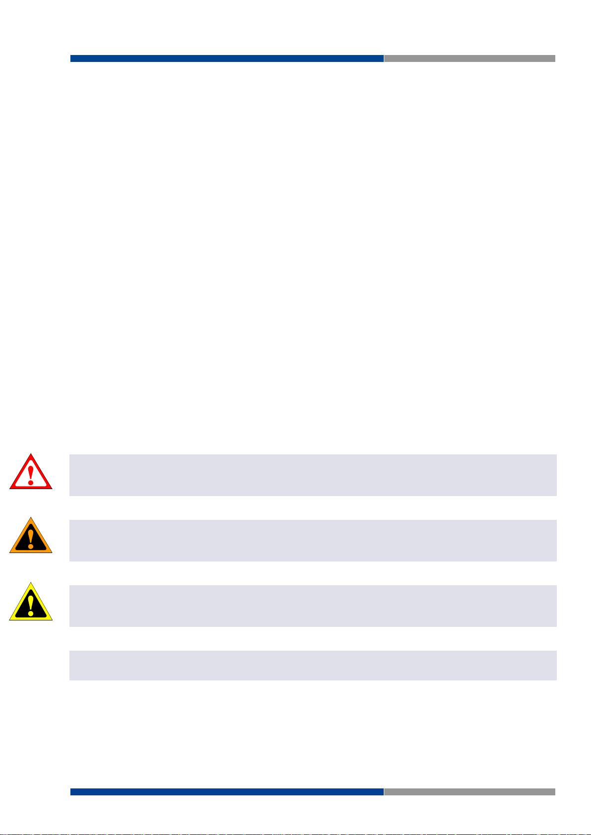
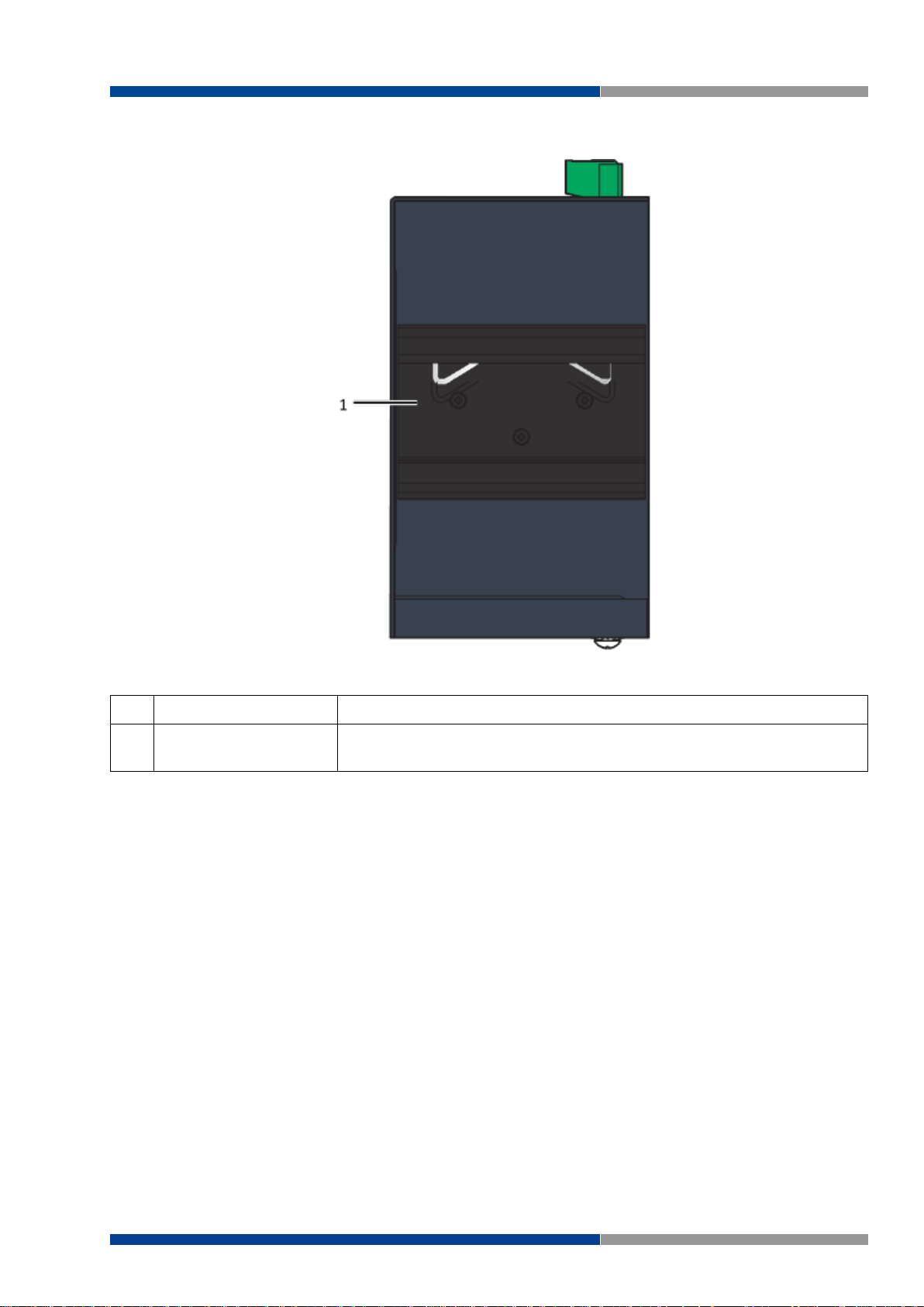
No.
Item
Description
1
System LED panel
See section "System LED Panel" for further details.
2
ETH port
Eight 10/100BaseT(X) ports.
Port numbers in black are designated for port based Quality of Service
(QoS) functionality.
3
LNK/ACT LED
Link activity LED.
4
Speed LED
Fast Ethernet:
Amber: 100M
Off: 10M
3.2 Hardware Views
3.2.1 Front View
The following view applies to to WIENET FS 8-PN-W, WIENET FS 8-EI-W.
Figure 3.1 Front View
14 Wieland Electric GmbH | BA001047 (Rev. A) | 06/2018
Page 15
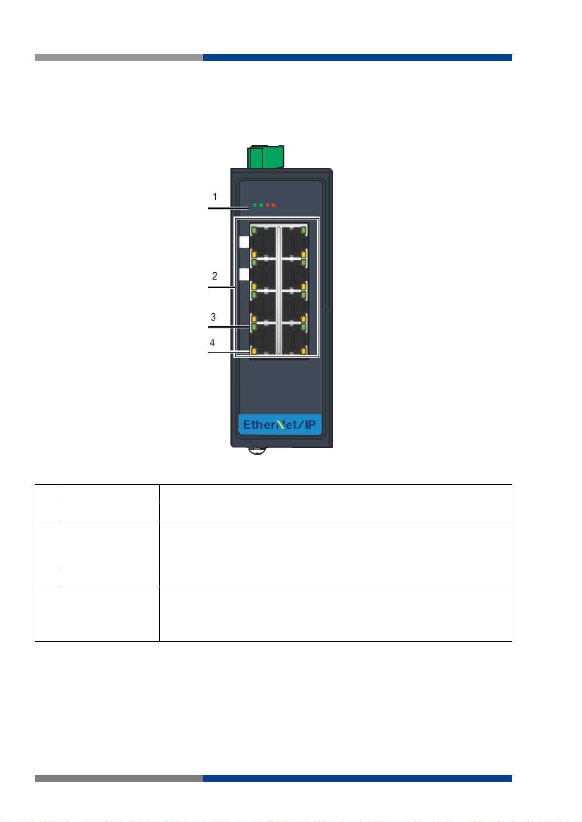
The following view applies to WIENET FS 16-PN-W, WIENET FS 16-EI-W.
No.
Item
Description
1
System LED panel
See section "System LED Panel" for further details.
2
ETH port
Sixteen 10/100BaseT(X) ports.
Port numbers in black are designated for port based Quality of Service
(QoS) functionality.
3
LNK/ACT LED
Link activity LED.
4
Speed LED
Fast Ethernet:
Amber: 100M
Off: 10M
3 Product Overview
Figure 3.2 Front View
Wieland Electric GmbH | BA001047 (Rev. A) | 06/2018 15
Page 16
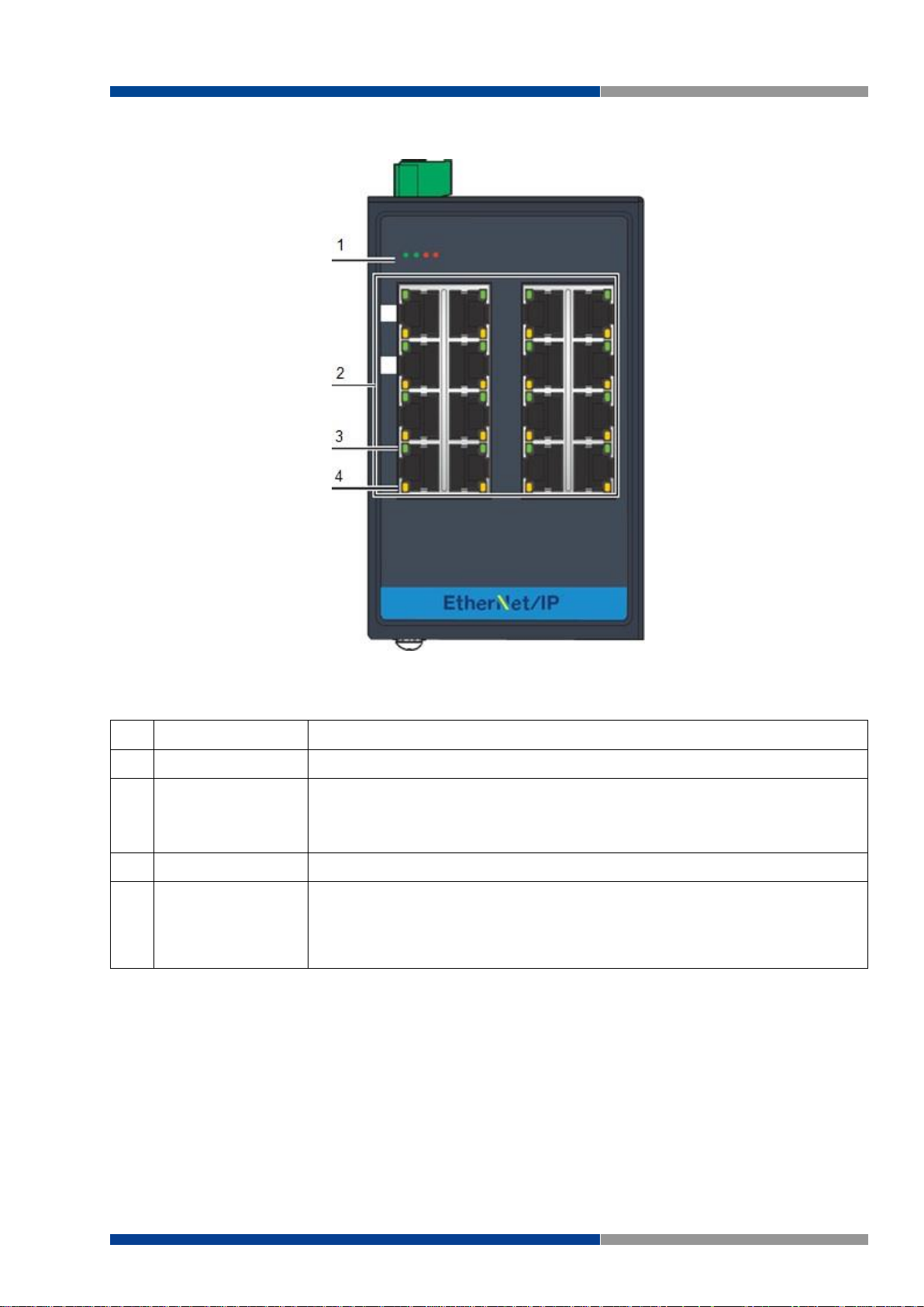
3 Product Overview
No.
LED
Name
LED Color
Description
1
PW1 LED
Solid green
Powered up.
Off
Powered down or not installed.
2
PW2 LED
Solid green
Powered up.
Off
Powered down or not installed.
3
P-Fail
Solid red
When PW1 or PW2 is disconnected.
Off
When PW1 and PW2 is connected.
4
Loop
Solid red
When loop detected.
Off
No loop detected.
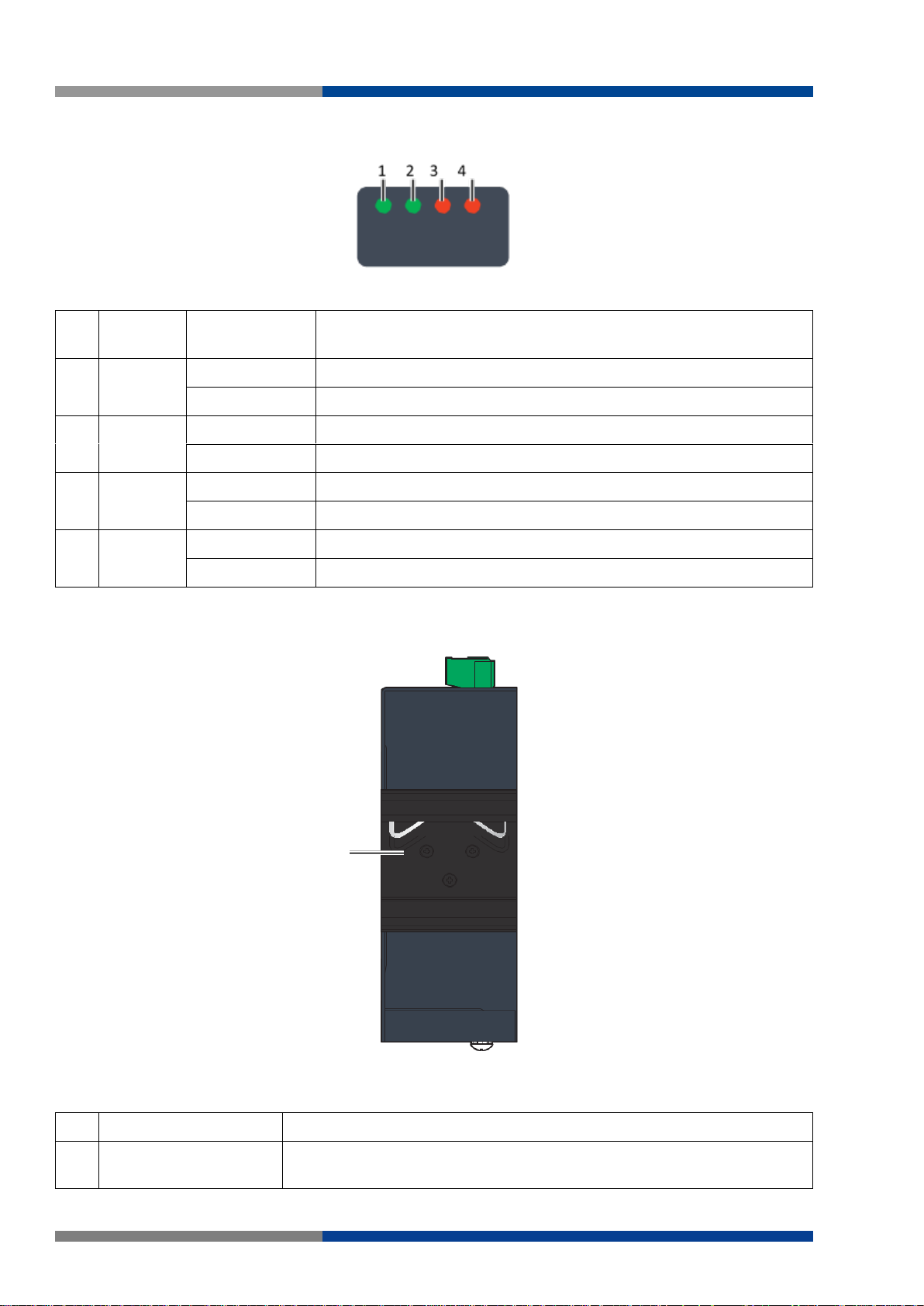
No.
Item
Description
1
DIN-Rail mounting
plate
Mounting plate used for the installation to a standard DIN rail.
1
3.2.1.1 System LED Panel
Figure 3.3 System LED Panel
3.2.2 Rear View
The following view applies to WIENET FS 8-PN-W, WIENET FS 8-EI-W.
Figure 3.4 Rear View
16 Wieland Electric GmbH | BA001047 (Rev. A) | 06/2018
Page 17
The following view applies to WIENET FS 16-PN-W, WIENET FS 16-EI-W.
No.
Item
Description
1
DIN-Rail mounting
plate
Mounting plate used for the installation to a standard DIN rail.
3 Product Overview
Figure 3.5 Rear View
Wieland Electric GmbH | BA001047 (Rev. A) | 06/2018 17
Page 18
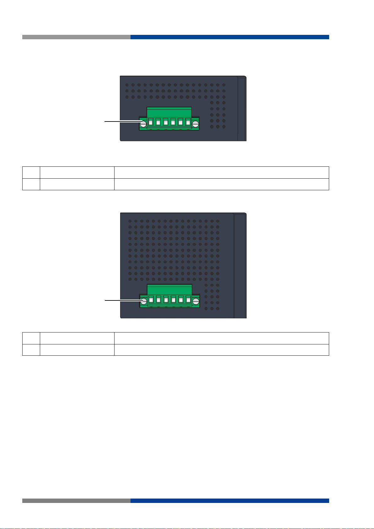
3 Product Overview
No.
Item
Description
1
Terminal block
Connect cabling for power and alarm wiring.
No.
Item
Description
1
Terminal block
Connect cabling for power and alarm wiring.
1
1
3.2.3 Top View
The following view applies to WIENET FS 8-PN-W, WIENET FS 8-EI-W.
Figure 3.6 Top View
The following view applies to WIENET FS 16-PN-W, WIENET FS 16-EI-W.
Figure 3.7 Top View
18 Wieland Electric GmbH | BA001047 (Rev. A) | 06/2018
Page 19
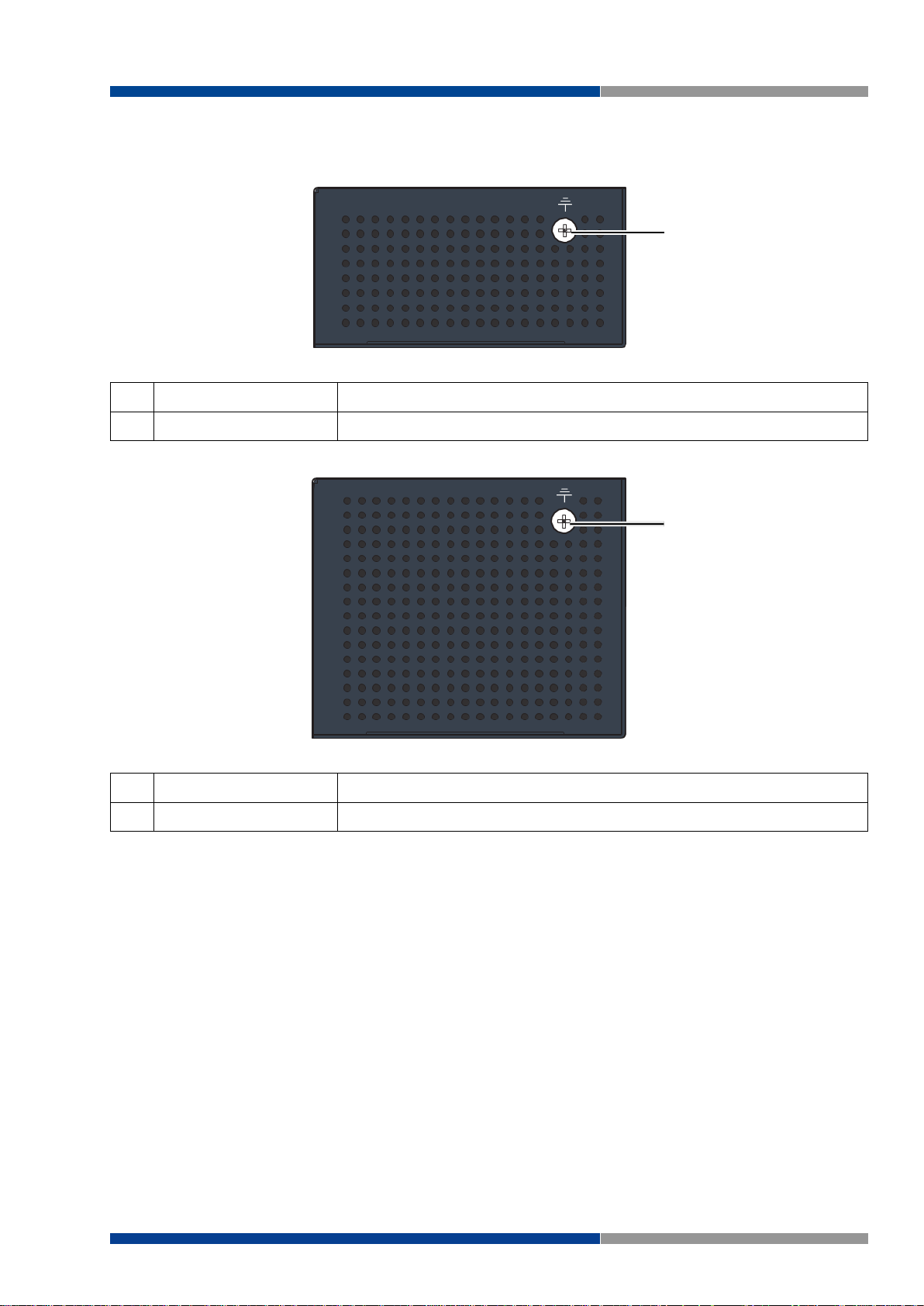
3.2.4 Bottom View
No.
Item
Description
1
Ground Terminal
Screw terminal used to ground chassis.
No.
Item
Description
1
Ground Terminal
Screw terminal used to ground chassis.
1
1
The following view applies to WIENET FS 8-PN-W, WIENET FS 8-EI-W.
Figure 3.8 Bottom View
The following view applies to WIENET FS 16-PN-W, WIENET FS 16-EI-W.
3 Product Overview
Figure 3.9 Bottom View
Wieland Electric GmbH | BA001047 (Rev. A) | 06/2018 19
Page 20

4 Switch Installation
4 Switch Installation
4.1 Installation Guidelines
The following guidelines are provided to optimize the device performance. Review the guidelines before
installing the device.
Make sure cabling is away from sources of electrical noise. Radios, power lines, and fluorescent
lighting fixtures can interference with the device performance.
Make sure the cabling is positioned away from equipment that can damage the cables.
Operating environment is within the ranges listed range, see "Specifications" in section 3.1.
Relative humidity around the Switch does not exceed 95 percent (noncondensing).
Altitude at the installation site is not higher than 10,000 feet.
In 10/100 fixed port devices, the cable length from the Switch to connected devices can not exceed
100 meters (328 ft).
Make sure airflow around the Switch and respective vents is unrestricted. Without proper airflow
the Switch can overheat. To prevent performance degradation and damage to the Switch, make
sure there is clearance at the top and bottom and around the exhaust vents.
4.1.1 Connecting Hardware
These instructions will explain how to find a proper location for your Switch, how to connect to the network, hook up the power cable, and connect to wienet FS 8/16-XX-W.
4.2 Verifying Switch Operation
Before installing the device in a rack or on a wall, power on the Switch to verify that the Switch passes the
power-on self-test (POST). To connect the cabling to the power source, see "Power Supply Installation" in
section 4.5.
At startup (POST), the System LED blinks green, while the remaining LEDs are a solid green. Once the
Switch passes POST self-test, the System LED turns green. The other LEDs turn off and return to their
operating status. If the Switch fails POST, the System LED Switches to an amber state.
After a successful self-test, power down the Switch and disconnect the power supply. The Switch is now
ready for installation on its final location.
20 Wieland Electric GmbH | BA001047 (Rev. A) | 06/2018
Page 21
4 Switch Installation
NOTE
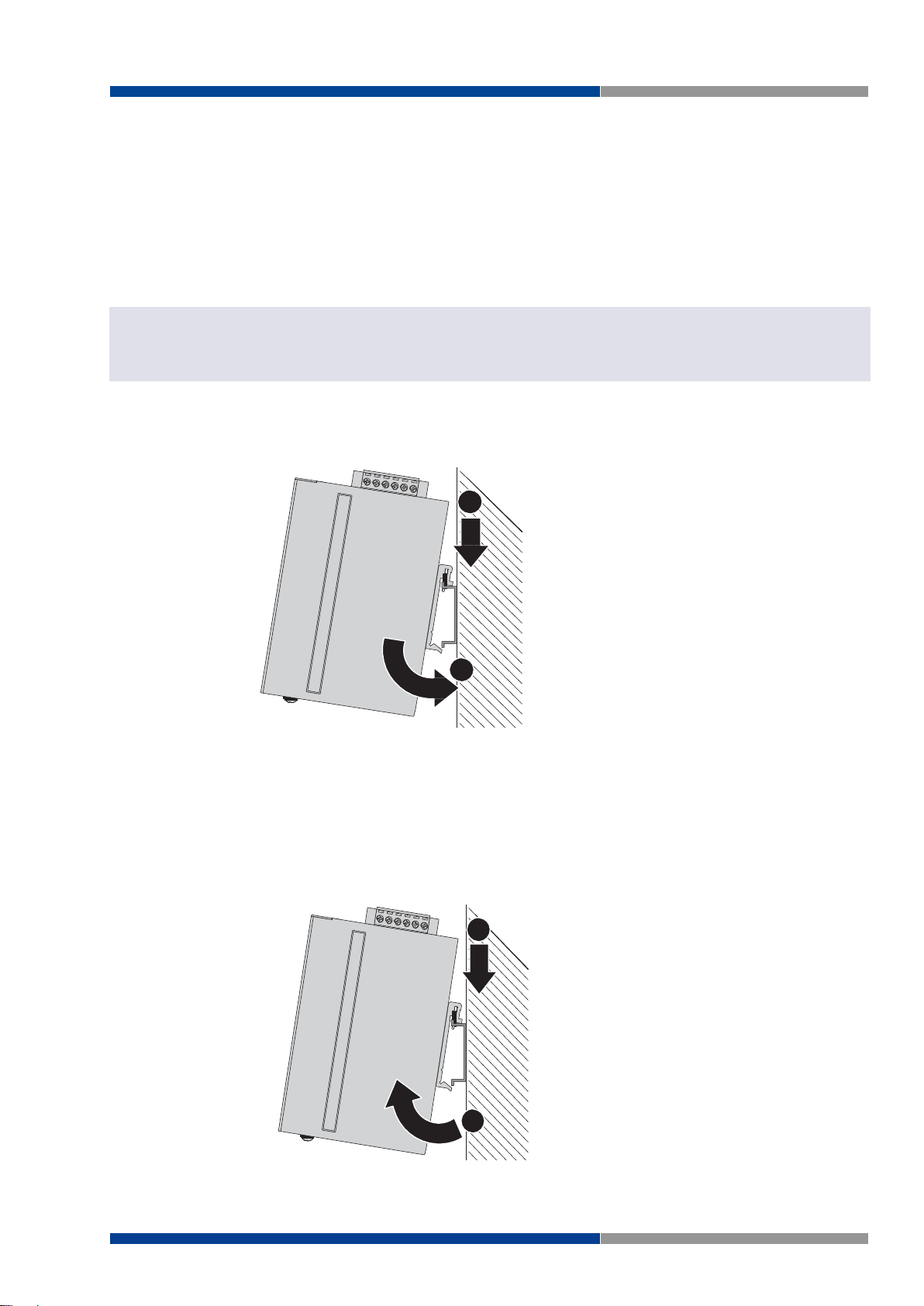
Figure 4.1 Installing the DIN-Rail Mounting Kit
DIN Rail
1
2
DIN Rail
1
2
Figure 4.2 Removing the DIN-Rail
4.3 Installing the Switch
4.3.1 DIN Rail Mounting
The DIN rail mount option is the quickest installation option. Additionally, it optimizes the use of rail space.
The metal DIN rail kit is secured to the rear of the Switch. The device can be mounted onto a standard
35mm (1.37") x 75 mm (3") height DIN rail. The devices can be mounted vertically or horizontally. Refer to
the following guidelines for further information.
Note
A corrosion-free mounting rail is advisable.
When installing, make sure to allow for enough space to properly install the cabling.
4.3.1.1 Installing the DIN-Rail Mounting Kit
1. Insert the top back of the mounting bracket over the DIN rail.
2. Push the bottom of the Switch towards the DIN rail until it snaps into place.
4.3.1.2 Removing the DIN-Rail Mounting Kit
1. Push the Switch down to free the bottom of the plate from the DIN rail.
2. Rotate the bottom of the device towards you and away from the DIN rail.
3. Once the bottom is clear of the DIN rail, lift the device straight up to unhook it from the DIN
rail.
Wieland Electric GmbH | BA001047 (Rev. A) | 06/2018 21
Page 22
4 Switch Installation
NOTE
Figure 4.3 Installing Wall Mount Plates
Figure 4.4 Securing Wall Mounting Screws
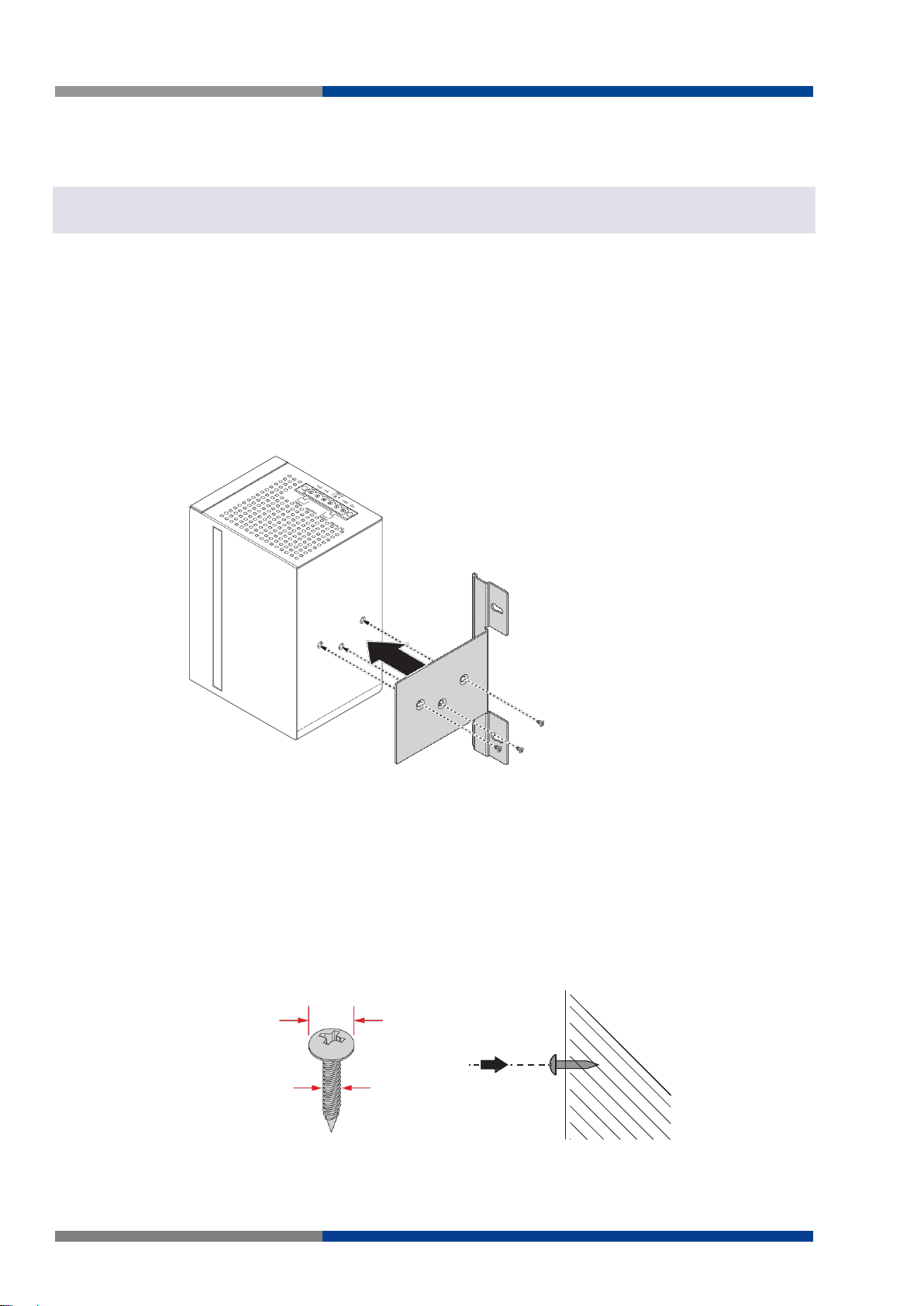
4.5 mm
3.0 mm
2.0 mm
4.3.2 Wall-Mounting
The wall mounting option provides better shock and vibration resistance than the DIN rail vertical mount.
Note
When installing, make sure to allow for enough space to properly install the cabling.
Before the device can be mounted on a wall, you will need to remove the DIN rail plate.
1. Rotate the device to the rear side and locate the DIN mounting plate.
2. Remove the screws securing the DIN mounting plate to the rear panel of the Switch.
3. Remove the DIN mounting plate. Store the DIN mounting plate and provided screws for later
use.
4. Align the wall mounting plates on the rear side. The screw holes on the device and the mount-
ing plates must be aligned, see the following illustration.
5. Secure the wall mount plates with M3 screws, see the following figure. Once the wall mount-
ing plates are secure on the device, you will need to attach the wall screws (x3).
6. Locate the installation site and place the Switch against the wall, making sure it is the final
installation location.
7. Use the wall mount plates as a guide to mark the locations of the screw holes.
8. Drill four holes over the four marked locations on the wall, keeping in mind that the holes must
accommodate wall sinks in addition to the screws.
9. Insert the wall sinks into the walls.
10. Insert the screws into the wall sinks. Leave a 2 mm gap between the wall and the screw head
to allow for wall mount plate insertion.
22 Wieland Electric GmbH | BA001047 (Rev. A) | 06/2018
Page 23
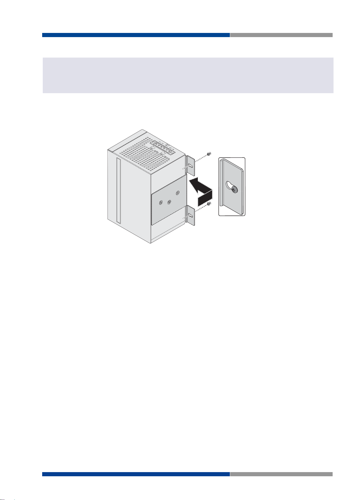
4 Switch Installation
NOTE
Figure 4.5 Wall Mount Installation
Note
Make sure the screws dimensions are suitable for use with the wall mounting plate.
Do not completely tighten the screws into the wall. A final adjustment may be needed before fully securing the wall
mounting plates on the wall.
11. Align the wall mount plate over the screws on the wall.
12. Install the wall mount plate on the screws and slide it forward to lock in place, see the following
figure.
13. Once the device is installed on the wall, tighten the screws to secure the device.
Wieland Electric GmbH | BA001047 (Rev. A) | 06/2018 23
Page 24
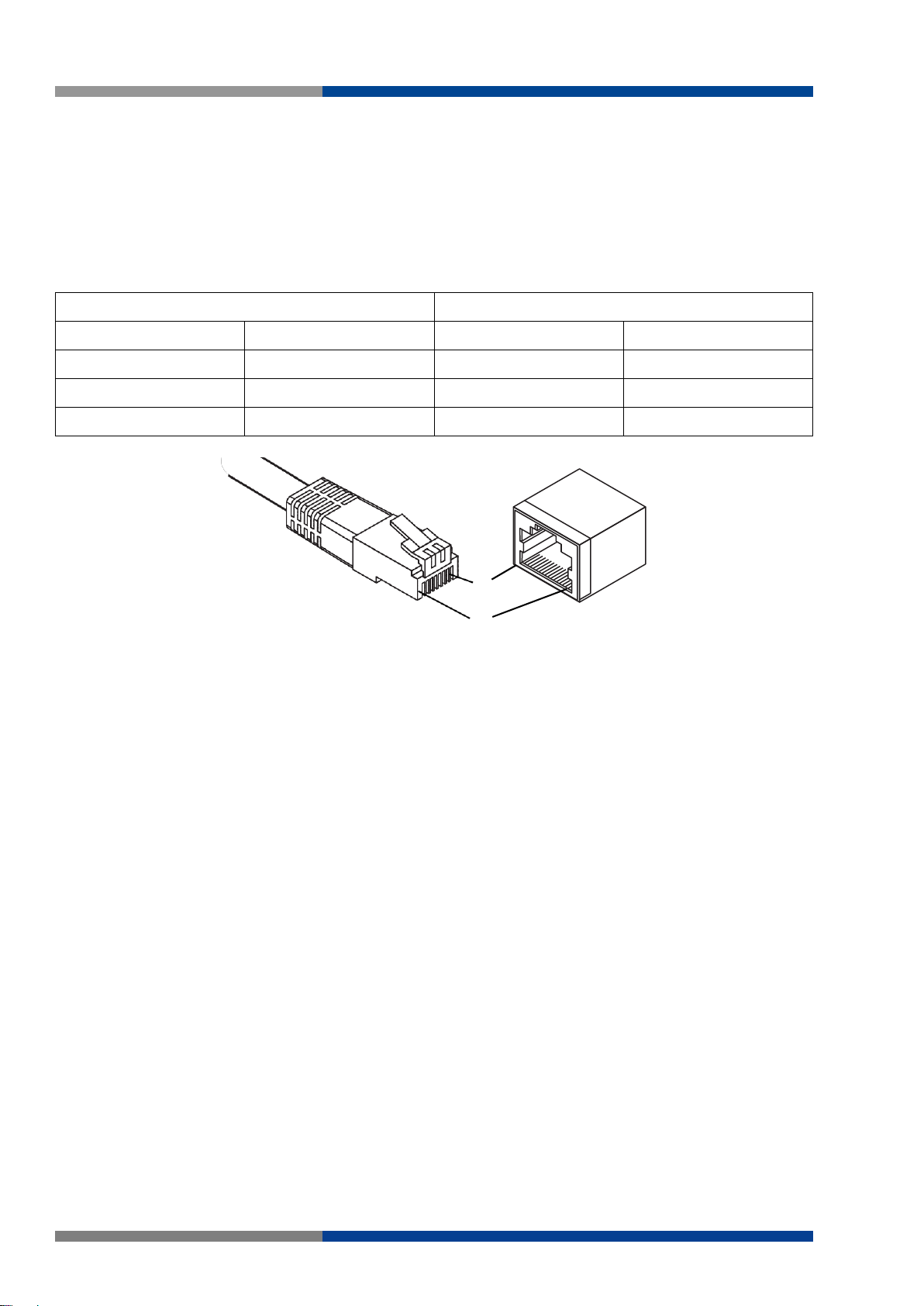
4 Switch Installation
Straight-thru Cable Wiring
Cross-over Cable Wiring
Pin 1
Pin 1
Pin 1
Pin 3
Pin 2
Pin 2
Pin 2
Pin 6
Pin 3
Pin 3
Pin 3
Pin 1
Pin 6
Pin 6
Pin 6
Pin 2
Figure 4.6 Ethernet Plug & Connector Pin Position
8
1
4.4 Connecting the Switch to Ethernet Ports
4.4.1 RJ45 Ethernet Cable Wiring
For RJ45 connectors, data-quality, twisted pair cabling (rated CAT5 or better) is recommended. The connector bodies on the RJ45 Ethernet ports are metallic and connected to the GND terminal. For best performance, use shielded cabling. Shielded cabling may be used to provide further protection.
Maximum cable length: 100 meters (328 ft.) for 10/100BaseT.
24 Wieland Electric GmbH | BA001047 (Rev. A) | 06/2018
Page 25
4 Switch Installation
WARNING
ATTENTION
ATTENTION
NOTE
Single
Redundant
Figure 4.7 Power Wiring for wienet FS 8/16-EI-W
4.5 Power Supply Installation
4.5.1 Overview
Warning!
Power down and disconnect the power cord before servicing or wiring the Switch.
Attention!
Do not disconnect modules or cabling unless the power is first switched off.
The device only supports the voltage outlined in the type plate. Do not use any other power components except
those specifically designated for the switch device.
Attention!
Disconnect the power cord before installation or cable wiring.
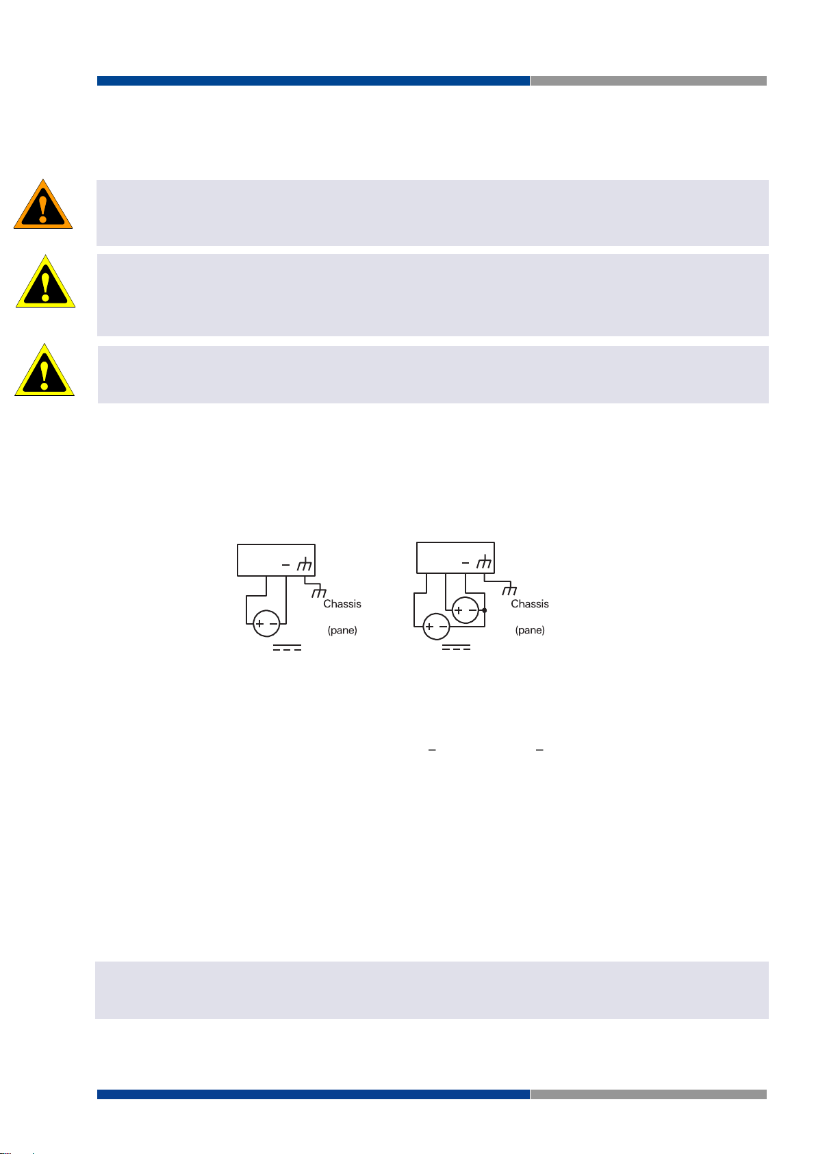
The Switches can be powered by using the same DC source used to power other devices. A DC voltage
range of 12 to 48 VDC must be applied between the V1+ terminal and the V1-terminal (PW1), see the
following illustrations. A Class 2 power supply is required to maintain a UL60950 panel listing. The chassis
ground screw terminal should be tied to the panel or chassis ground. A redundant power configuration is
supported through a secondary power supply unit to reduce network down time as a result of power loss.
GND
GND
4.5.2 Considerations
Take into consideration the following guidelines before wiring the device:
The Terminal Block (CN1) is suitable for 12 24 AWG (3.31 0.205 mm2). Torque value 0.8 Nm
(7 lb-in).
The cross sectional area of the earthing conductors shall be at least 4 mm2.
Calculate the maximum possible current for each power and common wire. Make sure the power
draw is within limits of local electrical code regulations.
For best practices, route wiring for power and devices on separate paths.
Do not bundle together wiring with similar electrical characteristics.
Make sure to separate input and output wiring.
Label all wiring and cabling to the various devices for more effective management and servicing.
Note
Routing communications and power wiring through the same conduit may cause signal interference. To avoid interference and signal degradation, route power and communications wires through separate conduits.
Wieland Electric GmbH | BA001047 (Rev. A) | 06/2018 25
Page 26
4 Switch Installation
ATTENTION
ATTENTION
ATTENTION
ATTENTION
ATTENTION
NOTE
Connection to
Drain Wire with Lug
Figure 4.8 Grounding Connection
4.5.3 Grounding the device
Attention!
Do not disconnect modules or cabling unless the power is first switched off.
The device only supports the voltage outlined in the type plate. Do not use any other power components except
those specifically designated for the switch device.
Attention!
Before connecting the device properly ground the device. Lack of a proper grounding setup may result in a safety
risk and could be hazardous.
Attention!
Do not service equipment or cables during periods of lightning activity.
Attention!
Do not service any components unless qualified and authorized to do so.
Attention!
Do not block air ventilation holes.
Electromagnetic Interference (EMI) affects the transmission performance of a device. By properly grounding the device to earth ground through a drain wire, you can setup the best possible noise immunity and
emissions.
Grounding Point
By connecting the ground terminal by drain wire to earth ground the Switch and chassis can be ground.
Note
Before applying power to the grounded Switch, it is advisable to use a volt meter to ensure there is no voltage difference between the power supply's negative output terminal and the grounding point on the Switch.
26 Wieland Electric GmbH | BA001047 (Rev. A) | 06/2018
Page 27

4 Switch Installation
ATTENTION
WARNING
DC 12 48V
PWR2
1A@24V
PWR1
V2- V2+ V1- V1+
P-Fail
Figure 4.9 Terminal Receptor: Relay Contact
DC 12 48V
PWR2
1A@24V
PWR1
V2- V2+ V1- V1+
P-Fail
Figure 4.10 Terminal Receptor: Power Input Contacts
4.5.4 Wiring a Relay Contact
The following section details the wiring of the relay output. The terminal block on the wienet FS 8/16-XXW is wired and then installed onto the terminal receptor located on the wienet FS 8/16-XX-W.
The terminal receptor includes a total of six pins: two for PWR1, two for PWR2 and two for a fault circuit.
4.5.5 Wiring the Power Inputs
Attention!
Do not disconnect modules or cabling unless the power is first switched off.
The device only supports the voltage outlined in the type plate. Do not use any other power components except
those specifically designated for the switch device
Warning!
Power down and disconnect the power cord before servicing or wiring the Switch.
There are two power inputs for normal and redundant power configurations. The power input 2 is used for
wiring a redundant power configuration. See the following for terminal block connector views.
To wire the power inputs:
Make sure the power is not connected to the Switch before proceeding.
1. Loosen the screws securing terminal block to the terminal block receptor.
Wieland Electric GmbH | BA001047 (Rev. A) | 06/2018 27
Page 28
4 Switch Installation
Figure 4.11 Removing a Terminal Block
Figure 4.12 Installing DC Wires in a Terminal Block
Loosening Wire-clamp Screws
Installing DC Wires
Securing Wire-clamp Screws
Figure 4.13 Installing DC Wires in a Terminal Block
2. Remove the terminal block from the Switch.
3. Insert a small flat-bladed screwdriver in the V1+/V1- wire-clamp screws, and loosen the
screws.
4. Insert the negative/positive DC wires into the V+/V- terminals of PW1. If setting up power
redundancy, connect PW2 in the same manner.
5. Tighten the wire-clamp screws to secure the DC wires in place.
28 Wieland Electric GmbH | BA001047 (Rev. A) | 06/2018
Page 29
4 Switch Installation
Figure 4.14 Securing a Terminal Block to a Receptor
6. Align the terminal block over the terminal block receptor on the Switch.
7. Insert the terminal block and press it in until it is flush with the terminal block receptor.
8. Tighten the screws on the terminal block to secure it to the terminal block receptor.
If there is no gap between the terminal block and the terminal receptor, the terminal block is seated correctly.
Wieland Electric GmbH | BA001047 (Rev. A) | 06/2018 29
Page 30

5 Managing Switch
NOTE
NOTE
5 Managing Switch
5.1 First Time Setup
5.1.1 Overview
The Industrial Ethernet Managed Switch is a configurable device that facilitates the interconnection of
Ethernet devices on an Ethernet network. This includes computers, operator interfaces, I/O, controllers,
RTUs, PLCs, other switches/hubs or any device that supports the standard IEEE 802.3 protocol.
This Switch has all the capabilities of a store and forward Ethernet switch plus advanced management
features such as SNMP, RSTP and port mirroring. This manual details how to configure the various management parameters in this easy to use switch.
5.1.2 Introduction
To take full advantage of all the features and resources available from the Switch, it must be configured
for your network.
The Switch implements Rapid Spanning Tree Protocol (RSTP) and Simple Network Management Protocol
(SNMP) to provide most of the services offered by the Switch. Rapid Spanning Tree Protocol allows managed Switches to communicate with each other to ensure that there exists only one active route between
each pair of network nodes and provides automatic failover to the next available redundant route. A brief
explanation of how RSTP works is given in the Spanning Tree section.
The Switch is capable of communicating with other SNMP capable devices on the network to exchange
management information. This statistical/derived information from the network is saved in the Management Information Base (MIB) of the Switch. The MIB is divided into several different information storage
groups. These groups will be elaborated in detail in the Management and SNMP information section of this
document. The Switch implements Internet Group Management Protocol (IGMP) to optimize the flow of
multicast traffic on your network.
The Switch supports both port-based and tag-based Virtual LANs for flexible integration with VLAN-aware
networks with support for VLAN-unaware devices.
5.1.3 Administrative Interface Access
There are several administrative interfaces to the Switch:
1. A graphical web interface accessible via the Switch's built-in web server, supporting HTTP.
Note
This is the recommended method for managing the Switch.
2. An SNMP interface can be used to read/write many settings
5.1.4 Using the Graphical (Web) Interface
The graphical interface is provided via a web server in the Switch and can be accessed via a web browser
such as Opera, Mozilla, or Internet Explorer.
Note
JavaScript must be supported and enabled in your browser for the graphical interface to work correctly.
HTTP and HTTPS (secure HTTP) are supported for access to the web server. By default, both protocols are
enabled. Either or both may be disabled to secure the Switch. (See the Remote Access Security topic in
this section.)
To access the graphical interface, enter a URL like HTTP:// 10.0.50.1 in your browser's address bar. Replace
"http" with "https" to use secure http and replace "10.0.50.1" with your Switch's IP address if you have
changed it from the factory default.
30 Wieland Electric GmbH | BA001047 (Rev. A) | 06/2018
Page 31

5 Managing Switch
NOTE
NOTE
The web server in the Switch uses a signed security certificate. When you access the server via https, you
may see a warning dialog indicating that the certificate was signed by an unknown authority. This is expected and to avoid this message in the future you can choose to install the certificate on your computer.
Note
This manual describes and depicts the web user interface in detail. The terminal interface is not specifically shown
but is basically the same.
5.1.5 Configuring the Switch for Network Access
To control and monitor the Switch via the network, it must be configured with basic network settings,
including an IP address and subnet mask. Refer to the quick start guide in Section 1 for how to access your
Switch initially.
To configure the Switch for network access, select [Add Menu Address Here] to reach the System Settings
menu. The settings in this menu control the Switch's general network configuration.
DHCP Enabled/Disabled: The Switch can automatically obtain an IP address from a server using
the Dynamic Host Configuration Protocol (DHCP). This can speed up initial set up, as the network
administrator does not have to find an open IP address.
IP Address and subnet mask configuration: The IP address for the Switch can be changed to a user-
defined address along with a customized subnet mask to separate subnets.
Note
Advanced users can set the IP address to 0.0.0.0 to disable the use of an IP address for additional security. However,
any features requiring an IP address (i.e., web interface, etc.) will no longer be available.
Default Gateway Selection: A Gateway Address is chosen to be the address of a router that con-
nects two different networks. This can be an IP address or a Fully Qualified Domain Name (FQDN)
such as "domainname.org".
NTP Server: The IP address or domain name of an NTP (Network Time Protocol) server from which
the Switch may retrieve the current time at startup. Please note that using a domain name requires
that at least one domain name server be configured.
5.1.6 Configuring the Ethernet Ports
The Switch comes with default port settings that should allow you to connect to the Ethernet Ports with
out any necessary configuration. Should there be a need to change the name of the ports, negotiation
settings or flow control settings, you can do this in the Port Configuration menu. Access this menu by
selecting Setup from the Main menu, and then selecting Main Settings.
Port Name: Each port in the managed Switch can be identified with a custom name. Specify a
name for each port here.
Admin: Ports can be enabled or disabled in the managed Switch. For ports that are disabled, they
are virtually non-existent (not visible in terms of switch operation or spanning tree algorithm).
Choose to enable or disable a port by selecting Enabled or Disabled, respectively.
Negotiation: All copper ports and gigabit fiber ports in the managed Switch are capable of auto-
negotiation such that the fastest bandwidth is selected. Choose to enable auto-negotiation or use
fixed settings. 100Mbps Fiber ports are Fixed speed only.
Speed/Duplex/Flow Control: The managed Switch accepts three local area network Ethernet Stand-
ards. The first standard, 10BASE-T, runs 10Mbps with twisted pair Ethernet cable between network
interfaces. The second local area network standard is 100BASE-T, which runs at 100Mbps over the
same twisted pair Ethernet cable. Lastly, there is 100BASE-F, which enables fast Ethernet
(100Mbps) over fiber.
Wieland Electric GmbH | BA001047 (Rev. A) | 06/2018 31
Page 32

5 Managing Switch
These options are available:
10h 10 Mbps, Half Duplex
10 Mbps, Full Duplex
100 Mbps, Half Duplex
100 Mbps, Full Duplex
On managed Switches with gigabit combination ports, those ports with have two rows, a standard row of
check boxes and a row labeled "SFP" with radio buttons. The SFP setting independently sets the speed at
which a transceiver will operate if one is plugged in. Otherwise, the Switch will use the fixed Ethernet port
and the corresponding settings for it.
32 Wieland Electric GmbH | BA001047 (Rev. A) | 06/2018
Page 33

5 Managing Switch
5.2 Web Browser Configuration
The Switch has an HTML based user interface embedded in the flash memory. The interface offers an easy
to use means to manage basic and advanced switch functions. The interface allows for local or remote
switch configuration anywhere on the network.
The interface is designed for use with [Internet Explorer (6.0), Chrome, Firefox].
5.2.1 Preparing for Web Configuration
The interface requires the installation and connection of the Switch to the existing network. A PC also
connected to the network is required to connect to the Switch and access the interface through a web
browser. The required networking information is provided as follows:
IP address: 10.0.50.2
Subnet mask: 255.255.255.0
Default gateway: 10.0.50.254
User name: admin
Password: wienet123
Wieland Electric GmbH | BA001047 (Rev. A) | 06/2018 33
Page 34

5 Managing Switch
Figure 5.1 Login Screen
5.3 Log In
To access the login window, connect the device to the network, see "Connecting the Switch to Ethernet
Ports" in section 4.4. Once the Switch is installed and connected, power on the Switch see the following
procedures to log into your Switch.
When the Switch is first installed, the default network configuration is set to DHCP enabled. You will need
to make sure your network environment supports the Switch setup before connecting it to the network.
1. Launch your web browser on a computer.
2. In the browser's address bar type in the Switch's default IP address (10.0.50.1). The login
screen displays.
3. Enter the default user name and password (admin/admin) to log into the management inter-
face. You can change the default password after you have successfully logged in.
4. Click Login to enter the management interface.
34 Wieland Electric GmbH | BA001047 (Rev. A) | 06/2018
Page 35

5 Managing Switch
Figure 5.2 Changing a Default Password
5.4 Recommended Practices
One of the easiest things to do to help increase the security posture of the network infrastructure is to
implement a policy and standard for secure management. This practice is an easy way to maintain a healthy
and secure network.
After you have performed the basic configurations on your Switches, the following is a recommendation
which is considered best practice policy.
5.4.1 Changing Default Password
In keeping with good management and security practices, it is recommended that you change the default
password as soon as the device is functioning and setup correctly. The following details the necessary
steps to change the default password.
To change the password:
1. Navigate to Tools > User Account.
2. From the User drop-down menu, select the Admin (default) account.
3. In the User Name field, enter admin for this account. It is not necessary to change the user
name, however, a change in the default settings increases the security settings.
4. In the Password field, type in the new password. Re-type the same password in the Retype
Password field.
5. Click Apply to change the current account settings.
After saving all the desired settings, perform a system save (Tools > Save Configuration). The changes
are saved.
Wieland Electric GmbH | BA001047 (Rev. A) | 06/2018 35
Page 36

5 Managing Switch
Item
Description
System Name
Click Switch to enter the system name: up to 128 alphanumeric characters (default is Switch).
System Location
Click Default to enter the location: up to 256 alphanumeric characters (default is
Default).
System Contact
Click Default to enter the contact person: up to 128 alphanumeric characters (default is Default).
MAC Address
Displays the MAC address of the Switch.
IP Address
Displays the assigned IP address of the Switch.
Subnet Mask
Displays the assigned subnet mask of the Switch.
Gateway
Displays the assigned gateway of the Switch.
Loader Version
Displays the current loader version of the Switch.
Loader Date
Displays the current loader build date of the Switch.
Firmware Version
Displays the current firmware version of the Switch.
Firmware Date
Displays the current firmware build date of the Switch.
System Object ID
Displays the base object ID of the Switch.
System Up Time
Displays the time since the last Switch reboot.
Figure 5.3 Monitoring > Device Information
5.5 Monitoring
5.5.1 Device Information
The Device Information menu lists information, such as: System Name, System Location, MAC Address,
Firmware version, and more, pertaining to the system. The information is for review only. To modify the
device information, see the respective item within the user interface.
To access this page, click Monitoring > Device Information.
The following table describes the items in the previous figure.
36 Wieland Electric GmbH | BA001047 (Rev. A) | 06/2018
Page 37

5 Managing Switch
Item
Description
Target
Click the drop-down menu to select a target to store the log messages.
Buffered: Store log messages in RAM. All log messages are cleared after
system reboot.
File: Store log messages in a file.
Severity
The setting allows you to designate a severity level for the Logging Message Filter
function.
Click the drop-down menu to select the severity level target setting. The level options are:
emerg: Indicates system is unusable. It is the highest level of severity.
alert: Indicates action must be taken immediately.
crit: Indicates critical conditions.
error: Indicates error conditions.
warning: Indicates warning conditions.
notice: Indicates normal but significant conditions.
info: Indicates informational messages.
debug: Indicates debug-level messages
Category
Click the drop-down menu to select the category level target setting.
View
Click View to display all Logging Information and Logging Message information.
Refresh
Click Refresh to update the screen.
Clear buffered
messages
Click Clear buffered messages to clear the logging buffer history list.
Figure 5.4 Monitoring > Logging Message
5.5.2 Logging Message
The Logging Message Filter page allows you to enable the display of logging message filter.
To access this page, click Monitoring > Logging Message.
The following table describes the items in the previous figure.
The ensuing table for Logging Information table settings are informational only: Target, Severity and Category.
The ensuing table for Logging Message table settings are informational only: No., Time Stamp, Category,
Severity and Message.
Wieland Electric GmbH | BA001047 (Rev. A) | 06/2018 37
Page 38

5 Managing Switch
Item
Description
Port
Click the drop-down menu to select a port and its captured statistical setting values.
Clear
Click Clear to clear the counter selections.
Item
Description
Refresh period
Click the drop-down menu to select and designate a period (second intervals) to
refresh the information (TX and RX) listings.
IFG
Click the drop-down menu to enable or disable the Interframe Gap (IFG) statistic.
Figure 5.5 Monitoring > Port Monitoring > Port Statistics
Figure 5.6 Monitoring > Port Monitoring > Port Utilization
5.5.3 Port Monitoring
Port Network Monitor is a bandwidth and network monitoring tool for the purpose of capturing network
traffic and measuring of network throughput. The monitoring functionality includes listing of port statistics
as well as port utilization.
5.5.3.1 Port Statistics
To access this page, click Monitoring > Port Monitoring > Port Statistics.
The following table describes the items in the previous figure.
The ensuing table for IF MIB Counters settings are informational only: ifInOctets, ifInUcastPkts, ifInNUcastPkts, ifInDiscards, ifOutOctets, ifOutUcastPkts, ifOutNUcastPkts, ifOutDiscards, ifInMulticastPkts,
ifInBroadcastPkts, ifOutMulticastPkts and ifOutBroadcastPkts.
The ensuing table for Ether-Like MIB Counters settings are informational only: dot3StatsAlignmentErrors,
dot3StatsFCSErrors, dot3StatsSingleCollisionFrames, dot3StatsMultipleCollisionFrames, dot3StatsDeferredTransmissions, dot3StatsLateCollisions, dot3StatsExcessiveCollisions, dot3StatsFrameTooLongs,
dot3StatsSymbolErrors, dot3ControlInUnknownOpcodes, dot3InPauseFrames and dot3OutPauseFrames.
5.5.3.2 Port Utilization
To access this page, click Monitoring > Port Monitoring > Port Utilization.
The following table describes the items in the previous figure.
38 Wieland Electric GmbH | BA001047 (Rev. A) | 06/2018
Page 39

5 Managing Switch
Item
Descriptio
Clear
Click Clear to reset LLDP Statistics of all the interfaces.
Refresh
Click Refresh to update the data on the screen with the present state of the data in
the Switch.
5.5.4 Link Aggregation
The Link Aggregation function provides LAG information for each trunk. It displays membership status,
link state and membership type for each port.
To access this page, click Monitoring > Link Aggregation.
The ensuing table for Link Aggregation Group Status settings are informational only: LAG, Name, Type,
Link State, Active Member and Standby Member.
The ensuing table for LACP Information settings are informational only: LAG, Port, PartnerSysId, PnKey,
AtKey, Sel, Mux, Receiv, PrdTx, AtState and PnState.
5.5.5 LLDP Statistics
The LLDP Statistics page displays the LLDP statistics.
To access this page, click Monitoring > LLDP Statistics.
Figure 5.7 Monitoring > LLDP Statistics
The following table describes the items in the previous figure.
The ensuing table for LLDP Global Statistics settings are informational only: Insertions, Deletions, Drops
and Age Outs.
The ensuing table for LLDP Port Statistics settings are informational only: Port, TX Frames (Total), RX
Frames (Total, Discarded and Errors), RX TLVs (Discarded and Unrecognized) and RX Ageouts (Total).
Wieland Electric GmbH | BA001047 (Rev. A) | 06/2018 39
Page 40

5 Managing Switch
Item
Descriptio
Clear
Click Clear to reset IGMP Statistics of all the interfaces.
Refresh
Click Refresh to update the data on the screen with the present state of the data in
the Switch.
Figure 5.8 Monitoring > IGMP Statistics
5.5.6 IGMP Statistics
The IGMP Statistics function displays statistical package information for IP multicasting.
To access this page, click Monitoring > IGMP Statistics.
The following table describes the items in the previous figure.
The ensuing table for IGMP Statistics settings are informational only: Total RX, Valid RX, Invalid RX, Other
RX, Leave RX, Report RX, General Query RX, Special Group Query RX, Special Group & Source Query RX,
Leave TX, Report TX, General Query TX, Special Group Query TX and Special Group & Source Query TX.
40 Wieland Electric GmbH | BA001047 (Rev. A) | 06/2018
Page 41

5 Managing Switch
Item
Description
Mode
Click the radio button to select the IP Address Setting mode: Static, DHCP, or
BOOTP.
IP Address
Enter a value to specify the IP address of the interface. The default is 10.0.50.1.
Subnet Mask
Enter a value to specify the IP subnet mask for the interface. The default is
255.255.255.0.
Gateway
Enter a value to specify the default gateway for the interface. The default is
10.0.50.254.
DNS Server 1
Enter a value to specify the DNS server 1 for the interface. The default is 168.95.1.1.
DNS Server 2
Enter a value to specify the DNS server 2 for the interface. The default is
168.95.192.1.
Apply
Click Apply to save the values and update the screen.
Figure 5.9 System > IP Settings
5.6 System
5.6.1 IP Settings
The IP Settings menu allows you to select a static or DHCP network configuration. The Static displays the
configurable settings for the static option.
To access this page, click System > IP Settings.
The following table describes the items in the previous figure.
The ensuing table for IP Address Information settings are informational only: DHCP State, BOOTP State,
Static IP Address, Static Subnet Mask, Static Gateway, Static DNS Server 1 and Static DNS Server 2.
Wieland Electric GmbH | BA001047 (Rev. A) | 06/2018 41
Page 42

5 Managing Switch
Item
Description
Mode
Click the radio button to enable or disable the DHCP Client Option 82 mode.
Circuit ID Format
Click the drop-down menu to set the ID format: String, Hex, User Definition.
Circuit ID String
Enter the string ID of the corresponding class.
Circuit ID Hex
Enter the hex string of the corresponding class.
Circuit ID User-Define
Enter the user definition of the corresponding class.
Remote ID Format
Click the drop-down menu to set the Remote ID format: String, Hex, User
Definition.
Remote ID String
Enter the remote string ID of the corresponding class.
Remote ID Hex
Enter the remote hex string of the corresponding class.
Remote ID User-Define
Enter the remote user definition of the corresponding class.
Apply
Click Apply to save the values and update the screen.
Figure 5.10 System > DHCP Client Option 82
5.6.2 DHCP Client Option 82
The DHCP Client Option 82 configurable Circuit ID and Remote ID feature enhances validation security by
allowing you to select naming choices suboptions. You can select a switch-configured hostname or specify
an ASCII test string for the remote ID. You can also configure an ASCII text string to override the circuit ID.
To access this page, click System > DHCP Client Option 82.
The following table describes the items in the previous figure.
The ensuing table for DHCP Client Option 82 Information table settings are informational only: Status,
Circuit ID Format, Circuit ID String, Circuit ID Hex, Circuit ID User-Define, Remote ID Format, Remote ID
String, Remote ID Hex and Remote ID User-Define.
42 Wieland Electric GmbH | BA001047 (Rev. A) | 06/2018
Page 43

5 Managing Switch
Item
Description
Status
Select the radio button to enable or disable the DHCP Auto Provisioning Setting.
Apply
Click Apply to save the values and update the screen.
Item
Description
Auto Configuration
Select the radio button to enable or disable the IPv6.
IPv6 Address
Enter the IPv6 address for the system.
Gateway
Enter the gateway address for the system.
DHCPv6 Client
Enter the DHCPv6 address for the system.
Apply
Click Apply to save the values and update the screen.
Figure 5.11 System > DHCP Auto Provision
Figure 5.12 System > IPv6 Settings
5.6.3 DHCP Auto Provision
The DHCP Auto Provision feature allows you to load configurations using a server with DHCP options.
Through the remote connection, the Switch obtains information from a configuration file available through
the TFTP server.
To access this page, click System > DHCP Auto Provision.
The following table describes the items in the previous figure.
The ensuing table for DHCP Auto Provision Information settings are informational only: Status.
5.6.4 IPv6 Settings
To access this page, click System > IPv6 Settings.
The following table describes the items in the previous figure.
The ensuing table for IPv6 Information settings are informational only: Auto Configuration, IPv6 In Use
Address, IPv6 In Use Router, IPv6 Static Address, IPv6 Static Router and DHCPv6 Client.
Wieland Electric GmbH | BA001047 (Rev. A) | 06/2018 43
Page 44

5 Managing Switch
Item
Description
Management VLAN
Click the drop-down menu to select a defined VLAN.
Apply
Click Apply to save the values and update the screen.
Figure 5.13 System > Management VLAN
5.6.5 Management VLAN
By default the VLAN is the management VLAN providing communication with the Switch management
interface.
To access this page, click System > Management VLAN.
The following table describes the items in the previous figure.
The ensuing table for Management VLAN State are informational only: Management VLAN.
44 Wieland Electric GmbH | BA001047 (Rev. A) | 06/2018
Page 45

5.6.6 System Time
Item
Description
Enable SNTP
Click the drop-down menu to select a defined VLAN.
SNTP/NTP
Server Address
Enter the address of the SNTP server. This is a text string of up to 64 characters containing the encoded unicast IP address or hostname of a SNTP server. Unicast SNTP
requests will be sent to this address. If this address is a DNS hostname, then that
hostname should be resolved into an IP address each time a SNTP request is sent to
it.
SNTP Port
Enter the port on the server to which SNTP requests are to be sent. Allowed range is
1 to 65535 (default: 123).
Manual Time
Click the drop-down menus to set local date and time of the system.
Time Zone
Click the drop-down menu to select a system time zone.
Figure 5.14 System > System Time
To access this page, click System > System Time.
5 Managing Switch
The following table describes the items in the previous figure.
Wieland Electric GmbH | BA001047 (Rev. A) | 06/2018 45
Page 46

5 Managing Switch
Item
Description
Daylight Saving
Time
Click the drop-down menu to enable or disable the daylight saving time settings.
Daylight Saving
Time Offset
Enter the offsetting variable in seconds to adjust for daylight saving time.
Recurring From
Click the drop-down menu to designate the start date/ time for daylight saving time.
Recurring To
Click the drop-down menu to designate the end date/ time for daylight saving time.
Non-Recurring
From
Click the drop-down menu to designate a start date and time for a non-recurring daylight saving time event.
Non-Recurring
To
Click the drop-down menu to designate the end date and time for a non-recurring
daylight saving time event.
Apply
Click Apply to save the values and update the screen.
The ensuing table for System Time Information settings are informational only: Current Date/Time, SNTP,
SNTP Server Address, SNTP Server Port, Time zone, Daylight Saving Time, Daylight Saving Time Offset,
From and To.
46 Wieland Electric GmbH | BA001047 (Rev. A) | 06/2018
Page 47

5 Managing Switch
Item
Description
Port
Click the drop-down menu to select the port for the L2 Switch setting
Enabled
Click the radio-button to enable or disable the Port Setting function.
Speed
Click the drop-down menu to select the port speed: Auto, Auto-10M, Auto-100M,
Auto-10/100M, 10M or 100M.
Duplex
Click the drop-down menu to select the duplex setting: Half or Full.
Flow Control
Click the radio button to enable or disable the flow control function.
Apply
Click Apply to save the values and update the screen.
Figure 5.15 L2 Switching > Port Configuration
5.7 L2 Switching
5.7.1 Port Configuration
Port Configuration describes how to use the user interface to configure LAN ports on the Switch.
To access this page, click L2 Switching > Port Configuration.
The following table describes the items in the previous figure.
The ensuing table for Port Status settings are informational only: Port, Edit (click to enter description),
Enable State, Link Status, Speed, Duplex, FlowCtrl Config and FlowCtrl Status.
5.7.2 Port Mirror
Port mirroring function allows the sending of a copy of network packets seen on one switch port to a
network monitoring connection on another switch port. Port mirroring can be used to analyze and debug
data or diagnose errors on a network or to mirror either inbound or outbound traffic (or both).
There are no preset values in the Port Mirror. The displayed values do not represent the actual setting
values.
Wieland Electric GmbH | BA001047 (Rev. A) | 06/2018 47
Page 48

5 Managing Switch
Item
Description
Session ID
Click the drop-down menu to select a port mirroring session from the list. The
number of sessions allowed is platform specific.
Monitor session
state
Click the drop-down menu to enable or disable the session mode for a selected
session ID.
Destination Port
Click the drop-down menu to select the destination port and receive all the traffic
from configured mirrored port(s).
Allow-ingress
Click the drop-down menu to select the destination port and receive all the traffic
from configured mirrored port(s).
Sniffer RX Ports
Enter the variable to define the RX port.
Sniffer TX Ports
Enter the variable to define the TX port.
Apply
Click Apply to save the values and update the screen.
Figure 5.16 L2 Switching > Port Mirror
Figure 5.17 L2 Switching > Link Aggregation > Load Balance
To access this page, click L2 Switching > Port Mirror.
The following table describes the items in the previous figure.
The ensuing table for Mirror Status settings are informational only: Session ID, Destination Port, Ingress
State, Source TX Port and Source RX Port.
5.7.3 Link Aggregation
Link Aggregation is a method for combining multiple network connections in parallel in order to increase
throughput beyond the capability of a single connection, and to provide redundancy in case one of the
links should fail.
5.7.3.1 Load Balance
The Load Balancing page allows you to select between a MAC Address or IP/MAC Address algorithm for
the even distribution of IP traffic across two or more links.
To access this page, click L2 Switching > Link Aggregation > Load Balance.
48 Wieland Electric GmbH | BA001047 (Rev. A) | 06/2018
Page 49

5 Managing Switch
Item
Description
Load Balance
Algorithm
Select the radio button to select the Load Balance Setting: MAC Address or IP/MAC
Address.
Apply
Click Apply to save the values and update the screen.
Item
Description
LAG
Click the drop-down menu to select the designated trunk group: Trunk 1~8.
Name
Enter an entry to specify the LAG name.
Type
Click the radio button to specify the type mode: Static or LACP.
Ports
Click the drop-down menu to select designated ports: Port1-10.
Apply
Click Apply to save the values and update the screen.
Figure 5.18 L2 Switching > Link Aggregation > LAG Management
The following table describes the items in the previous figure.
The ensuing table for Load Balance Information settings are informational only: Load Balance Algorithm.
5.7.3.2 LAG Management
Link aggregation is also known as trunking. It is a feature available on the Ethernet gateway and is used
with Layer 2 Bridging. Link aggregation allows for the logical merging of multiple ports into a single link.
To access this page, click L2 Switching > Link Aggregation > LAG Management.
The following table describes the items in the previous figure.
The ensuing table for LAG Management Information settings are informational only: LAG, Name, Type,
Link State, Active Member, Standby Member, Edit (click to modify the settings) and Clear (click to load
default settings).
5.7.3.3 LAG Port Settings
The LAG Port Settings page allows you to enable or disable, set LAG status, speed and flow control functions.
In this example we will configure a LAG between the following switches:
Wieland Electric GmbH | BA001047 (Rev. A) | 06/2018 49
Page 50

5 Managing Switch
Item
Description
LAG Select
Click the drop-down menu to select a predefined LAG trunk definition: LAG 1-8.
Enabled
Click the radio button to enable or disable the LAG Port.
Speed
Click the drop-down menu to select the port speed: Auto, Auto-10M, Auto-100M,
Auto-10/100M, 10M or 100M.
Flow Control
Click the radio button to enable or disable the Flow Control for the LAG Port.
Apply
Click Apply to save the values and update the screen.
Item
Description
System Priority
Enter the value (1-65535) to designate the LACP system priority.
Apply
Click Apply to save the values and update the screen.
Figure 5.19 L2 Switching > Link Aggregation > LAG Port Settings
Figure 5.20 L2 Switching > Link Aggregation > LACP Priority Settings
To access this page, click L2 Switching > Link Aggregation > LAG Port Settings.
The following table describes the items in the previous figure.
The ensuing table for LAG Port Status settings are informational only: LAG, Description, Port Type, Enable
State, Link Status, Speed, Duplex, FlowCtrl Config and FlowCtrl Status.
5.7.3.4 LACP Priority Settings
The LACP Priority Settings page allows you to configure the system priority for LACP.
To access this page, click L2 Switching > Link Aggregation > LACP Priority Settings.
The following table describes the items in the previous figure.
The ensuing table for LACP Information settings are informational only: System Priority.
50 Wieland Electric GmbH | BA001047 (Rev. A) | 06/2018
Page 51

5 Managing Switch
Item
Description
Port Select
Select a port for the LACP Port Settings. The listed available settings are: Port1-10.
However, the available settings are dependent on the connected LACP device and
may not be listed as displayed in the current figure.
Priority
Enter a variable (1 to 65535) to assign a priority to the defined port selection.
Timeout
Click the radio button to select a long or short timeout period.
Mode
Click the radio button to select the setting mode: Active or Passive.
Active: Enables LACP unconditionally.
Passive: Enables LACP only when an LACP device is detected (default state).
Apply
Click Apply to save the values and update the screen.
5.7.3.5 LACP Port Settings
Link Aggregation Control Protocol (LACP) provides a method to control the bundling of several physical
ports together to form a single logical channel. By configuring the LACP function, the Switch can negotiate
an automatic bundling of links by sending LACP packets to the peer device (also implementing LACP).
To access this page, click L2 Switching > Link Aggregation > LACP Port Settings.
Figure 5.21 L2 Switching > Link Aggregation > LACP Port Settings
The following table describes the items in the previous figure.
The ensuing table for LACP Port Information settings are informational only: Port Name, Priority, Timeout
and Mode.
5.7.4 802.1Q VLAN
The 802.1Q VLAN feature allows for a single VLAN to support multiple VLANs. With the 802.1Q feature
you can preserve VLAN IDs and segregate different VLAN traffic.
The 802.1Q VLAN tag feature encapsulates the 802.1Q VLAN tagging within another 802.1Q VLAN tag.
The outer tag is assigned following the AP group, while the inner VLAN ID is assigned dynamically by the
AAA server.
5.7.4.1 VLAN Management
The management of VLANs is available through the VLAN Settings page. Through this page you can add
or delete VLAN listings and add a prefix name to an added entry.
Wieland Electric GmbH | BA001047 (Rev. A) | 06/2018 51
Page 52

5 Managing Switch
Item
Description
VLAN list
Enter the name of the VLAN entry to setup.
VLAN Action
Click the radio button to add or delete the VLAN entry shown in the previous field.
VLAN Name Prefix
Enter the prefix to be used by the VLAN list entry in the previous field.
Apply
Click Apply to save the values and update the screen.
Item
Description
Port Select
Click the drop-down menu to select a port and edit its settings: Port1-10, or Trunk1Trunk8.
PVID
Enter the VLAN ID you want assigned to untagged or priority tagged frames received on this port. The value ranges 1 to 4094. The default is 1.
Accepted Type
Click the radio button to specify which frames to forward.
Tag Only discards any untagged or priority tagged frames.
Figure 5.22 L2 Switching > 802.1Q VLAN > VLAN Management
Figure 5.23 L2 Switching > 802.1Q VLAN > PVID Settings
To access this page, click L2 Switching > 802.1Q VLAN > VLAN Management.
The following table describes the items in the previous figure.
The ensuing table for VLAN Table settings are informational only: VLAN ID, VLAN Name, VLAN Type and
Edit (click to enter VLAN name).
5.7.4.2 PVID Settings
The PVID Settings page allows you to designate a PVID for a selected port, define the accepted type and
enable/disable the ingress filtering.
To access this page, click L2 Switching > 802.1Q VLAN > PVID Settings.
The following table describes the items in the previous figure.
52 Wieland Electric GmbH | BA001047 (Rev. A) | 06/2018
Page 53

5 Managing Switch
Item
Description
Accepted Type
Untag Only discards any tagged frames.
All accepts all untagged and tagged frames.
Whichever you select, VLAN tagged frames are forwarded in accordance with the
IEEE 802.1Q VLAN standard. The default is All.
Ingress Filtering
Click the radio button to specify how you want the port to handle tagged frames.
If you enable Ingress Filtering, a tagged frame will be discarded if this port is not a
member of the VLAN identified by the VLAN ID in the tag. If you select Disabled,
all tagged frames will be accepted. The default is Disabled.
Apply
Click Apply to save the values and update the screen.
The ensuing table for Port VLAN Status settings are informational only: Port, Interface VLAN Mode, PVID,
Accept Frame Type and Ingress Filtering.
Wieland Electric GmbH | BA001047 (Rev. A) | 06/2018 53
Page 54

5 Managing Switch
Item
Description
Port
Displays the assigned port to the entry.
Interface VLAN
Mode
Displays the assigned mode to the listed VLAN port.
Hybrid: Port hybrid model.
.
Membership
Displays the assigned membership status of the port entry, options include: Forbidden, Excluded Tagged or Untagged.
Apply
Click Apply to save the values and update the screen.
Figure 5.24 L2 Switching > 802.1Q VLAN > Port to VLAN
5.7.4.3 Port to VLAN
The Port to VLAN page allows you to add a port to a VLAN and select the related parameters.
To access this page, click L2 Switching > 802.1Q VLAN > Port to VLAN.
The following table describes the items in the previous figure.
54 Wieland Electric GmbH | BA001047 (Rev. A) | 06/2018
Page 55

5 Managing Switch
Item
Description
Join Time
Enter a value to specify the time between the transmission of GARP PDUs registering (or re-registering) membership for a VLAN or multicast group in centiseconds. Enter a number between 6 and 600. An instance of this timer exists for each
GARP participant for each port.
Leave Time
Enter a value to specify the time to wait after receiving an unregister request for a
VLAN or multicast group before deleting the associated entry, in centiseconds.
This allows time for another station to assert registration for the same attribute in
order to maintain uninterrupted service. Enter a number between 12 and 3000. An
instance of this timer exists for each GARP participant for each port.
Leave All Time
Enter a value to specify the Leave All Time controls how frequently Leave All PDUs
are generated. A LeaveAll PDU indicates that all registrations will shortly be deregistered. Participants will need to rejoin in order to maintain registration. The Leave
All Period Timer is set to a random value in the range of LeaveAllTime to
1.5*LeaveAllTime. The timer is specified in centiseconds. Enter a number between
12 and 12000. An instance of this timer exists for each GARP participant for each
port.
Apply
Click Apply to save the values and update the screen.
Figure 5.25 L2 Switching > GARP > GARP Settings
5.7.4.4 Port-VLAN Mapping
To access this page, click L2 Switching > 802.1Q VLAN > Port-VLAN Mapping.
The ensuing table for Port-VLAN Mapping Table settings are informational only: Port, Mode, Administra-
tive VLANs and Operational VLANs.
5.7.5 GARP
The Generic Attribute Registration Protocol (GARP) is a local area network (LAN) protocol. The protocol
defines procedures for the registration and de-registration of attributes (network identifiers or addresses)
by end stations and switches with each other.
5.7.5.1 GARP Settings
To access this page, click L2 Switching > GARP > GARP Settings.
The following table describes the items in the previous figure.
The ensuing table for GARP Information settings are informational only: Join Time, Leave Time and Leave
All Time.
5.7.5.2 GVRP Settings
The GVRP Settings page allows you to enable or disable the GVRP (GARP VLAN Registration Protocol or
Generic VLAN Registration Protocol) protocol which facilitates control of virtual local area networks
(VLANs) within a larger network.
Wieland Electric GmbH | BA001047 (Rev. A) | 06/2018 55
Page 56

5 Managing Switch
Item
Description
Status
Click to enable or disable the GARP VLAN Registration Protocol administrative
mode for the Switch. The factory default is Disable.
Apply
Click Apply to save the values and update the screen.
Item
Description
Port Select
Enter the port to setup the EEE function.
State
Click Enabled or Disabled to set the state mode of the port select setting.
Apply
Click Apply to save the values and update the screen.
Figure 5.26 L2 Switching > GARP > GVRP Settings
To access this page, click L2 Switching > GARP > GVRP Settings.
The following table describes the items in the previous figure.
The ensuing table for GVRP Information settings are informational only: GVRP.
5.7.6 802.3az EEE
The 802.3az Energy Efficient Ethernet (EEE) innovative green feature reduces energy consumption through
intelligent functionality:
Traffic detection Energy Efficient Ethernet (EEE) compliance
Inactive link detection
Inactive link detection function automatically reduces power usage when inactive links or devices
are detected.
To access this page, click L2 Switching > 802.3az EEE.
Figure 5.27 L2 Switching > 802.3az EEE
The following table describes the items in the previous figure.
The ensuing table for EEE Enable Status settings are informational only: Port and EEE State.
5.7.7 Multicast
Multicast forwarding allows a single packet to be forwarded to multiple destinations. The service is based
on L2 switch receiving a single packet addressed to a specific Multicast address. Multicast forwarding
creates copies of the packet, and transmits the packets to the relevant ports.
56 Wieland Electric GmbH | BA001047 (Rev. A) | 06/2018
Page 57

5 Managing Switch
Item
Description
Unknown Multicast
Action
Select the configuration protocol: Drop, Flood, or Router Port, to apply for any
unknown multicast event.
Apply
Click Apply to save the values and update the screen.
Item
Description
IGMP Snooping
State
Select Enable or Disable to designate the IGMP Snooping State.
GMP Snooping
Version
Select designate the IGMP Snooping Version: V2 or V3.
IGMP Snooping
Report Suppression
Select Enable or Disable to setup the report suppression for IGMP Snooping.
Apply
Click Apply to save the values and update the screen.
5.7.7.1 Multicast Filtering
The Multicast Filtering page allows for the definition of action settings when an unknown multicast request
is received. The options include: Drop, Flood, or Router Port.
To access this page, click L2 Switching > Multicast > Multicast Filtering.
Figure 5.28 L2 Switching > Multicast > Multicast Filtering+
The following table describes the items in the previous figure.
The ensuing table for Properties Information settings are informational only: Unknown Multicast Action.
5.7.7.2 IGMP Snooping
IGMP Snooping is defined as the process of listening to Internet Group Management Protocol (IGMP) network traffic. IGMP Snooping allows a network switch to listen in on the IGMP conversation between hosts
and routers and maintain a map of which links need which IP multicast streams. Multicasts can be filtered
from the links which do not need them in turn controlling which ports receive specific multicast traffic.
IGMP Settings
To access this page, click L2 Switching > Multicast > IGMP Snooping > IGMP Settings.
Figure 5.29 L2 Switching > Multicast > IGMP Snooping > IGMP Settings
The following table describes the items in the previous figure.
Wieland Electric GmbH | BA001047 (Rev. A) | 06/2018 57
Page 58

5 Managing Switch
Item
Description
VLAN ID
Select the VLAN ID to define the local IGMP querier.
Querier State
Select Enable or Disable to configure the VLAN ID (IGMP Querier).
Querier Version
Select the querier version (V2 or V3) designated to the selected VLAN ID.
Apply
Click Apply to save the values and update the screen.
The ensuing table for IGMP Snooping Information settings are informational only: IGMP Snooping State,
IGMP Snooping Version and IGMP Snooping V2 Report Suppression.
The ensuing table for IGMP Snooping Table settings are informational only: Entry No., VLAN ID, IGMP
Snooping Operation State, Router Ports Auto Learn, Query Robustness, Query Interval (sec.), Query Max
Response Interval (sec.), Last Member Query count, Last Member Query Interval (sec), Immediate Leave
and Edit (click to modify the settings).
IGMP Querier
IGMP Querier allows snooping to function by creating the tables for snooping. General queries must be
unconditionally forwarded by all switches involved in IGMP snooping.
To access this page, click L2 Switching > Multicast > IGMP Snooping > IGMP Querier.
Figure 5.30 L2 Switching > Multicast > IGMP Snooping > IGMP Querier
The following table describes the items in the previous figure.
The ensuing table for IGMP Querier Status settings are informational only: VLAN ID, Querier State, Querier
Status, Querier Version and Querier IP.
58 Wieland Electric GmbH | BA001047 (Rev. A) | 06/2018
Page 59

5 Managing Switch
Item
Description
VLAN ID
Select the VLAN ID to define IGMP static group.
Group IP Address
Enter the IP address assigned to the VLAN ID.
Member Ports
Enter the port numbers to associate with the static group.
Apply
Click Apply to save the values and update the screen.
5.7.7.3 IGMP Static Groups
To access this page, click L2 Switching > Multicast > IGMP Snooping > IGMP Static Groups.
Figure 5.31 L2 Switching > Multicast > IGMP Snooping > IGMP Static Groups
The following table describes the items in the previous figure.
The ensuing table for IGMP Static Groups Status settings are informational only: VLAN ID, Group IP
Address, Member Ports and Modify.
Multicast Groups
To access this page, click L2 Switching > Multicast > IGMP Snooping > Multicast.
The ensuing table for Multicast Groups settings are informational only: VLAN ID, Group IP Address, Mem-
ber Ports, Type and Life (Sec).
Router Ports
To access this page, click L2 Switching > Multicast > IGMP Snooping > Router Ports.
The ensuing table for Router Ports settings are informational only: VLAN ID, Port and Expiry Time (Sec).
5.7.7.4 MLD Snooping
The MLD Snooping page allows you to select the snooping status (enable or disable), the version (v1 or
v2) and the enabling/disabling of the report suppression for the MLD querier, which sends out periodic
general MLD queries and are forwarded through all ports in the VLAN.
MLD Settings
To access this page, click L2 Switching > Multicast > MLD Snooping > MLD Settings.
Figure 5.32 L2 Switching > Multicast > MLD Snooping > MLD Settings
The following table describes the items in the previous figure.
Wieland Electric GmbH | BA001047 (Rev. A) | 06/2018 59
Page 60

5 Managing Switch
Item
Description
MLD Snooping State
Select Enable or Disable to setup the MLD Snooping State.
MLD Snooping Version
Select the querier version (V1 or V2) designated to the MLD Snooping Version.
MLD Snooping Report
Suppression
Select Enable or Disable to designate the status of the report suppression.
Apply
Click Apply to save the values and update the screen.
Item
Description
VLAN ID
Enter the VLAN ID to configure.
Querier State
Select Enable or Disable status on the selected VLAN.
Enable: Enable IGMP Querier Election.
Disable: Disable IGMP Querier Election.
Querier Version
Select the querier version (IGMPV1 or IGMPV2) designated to the MLD Querier
function.
Apply
Click Apply to save the values and update the screen.
The ensuing table for MLD Snooping Information settings are informational only: MLD Snooping State,
MLD Snooping Version and MLD Snooping V2 Report Suppression.
The ensuing table for MLD Snooping Table settings are informational only: Entry No., VLAN ID, MLD
Snooping Operation State, Router Ports Auto Learn, Query Robustness, Query Interval (sec.), Query Max
Response Interval (sec.), Last Member Query count, Last Member Query Interval (sec), Immediate Leave
and Edit (click to modify the settings).
MLD Querier
The MLD Querier page allows you to select and enable/disable the MLD querier and define the version
(IGMPv1 or IGMPv2) when enabled.
To access this page, click L2 Switching > Multicast > MLD Snooping > MLD Querier.
Figure 5.33 L2 Switching > Multicast > MLD Snooping > MLD Querier
The following table describes the items in the previous figure.
The ensuing table for MLD Querier Status settings are informational only: VLAN ID, Querier State, Querier
Status, Querier Version and Querier IP.
MLD Static Group
The MLD Static Group page allows you to configure specified ports as static member ports.
To access this page, click L2 Switching > Multicast > MLD Snooping > MLD Static Group.
60 Wieland Electric GmbH | BA001047 (Rev. A) | 06/2018
Page 61

Figure 5.34 L2 Switching > Multicast > MLD Snooping > MLD Static Group
Item
Description
VLAN ID
Enter the VLAN ID to define the local MLD Static Group.
Group IP Address
Enter the IP address associated with the static group.
Member Ports
Enter the ports designated with the static group.
Add
Click Add to add a MLD static group.
The following table describes the items in the previous figure.
5 Managing Switch
The ensuing table for MLD Static Groups Status settings are informational only: VLAN ID, Group IP Address, Member Ports and Modify.
Multicast Groups
To access this page, click L2 Switching > Multicast > MLD Snooping > Multicast Groups.
The ensuing table for Multicast Groups settings are informational only: ID, Group IP Address, Member
Ports, Type and Life (Sec).
Router Ports
To access this page, click L2 Switching > Multicast > MLD Snooping > Router Ports.
The ensuing table for Router Ports settings are informational only: VLAN ID, Port and Expiry Time (Sec).
Wieland Electric GmbH | BA001047 (Rev. A) | 06/2018 61
Page 62

5 Managing Switch
Item
Description
Jumbo Frames
(Bytes)
Enter the variable in bytes (1518 to 9216) to define the jumbo frame size.
Apply
Click Apply to save the values and update the screen.
Item
Description
Enabled
Click the radio-button to enable or disable the STP status.
BPDU Forward
Select flooding or filtering to designate the type of BPDU packet.
PathCost Method
Select short or long to define the method of used for path cost calculations.
5.7.8 Jumbo Frame
Jumbo frames are frames larger than the standard Ethernet frame size of 1518 bytes. The Jumbo Frame
function allows the configuration of Ethernet frame size.
To access this page, click L2 Switching > Jumbo Frame.
Figure 5.35 L2 Switching > Jumbo Frame
The following table describes the items in the previous figure.
The ensuing table for Jumbo Frame Config settings are informational only: Jumbo Frame (Bytes).
5.7.9 Spanning Tree
The Spanning Tree Protocol (STP) is a network protocol to ensure loop-free topology for any bridged Ethernet local area network.
5.7.9.1 STP Global Settings
The STP Global Settings page allows you to set the STP status, select the configuration for a BPDU packet,
choose the path overhead, force version and set the configuration revision range.
To access this page, click L2 Switching > Spanning Tree > STP Global Settings.
Figure 5.36 L2 Switching > Spanning Tree > STP Global Settings
The following table describes the items in the previous figure.
62 Wieland Electric GmbH | BA001047 (Rev. A) | 06/2018
Page 63

5 Managing Switch
Item
Description
Force Version
Click the drop-down menu to select the operating mode for STP.
STP-Compatible: 802.1D STP operation.
RSTP-Operation: 802.1w operation.
MSTP-Operation: 802.1s operation.
Apply
Click Apply to save the values and update the screen.
Item
Description
Port Select
Select the port list to specify the ports that apply to this setting.
Admin Enable
Select Enabled or Disabled to setup the admin profile for the STP port.
Path Cost (0 = Auto)
Select short or long to define the method of used for path cost calculations.
Edge Port
Click the drop-down menu to set the edge port configuration.
No: Force to false state (as link to a bridge).
Yes: Force to true state (as link to a host).
P2P MAC
Click the drop-down menu to set the Point-to-Point port configuration.
No: Force to false state.
Yes: Force to true state.
The ensuing table for STP Information settings are informational only: STP, BPDU Forward, PathCost
Method and Force Version.
5.7.9.2 STP Port Settings
The STP Port Settings page allows you to configure the ports for the setting, port's contribution, configure
edge port, and set the status of the BPDU filter.
To access this page, click L2 Switching > Spanning Tree > STP Port Settings.
Figure 5.37 L2 Switching > Spanning Tree > STP Port Settings
The following table describes the items in the previous figure.
Wieland Electric GmbH | BA001047 (Rev. A) | 06/2018 63
Page 64

5 Managing Switch
Item
Description
Migrate
Click the check box to enable the migrate function.
Forces the port to use the new MST/RST BPDUs, requiring the Switch to test on
the LAN segment. For the presence of legacy devices, which are not able to understand the new BPDU formats.
Apply
Click Apply to save the values and update the screen.
Item
Description
Priority
Click the drop-down menu to select the STP bridge priority.
Forward Delay
Enter the variable (4 to 30) to set the forward delay for STP bridge settings.
Max Age
Enter the variable (6 to 40) to set the Max age for STP bridge settings.
Tx Hold Count
Enter the variable (1 to 10) to designate the TX hold count for STP bridge settings.
Hello Time
Enter the variable (1 to 10) to designate the Hello Time for STP bridge settings.
Apply
Click Apply to save the values and update the screen.
The ensuing table for STP Port Status settings are informational only: Port, Admin Enable, Path Cost, Edge
Port and P2P MAC.
5.7.9.3 STP Bridge Settings
The STP Bridge Settings page allows you to configure the priority, forward delay, maximum age, Tx hold
count, and the hello time for the bridge.
To access this page, click L2 Switching > Spanning Tree > STP Bridge Settings.
Figure 5.38 L2 Switching > Spanning Tree > STP Bridge Settings
The following table describes the items in the previous figure.
The ensuing table for STP Bridge Information settings are informational only: Priority, Forward Delay,
Max Age, Tx Hold Count and Hello Time.
The ensuing table for STP Bridge Status settings are informational only: Bridge Identifier, Designated Root
Bridge, Root Path Cost, Designated Bridge, Root Port and Last Topology Change.
64 Wieland Electric GmbH | BA001047 (Rev. A) | 06/2018
Page 65

5 Managing Switch
Item
Description
Port Select
Select the port to designate the STP settings.
Priority
Click the drop-down menu to to designate a priority.
Apply
Click Apply to save the values and update the screen.
Item
Description
Configuration
Name
Enter the identifier used to identify the configuration currently being used. It may
be up to 32 characters.
Revision Level
Enter the identifier for the Revision Configuration, range: 0 to 65535 (default: 0).
Apply
Click Apply to save the values and update the screen.
5.7.9.4 STP Port Advanced Settings
The STP Port Advanced Settings page allows you to select the port list to apply this setting.
To access this page, click L2 Switching > Spanning Tree > STP Port Advanced Settings.
Figure 5.39 L2 Switching > Spanning Tree > STP Port Advanced Settings
The following table describes the items in the previous figure.
The ensuing table for STP Port Status settings are informational only: Port, Identifier (Priority / Port Id),
Path Cost Conf/Oper, Designated Root Bridge, Root Path Cost, Designated Bridge, Edge Port Conf/Oper,
P2P MAC Conf/Oper, Port Role and Port State.
5.7.9.5 MST Config Identification
The MST Config Identification page allows you to configure the identification setting name and the identification range.
To access this page, click L2 Switching > Spanning Tree > MST Config Identification.
Figure 5.40 L2 Switching > Spanning Tree > MST Config Identification
The following table describes the items in the previous figure.
The ensuing table for MST Configuration Identification Information settings are informational only: Configuration Name and Revision Level.
Wieland Electric GmbH | BA001047 (Rev. A) | 06/2018 65
Page 66

5 Managing Switch
Item
Description
MSTI ID
Enter the MST instance ID (0-15).
VID List
Enter the pre-configured VID list.
Move
Click Move to save the values and update the screen.
Item
Description
MSTI ID
Click the drop-down menu to specify the MST instance.
Priority
Click the drop-down menu set the bridge priority in the specified MST instance.
Apply
Click Apply to save the values and update the screen.
5.7.9.6 MST Instance ID Settings
The MST Instance ID Settings page allows you to edit the MSTI ID and VID List settings.
To access this page, click L2 Switching > Spanning Tree > MST Instance ID Settings.
Figure 5.41 L2 Switching > Spanning Tree > MST Instance ID Settings
The following table describes the items in the previous figure.
The ensuing table for MST Instance ID Information settings are informational only: MSTI ID and VID List.
5.7.9.7 MST Instance Priority Settings
The MST Instance Priority Settings allows you to specify the MST instance and the bridge priority in that
instance.
To access this page, click L2 Switching > Spanning Tree > MST Instance Priority Settings.
Figure 5.42 L2 Switching > Spanning Tree > MST Instance Priority Settings
The following table describes the items in the previous figure.
The ensuing table for MST Instance Priority Information settings are informational only: MSTI ID, Priority
and Action.
66 Wieland Electric GmbH | BA001047 (Rev. A) | 06/2018
Page 67

5 Managing Switch
Item
Description
State
Select Enabled or Disabled to setup the X-Ring Elite mode.
Apply
Click Apply to save the values and update the screen.
5.7.9.8 MST Instance Info
To access this page, click L2 Switching > Spanning Tree > MST Instance Info.
The ensuing table for STP Bridge Status settings are informational only: Bridge Identifier, Designated Root
Bridge, Root Path Cost, Designated Bridge, Root Port and TCNLast Topology Change.
The ensuing table for STP Port Status settings are informational only: Port, Identifier (Priority / Port Id),
Path Cost Conf/Oper, Designated Root Bridge, Root Path Cost, Designated Bridge, Edge Port Conf/Oper,
P2P MAC Conf/Oper, Port Role and Port State.
5.7.9.9 STP Statistics
To access this page, click L2 Switching > Spanning Tree > STP Statistics.
The ensuing table for STP Statistics settings are informational only: Port, Configuration BPDUs Received,
TCN BPDUs Received, Configuration BPDUs Transmitted and TCN BPDUs Transmitted.
5.7.10 X-Ring Elite
The X-Ring Elite function provides an improvement over Spanning Tree and Rapid Spanning Tree and a
rapid auto recovery in the event that the network suffers a corrupt or broken link and prevents network
loops.
5.7.10.1 X-Ring Elite Settings
The X-Ring Elite Settings allows you to enable or disable the state of the X-Ring settings.
To access this page, click L2 Switching > X-Ring Elite > X-Ring Elite Settings.
Figure 5.43 L2 Switching > X-Ring Elite > X-Ring Elite Settings
The following table describes the items in the previous figure.
The ensuing table for Information settings are informational only: X-Ring Elite State.
5.7.10.2 X-Ring Elite Groups
The X-Ring Elite Groups page allows you to select the function and role for each device and the connected
ports.
To access this page, click L2 Switching > X-Ring Elite > X-Ring Elite Groups.
Figure 5.44 L2 Switching > X-Ring Elite > X-Ring Elite Groups
The following table describes the items in the previous figure.
Wieland Electric GmbH | BA001047 (Rev. A) | 06/2018 67
Page 68

5 Managing Switch
Item
Description
Ring ID
Enter a number to specifies a ranging from 1 to 255 to identify a given X-Ring Elite
group.
Role
Click the drop-down menu to select the ring role.
Port 1
Click the drop-down menu to define the port designation.
Port 2
Click the drop-down menu to define the port designation.
Add
Click Add to save the values and update the screen.
Item
Description
State
Select Enabled or Disabled to setup the MRP Settings function.
Apply
Click Apply to save the values and update the screen.
The ensuing table for Information settings are informational only: Ring ID, Role, Port 1, Port 2 and Delete
(click to delete the desired Ring ID).
5.7.11 MRP
Media Redundancy Protocol (MRP) is a data network protocol standardized by the International Electrotechnical Commission as IEC 62439-2. It allows rings of Ethernet Switches to overcome any single failure
with recovery time much faster than achievable with Spanning Tree Protocol [1]. It is suitable to most
Industrial Ethernet applications.
5.7.11.1 MRP Settings
The MRP Settings page allows you to configure the status (enabled or disabled) of the function.
To access this page, click L2 Switching > MRP > MRP Settings.
Figure 5.45 L2 Switching > MRP > MRP Settings
The following table describes the items in the previous figure.
5.7.11.2 MRP Groups
The MRP Groups page allows you to select the function and role for each ring ID and its connected ports.
To access this page, click L2 Switching > MRP > MRP Groups.
Figure 5.46 L2 Switching > Loopback Detection > Global Settings
The following table describes the items in the previous figure.
68 Wieland Electric GmbH | BA001047 (Rev. A) | 06/2018
Page 69

5 Managing Switch
Item
Description
Role
Click the drop-down menu to select the MRP role.
Port 1
Click the drop-down menu to define the port designation.
Port 2
Click the drop-down menu to define the port designation.
Add
Click Add to save the values and update the screen.
Item
Description
State
Select Enabled or Disabled to setup the loopback mode.
Interval
Enter the variable in seconds (1 to 32767) to set the interval at which frames are
transmitted.
Recover Time
Enter the variable in seconds (60 to 1000000) to define the delay before recovery.
Apply
Click Apply to save the values and update the screen.
The ensuing table for Information settings are informational only: Ring ID, Role, Port 1, Port 2 and Delete
(click to delete the desired Ring ID).
5.7.12 Loopback Detection
The Loopback Detection function is used to detect looped links. By sending detection frames and then
checking to see if the frames returned to any port on the device, the function is used to detect loops.
5.7.12.1 Global Settings
The Global Settings page allows you to configure the state (enabled or disabled) of the function, select the
interval at which frames are transmitted and the delay before recovery.
To access this page, click L2 Switching > Loopback Detection > Global Settings.
Figure 5.47 L2 Switching > Loopback Detection > Global Settings
The following table describes the items in the previous figure.
The ensuing table for Loopback Detection Global Information settings are informational only: State,
Interval and Recover Time.
5.7.12.2 Port Settings
The Port Settings page allows you to select ports that are detected by the loopback detection function and
configure their status (enabled or disabled).
To access this page, click L2 Switching > Loopback Detection > Port Settings.
Wieland Electric GmbH | BA001047 (Rev. A) | 06/2018 69
Page 70

5 Managing Switch
Item
Description
Port Select
Enter the port to define the local loopback detection setting.
Enabled
Select Enabled or Disabled to setup the Loopback Detection function.
Apply
Click Apply to save the values and update the screen.
Figure 5.48 L2 Switching > Loopback Detection > Port Settings
The following table describes the items in the previous figure.
The ensuing table for Loopback Detection Port Information settings are informational only: Port, Enable
State and Loop Status.
70 Wieland Electric GmbH | BA001047 (Rev. A) | 06/2018
Page 71

5 Managing Switch
Item
Description
MAC Address
Enter the MAC address to which packets are statically forwarded.
VLAN
Click the drop-down menu to select the VLAN ID number of the VLAN for which
the MAC address is residing.
Port
Click the drop-down menu to select the port number.
Apply
Click Apply to save the values and update the screen.
Item
Description
Aging Time
Enter the variable (10 to 630) to define the time required for aging.
Apply
Click Apply to save the values and update the screen.
5.8 MAC Address Table
The MAC Address Table provides access to the Static MAC Settings, MAC Aging Time, and Dynamic Forwarding.
5.8.1 Static MAC
The Static MAC page allows you to configure the address for forwarding of packets, the VLAN ID of the
listed MAC address and the designated Port.
To access this page, click MAC Address Table > Static MAC.
Figure 5.49 MAC Address Table > Static MAC
The following table describes the items in the previous figure.
The ensuing table for Static MAC Status settings are informational only: No., MAC Address, VLAN, Port
and Delete (click to delete the desired MAC address).
5.8.2 MAC Aging Time
The MAC Aging Time page allows you to set the MAC address of the aging time to study.
To access this page, click MAC Address Table > MAC Aging Time.
Figure 5.50 MAC Address Table > MAC Aging Time
The following table describes the items in the previous figure.
Wieland Electric GmbH | BA001047 (Rev. A) | 06/2018 71
Page 72

5 Managing Switch
Item
Description
Port
Click the drop-down menu to select the port number to show or clear dynamic
MAC entries. If a port, VLAN or MAC address is not selected the whole dynamic
MAC table is displayed or cleared.
VLAN
Click the drop-down menu to select the VLAN to show or clear dynamic MAC entries.
MAC Address
Enter the MAC address to show or clear dynamic MAC entries. If a port, VLAN or
MAC address is not selected the whole dynamic MAC table is displayed or cleared.
View
Click View to display the MAC address information.
Clear
Click Clear to clear the MAC Address Information table.
The ensuing table for Dynamic Address Status settings are informational only: Aging time.
5.8.3 Dynamic Forwarding Table
The Dynamic Forwarding function allows you to configure an address tables, which contain the following:
The port each hardware address is associated with
The VLAN to show or clear dynamic MAC entries
The MAC address selection
To access this page, click MAC Address Table > Dynamic Forwarding Table.
Figure 5.51 MAC Address Table > Dynamic Forwarding Table
The following table describes the items in the previous figure.
The ensuing table for MAC Address Information settings are informational only: MAC Address, VLAN,
Type, Port and Add to Static MAC (click to add the MAC address to static MAC address list).
72 Wieland Electric GmbH | BA001047 (Rev. A) | 06/2018
Page 73

5 Managing Switch
Item
Description
Unit
Select pps or bps control units for the Storm Control function.
Preamble &
IFG
Select Excluded or Included to setup the Storm Control Global settings.
Excluded: exclude preamble & IFG (20 bytes) when count ingress storm control rate.
Included: include preamble & IFG (20 bytes) when count ingress storm control rate.
Apply
Click Apply to save the values and update the screen.
5.9 Security
The Security function allows for the configuration of Storm Control, Port Security, Protected Ports, DoS
Prevention, Applications, and 802.1x.
5.9.1 Storm Control
The Storm Control page allows you to setup the units and Preamble/IFG to manage the occurrence of
packet flooding on the LAN and consequent traffic to prevent the degrading of network performance.
5.9.1.1 Global Settings
To access this page, click Security > Storm Control > Global Settings.
Figure 5.52 Security > Storm Control > Global Settings
The following table describes the items in the previous figure.
The ensuing table for Storm Control Global Information settings are informational only: Unit and Preamble & IFG.
Wieland Electric GmbH | BA001047 (Rev. A) | 06/2018 73
Page 74

5 Managing Switch
Item
Description
Port
Enter the port number to designate the local port for the Storm Control function
Port State
Select Disabled or Enabled to define the port state.
Action
Click the drop-down menu to select the type of action to designate for the selected
port during a Storm Control incident. The options are Drop and Shutdown.
Type Enable
Click the radio button to enable Broadcast, Unknown Multicast, or Unknown
Unicast.
Broadcast: Select the variable in Kbps to define the broadcast bandwidth.
Unknown Multicast: Select the variable in Kbps to define the multicast setting.
Broadcast: Select the variable in Kbps to define the unknown unicast setting.
Apply
Click Apply to save the values and update the screen.
5.9.1.2 Port Settings
The Port Settings page allows you to configure the port and the type of storm control association along
with the value of the storm rate for the selected port.
To access this page, click Security > Storm Control > Port Settings.
Figure 5.53 Security > Storm Control > Port Settings
The following table describes the items in the previous figure.
The ensuing table for Storm Control Port Information settings are informational only: Port, Port State,
Broadcast (Kbps), Unknown Multicast (Kbps), Unknown Unicast (Kbps) and Action.
74 Wieland Electric GmbH | BA001047 (Rev. A) | 06/2018
Page 75

5.9.2 Port Security
Item
Description
Port Select
Enter a single or multiple port numbers to configure
Enable
Select Disabled or Enabled to define the selected Port.
FDB Learn Limit (0-64)
Enter the variable (0 to 64) to set the learn limit for the FDB setting.
Violation MAC Notification
Select Enabled or Disabled to define the selected Port.
Apply
Click Apply to save the values and update the screen.
Item
Description
Port List
Enter the port number to designate for the Protected Port setting.
Port Type
Select unprotecteded or Protected to define the port type.
Apply
Click Apply to save the values and update the screen.
The Port Security page allows you to configure port isolation behavior.
To access this page, click Security > Port Security.
Figure 5.54 Security > Port Security
The following table describes the items in the previous figure.
5 Managing Switch
The ensuing table for Port Security Information settings are informational only: Port, Enabled, FDB Learn
Limit and Violation MAC Notification.
5.9.3 Protected Ports
The Protected Port page allows you to configure a single or multiple ports as a protected or unprotected
type.
To access this page, click Security > Protected Ports.
Figure 5.55 Security > Protected Ports
The following table describes the items in the previous figure.
The ensuing table for Protected Ports Status settings are informational only: Protected Ports and Unprotected Ports.
Wieland Electric GmbH | BA001047 (Rev. A) | 06/2018 75
Page 76

5 Managing Switch
5.9.4 DoS Prevention
The DoS Prevention page allows you to setup (enabled or disabled) the denial of service.
5.9.4.1 DoS Global Settings
The DoS Global Settings page allows you to configure (enabled or disabled) the setting for each function.
To access this page, click Security > DoS Prevention > DoS Global Settings.
Figure 5.56 Security > DoS Prevention > DoS Global Settings
The following table describes the items in the previous figure.
76 Wieland Electric GmbH | BA001047 (Rev. A) | 06/2018
Page 77

5 Managing Switch
Item
Description
DMAC = SMAC
Click Enabled or Disabled to define LAND for the DoS Global settings.
LAND
Click Enabled or Disabled to define UDP Blat for the DoS Global settings.
UDP Blat
Click Enabled or Disabled to define TCP Blat for the DoS Global settings.
TCP Blat
Click Enabled or Disabled to define POD for the DoS Global settings
POD
Click Enabled or Disabled to define minimum fragment size for the IPv6 protocol.
Enter the variable in bytes (0 to 65535) to set the minimum fragment size when
the function is enabled.
IPv6 Min Fragment
Click Enabled or Disabled to define the ICMP Fragments function.
ICMP Fragments
Click Enabled or Disabled to set the maximum ping size for the IPv4 protocol.
IPv4 Ping Max Size
Click Enabled or Disabled to set a maximum ping size for the IPv6 protocol.
IPv6 Ping Max Size
Enter the variable in bytes (0 to 65535) to set the maximum ping size.
Ping Max Size Setting
Click Enabled or Disabled to set the Smurf Attack function.
Smurf Attack
Click Enabled or Disabled to set the minimum header size. Enter the variable in
bytes (0 to 31) to set the minimum header size.
TCP Min Hdr Size
Click Enabled or Disabled to set the TCP synchronization function (sport
<1021).
TCP-SYN (SPORT
<1024)
Click Enabled or Disabled to set the Null Scan Attack function.
Null Scan Attack
Click Enabled or Disabled to set the X-Mas Scan function.
X-Mas Scan Attack
Click Enabled or Disabled to set the TCP synchronization termination attack
function.
TCP SYN-FIN
Attack
Click Enabled or Disabled to set the TCP synchronization reset attack function.
TCP SYN-RST
Attack
Click Enabled or Disabled to set the TCP synchronization reset attack function.
TCP Fragment (Offset = 1)
Click Enabled or Disabled to set the TCP fragment function (offset =1).
Apply
Click Apply to save the values and update the screen.
The ensuing table for DoS Global Information settings are informational only: DMAC = SMAC, Land Attack, UDP Blat, TCP Blat, POD (Ping of Death), IPv6 Min Fragment Size, ICMP Fragment Packets, IPv4 Ping
Max Packet Size, IPv6 Ping Max Packet Size, Smurf Attack, TCP Min Header Length, TCP Syn (SPORT <
1024), Null Scan Attack, X-Mas Scan Attack, TCP SYN-FIN Attack, TCP SYN-RST Attack and TCP Fragment
(Offset = 1).
Wieland Electric GmbH | BA001047 (Rev. A) | 06/2018 77
Page 78

5 Managing Switch
Item
Description
Port
Select the port to configure for the DoS prevention function.
DoS Protection
Click Enabled or Disabled to set the DoS Port security function state.
Apply
Click Apply to save the values and update the screen.
Item
Description
HTTP Service
Click Enabled or Disabled to set up Ethernet encapsulation (remote access)
through HTTP function.
Session Timeout
Enter the variable in minutes (0 to 86400) to define the timeout period for the HTTP
session.
Apply
Click Apply to save the values and update the screen.
5.9.4.2 DoS Port Settings
The DoS Port Settings page allow you to configure DoS security (enabled or disabled) for the selected port.
To access this page, click Security > DoS Prevention > DoS Port Settings.
Figure 5.57 Security > DoS Prevention > DoS Port Settings
The following table describes the items in the previous figure.
The ensuing table for DoS Port Status settings are informational only: Port and DoS Protection.
5.9.5 Applications
The Applications function allows you to configure various types of AAA lists.
5.9.5.1 HTTP
The HTTP page allows you to combine all kinds of AAA lists to the HTTP line. Attempts to access the
Switch's Web UI from HTTP are first authenticated.
To access this page, click Security > Applications > HTTP.
Figure 5.58 Security > Applications > HTTP
The following table describes the items in the previous figure.
The ensuing table for HTTP Information settings are informational only: HTTP Service and Session
Timeout.
78 Wieland Electric GmbH | BA001047 (Rev. A) | 06/2018
Page 79

5 Managing Switch
Item
Description
State
Click Enabled or Disabled to set up 802.1x Setting function.
Server IP
Enter the IP address of the local server providing authentication function.
Server Port
Enter the port number (1 to 65535) assigned to the listed Server IP.
Accounting Port
Enter the port number (1 to 65535) assigned to the listed server IP configured to
provide authorization and authentication for network access.
Security Key
Enter the variable to define the network security key used in authentication.
Reauth Period
Enter the variable in seconds to define the period of time between authentication
attempts.
Apply
Click Apply to save the values and update the screen.
5.9.6 802.1x
The 802.1x function provides port-based authentication to prevent unauthorized devices (clients) from gaining access to the network.
5.9.6.1 802.1x Settings
The 802.1x Settings page allows you to set the state (enabled or disabled) for the selected IP server address,
port, accounting port and associated password, including a re-authentication period.
To access this page, click Security > 802.1x > 802.1x Settings.
Figure 5.59 Security > 802.1x > 802.1x Settings
The following table describes the items in the previous figure.
The ensuing table for 802.1x Information settings are informational only: 802.1x State, Server IP, Server
Port, Accounting Port, Security Key and Reauth Period.
5.9.6.2 802.1x Port Configuration
The 802.1x Port Configuration page allows you to identify the authorization state for a port by using a MAC
or Port authentication base.
To access this page, click Security > 802.1x > 802.1x Port Configuration.
Wieland Electric GmbH | BA001047 (Rev. A) | 06/2018 79
Page 80

5 Managing Switch
Item
Description
Authentication
based
Click Port or Mac to designate the type of configuration for the 802.1x Port setting.
Port Select
Enter the port number associated with the configuration setting.
State
Click Authorize or Disabled to define the listed port's state mode.
Apply
Click Apply to save the values and update the screen.
Figure 5.60 Security > 802.1x > 802.1x Port Configuration
The following table describes the items in the previous figure.
The ensuing table for 802.1x Port Authorization settings are informational only: Port and Port State.
80 Wieland Electric GmbH | BA001047 (Rev. A) | 06/2018
Page 81

5 Managing Switch
Item
Description
QoS Mode
Select Disabled or Basic to setup the QoS function.
Apply
Click Apply to save the values and update the screen.
5.10 QoS
The QoS function allows you to configure settings for the Switch QoS interface and how the Switch connects to a remote server to get services.
5.10.1 General
Traditionally, networks operate on a best-effort delivery basis, all traffic has equal priority and an equal
chance of being delivered in a timely manner. When there is congestion, all traffic has an equal chance of
being dropped.
The QoS feature can be configured for congestion-management and congestion-avoidance to specifically
manage the priority of the traffic delivery. Implementing QoS in the network makes performance predictable and bandwidth utilization much more effective.
The QoS implementation is based on the prioritization values in Layer 2 frames.
5.10.1.1 QoS Properties
The QoS Properties allows you to set the QoS mode.
To access this page, click QoS > General > QoS Properties.
Figure 5.61 QoS > General > QoS Properties
The following table describes the items in the previous figure.
The ensuing table for QoS Global Information settings are informational only: QoS Mode.
5.10.1.2 QoS Settings
Once the QoS function is enabled, you can configure the available settings.
To access this page, click QoS > General > QoS Settings.
Figure 5.62 QoS > General > QoS Settings
The following table describes the items in the previous figure.
Wieland Electric GmbH | BA001047 (Rev. A) | 06/2018 81
Page 82

5 Managing Switch
Item
Description
Port
Enter the port number to associate with the QoS setting.
CoS Value
Click the drop-down menu to designate the Class of Service (CoS) value (0 to 7) for
the Port entry.
Remark CoS
Click Disabled or Enabled to setup the Remark CoS function. When enabled the
LAN (preassigned priority values) is marked at Layer 2 boundary to CoS values.
Remark DSCP
Click Disabled or Enabled to setup the DSCP remark option for the QoS function.
Remark IP Precedence
Click Disabled or Enabled to setup the Remark IP Precedence for the QoS function.
Apply
Click Apply to save the values and update the screen.
The ensuing table for QoS Status settings are informational only: Port, CoS value, Remark CoS, Remark
DSCP and Remark IP Precedence.
5.10.1.3 Queue Scheduling
The Switch support eight CoS queues for each egress port. For each of the eight queues, two types of
scheduling can be configured: Strict Priority and Weighted Round Robin (WRR).
Strict Priority scheduling is based on the priority of queues. Packets in a high-priority queue are always
sent first and packets in a low-priority queue are only sent after all the high priority queues are empty.
Weighted RoundRobin (WRR) scheduling is based on the user priority specification to indicate the importance (weight) of the queue relative to the other CoS queues. WRR scheduling prevents low-priority
queues from being completely ignored during periods of high priority traffic. The WRR scheduler sends
some packets from each queue in turn.
To access this page, click QoS > General > QoS Scheduling.
Figure 5.63 QoS > General > QoS Scheduling
The following table describes the items in the previous figure.
82 Wieland Electric GmbH | BA001047 (Rev. A) | 06/2018
Page 83

5 Managing Switch
Item
Description
Queue
Queue entry for egress port.
Strict
Select Strict to assign the scheduling designation to the selected queue.
WRR
Select WRR to assign the scheduling designation to the selected queue.
Weight
Enter a queue priority (weight) relative to the defined entries (WRR only).
% of WRR Bandwidth
Displays the allotted bandwidth for the queue entry in percentage values.
Apply
Click Apply to save the values and update the screen.
The ensuing table for Queue Information settings are informational only: Strict Priority Queue Number.
5.10.1.4 CoS Mapping
The CoS Mapping allows you to apply CoS mapping.
To access this page, click QoS > General > CoS Mapping.
Figure 5.64 QoS > General > CoS Mapping
The following table describes the items in the previous figure.
Wieland Electric GmbH | BA001047 (Rev. A) | 06/2018 83
Page 84

5 Managing Switch
Item
Description
CoS to Queue Mapping
Class of Service
Displays the CoS for the queue entry.
Queue
Click the drop-down menu to select the queue priority for selected CoS.
Queue to CoS Mapping
Queue
Displays the queue entry for CoS mapping.
Class of Service
Click the drop-down menu to select the CoS type.
Apply
Click Apply to save the values and update the screen.
The ensuing table for CoS Mapping Information settings are informational only: CoS and Mapping to
Queue.
The ensuing table for Queue Mapping Information settings are informational only: Queue and Mapping
to CoS.
5.10.1.5 DSCP Mapping
The DSCP to Queue mapping function maps queue values in incoming packets to a DSCP value that QoS
uses internally to represent the priority of the traffic. The following table shows the DSCP to Queue map.
If these values are not appropriate for your network, you need to modify them.
To access this page, click QoS > General > DSCP Mapping.
Figure 5.65 QoS > General > DSCP Mapping
The following table describes the items in the previous figure.
84 Wieland Electric GmbH | BA001047 (Rev. A) | 06/2018
Page 85

5 Managing Switch
Item
Description
DSCP to Queue Mapping
DSCP
Enter the DSCP entry to define the precedence values.
Queue
Click the drop-down menu to select the queue designation for the DSCP value.
Queue to DSCP Mapping
Queue
Displays the queue value for the DSCP map.
DSCP
Enter the DSCP entry to define the precedence values.
Apply
Click Apply to save the values and update the screen.
The ensuing table for DSCP Mapping Information settings are informational only: DSCP and Mapping to
Queue.
The ensuing table for Queue Mapping Information settings are informational only: Queue and Mapping
to DSCP.
5.10.1.6 IP Precedence Mapping
The IP Precedence Mapping allows you to set IP Precedence mapping.
To access this page, click QoS > General > IP Precedence Mapping.
Figure 5.66 QoS > General > IP Precedence Mapping
The following table describes the items in the previous figure.
Wieland Electric GmbH | BA001047 (Rev. A) | 06/2018 85
Page 86

5 Managing Switch
Item
Description
IP Precedence to Queue Mapping
IP Precedence
Displays the IP precedence value for the queue map.
Queue
Click the drop-down menu to map a queue value to the selected IP precedence.
Queue to IP Precedence Mapping
Queue
Displays the queue entry for mapping IP precedence values.
IP Precedence
Click the drop-down menu to map an IP precedence value to the selected queue.
Apply
Click Apply to save the values and update the screen.
Item
Description
Trust Mode
Click the drop-down menu to select the trust state of the QoS basic mode.
Apply
Click Apply to save the values and update the screen.
The ensuing table for IP Precedence Mapping Information settings are informational only: IP Precedence
and Mapping to Queue.
The ensuing table for Queue Mapping Information settings are informational only: Queue and Mapping
to IP Precedence.
5.10.2 QoS Basic Mode
Quality of Service (QoS) allows to give preferential treatment to certain types of traffic at the expense of
others. Without QoS, the Switch offers best-effort service to each packet, regardless of the packet contents
or size sending the packets without any assurance of reliability, delay bounds, or throughput.
QoS mode supports two modes: 802.1p and DSCP.
5.10.2.1 Global Settings
The Global Settings page allows you to configure the trust mode to a port selection.
To access this page, click QoS > QoS Basic Mode > Global Settings. The function is only available when
QoS Properties is set to Basic.
Figure 5.67 QoS > QoS Basic Mode > Global Settings
The following table describes the items in the previous figure.
The ensuing table for QoS Information settings are informational only: Trust Mode.
86 Wieland Electric GmbH | BA001047 (Rev. A) | 06/2018
Page 87

5 Managing Switch
Item
Description
Port
Enter the port number for the QoS basic mode setting.
Trust State
Select Enabled or Disabled to set the port's trust state status.
Apply
Click Apply to save the values and update the screen.
Item
Description
Port
Enter the port number for the rate limit setup.
State
Select Disabled or Enabled to set the port's state status.
Rate (Kbps)
Enter the value in Kbps (16 to 1000000) to set the bandwidth rate for the selected port.
Apply
Click Apply to save the values and update the screen.
5.10.2.2 Port Settings
The Port Settings page allows you to define a trust state (enabled or disabled) to a listed port.
To access this page, click QoS > QoS Basic Mode > Port Settings.
Figure 5.68 QoS > QoS Basic Mode > Port Settings
The following table describes the items in the previous figure.
The ensuing table for QoS Port Status settings are informational only: Port and Trust State.
5.10.3 Rate Limit
Rate Limits features control on a per port basis. Bandwidth control is supported for the following: Ingress
Bandwidth Control, Egress Bandwidth Control and Egress Queue.
5.10.3.1 Ingress Bandwidth Control
The Ingress Bandwidth Control page allows you to configure the bandwidth control for a listed port.
To access this page, click QoS > Rate Limit > Ingress Bandwidth Control.
Figure 5.69 QoS > Rate Limit > Ingress Bandwidth Control
The following table describes the items in the previous figure.
The ensuing table for Ingress Bandwidth Control Status settings are informational only: Port and Ingress
Rate Limit (Kbps).
Wieland Electric GmbH | BA001047 (Rev. A) | 06/2018 87
Page 88

5 Managing Switch
Item
Description
Port
Enter the port number to set the Egress Bandwidth Control.
State
Select Disabled or Enabled to set the Egress Bandwidth Control state.
Rate (Kbps)
Enter the value in Kbps (16 to 1000000) to set Egress Bandwidth rate.
Apply
Click Apply to save the values and update the screen.
5.10.3.2 Egress Bandwidth Control
The Egress Bandwidth Control page allows you to set the egress bandwidth control for a listed port.
To access this page, click QoS > Rate Limit > Egress Bandwidth Control.
Figure 5.70 QoS > Rate Limit > Egress Bandwidth Control
The following table describes the items in the previous figure.
The ensuing table for Egress Bandwidth Control Status settings are informational only: Port and Egress
Rate Limit (Kbps).
5.10.3.3 Egress Queue
The Egress Queue page allows you to set the egress bandwidth parameters.
To access this page, click QoS > Rate Limit > Egress Queue.
Figure 5.71 QoS > Rate Limit > Egress Queue
The following table describes the items in the previous figure.
88 Wieland Electric GmbH | BA001047 (Rev. A) | 06/2018
Page 89

5 Managing Switch
Item
Description
Port
Click the drop-down menu to select the port to define the Egress queue.
Queue
Click the drop-down menu to set the queue order for the Egress setting
State
Click Disabled or Enabled to set the Egress queue state.
CIR (Kbps)
Enter the value in Kbps (16 to 1000000) to set Egress Bandwidth rate.
Apply
Click Apply to save the values and update the screen.
The ensuing table for FE1 Egress Per Queue Status settings are informational only: Queue Id and Egress
Rate Limit (Kbps).
Wieland Electric GmbH | BA001047 (Rev. A) | 06/2018 89
Page 90

5 Managing Switch
Item
Description
Enabled
Click Enabled or Disabled to set the Global Settings state.
LLDP PDU Disable
Action
Click to select the LLDP PDU handling action when LLDP is globally disabled.
Options include: Filtered, Bridged, or Flooded.
Transmission Interval
Select the interval at which frames are transmitted. The default is 30 seconds,
and the valid range is 5 to 32768 seconds.
Holdtime Multiplier
Select the multiplier on the transmit interval to assign to TTL.
Reinitialization Delay
Select the delay length before re-initialization.
Transmit Delay
Select the delay after an LLDP frame is sent.
Apply
Click Apply to save the values and update the screen.
5.11 Management
5.11.1 LLDP
LLDP is a one-way protocol without request/response sequences. Information is advertised by stations
implementing the transmit function, and is received and processed by stations implementing the receive
function.
5.11.1.1 LLDP System Settings
The LLDP System Settings allows you to configure the status (enabled or disabled) for the protocol, set the
interval for frame transmission, set the hold time multiplier and the re-initialization delay.
To access this page, click Management > LLDP > LLDP System Settings.
Figure 5.72 Management > LLDP > LLDP System Settings
The following table describes the items in the previous figure.
The ensuing table for LLDP Global Config settings are informational only: LLDP Enabled, LLDP PDU Disable Action, Transmission Interval, Holdtime Multiplier, Reinitialization Delay and Transmit Delay.
90 Wieland Electric GmbH | BA001047 (Rev. A) | 06/2018
Page 91

5 Managing Switch
Item
Description
Port Select
Enter the port number associated with the LLDP setting.
State
Click the drop-down menu to select the LLDP port state.
Apply
Click Apply to save the values and update the screen.
Item
Description
Port Select
Enter the port number associated with the TLV (optional) selection.
Optional TLV
Select
Click the drop-down menu to select the LLDP optional TLVs to be carried (multiple selections are allowed).
System Name: To include system name TLV in LLDP frames.
Port Description: To include port description TLV in LLDP frames.
System Description: To include system description TLV in LLDP frames.
System Capability: To include system capability TLV in LLDP frames.
802.3 MAC-PHY:
802.3 Link Aggregation:
802.3 Maximum Frame Size:
Management Address:
802.1 PVID:
Apply
Click Apply to save the values and update the screen.
5.11.1.2 LLDP Port Settings
The LLDP Port Settings page allows you to configure the state (enabled or disabled) of the selected port.
To access this page, click Management > LLDP > LLDP Port Settings.
Figure 5.73 Management > LLDP > LLDP Port Settings > LLDP Port Configuration
The following table describes the items in the previous figure.
Figure 5.74 Management > LLDP > LLDP Port Settings > Optional TLVs Selection
The following table describes the items in the previous figure.
Wieland Electric GmbH | BA001047 (Rev. A) | 06/2018 91
Page 92

5 Managing Switch
Item
Description
Port Select
Enter the port number associated with the TLV selection.
VLAN Select
Select the VLAN Name ID to be carried out (multiple selection is allowed).
Apply
Click Apply to save the values and update the screen.
Item
Description
Detail
Click to display the device details.
Delete
Click to delete the selected devices.
Select
Click to refresh the remote device information list.
The ensuing table for LLDP Port Status settings are informational only: Port, State and Selected Optional
TLVs.
Figure 5.75 Management > LLDP > LLDP Port Settings > VLAN Name TLV VLAN Selection
The following table describes the items in the previous figure.
The ensuing table for LLDP Port VLAN TLV Status settings are informational only: Port and Selected
VLAN.
5.11.1.3 LLDP Local Device Info
The LLDP Local Device Info page allows you to view information regarding network devices, providing that
the Switch has already obtained LLDP information on the devices.
To access this page, click Management > LLDP > LLDP Local Device Info.
The ensuing table for Local Device Summary settings are informational only: Chassis ID Subtype, Chassis
ID, System Name, System Description, Capabilities Supported, Capabilities Enabled and Port ID Subtype.
The ensuing table for Port Status settings are informational only: Port, Selected VLAN and Detail (click
the radio box and click Detail to displays the details).
5.11.1.4 LLDP Remote Device Info
The LLDP Remote Device Info page allows you to view information about remote devices, LLDP information must be available on the Switch.
To access this page, click Management > LLDP > LLDP Remote Device Info.
Figure 5.76 Management > LLDP > LLDP Remote Device Info
The following table describes the items in the previous figure.
92 Wieland Electric GmbH | BA001047 (Rev. A) | 06/2018
Page 93

5 Managing Switch
Item
Description
State
Click Enabled or Disabled to define the SNMP daemon.
Apply
Click Apply to save the values and update the screen.
Item
Description
Community Name
Enter a community name (up to 20 characters).
Access Right
Click the radio box to specify the access level (read only or read write).
Apply
Click Apply to save the values and update the screen.
5.11.1.5 LLDP Overloading
To access this page, click Management > LLDP > LLDP Overloading.
The ensuing table for LLDP Overloading settings are informational only: Port, Total (Bytes), Left to Send
(Bytes), Status and Status (Mandatory TLVs, 802.3 TLVs, Optional TLVs and 802.1 TLVs).
5.11.2 SNMP
Simple Network Management Protocol (SNMP) is a protocol to facilitate the monitoring and exchange of
management information between network devices. Through SNMP, the health of the network or status
of a particular device can be determined.
5.11.2.1 SNMP Settings
The SNMP Settings page allows you to set the SNMP daemon state (enabled or disabled).
To access this page, click Management > SNMP > SNMP Settings.
Figure 5.77 Management > SNMP > SNMP Settings
The following table describes the items in the previous figure.
The ensuing table for SNMP Information settings are informational only: SNMP.
5.11.2.2 SNMP Community
The SNMP Community page provides configuration options for the community. SNMP v1 and SNMP v2c
use the group name (Community Name) certification. Its role is similar to the password function. If SNMP
v1 and SNMP v2c are used, you can go directly from the configuration settings to this page to configure
the SNMP community.
To access this page, click Management > SNMP > SNMP Community.
Figure 5.78 Management > SNMP > SNMP Community
The following table describes the items in the previous figure.
Wieland Electric GmbH | BA001047 (Rev. A) | 06/2018 93
Page 94

5 Managing Switch
Item
Description
User Name
Enter a community name (up to 20 characters).
Access Right
Click read-only or read-write to define the access right for the profile.
Encrypted
Click the option to set the encrypted option for the user setting.
Auth-Protocol
Click the drop-down menu to select the authentication level: MD5 or SHA. The
field requires a user password.
MD5: specify HMAC-MD5-96 authentication level
SHA: specify HMAC-SHA authentication protocol
Password
Enter the characters to define the password associated with the authentication
protocol.
Priv-Protocol
Click the drop-down menu to select an authorization protocol: none or DES. The
field requires a user password.
None: no authorization protocol in use
DES: specify 56-bit encryption in use
Password
Enter the characters to define the password associated with the authorization protocol.
Add
Click Add to save the values and update the screen.
The ensuing table for Community Status settings are informational only: No., Community Name, Access
Right and Delete (click to delete the desired community name).
5.11.2.3 SNMP User Settings
The SNMP User Settings page allows you to create SNMP groups. The users have the same level of security
and access control permissions as defined by the group settings.
To access this page, click Management > SNMP > SNMP User Settings.
Figure 5.79 Management > SNMP > SNMP User Settings
The following table describes the items in the previous figure.
The ensuing table for User Status settings are informational only: User Name, Access Right, Auth-Protocol, Priv-Protocol and Delete (click to delete the desired user name).
94 Wieland Electric GmbH | BA001047 (Rev. A) | 06/2018
Page 95

5 Managing Switch
Item
Description
IP Address
Enter the IP address to designate the SNMP trap host.
Name
Click the drop-down menu to select a defined community name.
Version
Click the drop-down menu to designate the SNMP version credentials (v1 or v2c).
Add
Click Add to save the values and update the screen.
Item
Description
State
Click Disabled or Enabled to set the TCP Modbus state.
Time out
Enter the value (1 to 86400) to define the timeout period between transport time.
Apply
Click Apply to save the values and update the screen.
5.11.2.4 SNMP Trap
The SNMP Trap page allows you to set the IP address of the node and the SNMP credentials corresponding
to the version that is included in the trap message.
To access this page, click Management > SNMP > SNMP Trap.
Figure 5.80 Management > SNMP > SNMP Trap
The following table describes the items in the previous figure.
The ensuing table for Trap Host Status settings are informational only: No., IP Address, Community Name,
Version and Delete (click to delete the desired IP address).
5.11.3 TCP Modbus
The TCP Modbus function allows for client-server communication between a switch module (server) and a
device in the networking running MODBUS client software (client).
5.11.3.1 TCP Modbus Settings
The TCP Modbus Settings page allows you to configure the modbus function.
To access this page, click Management > TCP Modbus > TCP Modbus Settings.
Figure 5.81 Management > TCP Modbus > TCP Modbus Settings
The following table describes the items in the previous figure.
Wieland Electric GmbH | BA001047 (Rev. A) | 06/2018 95
Page 96

5 Managing Switch
The ensuing table for TCP Modbus Status settings are informational only: TCP Modbus status and TCP
Modbus time out.
96 Wieland Electric GmbH | BA001047 (Rev. A) | 06/2018
Page 97

5 Managing Switch
Item
Description
Port
Click the drop-down menu to select a pre-defined port for diagnostic testing.
Giga ports are displayed with a channel A to D designation.
Copper Test
Click Copper Test to display the test result for the selected port.
5.12 Diagnostics
Through the Diagnostics function configuration of settings for the Switch diagnostics is available.
5.12.1 Cable Diagnostics
The Cable Diagnostics page allows you to select the port for applying a copper test.
To access this page, click Diagnostics > Cable Diagnostics.
Figure 5.82 Diagnostics > Cable Diagnostics
The following table describes the items in the previous figure.
The ensuing table for Test Result settings are informational only: Port, Channel A, Cable Length A, Channel
B, Cable Length B, Channel C, Cable Length C, Channel D and Cable Length D.
5.12.2 Ping Test
The Ping Test page allows you to configure the test log page.
To access this page, click Diagnostics > Ping Test.
Figure 5.83 Diagnostics > Ping Test
The following table describes the items in the previous figure.
Wieland Electric GmbH | BA001047 (Rev. A) | 06/2018 97
Page 98

5 Managing Switch
Item
Description
IP Address
Enter the IP address or host name of the station to ping. The initial value is blank.
The IP Address or host name you enter is not retained across a power cycle. Host
names are composed of series of labels concatenated with periods. Each label
must be between 1 and 63 characters long, maximum of 64 characters.
Count
Enter the number of echo requests to send. The default value is 4.
The value ranges from 1 to 5. The count entered is not retained across a power
cycle.
Interval (in sec)
Enter the interval between ping packets in seconds. The default value is 1. The
value ranges from 1 to 5. The interval entered is not retained across a power cycle.
Size (in bytes)
Enter the size of ping packet. The default value is 56. The value ranges from 8 to
5120. The size entered is not retained across a power cycle.
Ping Results
Display the ping reply format.
Apply
Click Apply to display ping result for the IP address.
5.12.3 IPv6 Ping Test
The IPv6 Ping Test page allows you to configure the Ping Test for IPv6.
To access this page, click Diagnostics > IPv6 Ping Test.
Figure 5.84 Diagnostics > IPv6 Ping Test
The following table describes the items in the previous figure.
98 Wieland Electric GmbH | BA001047 (Rev. A) | 06/2018
Page 99

5 Managing Switch
Item
Description
IPv6 Address
Enter the IP address or host name of the station you want the Switch to ping. The
initial value is blank. The IP Address or host name you enter is not retained across
a power cycle. Host names are composed of series of labels concatenated with
dots. Each label must be between 1 and 63 characters long, and the entire hostname has a maximum of 64 characters.
Count
Enter the number of echo requests you want to send. The default value is 4. The
value ranges from 1 to 5. The count you enter is not retained across a power cycle.
Interval (in sec)
Enter the interval between ping packets in seconds. The default value is 1. The
value ranges from 1 to 5. The interval you enter is not retained across a power
cycle.
Size (in bytes)
Enter the size of ping packet. The default value is 56. The value ranges from 8 to
5120. The size you enter is not retained across a power cycle.
Ping Results
Display the reply format of ping.
PING 2222::777 (2222::777): 56 data bytes
--- 2222::777 ping statistics --4 packets transmitted, 0 packets received, 100% packet loss
Or:
PING 2222::717 (2222::717): 56 data bytes
64 bytes from 2222::717: icmp6_seq=0 ttl=128 time=10.0 ms
64 bytes from 2222::717: icmp6_seq=1 ttl=128 time=0.0 ms
64 bytes from 2222::717: icmp6_seq=2 ttl=128 time=0.0 ms
64 bytes from 2222::717: icmp6_seq=3 ttl=128 time=0.0 ms
--- 2222::717 ping statistics --4 packets transmitted, 4 packets received, 0% packet loss round-trip
min/avg/max = 0.0/2.5/10.0 ms
Apply
Click Apply to display ping result for the IP address.
Item
Description
Logging Service
Click Disabled or Enabled to set the Logging Service status.
Apply
Click Apply to save the values and update the screen.
5.12.4 System Log
5.12.4.1 Logging Service
The Logging Service page allows you to setup the logging services feature for the system log.
To access this page, click Diagnostics > System Log > Logging Service.
Figure 5.85 Diagnostics > System Log > Logging Service
The following table describes the items in the previous figure.
Wieland Electric GmbH | BA001047 (Rev. A) | 06/2018 99
Page 100

5 Managing Switch
Item
Description
Target
Enter the local logging target.
Severity
Click the drop-down menu to select the severity level for local log messages. The
level options are:
emerg: Indicates system is unusable. It is the highest level of severity
alert: Indicates action must be taken immediately
crit: Indicates critical conditions
error: Indicates error conditions
warning: Indicates warning conditions
notice: Indicates normal but significant conditions
info: Indicates informational messages
debug: Indicates debug-level messages
Apply
Click Apply to save the values and update the screen.
The ensuing table for Logging Information settings are informational only: Logging Service.
5.12.4.2 Local Logging
The Local Logging page allows you to designate a local target when the severity criteria is reached.
To access this page, click Diagnostics > System Log > Local Logging.
Figure 5.86 Diagnostics > System Log > Local Logging
The following table describes the items in the previous figure.
The ensuing table for Local Logging Settings Status settings are informational only: Status, Target, Severity and Delete (click to delete the desired target).
5.12.4.3 System Log Server
The System Log Server page allows you to configure the log server.
To access this page, click Diagnostics > System Log > System Log Server.
100 Wieland Electric GmbH | BA001047 (Rev. A) | 06/2018
 Loading...