

Page 1
Betriebsanleitung
(Original-Betriebsanleitung)
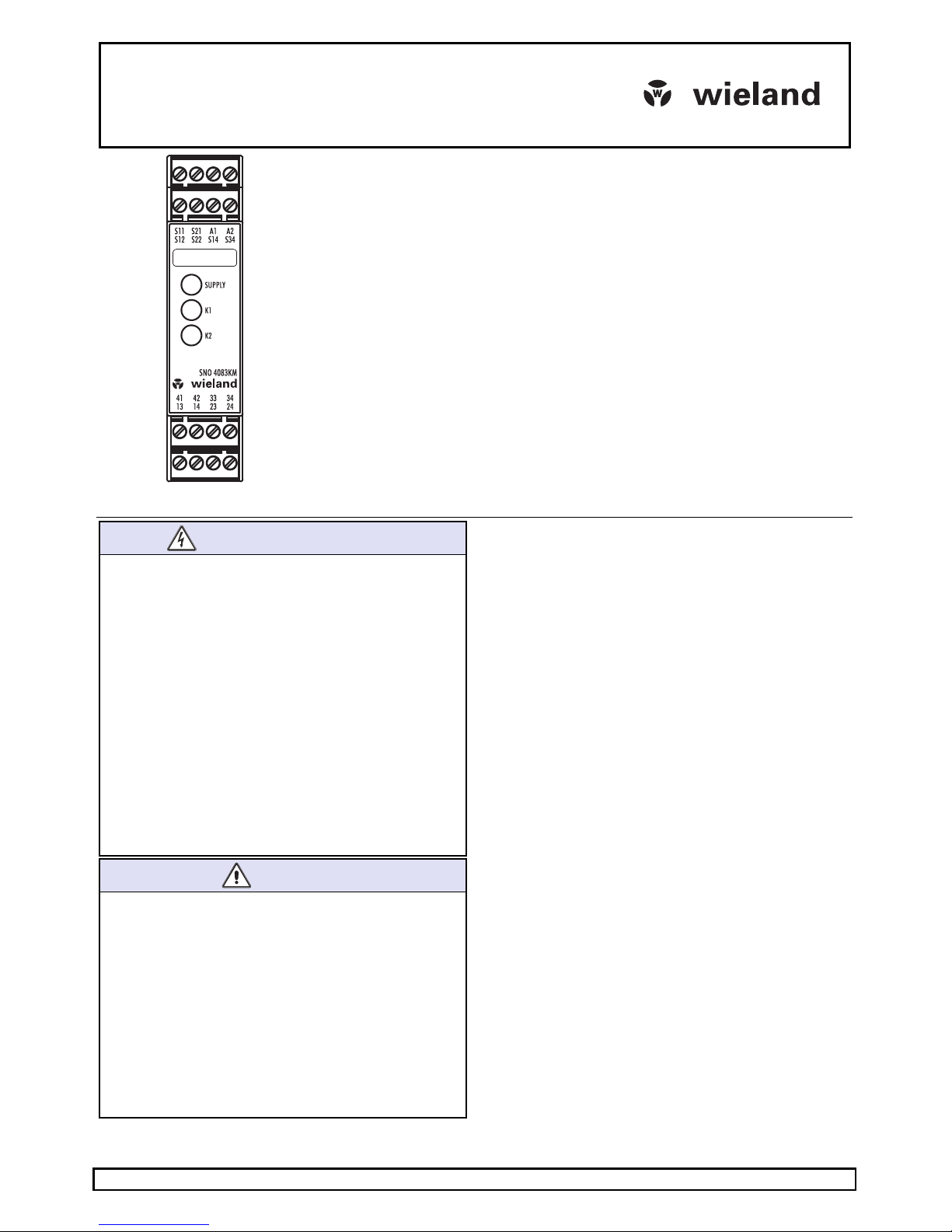
SNO 4083KM
Wieland Electric GmbH
Brennerstraße 10-14
D-96052 Bamberg
Tel. +49 (0) 951 / 9324 -0
Fax +49 (0) 951 / 9324 -198
www.wieland-electric.com
Doc. # BA000773 – 11/2014 (Rev. H) SNO 4083KM DE 1
Basisgerät für Not-Aus- und Schutztür-Anwendungen
• Basisgerät nach EN 60204-1:2007 und EN ISO 13849-1:2007 für ein- oder zweikana-
lige Not-Aus-Überwachung.
• PL e / Kategorie 4 nach EN ISO 13849-1:2007
• SILCL 3 nach DIN EN 62061:2005
• Stop-Kategorie 0 gemäß EN 60204-1
• Manueller oder automatischer Start
• Mit / ohne Querschlusserkennung
• Rückführkreis zur Überwachung externer Schütze
• Drei Freigabestrompfade, ein Meldestrompfad
• Auswerteeinheit für BWS Typ 4 gemäß EN 61496-1
• Einsatz nach EN 81-1 und EN 50156-1
• Zur Nachschaltung an eine Schaltmatte gemäß EN 1760-1
Geräteausführungen
SNO 4083KM-A DC 24 V mit Schraubklemmen, steckbar
SNO 4083KM-A AC 115-230 V mit Schraubklemmen, steckbar
SNO 4083KM-C DC 24 V mit Federkraftklemmen, steckbar
SNO 4083KM-C AC 115-230 V mit Federkraftklemmen, steckbar
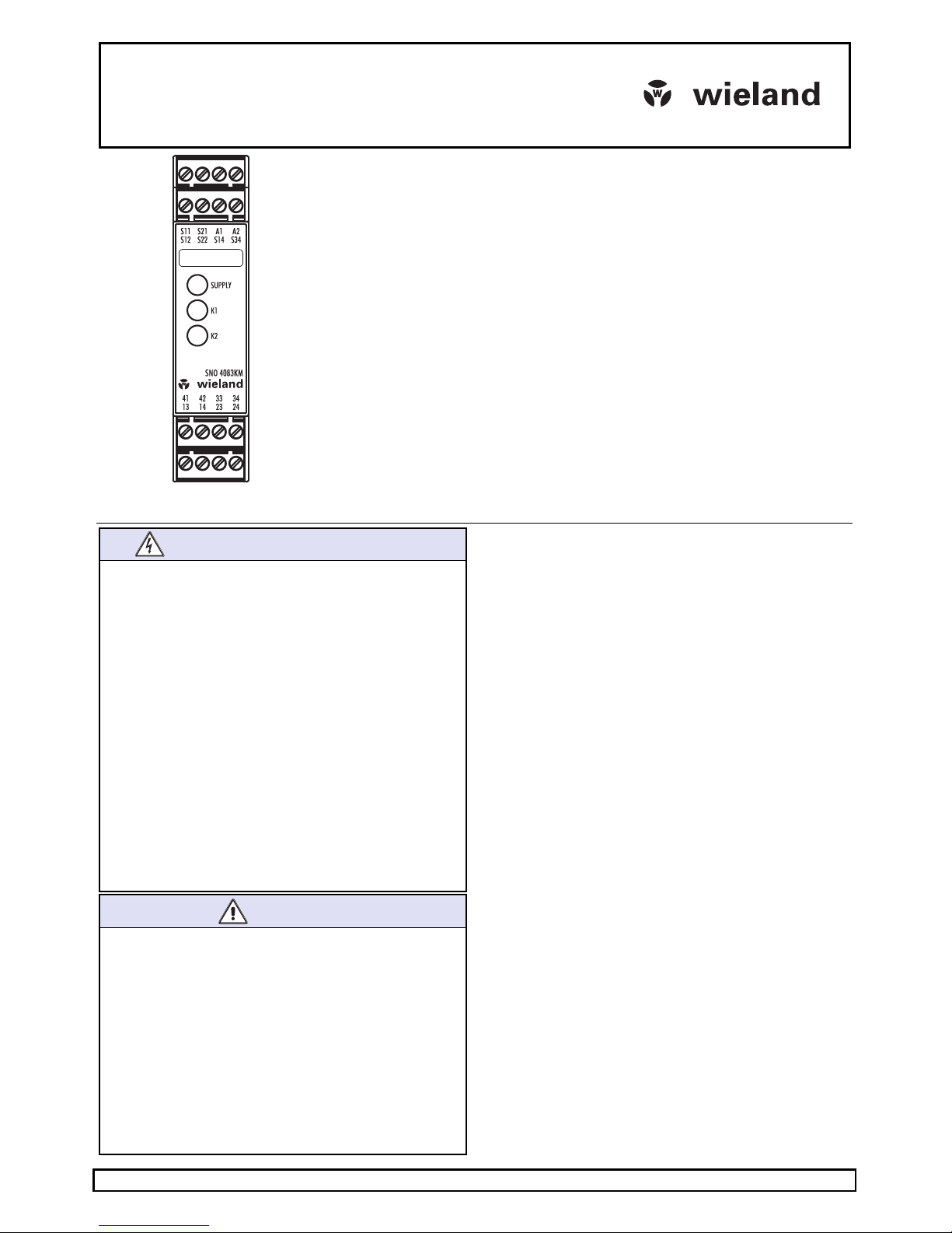
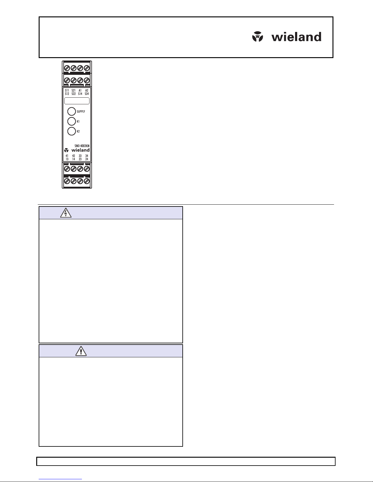
Frontansicht
Supply LED grün Betriebsspannungsanzeige
K1, K2 LED grün Betriebs- und Statusanzeige der Relais K1, K2 und der
Sicherheitskreise
SI CHE RHE IT S BE STI MMU NGE N
•
Die Montage, Inbetriebnahme, Änderung und Nachrüstung
darf nur von einer Elektrofachkraft ausgeführt werden!
• Schalten Sie das Gerät / die Anlage vor Beginn der Arbeiten
spannungsfrei! Bei Installations- und Anlagenfehlern kann
bei nicht galvanisch getrennten Geräten auf dem Steuerkreis Netzpotential anliegen!
• Beachten Sie für die Installation der Geräte die Sicherheits-
vorschriften der Elektrotechnik und der Berufsgenossenschaft.
• Durch Öffnen des Gehäuses oder sonstige Manipulation
erlischt jegliche Gewährleistung.
• Bei unsachgemäßen Gebrauch oder nicht bestimmungsge-
mäßer Verwendung darf das Gerät nicht mehr verwendet
werden und es erlischt jeglicher Gewährleistungsanspruch.
Nicht zulässige Einwirkungen können sein: starke mechanische Belastung des Gerätes, wie sie z.B. beim Herunterfallen auftritt, Spannungen, Ströme, Temperaturen, Feuchtigkeit außerhalb der Spezifikation.
• Bitte überprüfen Sie gemäß der geltenden Vorschriften bei
Erstinbetriebnahme Ihrer Maschine / Anlage immer alle
Sicherheitsfunktionen und beachten Sie die vorgegebenen
Prüfzyklen für Sicherheitseinrichtungen.
WA RNU NG
•
Führen Sie vor Beginn der Installation/ Montage oder
Demontage folgende Sicherheitsmaßnahmen durch:
1. Schalten Sie das Gerät / die Anlage vor Beginn der Arbei-
ten spannungsfrei!
2. Sichern Sie die Maschine / Anlage gegen Wiederein-
schalten!
3. Stellen Sie die Spannungsfreiheit fest!
4. Erden Sie die Phasen und schließen Sie diese kurz!
5. Decken und schranken Sie benachbarte, unter Spannung
stehende Teile ab!
6.
Der Einbau der Geräte muss in einem Schaltschrank mit
einer Schutzart von mindestens IP54 erfolgen.
• Eingeschränkter Berührungsschutz!
- Schutzart nach EN 60529: IP 20.
- Fingersicher nach EN 50274.
1 Bestimmungsgemäße Verwendung
Die Geräte sind Sicherheits-Schaltgeräte. Sie dürfen nur als Teil
von Schutzeinrichtungen an Maschinen zum Zweck des Personen-, Material-, Funktions- und Maschinenschutzes eingesetzt
werden.
2 Funktion
Das Gerät ist ein zweikanaliges, bei jedem EIN-AUS-Zyklus sich
selbst überwachendes Sicherheitsschaltgerät für Not-Aus-Einrichtungen nach EN 60204-1, welches mit zwangsgeführten
Relais ausgestattet ist. Das Gerät ist zur Nachschaltung an
kurzschlussbildenden Schaltmatten, Schaltleisten oder Schaltkanten in 4-Leiter-Technik (ohne Überwachungswiderstand)
geeignet.
Grundfunktion: Nach Anlegen der Versorgungsspannung an
die Klemmen A1 / A2 und geschlossenen Sicherheitseingängen
werden bei einem gültigen Resetsignal an S34 die Freigabestrompfade geschlossen. Beim Öffnen / Entregen der Sicherheitseingänge werden die Freigabestrompfade geöffnet.
Betriebsarten / Systemfunktionen
• Ein- oder zweikanalige Ansteuerung
• Mit oder ohne Querschlusserkennung
• Manueller Start (Triggerung mit fallender Flanke)
• Automatischer Start
• Auswertung äquivalent oder antivalent schaltender Signalge-
ber
Page 2
Doc. # BA000773 – 11/2014 (Rev. H) SNO 4083KM DE 2
HINW E I S E
•
Der Performance Level (PL) sowie die Sicherheits-Kategorie
nach EN ISO 13849-1 hängt von der Außenbeschaltung,
dem Einsatzfall, der Wahl der Befehlsgeber und deren örtlicher Anordnung an der Maschine ab.
• Der Anwender muss eine Risikobeurteilung nach
ISO 14121-1 durchführen.
•
Auf dieser Basis muss eine Validierung der Gesamtanlage /
-maschine nach den einschlägigen Normen durchgeführt
werden.
•
Der angegebene Performance-Level wird nur erreicht, wenn
je nach vorliegender Belastung des Gerätes (vergl. EN ISO
13849-1, Tab. C.1) und dem Anwendungsfall eine mittlere
Anzahl von Schaltzyklen pro Jahr nicht überschritten wird
(vergl. EN ISO 13849-1, C.2.3 und Tab. K.1). Mit einem
angenommenen B10d-Wert von 400.000 Schaltzyklen für
eine maximale Last ergibt sich z.B. eine maximale Zyklenzahl von 400.000 / (0,1 × 30) = 133.333 Schaltzyklen pro Jahr.
•
Die sicherheitstechnischen Kenngrößen gelten nur, wenn
die Relais mindestens einmal im Jahr geschaltet werden.
•
Das Betreiben des Gerätes außerhalb der Spezifikation kann
zu Funktionsstörungen oder zur Zerstörung des Gerätes
führen.
•
Vor der Inbetriebnahme, nach dem Austausch von Modulen
und / oder Änderungen an einer abgenommenen Installation
ist eine Überprüfung der ordnungsgemäßen Funktion
durchzuführen.
•
Bei Betrieb mit 115–230 V AC sind die Betriebsmittel der
Steuerkreise für eine Bemessungsspannung von 300 V
auszulegen. Basisisolierung zwischen Versorgungs- und
Steuerkreise.
•
Grundsätzlich sind beim Betrieb des Gerätes die angegebe-
nen Zeiten einzuhalten, ansonsten kann es zur Verriegelung
des Gerätes kommen. Die Verriegelung kann durch ordnungsgemäßes Öffnen der Sicherheitseingänge aufgehoben
werden.
HINW E I S E
•
Zur Vervielfältigung der Freigabestrompfade können die
Erweiterungsgeräte der Reihe SNE oder externe Schütze
mit zwangsgeführten Kontakten eingesetzt werden.
• Die Kontakte müssen mit maximal 6 A Betriebsklasse gG
abgesichert werden.
•
Die Steuerausgänge S11 und S21 sind mit einem Überlast-
schutz (bei Kurzschluss) ausgerüstet. Nach Beseitigung der
Störungsursache ist das Gerät nach ca. 3 s wieder betriebsbereit.
•
Die Steuerein- und ausgänge dienen ausschließlich dem
Anschluss von Befehlsgebern und nicht dem Anschluss
externer Verbraucher, wie z.B. Lampen, Relais oder Schützen.
•
Externe Lasten sind mit einer für die Last geeigneten
Schutzbeschaltung (z.B. RC-Glieder, Varistoren, Suppressoren u.ä.) auszurüsten, um elektrische Störungen zu mindern
und die Lebensdauer der Ausgangsschaltelemente zu erhöhen.
•
Für die Installation und dem Betrieb des Gerätes sind die
anwendungsspezifischen Normen zu berücksichtigen.
•
Bei externer Einspeisung der Eingänge S12 und S22, z.B.
über OSSD einer BWS (Installation 3), kann ein Abschalten
der Relais durch Unterbrechung oder Trennung der Versorgungsspannung an A1 nicht gewährleistet werden. Die
Relais schalten mit dem Öffnen der Sicherheitskreise ab.
• Die Sicherheitsfunktionen wurden durch UL nicht überprüft.
Die Zulassung ist nach den Anforderungen für allgemeine
Applikationen der UL508 erfolgt.
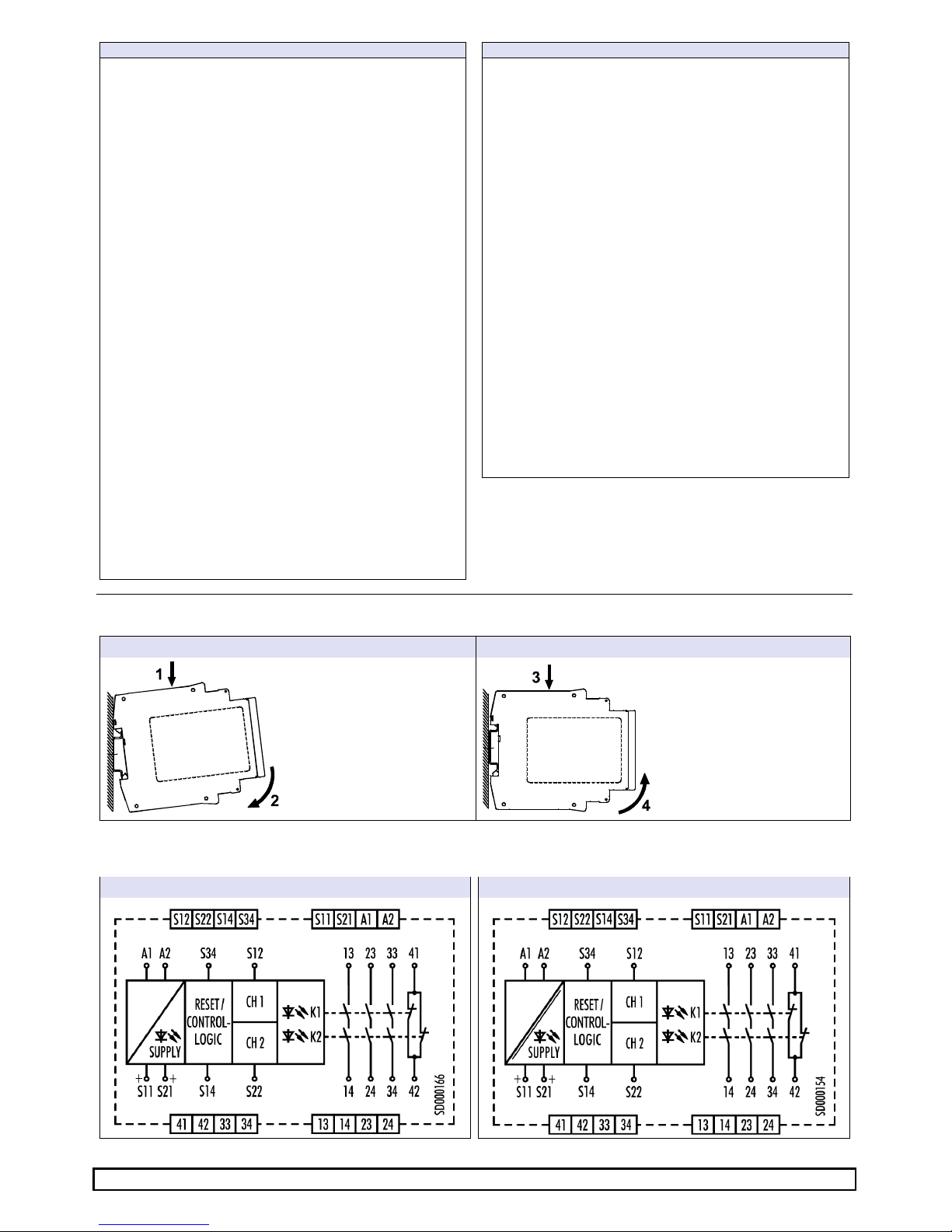
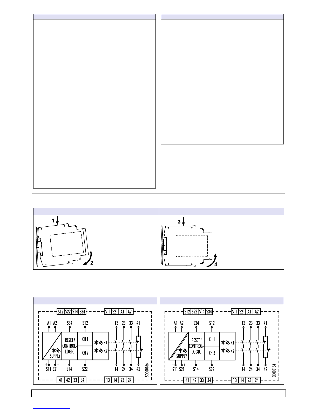
3 Montage
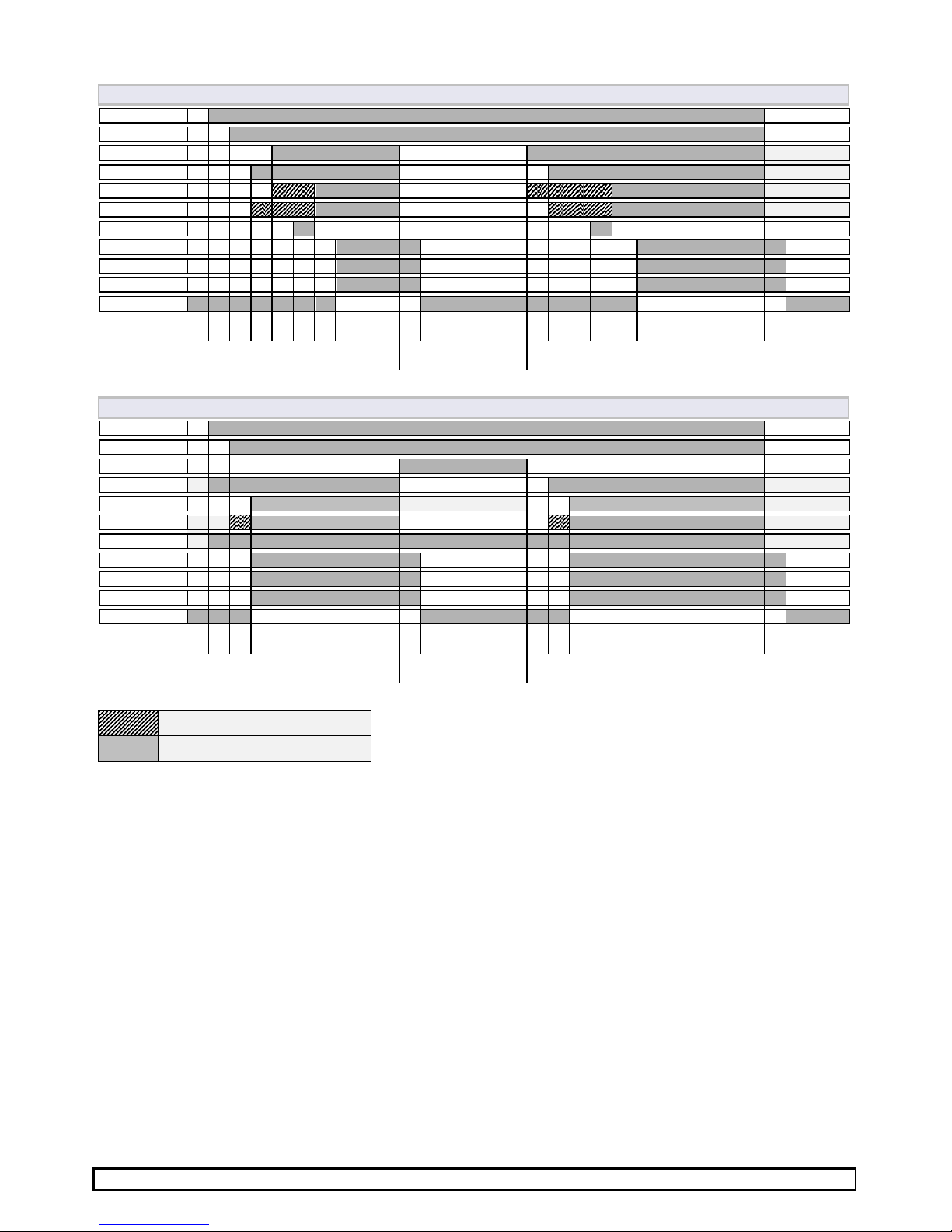
4 Klemmenschaltbilder
SNO 4083KM
… DC
24 V SNO 4083KM
… AC
115-230 V
Montage
Demontage
1.
Gerät auf die Hutschiene
einhängen
2.
Durch leichten Druck in
Pfeilrichtung Gerät auf die
Hutschiene aufschnappen.
3. Gerät in Pfeilrichtung herunterdrücken.
4. Im heruntergedrückten Zustand Gerät in Pfeilrich
tung
aus der Verrastung lösen
und von der Hut
schiene
nehmen.
Page 3
Doc. # BA000773 – 11/2014 (Rev. H) SNO 4083KM DE 3
5 Funktionsdiagramme
Äquivalente Ansteuerung mit manuellem Start (Installation 1, 2, 3, 4, 5, 8)
A1
S11
S12 (CH1)
S22 (CH2)
LED K1
LED K2
S34 (Reset)
13/14
23/24
33/34
41/42
t
B
tS t
BR
t
M
t
A
t
R1
tS tBR t
M
tA
t
R2
tW
Antivalente Ansteuerung mit automatischen Start (Installation 6, 7)
A1
S11
S12 (CH1)
S22 (CH2)
LED K1
LED K2
S34 (Reset)
13/14
23/24
33/34
41/42
t
B
tA
t
R1
tS tA
t
R2
tW
Hinweis:
LED blinkt
LED
leuchtet
perma
nent
Page 4
Doc. # BA000773 – 11/2014 (Rev. H) SNO 4083KM DE 4
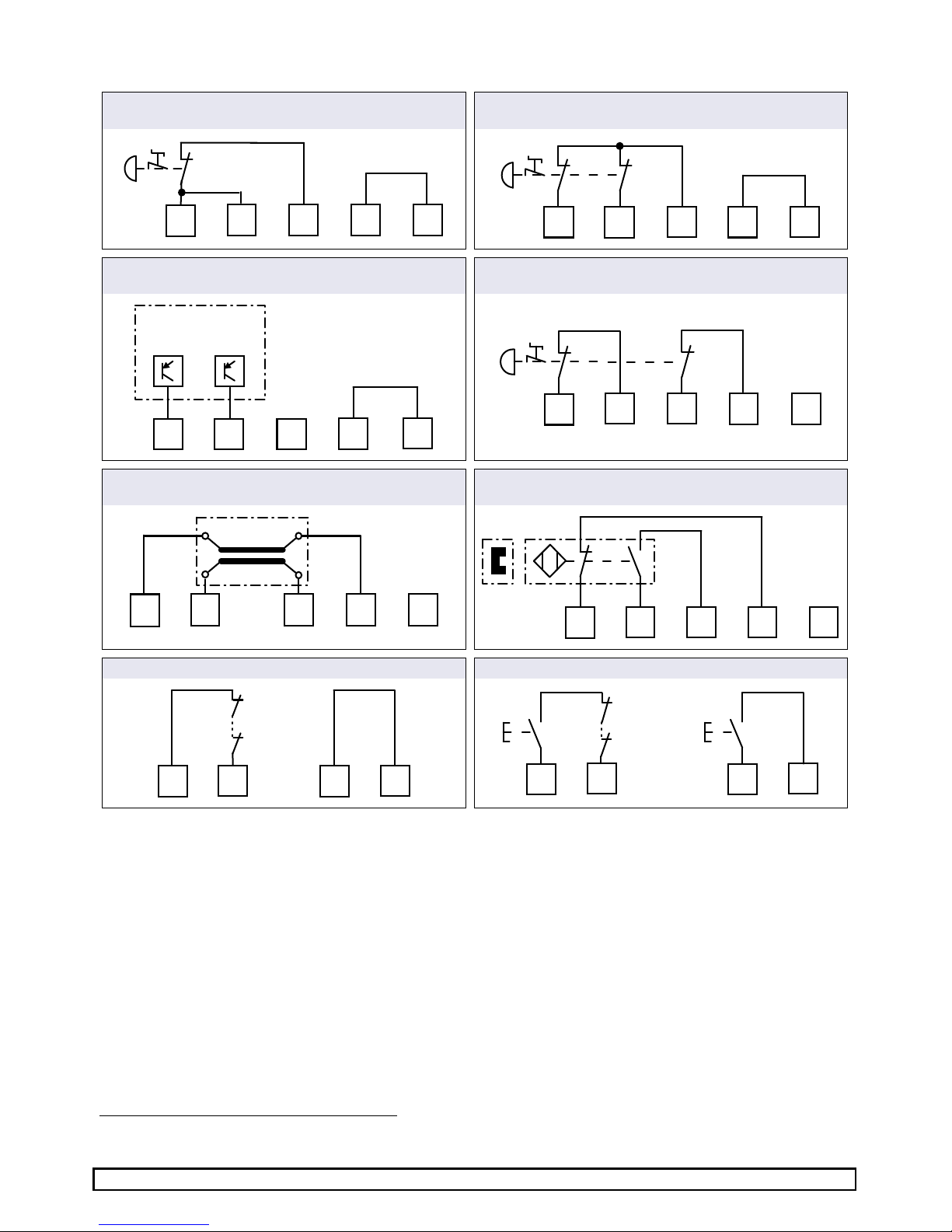
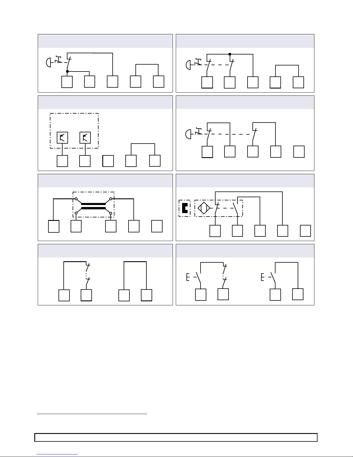
6 Installation
1 – Not-Aus-Taster, einkanalig 2 – Not-Aus-Taster, zweikanalig ohne
Querschlusserkennung
S12
S22 S21
S11 S14
S22
S12
S21
S11
S14
3 – Sicherheitslichtgitter BWS Typ 4, zweikanalig und
Querschlusserkennung durch die BWS1)
4 – Not-Aus Taster, zweikanalig mit
Querschlusserkennung
BWS type 4
with OSSD
S12
S22 S21 S11
S14
S11
S12 S21
S22 S14
5 – Schaltmatte, zweikanalig mit Querschlusserkennung
6 – Magnetschalter, zweikanalig antivalent mit
Querschlusserkennung
S11
S21 S22
S12 S14
Safety mat
S11
S21 S12
S22 S14
Type SMA
actuate d
7 – Reset, automatisch mit und ohne Rückführkreis
8 –
Reset, manuell überwacht mit und ohne Rückführkreis
S11
S34
K11 ... K13
S11
S34
S21
S34
K11 ... K13
S21
S34
1)
Diese Installationen sind für Geräte mit UB = 115-230 V AC nicht geeignet
Page 5
Doc. # BA000773 – 11/2014 (Rev. H) SNO 4083KM DE 5
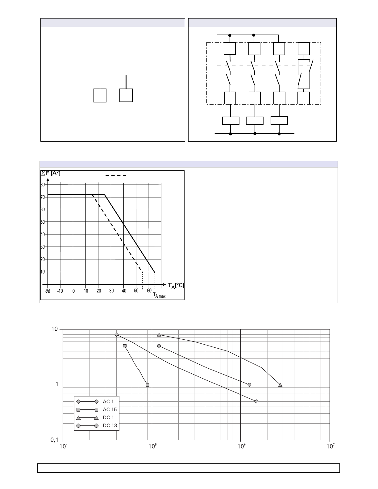
9 – Versorgung
10 – Ausgäng
e
A1
A2
L+ / L1 M / N
14
13
24
23
34
33
42
41
K1
K2
K11 K12
K13
L+/L1
M/N
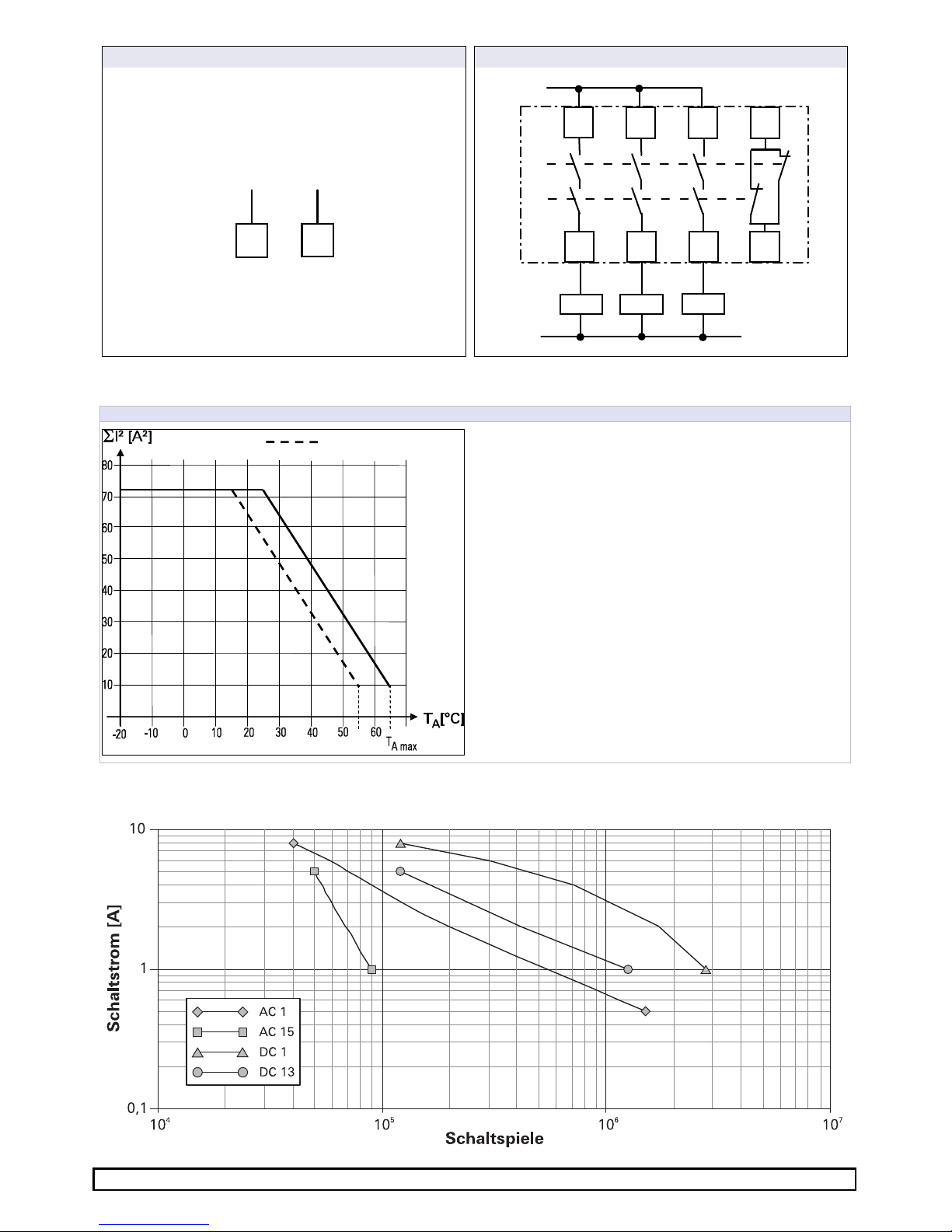
7 Kontaktlast-Derating
I² –
Summenstrom
8 Relais-Lebensdauer
UL508
Page 6
Doc. # BA000773 – 11/2014 (Rev. H) SNO 4083KM DE 6
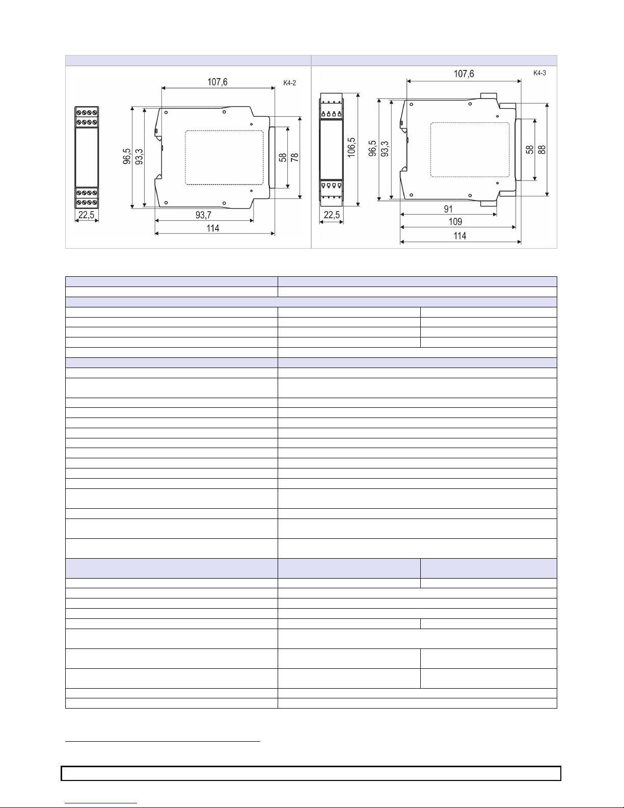
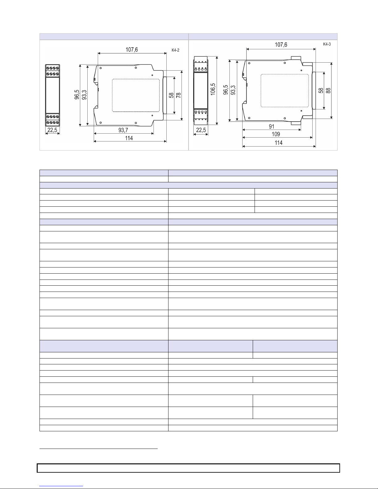
9 Abmessungen
SNO 4083KM
-
A Schraubklemme
SNO 4083KM
-
C Federkraftklemme
10 Technische Daten
Funktion
Not-Aus-Relais
Funktionsanzeige 3 LED, grün
Versorgungskreis
A1/A2
Nennspannung UN 24 V DC 115–230 V AC
Betriebsspannungsbereich UB: 0,85–1,2 × UN 20,4 bis 28,8 V DC 97 bis 253 V AC
Bemessungsleistung 1,6 W 1,8 W / 4,0 VA
Nennfrequenz 50–60 Hz
Bereitschaftszeit t
B
max. 1,2 s
Steuerkreise
Eingangsspannung 19,2 … 28,8 V DC
Eingangsstrom (typ./max.) S12 / S22
S14 / S34
25 / 100 mA
3 / 5 mA
Ansprechzeit tA 250 ms
Mindesteinschaltdauer tM (manueller Start, min./max.) 125 ms / 5 s
Bereitschaftszeit für Reset tBR > 4 ms
Wiederbereitschaftszeit tW 120 ms
Rückfallzeit t
R
1
(typ. / max.) 12 / 35 ms
Rückfallzeit t
R2
bei Abfall A1 max. 200 ms
Synchronzeitüberwachung tS siehe Typenschild
Testpuls S11 (Länge / Intervall) 4 ms / 200 ms
Testpuls S12, S22: Länge / Intervall (Installation 3) < 0,8 ms / > 5,5 ms
Testpulsverhältnis S12, S22: Länge / Intervall (Installation 3)
< 7 %
Testpulslänge tTR, des eingehenden Testpulses < 16 ms
Verzögerungszeit tD (zeitlicher Versatz zwischen
Testpuls und eingehendem Testpuls)
< 48 ms
Max. Leitungswiderstand pro Kanal
2
)
24 V DC (5 + ((1,176 × UB / 24 V) – 1) × 200) Ω
115–230 V AC 12 Ω
Ausgangskreise
Freigabestrompfade
13/14, 23/24, 33/34
Meldestrompfade
41/42
Kontakt Schließer Öffner
Kontaktart zwangsgeführt
Kontaktwerkstoff AG-Legierung, vergoldet
Schaltnennspannung U 230 V AC
Max. thermischer Dauerstrom
ITH 6 A 2 A
Max. Summentrom I
N
2
55 °C 25 A
2
(UL 508: 9 A2)
65 °C 9 A2
Gebrauchskategorie AC-15 Ue 230 V, Ie 5 A
DC-13 Ue 24 V, Ie 5 A
Kurzschlussschutz Schmelzsicherung 6 A Klasse gG,
Schmelzintegral < 100 A²s
Bedingter Kurzschlußstrom 1000 A
Mechanische Lebensdauer 10 x 106 Schaltspiele
2)
Werden 2-kanalige Geräte einkanalig eingesetzt, dann halbiert sich der Wert.
Page 7

Doc. # BA000773 – 11/2014 (Rev. H) SNO 4083KM DE 7
Klemmen
- und Anschlussdaten
Schraubklemmen
Federkraftklemmen
(TWIN)
Eindrähtig oder feindrähtig 1 x 0,2 mm² bis 2,5 mm²
2 x 0,2 mm² bis 1,0 mm²
1 x 0,2 mm² bis 1,5 mm²
Feindrähtig mit Aderendhülse nach DIN 46228 1 x 0,25 mm² bis 2,5 mm²
2 x 0,25 mm² bis 1,0 mm²
1 x 0,25 mm² bis 1,5 mm²
Leitergröße AWG (nur Cu-Leitungen verwenden) 26–14 24–16
Maximales Anzugsdrehmoment 0,5 bis 0,6 Nm (5-7 lbf-in)
Abisolierlänge 7 mm
Allgemeine Daten
Luft- und Kriechstrecken zwischen den Stromkreisen EN 60664-1
Ausgangskreise 1 13/14 und 23/24
Ausgangskreise 2 33/34 und 41/42
Versorgungskreis A1/A2
Steuerkreise S11, S12, S21, S22, S14 und S34
Sichere Trennung
– Bemessungsspannung 300 V
– Überspannungskategorie IV (6kV)
Ausgangskreise 1 - Ausgangskreise 2
Ausgangskreise 1 und 2 - Versorgungskreis
Ausgangskreise 1 und 2 - Steuerkreise
Basisisolierung
– Bemessungsspannung 300 V
– Überspannungskategorie III (4kV)
Ausgangskreise 1
Ausgangskreise 2
Versorgungskreis - Steuerkreise (nur bei 115-230 V AC)
Schutzart nach EN 60529 Gehäuse / Klemmen IP40 / IP20
Betriebsumgebungstemperatur –25 bis +65 °C (UL508: -25 bis +55°C)
Lagertemperatur –25 bis +75 °C
Gewicht 0,2 kg
Normen EN ISO 13849-1, EN 62061, EN 81-1, EN 50156-1
Zulassungen TÜV, cULus
11 Fehlercodes und Fehlerbehebung
Blinkcode (SUPPLY
-
LED)
2
Querschluss, behebbar durch Beseitigung des Querschlusses im laufenden Betrieb
3
Ablauffehler, Verletzung der korrekten Abfolge bei zweikanaliger Ansteuerung, behebbar im laufenden Betrieb
durch erneute korrekte Betätigungsabfolge
4
Synchronzeitfehler, Überschreitung der Synchronzeit bei zweikanaliger Ansteuerung, behebbar im laufenden
Betrieb durch Einhaltung der Synchronzeit
5
Überschreitung der maximalen Reset-Betätigungsdauer, behebbar im laufenden Betrieb durch erneute ResetBetätigung mit korrekter Dauer
6
Konfigurationsfehler, behebbar durch Anlegen der korrekten Klemmenbelegung für die gewünschte Konfiguration, Gerät aus/einschalten erforderlich
7
Unter- / Überschreitung der zulässigen Eingangsspannungsgrenzen an S12 und S22, behebbar durch korrektes
Einstellen der Versorgungsspannung, Gerät aus/einschalten erforderlich
8
Temperatur im Gerät zu hoch, behebbar durch Verringerung der Kontaktlasten oder der Umgebungstemperatur,
Gerät aus/einschalten erforderlich
≥
12
Internes Überwachungsereignis, bitte tauschen Sie das Gerät aus und kontaktieren Sie den Kundendienst
Sollte ein Fehler auch nach der Beseitigung der Ursache weiterhin angezeigt werden, dann müssen die Eingänge S12, S22, S14
und S34 bei Power-on offen gehalten werden (z.B durch Abziehen des Steckers). Der Fehler sollte dann gelöscht sein und es
kann mit der gewünschten Installation durch Power-off und Power-on neu gestartet werden.
Page 8
Instructions
(Translation of the original instructions)
SNO 4083KM
Wieland Electric GmbH
Brennerstraße 10-14
D-96052 Bamberg
Tel. +49 (0) 951 / 9324 -0
Fax +49 (0) 951 / 9324 -198
www.wieland-electric.com
Doc. # BA000773 – 11/2014 (Rev. H) SNO 4083KM EN 8
Basic device for EMERGENCY STOP and safety door applications
• Basic device according to EN 60204-1:2007 and EN ISO 13849-1:2007 for single or
two-channel EMERGENCY STOP monitoring.
• PL e / category 4 according to EN ISO 13849-1:2007
• SILCL 3 according to DIN EN 62061:2005
• Stop category 0 according to DIN EN 60204-1
• Manual or automatic start
• With / without crossover detection
• Feedback circuit for monitoring external contactors
• Three enabling current paths, one messaging current path
• Evaluation unit for BWS 4 according to EN 61496-1
• Usage according to EN 81-1 and EN 50156-1
• For connection in series with a pressure sensitive mat according to EN 1760-1
Device versions
SNO 4083KM-A DC 24 with screw terminals, pluggable
SNO 4083KM-A AC 115-230 V with screw terminals, pluggable
SNO 4083KM-C DC 24 V with spring-loaded terminals, pluggable
SNO 4083KM-C AC 115-230 V with spring-loaded terminals, pluggable
Front view
Supply LED green, power supply indicator
K1, K2 LED green operating and status display for relays K1, K2 and the
safety circuits.
SA FET Y R EGU LA TIO NS
•
Installation, commissioning, modification and retrofitting
must only be performed by a qualified electrician.
• Disconnect the device / the system from the power supply
before starting work. In the case of installation and system
errors, mains voltage can be present on the control circuit in
the case of non-galvanically isolated devices.
• Observe the electrotechnical and professional trade associa-
tion safety regulations for installation of the equipment.
• Opening the case or other manipulation voids any war-
ranty.
• In the case of improper use or any use other than for the
intended purpose, the device must no longer be used and
any warranty claim is void. Invalidating causes can be:
strong mechanical loading of the device, such as occur
when falling or voltages, currents, temperatures, humidity
outside the specifications.
• Always check all safety functions in accordance with the
applicable regulations during initial commissioning of your
machine / system and observe the specified inspection
cycles for safety devices.
WA RNI NG
•
Take the following safety precautions before starting
installation / assembly or dismantling:
1. Disconnec
t the device / the system from the power
supply before starting work.
2. Secure the machine / system against being switched on
again.
3. Confirm that no voltage is present.
4. Ground the phases and short to ground briefly.
5. Cover and shield neighbouring live parts.
6. The devices must be installed in a switch cabinet with a
protection class of at least IP54.
• Limited contact protection! Protection class according to
EN 60529:
− Case / terminals: IP40 / IP20.
− Finger-proof according to EN 50274.
1 Proper use
The devices are safety switching devices. They must only be
used as components of safety equipment on machines that is
intended for the protection of persons, material, functions and
machinery.
2 Function
The device is a two-channel safety switching device for EMERGENCY STOP equipment according to EN 60204-1. It performs
self-monitoring during each ON-OFF cycle and is equipped with
positively driven relays. The device is suitable for connection in
series with short-circuiting pressure sensitive mats, pressure
sensitive bumpers or switching edges with 4-wire technology
(without a monitoring resistor).
Basic function: After applying the supply voltage to the
terminals A1/A2 and closed safety inputs, the enabling current
paths are closed when a valid reset signal is established at S34.
The enabling current paths are opened when the safety inputs
are opened / de-energized.
Operating modes / System functions
• Single-channel or two-channel actuation
• With or without crossover detection
• Manual start (triggering with falling edge)
• Automatic start
• Evaluation of signal transmitters featuring equivalent or non-
equivalent switching
Page 9
Doc. # BA000773 – 11/2014 (Rev. H) SNO 4083KM EN 9
NOTE
•
The performance level (PL) and safety category in accord-
ance with EN ISO 13849-1 depend on the external wiring,
the application case, the choice of control device and how
this is physically arranged on the machine.
• The user must carry out a risk assessment in accordance
with ISO 14121-1.
• The entire system / machine must undergo validation in
accordance with the applicable standards on the basis of this.
• The stated performance level will only be achieved if, taking
into account the prevailing device load (see EN ISO 13849-1
Table C.1) and the application case, an average number of
switching cycles per year is not exceeded (see EN ISO
13849-1, C.2.3 and Table K.1). Assuming that the B10d
value is 400,000 for the maximum load, the maximum cycle
number would be 400,000 / 0.1 x 30 = 133,333 switching
cycles per year.
•
The safety-related characteristics only apply when the relays
are switched at least once per year.
•
Operating the device other than specified can result in
malfunctions or destruction of the device.
•
The device must be checked to ensure it is in perfect
working order before commissioning, after replacement of
modules and/or in the case of changes to an installation that
has already undergone acceptance.
•
For operation at 115–230 V AC, the operating equipment of
the control circuits must be designed for a rated voltage of
300 V. Basic isolation between supply and control circuits.
•
The specified times must always be adhered to when
operating the device; otherwise, the device may become
locked. Locking may be reversed by opening the safety
inputs in the proper manner.
•
The expansion units of the SNE series or external contactors
with positively-driven contacts can be used for duplicating
the enabling current paths
NOTE
•
The contacts must be fused with maximum 6 A operating
class gG.
•
Control outputs S11 and S21 are equipped with overload
protection (for short circuits). Once the cause of the error
has been rectified, the device is ready for operation again
after approx. 3 s.
•
The control inputs and outputs are only used for the con-
nection of control devices and not for the connection of
external consumers such as lamps, relays or contactors.
•
External loads must be equipped with a suitable protection
circuit for the load (e.g. RC elements, varistors, suppressors,
etc.) in order to reduce electromagnetic interference and
increase the service life of the output switching elements.
•
The application-specific standards must be observed when
installing and operating the device.
•
In the case of an external incoming supply for inputs S12
and S22 (e.g. via the OSSD of electrosensitive protective
equipment (installation 3) there is no assurance that the
relays can be deactivated by interrupting or isolating the
supply voltage at A1 / A2. The relays are deactivated when
the safety circuits are opened.
• The safety functions have not been checked by UL. The
certification process has been carried out in accordance
with the requirements for general applications as stipulated
by UL508.
3 Mounting
4 Terminal diagram
SNO 4083KM… DC 24 V
SNO 4083KM
… AC
115-230 V
Mounting
Dismantling
1.
Attach the device to the DIN
rail.
2.
Snap the device on to the
DIN rail by applying slight
pressure in the direction of
the arrow.
3. Press the
device down in
the direction of the arrow.
4.
While pressed down,
detach the device from the
latching (in the direction
indicated by the arrow) and
remove it from the DIN rail.
Page 10

Doc. # BA000773 – 11/2014 (Rev. H) SNO 4083KM EN 10
5 Function diagrams
Equivalent actuation with manual start (installation 1, 2, 3, 4, 5, 8)
A1
S11
S12 (CH1)
S22 (CH2)
LED K1
LED K2
S34 (Reset)
13/14
23/24
33/34
41/42
t
B
tS t
BR
t
M
t
A
t
R1
tS tBR t
M
tA
t
R2
tW
Non-equivalent actuation with automatic start (installation 6, 7)
A1
S11
S12 (CH1)
S22 (CH2)
LED K1
LED K2
S34 (Reset)
13/14
23/24
33/34
41/42
t
B
tA
t
R1
tS tA
t
R2
tW
Notice:
LED blinking
LED permanently lit
Page 11
Doc. # BA000773 – 11/2014 (Rev. H) SNO 4083KM EN 11
6 Installation
1 – EMERGENCY STOP button, single-channel 2 – EMERGENCY STOP button, two-channel without
crossover detection
S12
S22 S21
S11 S14
S22
S12
S21
S11
S14
3 – Safety light curtain BWS type 4, two
-
channel with
crossover detection by BWS1)
4 – EMERGENCY STOP button, two
-
channel with
crossover detection
BWS type 4
with OSSD
S12
S22 S21 S11
S14
S11
S12 S21
S22 S14
5 – Pressure sensitive mat, two
-
channe
l with crossover
detection
6 – Solenoid switch, two
-
channel, non
-
equivalent, with
crossover detection
S11
S21 S22
S12 S14
Safety mat
S11
S21 S12
S22 S14
Type SMA
actuate d
7 – Reset, automatic, with and without feedback circuit
8 – Reset, manual, monitored, with and without
feedback
circuit
S11
S34
K11 ... K13
S11
S34
S21
S34
K11 ... K13
S21
S34
1 )
These installation types are not suitable for devices where UB = 115-230 V AC.
Page 12
Doc. # BA000773 – 11/2014 (Rev. H) SNO 4083KM EN 12
9 – Power supply
10 – Outputs
A1
A2
L+ / L1 M / N
14
13
24
23
34
33
42
41
K1
K2
K11 K12
K13
L+/L1
M/N
7 Contact load derating
I² –
Total current
8 Relay service life
UL508
Switching cycles
Page 13
Doc. # BA000773 – 11/2014 (Rev. H) SNO 4083KM EN 13
9 Dimensions
SNO 4083KM
-
A screw terminal
SNO 4083KM
-
C spring
-
loaded terminal
10 Technical data
Function
EMERGENCY STOP relay
Function indicator 3 LEDs, green
Power circuit
Rated voltage UN 24 V DC 115–230 V AC
Operating voltage range UB: 0.85–1.2 × UN 20.4 to 28.8 V DC 97 to 253 V AC
Rated power 1.6 W 1.8 W / 4.0 VA
Nominal frequency 50-60 Hz
Standby time 1.2 s max.
Control circuits
Input voltage 19.2 to 28.8 V DC
Input current (typ. / max.) S12/S22
S14/S34
25 / 100 mA
3 / 5 mA
Response time (manual start tA1, autom. start tA2) 250 ms
Minimum activation time tM (manual start, min. /
max.)
125 ms / 5 s
Standby time for reset tBR > 4 ms
Recovery time tW 120 ms
Release time tR (typ. / max.) 12 / 35 ms
Synchronous time monitoring tS 1.5 s / 0.5 s (SNO 4083KM-A 0,5S)
Test pulse S11: length / interval 4 ms / 200 ms
Test pulse S12, S22: length / interval (Installation 3) < 0.8 ms / > 5.5 ms
Test pulse ratio S12, S22: length / interval (Installation
3)
< 7 %
Test pulse length tTR, of the incoming test pulse < 16 ms
Delay time tD (time between test pulse and incoming
test pulse)
< 48 ms
Max. line resistance per channel
2
)
24 V DC (5 + ((1.176 × UB / 24 V) – 1) × 200) Ω
115–230 V AC 12 Ω
Output circuits
Enabling current paths
13/14, 23/24, 33/34
Messaging current paths
41/42
Contact Normally open Normally closed
Contact type Positively driven
Contact material Ag alloy, gold plated
Rated switching voltage U 230 V AC
Max. thermal permanent current
ITH 6 A 2 A
Max. total current I
N
2
55°C 25 A
2
(UL 508: 9 A2)
65°C 9 A2
Utilisation category AC-15 Ue 230 V, Ie 5 A
DC-13 Ue 24 V, Ie 5 A
Short circuit protection 6 A class gG fuse,
fuse integral < 100 A²s
Conditional short-circuit current 1000 A
Mechanical service life 107 switching cycles
2 )
If only one of the channels on a 2-channel device is used, the value is halved.
Page 14
Doc. # BA000773 – 11/2014 (Rev. H) SNO 4083KM EN 14
Terminals and connection data
Screw terminals
Spring
-
loaded ter
minals
(TWIN)
Single-core or finely stranded 1 x 0,2 mm² bis 2,5 mm²
2 x 0,2 mm² bis 1,0 mm²
1 x 0,2 mm² bis 1,5 mm²
Finely stranded with wire-end ferrule according to
DIN 46228
1 x 0,25 mm² bis 2,5 mm²
2 x 0,25 mm² bis 1,0 mm²
1 x 0,25 mm² bis 1,5 mm²
AWG conductor size (only use Cu wires) 26–14 24–16
Maximum tightening torque 0,5 bis 0,6 Nm (5-7 lbf-in)
Stripping length 7 mm
General data
Air gap and creepage paths between the circuits EN 60664-1
Output circuits 1 13/14 and 23/24
Output circuits 2 33/34 and 41/42
Power circuit A1/A2
Control circuits S11, S12, S21, S22, S14 and S34
Safety separation
– Rated voltage 300 V
– Overvoltage category IV (6kV)
Output circuits 1 — Output circuits 2
Output circuits 1 and 2— Power circuit
Output circuits 1 and 2— Control circuits
Basic insulation
– Rated voltage 300 V
– Overvoltage category III (4kV)
Output circuits 1
Output circuits 2
Power circuit — Control circuits (only 115-230 V AC)
Protection class according to EN 60529
case/terminals
IP40 / IP20
Ambient operating temperature –25 to +65 °C (UL508: -25 to +55°C)
Storage temperature –25 to +75 °C
Weight 0.2 kg
Standards EN ISO 13849-1, EN 62061, EN 81-1, EN 50156-1
Certifications TÜV, cULus
11 Error codes and correction
Flashing code
(SUPPLY
-LED)
2
Crossover, can be rectified during operation
3
Process error, failure to observe the correct sequence for two-channel actuation, can be rectified during operation by repeating the actuation sequence correctly
4
Synchronous time error, synchronous time exceeded in the case of two-channel actuation, can be rectified
during operation by adhering to the synchronous time
5
Maximum reset actuating time exceeded, can be rectified during operation by repeating the reset with the
correct time
6
Configuration error, can be rectified by ensuring the correct terminal assignment for the required configuration,
the device has to be switched off and on again
7
Permissible input voltage limits undershot / overshot at S12 and S22, can be rectified by setting the correct
supply voltage, the device has to be switched off and on again
8
Device temperature too high, can be rectified by reducing the contact loads or the ambient temperature, the
device has to be switched off and on again
≥
12
Internal monitoring event, please replace the device and contact after sales service
If an error is still indicated even after the cause has been rectified, inputs S12, S22, S14 and S34 must be kept open during
power-on (e.g. pull out the connector). The error should then be cleared and you can perform a restart with the required installation by means of a power-off and power-on operation.
Page 15
Notice d’instructions
(traduction de la notice originale)
SNO 4083KM
Wieland Electric GmbH
Brennerstraße 10-14
D-96052 Bamberg
Tel. +49 (0) 951 / 9324 -0
Fax +49 (0) 951 / 9324 -198
www.wieland-electric.com
Doc. # BA000773 – 11/2014 (Rev. H) SNO 4083KM FR 15
Module de base pour applications de porte d'arrêt d'urgence et de porte de protection
• Appareil de base selon les normes EN 60204-1:2007 et EN ISO 13849-1:2007 pour une surveil-
lance d'arrêt d'urgence monocanal ou bi-canal
• PL e / Catégorie 4 selon la norme EN ISO 13849-1:2007
• SILCL 3 selon la norme DIN EN 62061:2005
• Catégorie d'arrêt 0 selon la norme EN 60204-1
• Démarrage manuel ou automatique
• Avec / sans détection de court-circuit transversal
• Boucle de retour pour la surveillance des contacteurs-disjoncteurs externes
• 3 trajets du courant de validation, 1 trajet du courant de signalisation
• Unité d'évaluation pour BWS 4 selon EN 61496-1
• Utilisation selon EN 81-1 et EN 50156-1
• Pour une connexion à la suite d'un tapis sensible selon EN 1760-1
Versions des appareils
SNO 4083KM-A DC 24 V avec bornes à vis, enfichables
SNO 4083KM-A AC 115-230 V avec bornes à vis, enfichables
SNO 4083KM-C DC 24 V avec bornes à ressort, enfichables
SNO 4083KM-C AC 115-230 V avec bornes à ressort, enfichables
Vue de face
Supply LED verte pour l'affichage de la tension de service
K1, K2 LED verte pour l'affichage de fonctionnement et d'état des relais K1, K2 et des
circuits de sécurité.
CO NSI GNE S D E S ÉC U RI TÉ
•
Seul un électricien qualifié est habilité à effectuer le montage, la
mise en service, la modification et le rééqui-pement !
• Avant de commencer les travaux, mettre l'appareil/l'installation
hors tension! En cas de défauts de montage et de l'installation,
avec les modules non séparés galvaniquement, le circuit de
commande peut être sous potentiel réseau !
• Pour l'installation des modules, veuillez observer les consignes de
sécurité en matière d'électronique et celles de la caisse professionnelle d'assurance-accidents.
• L'ouverture de l'appareil ou toute autre manipulation entraîne
l'extinction de la garantie.
• En cas d'utilisation incorrecte ou d'utilisation non confor-me à
l'usage prévu, le module ne doit plus être utilisé et tout droit à la
garantie est annulé. Exemples d'effets inad-missibles : Forte
sollicitation mécanique du module, com-me p. ex. en cas de
chute, de tensions, de courants, de températures, d'humidité
hors spécification.
• Lors de la première mise en service de votre machine / installa-
tion, veillez à vérifier systématiquement que toutes les fonctions
de sécurité sont conformes aux pres-criptions applicables et
observez les cycles de contrôle préconisés pour les dispositifs de
sécurité.
AV ERT ISS EME NT
•
Avant de procéder à l'installation, au montage ou au démontage,
veuillez appliquer les mesures de sécurité suivantes :
1. Avant de commencer les travaux, mettre le
module/l'installation hors tension !
2. Protéger la machine /l'installation contre toute remise en
marche intempestive !
3. S'assurer de l'absence de tension !
4. Mettre les phases à la terre et les court-circuiter !
5. Recouvrir et isoler les parties sous tension voisines !
6. Le montage des modules doit s'effectuer dans une armoire de
commande possédant un indice de protection minimal
d'IP 54.
•
Protection limitée contre les contacts accidentels !
Indice de protection conforme à la norme EN 60529.
− Boîtier / bornes : IP 40 / IP 20.
− Protection des doigts selon la norme EN 50274.
1 Utilisation conforme à l'usage
prévu
Les modules sont des modules de coupure de sécurité. Ils ne
doivent être mis en œuvre qu'en tant qu'élément de dispositifs
de protection sur des machines et sont dédiés à la protection
des personnes, du matériel, des fonctions et des machines.
2 Fonction
Le module est un module de coupure de sécurité bi-canal,
autocontrôlé pour chaque cycle de MARCHE-ARRÊT pour
dispositifs d'arrêt d'urgence selon la norme EN 60204-1, doté
de relais à commande forcée. Le modèle est conçu pour une
connexion à la suite de tapis sensibles, de barres ou de bords
sensibles à court-circuit en technique à 4 conducteurs (sans
résistance de surveillance).
Fonctionnement de base : Après application de la tension
d'alimentation aux bornes A1 / A2 et une fois les entrées de
sécurité fermées, les trajets du courant de validation sont
fermés dans le cas d'un signal de réinitialisation à S34. L'ouverture/la désexcitation des entrées de sécurité permet d'ouvrir les
trajets du courant de validation.
Modes de fonctionnement / Fonctions système
• Pilotage monocanal ou bi-canal
• Avec ou sans détection de court-circuit transversal
• Démarrage manuel (déclenchement avec front descendant)
• Démarrage automatique
• Évaluation de transmetteur de signaux à commutation en
phase ou en opposition de phase
Page 16

Doc. # BA000773 – 11/2014 (Rev. H) SNO 4083KM FR 16
REMARQ U E S
•
Le niveau de performance (« Performance Level », PL) et la
catégorie de sécurité selon la norme EN ISO 13849-1 dépendent du câblage extérieur, du cas d’application, du choix
du transmetteur d’ordres et de l’agencement sur la machine
sur place.
• L’utilisateur doit effectuer une évaluation du risque confor-
mément à la norme ISO 14121-1.
• Il convient de réaliser sur cette base une validation de
l’ensemble de l’installation / de la machine selon les normes
applicables.
• Le niveau de performance indiqué ne pourra être atteint,
selon la charge présente du module (cf. EN ISO 13849-1,
tab. C.1) et le cas d’application, que si un nombre moyen de
cycles de commutation par an n’est pas dépassé (cf. EN ISO
13849-1, C.20,3 et tab. K.1). Avec une valeur B10d donnée
de 400 000 cycles de commutation pour une charge maximale, on obtient par ex. un nombre maximal de cycles de
400 000 / (0,1 × 30) = 133 333 cycles de commutation par
an.
•
Les grandeurs caractéristiques de sécurité ne sont valables
que si les relais sont commutés au minimum une fois par
an.
•
L'exploitation du module en dehors de la spécification peut
entraîner des dysfonctionnements ou une destruction du
module.
•
Avant la mise en service, après le remplacement de mo-
dules et/ou en cas de modifications sur une installation déjà
réceptionnée, il faut procéder à une vérification du fonctionnement correct.
•
Lors d'un fonctionnement avec 115–230 V CA, les moyens
d'exploitation des circuits de commande et de signalisation
doivent être conçus de manière à supporter une tension
assignée de 300 V. Isolation de base entre d'une part le
circuit d'alimentation et d'autre part, le circuit de commande.
•
En principe, il convient de respecter les temps indiqués lors
du fonctionnement de l'appareil, sous peine de le verrouiller. L'ouverture conforme des entrées de sécurité permet
d'annuler le verrouillage de l'appareil.
REMARQ U E S
•
Pour la reproduction des trajets du courant de validation, il
est possible d'utiliser les modules d'extension de la gamme
SNE ou des contacteurs-disjoncteurs externes dotés de
contacts à commande forcée.
•
Les contacts doivent être protégés avec 6 A max. classe de
service gG.
•
Les sorties de commande S11 et S21 sont équipés d'un
système de protection contre les surcharges (en cas de
court-circuit). Une fois la cause du défaut éliminée, le module est à nouveau opérationnel après 3 s environ.
•
Les entrées et les sorties de commande servent exclusive-
ment au raccordement de transmetteurs d'ordres et non au
raccordement de consommateurs externes, comme par ex.
des lampes, des relais ou des contacteurs-disjoncteurs.
•
Les charges externes doivent être équipées d'un circuit de
protection adapté à la charge (par ex. circuits RC, varistances, suppresseurs, etc.) afin de réduire les perturbations
électriques et d'augmenter la durée de vie des modules de
coupure de sortie.
•
L'installation et l'exploitation de l'appareil requise la prise en
compte des normes spécifiques à l'application.
•
En cas d'injection externe au niveau des entrées S12 et S22,
par ex. via OSSD d'un dispositif de protection sans contact
(installation 3) une coupure des relais par interruption ou
coupure de la tension d'alimentation au niveau des bornes
A1/A2 ne peut pas être garantie. Les relais se coupent avec
l'ouverture des circuits de sécurité.
• Les fonctions de sécurité n'ont pas été contrôlées par la
norme UL. L'homologation est réalisée selon les exigences
relatives aux applications générales de la norme UL508.
3 Montage
4 Schéma de connexion des bornes
SNO 4083KM… DC 24 V
SNO 4083KM
… AC
115-230 V
Montage
Démontage
1.
Accrocher l'appareil sur le
profilé chapeau
2.
Enclencher l'appareil sur le
profilé chapeau en exerçant
une légère pression dans le
sens de la flèche.
3.
Abaisser l'appareil dans le
sens de la flèche.
4.
Désolidariser l'appareil
abaissé de son enclenche-
ment dans le sens de la
flèche et le retirer du profilé
chapeau.
Page 17

Doc. # BA000773 – 11/2014 (Rev. H) SNO 4083KM FR 17
5 Diagramme fonctionnel
Pilotage en phase avec démarrage manuel (installation 1, 2, 3, 4, 5, 8)
A1
S11
S12 (CH1)
S22 (CH2)
LED K1
LED K2
S34(Réinitialis
a
tion)
13/14
23/24
33/34
41/42
t
B
tS t
BR
t
M
tA
t
R1
tS tBR t
M
tA
t
R2
tW
Pilotage en opposition de phase avec démarrage automatique (installation 6, 7)
A1
S11
S12 (CH1)
S22 (CH2)
LED K1
LED K2
S34(Réinitialis
a
tion)
13/14
23/24
33/34
41/42
t
B
t
A
t
R1
tS t
A
t
R2
tW
Remarque :
LED clignotante
LED allumée en permanence
Page 18

Doc. # BA000773 – 11/2014 (Rev. H) SNO 4083KM FR 18
6 Installation
1 – Poussoir d'arrêt d'urgence, monocanal 2 – Poussoir d'arrêt d'urgence, bi-canal sans détection de
court-circuit transversal
S12
S22 S21
S11 S14
S22
S12
S21
S11
S14
3 – Grille lumineuse de sécurité BWS type
4, bi-canal et
détection de court-circuit transversal via BWS1)
4 – Poussoir d'arrêt d'urgence, bi
-
canal avec détection de
court-circuit transversal
BWS type 4
with OSSD
S12
S22 S21 S11
S14
S11
S12 S21
S22 S14
5 – Tapis sensible, bi
-
canal avec détection de court
-
circuit transversal
6 – Commutateur magnétique, bi
-
canal en opposition de
phase avec détection de court-circuit transversal
S11
S21 S22
S12 S14
Safety mat
S11
S21 S12
S22 S14
Type SMA
actuate d
7 – Réinitialisation, automatique avec et sans boucle de
retour
8 – Réinitialisation, manuelle surveillée avec et sans boucle
de retour
S11
S34
K11 ... K13
S11
S34
S21
S34
K11 ... K13
S21
S34
1 )
Ces installations ne sont pas adaptées aux appareils avec une tension UB = 115-230 V CA
Page 19

Doc. # BA000773 – 11/2014 (Rev. H) SNO 4083KM FR 19
9 – Alimentation
10 – S
orties
A1
A2
L+ / L1 M / N
14
13
24
23
34
33
42
41
K1
K2
K11 K12
K13
L+/L1
M/N
7 Réduction de la charge de contact
I² –
Courant cumulé
8 Durée de vie des relais
UL508
Manœuvres
Page 20

Doc. # BA000773 – 11/2014 (Rev. H) SNO 4083KM FR 20
9 Dimensions
Borne à vis SNO 4083KM
-A
Borne à ressort SNO 4083KM
-C
10 Caractéristiques techniques
Fonction
Relais d'arrêt d'urgence
Affichage des fonctions 3 LED, vertes
Circuit d'alimentation
Tension nominale UN 24 V CC 115–230 V CA
Plage de tension de service UB : 0,85–1,2 × UN 20,4 à 28,8 V CC 97 à 253 V CA
Puissance assignée 1,6 W 1,8 W / 4,0 VA
Fréquence nominale 50-60 Hz
Temps de disponibilité pour la fonction de réinitialisation
max. 1,2 s
Circuits de commande
Tension d’entrée 19,2 … 28,8 V DC
Courant d'entrée (type / max.) S12/S22
S14/S34
25 / 100 mA
3 / 5 mA
Temps de réponse
(démarrage manuel tA1, démarrage autom. tA2)
250 ms
Durée minimale d'activation tM
(démarrage manuel, min. / max.)
125 ms / 5
Temps de disponibilité pour la fonction de réinitialisation tBR
> 4 ms
Temps de réexcitation tW 120 ms
Temps de retombée tR (type / max.) 12 / 35 ms
Surveillance de synchronisation tS 1,5 s / 0,5 s (SNO 4083KM-A 0,5S)
D'impulsion test S11: longueur / intervalle 4 ms / 200 ms
D'impulsion test S12,S22: longueur / intervalle
(installation 3)
< 0,8 ms / > 5,5 ms
Rapport d'impulsion test S12, S22: longeur / intervalle < 7 %
Durée d'impulsion d'essai tTR, de l'impulsion d'essai
entrante
< 16 ms
Durée de temporisation tD (décalage temporel entre
l'impulsion d'essai et l'impulsion d'essai entrante)
< 48 ms
Résistance de ligne max. par canal
2
)
24 V CC (5 + ((1,176 × UB / 24V) – 1) × 200) Ω
115–230 V CA 12 Ω
Circuits de sorti
e
Trajets du courant de validation
13/14, 23/24, 33/34
Trajets du courant de signalisation
41/42
Contact à fermeture à ouverture
Type de contact à commande forcée
Matériau du contact Alliage AG, doré
Tension nominale de commutation U 230 V AC
Courant thermique permanent max.
ITH 6 A 2 A
Courant cumulé max. I
N
2
55 °C 25 A
2
(UL 508: 9 A2)
65 C 9 A2
Catégorie d'utilisation AC-15 Ue 230 V, Ie 5 A
DC-13 Ue 24 V, Ie 5 A
Protection contre les courts-circuits Fusible 6 A classe gG, joule
intégral < 100 A²s
Courant de court-circuit conditionnel 1000 A
Durée de vie mécanique 107 manœuvres
2 )
Si des appareils à deux canaux sont utilisés de façon monocanale, la valeur est divisée par deux.
Page 21

Doc. # BA000773 – 11/2014 (Rev. H) SNO 4083KM FR 21
Données relatives aux bornes et au raccordement
Bornes à vis
Bornes à ressort
Unifilaire ou à fils de faible diamètre 1 x 0,2 mm² bis 2,5 mm²
2 x 0,2 mm² bis 1,0 mm²
1 x 0,2 mm² bis 1,5 mm²
À fils fins avec embout conforme à la norme DIN
46228
1 x 0,25 mm² bis 2,5 mm²
2 x 0,25 mm² bis 1,0 mm²
1 x 0,25 mm² bis 1,5 mm²
Dimensions des conducteurs (n'utiliser que des
câbles en cuivre)
26–14 24–16
Couple de serrage maximal 0,5 bis 0,6 Nm (5-7 lbf-in)
Longueur dénudée 7 mm
Données générales
Entrefers et lignes de fuite entre les circuits électriques
EN 60664-1
Circuit de sortie 1 13/14 et 23/24
Circuit de sortie 2 33/34 et 41/42
Circuit d’alimentation A1/A2
Circuits de commande S11, S12, S21, S22, S14 et S34
Séparation fiable
– Tension assignée 300 V
– Catégorie de surtension IV (6kV)
Circuit de sortie 1 — Circuit de sortie 2
Circuit de sortie 1 et 2 — Circuit d’alimentation
Circuit de sortie 1 et 2 — Circuits de commande
Isolation standard
– Tension assignée 300 V
– Catégorie de surtension III (4kV)
Circuit de sortie 1
Circuit de sortie 2
Circuit d’alimentation — Circuits de commande (115-230 V AC)
Type de protection selon la norme EN 60529 Boîtier /
bornes
IP40 / IP20
Température ambiante de service –25 à +65 °C (UL508: -25 à +55°C)
Température de stockage –25 à +75 °C
Poids 0,2 kg
Normes EN ISO 13849-1, EN 62061, EN 81-1, EN 50156-1
Homologations TÜV, cULus
11 Codes d'erreurs et élimination des erreurs
Code clignotant (SUPPLY
-
LED)
2
Court-circuit transversal, réparable en éliminant le court-circuit transversal en cours de fonctionnement
3
Défaut de processus, perturbation du bon déroulement du pilotage bi-canal, réparable en cours de fonctionnement en actionnant un nouveau déroulement correct
4
Erreur de synchronisation, surveillance de la synchronisation lors du pilotage bi-canal, réparable en cours de
fonctionnement en respectant la synchronisation
5
Dépassement de la durée d'actionnement de réinitialisation maximale, réparable en cours de fonctionnement en
actionnant la réinitialisation avec la bonne durée
6
Erreur de configuration, réparable en appliquant une affectation correcte des bornes pour la configuration
souhaitée, activation/désactivation nécessaires de l'appareil
7
Dépassement par le haut/par le bas des limites admissibles de la tension d'alimentation au niveau de S12 et S22,
réparable en réglant correctement la tension d'alimentation, activation/désactivation nécessaires de l'appareil.
8
Température dans l'appareil trop élevée, réparable en réduisant les charge de contact ou la température ambiante, activation/désactivation nécessaires de l'appareil
≥
12
Évènement de surveillance interne, merci de procéder à l'échange de l'appareil et de contacter notre service
après-vente
Si un défaut devait être affiché, même après élimination de la cause, les entrées S12, S22, S14 et S34 doivent rester à l'état
ouvert (par ex. en retirant la prise) en cas d'alimentation activée. Le défaut devrait alors être supprimé et un redémarrage est
possible avec l'installation souhaitée en désactivant puis en activant l'alimentation.
Page 22

Doc. # BA000773 – 11/2014 (Rev. H) SNO 4083KM FR 22
Page 23

Doc. # BA000773 – 11/2014 (Rev. H) SNO 4083KM FR 23
Page 24

Doc. # BA000773 – 11/2014 (Rev. H) SNO 4083KM FR 24
Unternehmenszentrale:
Wieland Electric GmbH
Brennerstraße 10 - 14
D-96052 Bamberg
Vertriebs
- und Marketing Center:
Wieland Electric GmbH
Benzstraße 9
D-96052 Bamberg
Telefon (0951) 93 24-0
Telefax (0951) 93 24-198
www.wieland-electric.com
info@wieland-electric.com
Headquarter:
Wieland Electric GmbH
Brennerstraße 10 - 14
D-96052 Bamberg
Sales and Marketing Center:
Wieland Electric GmbH
Benzstraße 9
D-96052 Bamberg
Phone +49 (0) 9 51/93 24-0
Fax +49 (0) 9 51/93 24-198
www.wieland-electric.com
info@wieland-electric.com
Siège social
:
Wieland Electric GmbH
Brennerstraße 10 - 14
D-96052 Bamberg
Centre commercial et marketing
:
Wieland Electric GmbH
Benzstraße 9
D-96052 Bamberg
Téléphone +49 (0) 9 51/93 24-0
Fax +49 (0) 9 51/93 24-198
www.wieland-electric.com
info@wieland-electric.com
Page 25

Istruzioni
(Traduzione delle istruzioni originali)
SNO 4083KM
Wieland Electric GmbH
Brennerstraße 10-14
D-96052 Bamberg
Tel. +49 (0) 951 / 9324 -0
Fax +49 (0) 951 / 9324 -198
www.wieland-electric.com
Doc. # BA000773 – 11/2014 (Rev. H) SNO 4083KM IT 25
Apparecchio base per applicazioni di arresto d'emergenza e porte di protezione
• Apparecchio base secondo EN 60204-1:2007 e EN ISO 13849-1:2007 per controllo
arresto d'emergenza a uno o due canali.
• PL e / categoria 4 secondo EN ISO 13849-1:2007
• SILCL 3 secondo DIN EN 62061:2005
• Categoria di stop 0 secondo EN 60204-1
• Avvio automatico o manuale
• Con / senza riconoscimento di cortocircuiti trasversali
• Circuito di retroazione per il monitoraggio di contattori esterni
• 3 circuiti di abilitazione, 1 circuito di segnalazione
• Analizzatore per dispositivo elettrosensibile tipo 4 secondo EN 61496-1
• Uso secondo EN 81-1 e EN 50156-1
• Per il collegamento sull'uscita di un tappeto sensibile secondo EN 1760-1
Versioni
SNO 4083KM-A DC 24 V con morsetti a vite, tipo inseribile
SNO 4083KM-A AC 115-230 V con morsetti a vite, tipo inseribile
SNO 4083KM-C DC 24 V con morsetti a molla, tipo inseribile
SNO 4083KM-C AC 115-230 V con morsetti a molla, tipo inseribile
Vista anteriore
Supply LED verde indicatore tensione di esercizio
K1, K2 verde indicatore di esercizio e di stato dei relè K1 e K2
circuito di sicurezza.
DI SPO SIZ IO NI DI SIC URE ZZ A
•
Il montaggio, la messa in funzione, le modifiche e gli
adattamenti devono essere eseguiti esclusivamente ad
opera di un elettricista specializzato!
• Disinserire il dispositivo / l'impianto dalla tensione prima
dell'inizio dei lavori! In caso di errori di installazione e
nell'impianto se gli apparecchi non sono isolati galvanicamente può essere presente potenziale di rete nel circuito
di comando!
• Per l'installazione degli apparecchi attenersi alle norme di
sicurezza dell'elettrotecnica e dell'associazione professionale.
• L'apertura dell'alloggiamento o qualsiasi altra manipolazione
invalidano la garanzia.
• In caso di uso scorretto o per scopi diversi l'apparecchio
non può più essere utilizzato e la garanzia non è più valida.
Azioni non consentite possono essere: forte sollecitazione
meccanica dell'apparecchio, come ad es. in caso di caduta,
tensioni, correnti, temperature, umidità al di fuori delle
specifiche.
• In occasione della prima messa in funzione della macchina /
dell'impianto verificare sempre tutte le funzioni di sicurezza
in base alle prescrizioni vigenti e rispettare i cicli di verifica
previsti per gli equipaggiamenti di sicurezza.
AV VER TEN ZA
•
Prima di iniziare l'installazione / il montaggio o lo smontaggio
mettere in atto le seguenti misure di sicurezza:
1. Disinserire il dispositivo / l'impianto dalla tensione prima
dell'inizio dei lavori!
2. Assicurare la macchina / l'impianto contro la riattivazione
accidentale!
3. Accertare l'assenza di tensione!
4. Collegare a terra le fasi e cortocircuitarle!
5. Coprire o sbarrare le parti adiacenti sotto tensione!
6. Gli apparecchi devono essere installati in un armadio elettrico
con grado di protezione minimo pari a IP 54.
• Protezione da contatto limitata!
- Grado di protezione secondo EN 60529: IP 20.
- Sicurezza dita secondo EN 50274.
1 Utilizzo corretto
Gli apparecchi sono commutatori di sicurezza. I dispositivi
devono essere utilizzati solo come parte degli equipaggiamenti
di sicurezza delle macchine, allo scopo di proteggere le persone, il funzionamento, i materiali e le macchine stesse.
2 Funzione
L'apparecchio è un commutatore di sicurezza a due canali con
autocontrollo ad ogni ciclo di attivazione e disattivazione,
destinato a dispositivi di arresto d'emergenza secondo EN
60204-1 e dotato di relè a conduzione forzata. L'apparecchio è
idoneo al collegamento sull'uscita di tappeti sensibili che
formano un cortocircuito oppure barre o bordi sensibili con
tecnica a 4 conduttori (senza resistenza di controllo).
Funzionamento di base:Con tensione di alimentazione applicata ai morsetti A1/A2 e ingressi di sicurezza chiusi, i circuiti di
abilitazione vengono chiusi con un segnale di reset valido su
S34. All'apertura / diseccitazione degli ingressi di sicurezza i
circuiti di abilitazione si aprono.
Modalità di funzionamento / funzioni del sistema
• Comando a uno o due canali
• Con o senza riconoscimento di cortocircuiti trasversali
• Avvio manuale (trigger con fronte di discesa)
• Avvio automatico
• Valutazione dispositivi di comando a commutazione equiva-
lente o antivalente
Page 26

Doc. # BA000773 – 11/2014 (Rev. H) SNO 4083KM IT 26
NOTA
•
Il Performance Level (PL) e la categoria di sicurezza secondo
EN ISO 13849-1 dipendono dal collegamento esterno, dal
caso di applicazione, dalla scelta dei dispositivi di comando
e dalla loro disposizione fisica nella macchina.
• L'utilizzatore deve effettuare una valutazione dei rischi
secondo ISO 14121-1.
• Sulla base di tale valutazione l'impianto / macchina deve
essere validato nella sua interezza conformemente alle
norme rilevanti.
• Il Performance Level indicato si raggiunge solo se in base
alla sollecitazione dell'apparecchio presente (cfr. EN ISO
13849-1, tab. C.1) e al caso di applicazione non si supera un
numero medio di cicli di commutazione all'anno (cfr. EN ISO
13849-1, C.20,3 e tab. K.1). Supponendo un valore B10d di
400.000 cicli di commutazione per un carico massimo si
ottiene ad es. un numero di cicli massimo pari a 400.000 /
(0,1 × 30) = 133.333 cicli di commutazione all'anno.
•
I parametri tecnici di sicurezza valgono solo se i relè vengo-
no commutati almeno una volta all'anno.
•
L'utilizzo dell'apparecchio al di fuori delle specifiche può
provocare anomalie di funzionamento o danni irreparabili
all'apparecchio.
•
Prima della messa in funzione, dopo la sostituzione di
moduli e/o modifiche ad una installazione collaudata, deve
essere effettuata una verifica del funzionamento corretto.
•
In caso di esercizio con 115–230 V AC, i dispositivi dei
circuiti di comando devono essere realizzati per una tensione nominale di 300 V. Isolamento di base tra circuiti di
alimentazione e di comando.
•
In linea di massima durante il funzionamento dell'apparec-
chio devono essere rispettati i tempi indicati, altrimenti
l'apparecchio può bloccarsi. Il blocco può essere eliminato
con l'apertura corretta degli ingressi di sicurezza.
•
Per moltiplicare i circuiti di abilitazione è possibile utilizzare
gli apparecchi di ampliamento della serie SNE oppure con-
NOTA
tattori esterni con contatti a conduzione forzata.
• I contatti devono essere protetti con fusibili di massimo 6 A
classe gG.
•
Le uscite di comando S11 e S21 sono dotate di una prote-
zione contro i sovraccarichi (in caso di cortocircuito). Dopo
avere eliminato la causa del guasto, l'apparecchio è nuovamente pronto al funzionamento dopo circa 3 s.
•
Gli ingressi e le uscite di comando vengono utilizzati
esclusivamente per il collegamento di dispositivi di comando e non per il collegamento di utenze esterne, come ad es.
lampade, relè o contattori.
•
I carichi esterni devono essere dotati di un circuito di
protezione adatto per il carico (ad es. R-C, varistori, soppressori), per ridurre i disturbi elettrici e aumentare la durata
dei dispositivi di commutazione del segnale di uscita.
•
Per l'installazione e l'utilizzo dell'apparecchio devono essere
considerate le norme specifiche per l'applicazione.
•
In caso di alimentazione esterna degli ingressi S12 e S22,
p.es. attraverso OSSD di un dispositivo di protezione senza
contatto (installazione 3), non è possibile garantire la disattivazione del relé con interruzione o isolamento della tensione
di alimentazione su A1. I relé si spengono all'apertura dei
circuiti di sicurezza.
• Le funzioni di sicurezza non sono state testate da UL.
L'omologazione è stata concessa in base ai requisiti per le
applicazioni generali di UL508.
3 Montaggio
4 Schema di collegamento dei morsetti
SNO 4083KM… DC 24 V
SNO 4083KM
… AC
115-230 V
Mon
taggio
Smontaggio
1.
Fissare l'apparecchio alla
barra DIN
2.
Esercitando una leggera
pressione in direzione della
freccia fare scattare l'apparecchio sulla barra DIN.
3. Spingere in basso l'appa-
recchio in direzione della
freccia.
4. Tenendo l'appare
cchio
premuto verso il basso
staccarlo dall'in
castro in
direzione della freccia e
rimuoverlo dalla barra DIN.
Page 27

Doc. # BA000773 – 11/2014 (Rev. H) SNO 4083KM IT 27
5 Schemi funzionali
Comando equivalente con avvio manuale (installazione 1, 2, 3, 4, 5, 8)
A1
S11
S12 (CH1)
S22 (CH2)
LED K1
LED K2
S34 (Reset)
13/14
23/24
33/34
41/42
t
B
tS t
BR
t
M
t
A
t
R1
tS tBR t
M
tA
t
R2
tW
Comando antivalente con avvio automatico (installazione 6, 7)
A1
S11
S12 (CH1)
S22 (CH2)
LED K1
LED K2
S34 (Reset)
13/14
23/24
33/34
41/42
t
B
tA
t
R1
tS tA
t
R2
tW
Nota:
Il LED lampeggia
Il LED lampeggia permanentemente
Page 28

Doc. # BA000773 – 11/2014 (Rev. H) SNO 4083KM IT 28
6 Installazione
1 – Pulsante di arresto d'emergenza, a un canale
4 –
Pulsante di arresto d'emergenza, a due canali senza
riconoscimento di cortocircuiti trasversali
S12
S22 S21
S11 S14
S22
S12
S21
S11
S14
3 – Barriera fotoelettrica dispositivo elettrosensibile tipo
4, a due canali e riconoscimento di cortocircuiti
trasversali attraverso il dispositivo elettrosensibile1)
4 – Pulsante di arresto d'emergenza, a due canali con
riconoscimento di cortocircuiti trasversali
BWS type 4
with OSSD
S12
S22 S21 S11
S14
S11
S12 S21
S22 S14
5 – Tappeto sensibile, a due canali con riconoscimento di
cortocircuiti trasversali
6 – Interruttore magnetico, a due canali antivalente con
riconoscimento di cortocircuiti trasversali
S11
S21 S22
S12 S14
Safety mat
S11
S21 S12
S22 S14
Type SMA
actuate d
7 – Reset, automatico con e senza circuito di retroazione
8 – Reset, manuale monitorato con e senza circuito di
retroazione
S11
S34
K11 ... K13
S11
S34
S21
S34
K11 ... K13
S21
S34
1 )
Queste installazioni non sono adatte per gli apparecchi con UB = 115-230 V AC
Page 29

Doc. # BA000773 – 11/2014 (Rev. H) SNO 4083KM IT 29
9 – Alimentazione
10 –
Uscite
A1
A2
L+ / L1 M / N
14
13
24
23
34
33
42
41
K1
K2
K11 K12
K13
L+/L1
M/N
7 Derating carico di contatto
I² –
Corrente cumulativa
8 Durata relè
UL508
Cicli di commut
a
zione
a
zione [A]
Page 30

Doc. # BA000773 – 11/2014 (Rev. H) SNO 4083KM IT 30
9 Dimensioni
SNO 4083KM
-
A morsetto a vite
SNO 4083KM
-
C morsetto a molla
10 Dati tecnici
Funzione
Relè arresto d'emergenza
Indicatore di funzione 3 LED, verde
Circuito di
alimentazione
Tensione nominale UN 24 V DC 115–230 V AC
Campo tensione di esercizio UB: 0,85–1,2 × UN da 20,4 a 28,8 V DC da 97 a 253 V AC
Potenza nominale 1,6 W 1,8 W / 4,0 VA
Frequenza nominale 50–60 Hz
Tempo di disponibilità max. 1,2 s
Circuiti
di comando
Tensione di ingresso 19,2 … 28,8 V DC
Corrente di ingresso (tip. / max.) S12/S22
S14/S34
25 / 100 mA
3 / 5 mA
Tempo di risposta
(avvio manuale tA1, avvio autom. tA2)
250 ms
Durata di inserzione minima tM
(avvio manuale, min./max.)
125 ms / 5 s
Tempo di disponibilità per il reset tBR > 4 ms
Tempo di ripristino tW 120 ms
Tempo di rilascio tR (tip. / max.) 12 / 35 ms
Monitoraggio tempo sincrono tS 1,5 s / 0,5 s (SNO 4083KM-A 0,5S)
Impulso di prova S11: lunghezza / intervallo 4 ms / 200 ms
Impulso di prova S12, S22: lunghezza / intervallo
(installazione 3)
< 0,8 ms / > 5,5 ms
Rapporto impulso di prova S12, S22: lunghezza / intervallo < 7 %
Lunghezza impulso di prova tTR, dell'impulso di prova
in arrivo
< 16 ms
Ritardo tD (sfalsamento temporale tra impulso di
prova e impulso di prova in arrivo)
< 48 ms
Resistenza linea max. per canale
2
)
24 V DC (5 + ((1,176 × UB / 24 V) – 1) × 200) Ω
115–230 V AC 12 Ω
Circuiti di uscita
Circuiti di abilitazione
13/14, 23/24, 33/34
Circuiti di segnalazione
41/42
Contatto Contatto di chiusura Contatto di apertura
Tipo di contatto a conduzione forzata
Materiale contatti Lega AG, placcata oro
Tensione nominale di commutazione U 230 V AC
Corrente permanente max.
ITH 6 A 2 A
Corrente cumulativa max. I
N
2
55 °C 25 A
2
(UL 508: 9 A2)
65 °C 9 A2
Categoria d'uso AC-15 Ue 230 V, Ie 5 A
DC-13 Ue 24 V, Ie 5 A
Protezione da cortocircuiti Fusibile 6 A classe gG, integrale di
Joule < 100 A²s
Corrente di cortocircuito condizionata 1000 A
Durata meccanica 107 Cicli di commutazione
2 )
Se gli apparecchi a due canali vengono utilizzati come apparecchi ad un canale il valore si dimezza.
Page 31

Doc. # BA000773 – 11/2014 (Rev. H) SNO 4083KM IT 31
Specifiche di collegamento e dei morsetti
Morsetti a vite
Morsetti a molla
A un filo o a filo sottile 1 x 0,2 mm² bis 2,5 mm²
2 x 0,2 mm² bis 1,0 mm²
1 x 0,2 mm² bis 1,5 mm²
A filo sottile con manicotto terminale secondo DIN
46228
1 x 0,25 mm² bis 2,5 mm²
2 x 0,25 mm² bis 1,0 mm²
1 x 0,25 mm² bis 1,5 mm²
Dimensione conduttore AWG (utilizzare solo cavi Cu) 26–14 24–16
Coppia di serraggio massima 0,5 bis 0,6 Nm (5-7 lbf-in)
Lunghezza di spelatura 7 mm
Dati generali
Distanze superficiali e di isolamento in aria tra i
circuiti elettrici
EN 60664-1
Circuito di uscita 1 13/14 e 23/24
Circuito di uscita 2 33/34 e 41/42
Circuito di alimentazione A1/A2
Circuiti di comando S11, S12, S21, S22, S14 e S34
Separazione sicura
– Tensione nominale 300 V
– Categoria di sovratensione IV (6kV)
Circuito di uscita 1 — Circuito di uscita 2
Circuito di uscita 1 e 2 — Circuito di alimentazione
Circuito di uscita 1 e 2 — Circuiti di comando
Isolamento di base
– Tensione nominale 300 V
– Categoria di sovratensione III (4kV)
Circuito di uscita 1
Circuito di uscita 2
Circuito di alimentazione — Circuiti di comando (115-230 V AC)
Grado di protezione secondo EN 60529 alloggiamento / morsetti
IP40 / IP20
Temperatura ambiente di esercizio da –25 a +65 °C (UL508: da –25 a +55 °C)
Temperatura di immagazzinaggio da –25 a +75 °C
Peso 0,2 kg
Norme EN ISO 13849-1, EN 62061, EN 81-1, EN 50156-1
Omologazioni TÜV, cULus
11 Codici di errore ed eliminazione degli errori
Codice d'intermittenza
(SUPPLY
-
LED)
2
Cortocircuito trasversale, eliminabile attraverso l'eliminazione del cortocircuito trasversale con esercizio in
corso
3
Errore procedura, violazione della corretta sequenza con comando a due canali, eliminabile con esercizio in
corso con nuova sequenza di azionamento corretta
4
Errore di sincronia, superamento del tempo sincrono con comando a due canali, eliminabile con esercizio in
corso rispettando il tempo sincrono
5
Superamento della durata di attivazione reset massima, eliminabile con esercizio in corso con nuova
attivazione reset con durata corretta
6
Errore di configurazione, eliminabile attraverso l'applicazione della corretta assegnazione dei collegamenti
per la configurazione desiderata, necessario l'accensione/spegnimento dell'apparecchio
7
Superamento/mancato raggiungimento dei limiti della tensione di alimentazione ammessi per S12 e S22,
eliminabile attraverso l'impostazione corretta della tensione di alimentazione, necessario l'accensione/spegnimento dell'apparecchio.
8
Temperatura nell'apparecchio troppo alta, eliminabile riducendo i carichi da contatto o la temperatura
ambiente, necessario l'accensione/spegnimento dell'apparecchio
≥
12
Monitoraggio interno, si prega di sostituire l'apparecchio e di contattare il servizio di assistenza clienti
Se un errore viene visualizzato anche dopo l'eliminazione della causa, allora le uscite S12, S22, S14 e S34 devono essere tenute
aperte con Power-on (ad es. estraendo la spina). A quel punto l'errore deve essere cancellato e si può procedere con l'installazione desiderata attraverso Power-off e Power-on.
Page 32

Manual de instrucciones
(Traducción del manual original)
SNO 4083KM
Wieland Electric GmbH
Brennerstraße 10-14
D-96052 Bamberg
Tel. +49 (0) 951 / 9324 -0
Fax +49 (0) 951 / 9324 -198
www.wieland-electric.com
Doc. # BA000773 – 11/2014 (Rev. H) SNO 4083KM ES 32
Módulo básico para aplicaciones de parada de emergencia y de puerta de protección
• Módulo básico conforme con las normas EN 60204-1:2007 y EN ISO 13849-1:2007 para el
control de parada de emergencia de uno o de dos canales.
• PL e / categoría 4 según la norma EN ISO 13849-1:2007
• SILCL 3 según la norma DIN EN 62061:2005
• Categoría de parada 0 según la norma EN 60204-1
• Arranque manual o automático
• Con o sin detección de cortocircuitos transversales
• Bucle de realimentación para el control de los contactores externos
• 3 líneas de contactos de habilitación, 1 línea de contactos de señalización
• Unidad de control para dispositivo de seguridad sin contacto tipo 4 según EN 61496-1
• Uso según EN 81-1 y EN 50156-1
• Para postconectar una superficie de seguridad según la norma EN 1760-1
Versiones de los módulos
SNO 4083KM-A DC 24 V con bornes roscados, enchufable
SNO 4083KM-A AC 115-230 V con bornes roscados, enchufable
SNO 4083KM-C DC 24 V con bornes a resorte, enchufable
SNO 4083KM-C AC 115-230 V con bornes a resorte, enchufable
Vista frontal
Supply LED verde indicador de la tensión de servicio
K1, K2 LED verde indicador del funcionamiento y estado de los relés K1, K2 y de
los circuitos de seguridad.
IN STR UCC IO N ES DE SE GU R ID A D
•
¡Los trabajos de montaje, puesta en servicio, modificación y
reequipamiento únicamente deben ser realizados por un técnico
electricista!
• ¡Desconecte el aparato / la instalación de la red eléctrica antes de
comenzar los trabajos! ¡En los aparatos no separados
galvánicamente, si se producen fallos de montaje o de la
instalación, el circuito de control puede estar bajo potencial de
red!
• Para la instalación de los aparatos, observe las instrucciones de
seguridad electrotécnicas y de la mutua de accidentes de trabajo.
• La apertura de la caja o cualquier otro tipo de manipulación es
causa de extinción de la garantía.
• En caso de empleo incorrecto o no conforme a la finalidad
prevista no se permite seguir utilizando el aparato y se extingue
todo derecho de garantía. Son ejemplos de operaciones no
permitidas: fuerte carga mecánica del aparato como, p. ej., en
caso de caída, tensiones, corrientes, temperaturas, humedad más
allá de las especificaciones.
• Para la primera puesta en servicio compruebe siempre todas las
funciones de seguridad de su instalación / máquina conforme a la
normativa vigente y tenga en cuenta los ciclos de comprobación
prescritos para las instalaciones de seguridad.
AD VER TEN CIA
•
Adopte las siguientes medidas de seguridad antes de empezar
con los trabajos de instalación, montaje o desmontaje:
1. ¡Desconecte el aparato / la instalación de la red eléctrica antes
de comenzar los trabajos!
2. ¡Asegure la máquina / instalación contra una reconexión de
corriente!
3. ¡Asegúrese de que el sistema se encuentra sin tensión!
4. ¡Ponga las fases a tierra y en cortocircuito!
5. ¡Cubra y aísle los elementos vecinos bajo tensión!
6. Los aparatos se deben instalar en un armario de distribución
con una clase de protección IP 54 como mínimo.
• ¡Protección contra contacto limitada!
- Grado de protección según EN 60529: IP 20.
- A prueba de contacto involuntario con los dedos según EN
50274.
1 Finalidad prevista
Los aparatos son dispositivos de conmutación de seguridad y
únicamente se pueden utilizar en máquinas como parte de un
dispositivo de protección con el fin de proteger a las personas, los
materiales, el funcionamiento y las máquinas.
2 Funcionamiento
Este aparato es un dispositivo de conmutación de seguridad bicanal
para dispositivos de parada de emergencia según la norma EN
60204-1, con autovigilancia en cada ciclo de CONEXIÓNDESCONEXIÓN y equipado con relés de accionamiento forzado. El
aparato es apropiado para la postconexión a superficies de seguridad,
regletas de conexión o bordes de seguridad en cortocircuito de 4
hilos (sin resistencia de control).
Funcionamiento básico: Tras aplicarse la tensión de alimentación en
los bornes A1/A2 y en las entradas de seguridad cerradas, las líneas
de contactos de habilitación se cierran con una señal de reinicio
válida en S34. Con la apertura/desexcitación de las entradas de
seguridad se abren las líneas de contactos de habilitación.
Modos de funcionamiento / funciones del sistema
• Control monocanal o bicanal
• Con o sin detección de cortocircuitos transversales
• Arranque manual (disparo con flanco descendente)
• Arranque automático
• Evaluación equivalente o no equivalente de emisores de señales
conmutables
Page 33

Doc. # BA000773 – 11/2014 (Rev. H) SNO 4083KM ES 33
ADVERT E N C IAS
•
El nivel de rendimiento (PL) y la categoría de seguridad
según la norma EN ISO 13849-1 depende del cableado
externo, del caso concreto de aplicación, de la selección del
transmisor de mandos y de su ubicación en la máquina.
• El usuario debe efectuar una evaluación de riesgos de
conformidad con la norma ISO 14121-1.
• Sobre esta base se debe realizar una validación de la
instalación / máquina completa de acuerdo con las normas
aplicables.
• El nivel de rendimiento indicado solamente se alcanzará si,
en función de la carga actual del aparato (v. EN ISO 138491, tab. C.1) y el caso concreto de aplicación, no se supera
una media de ciclos de conmutación por año (v. EN ISO
13849-1, C.20,3 y tab. K.1). Con un valor B10d dado de
400.000 ciclos de conmutación para una carga máxima se
obtiene, p. ej., un número máximo de ciclos de 400.000 /
(0,1 × 30) = 133.333 ciclos de conmutación por año.
•
Los parámetros característicos de seguridad solo se aplican
si los relés se conectan al menos una vez al año.
•
La utilización del aparato más allá de las especificaciones
puede conllevar fallos en el funcionamiento o daños
irreparables en el aparato.
•
Antes de la puesta en servicio, tras cambiar módulos y/o al
realizar modificaciones en una instalación aceptada se
deberá comprobar que el funcionamiento es correcto.
•
Si se utilizan con 115–230 V CA, los equipos de los circuitos
de control se deberán dimensionar para una tensión
nominal de 300 V. Aislamiento básico entre los circuitos de
alimentación y de control.
•
En general, durante el funcionamiento del aparato se deben
respetar los tiempos indicados ya que, de lo contrario, se
podría bloquear el aparato. El bloqueo se puede anular
abriendo correctamente las entradas de seguridad.
•
Para multiplicar las líneas de contactos de habilitación se
pueden utilizar los módulos de ampliación de la serie SNE o
contactores externos con contactos de accionamiento
ADVERT E N C IAS
forzado.
• Los contactos se deben proteger por fusible con un máximo
de 6 A, clase de servicio gG.
•
Las salidas de control S11 y S21 están equipadas con una
protección contra sobrecargas (en caso de cortocircuito).
Una vez eliminada la causa del fallo, el aparato vuelve a
estar listo para el funcionamiento transcurridos aprox. 3 s.
•
Las entradas y salidas de control se utilizan exclusivamente
para conectar los transmisores de mandos y no para
conectar consumidores externos como, p. ej., lámparas,
relés o contactores.
•
Las cargas externas se deben equipar con circuitos de
protección apropiados (p. ej. módulos RC, varistores,
supresores, etc.) con el fin de reducir las interferencias
eléctricas y aumentar la vida útil de los elementos de
conmutación de salida.
•
Para la instalación y el funcionamiento del aparato se
deberán tener en cuenta las normas específicas de la
aplicación.
•
En caso de alimentación externa de las entradas S12 y S22,
p.ej. mediante OSSD de un dispositivo de protección
electrosensible (instalación 3) no se puede garantizar una
desconexión de los relés mediante la interrupción o
desconexión de la tensión de alimentación en A1. Los relés
se desconectan abriendo los circuitos de seguridad.
• UL no ha comprobado las funciones de seguridad. La
homologación se ha efectuado de conformidad con los
requisitos para aplicaciones generales de la UL508.
3 Montaje
4 Esquema de conexión de bornes
SNO 4083KM… DC 24 V
SNO 4083KM
… AC
115-230 V
Montaje
Desmontaje
1.
Coloque el aparato en el
carril DIN.
2.
Encaje el aparato en el carril
DIN presionándolo
ligeramente en el sentido de
la flecha.
3. Empuje el
aparato hacia
abajo en el sentido de la
flecha.
4.
Manteniéndolo apretado,
desencaje el aparato y
sáquelo del carril DIN en el
sentido de la flecha.
Page 34

Doc. # BA000773 – 11/2014 (Rev. H) SNO 4083KM ES 34
5 Diagramas funcionales
Control equivalente con arranque manual (Instalación 1, 2, 3, 4, 5, 8)
A1
S11
S12 (CH1)
S22 (CH2)
LED K1
LED K2
S34 (reinicio)
13/14
23/24
33/34
41/42
t
B
tS t
BR
t
M
t
A
t
R1
tS tBR t
M
tA
t
R2
tW
Control no equivalente con arranque automático (Instalación 6, 7)
A1
S11
S12 (CH1)
S22 (CH2)
LED K1
LED K2
S34 (reincio
)
13/14
23/24
33/34
41/42
t
B
tA
t
R1
tS tA
t
R2
tW
Nota:
El LED parpadea
El LED ilumina permanentemente
Page 35

Doc. # BA000773 – 11/2014 (Rev. H) SNO 4083KM ES 35
6 Instalación
1 – Pulsador de parada de emergencia, monocanal
2 –
Pulsador de parada de emergencia, dos canales sin
detección de cortocircuitos transversales
S12
S22 S21
S11 S14
S22
S12
S21
S11
S14
3 – Rejilla fotoeléctrica disp. seguridad sin contacto tipo
4, de dos canales y con detección de cortocircuitos
transversales a través del disp. seguridad sin contacto1)
4 – Pulsador de parada de em
ergencia, dos canales con
detección de cortocircuitos transversales
BWS type 4
with OSSD
S12
S22 S21 S11
S14
S11
S12 S21
S22 S14
5 – Superficie de seguridad, dos canales con detección
de cortocircuitos transversales
6 – Conmutador magnético, dos canales no equivale
ntes
con detección de cortocircuitos transversales
S11
S21 S22
S12 S14
Safety mat
S11
S21 S12
S22 S14
Type SMA
actuate d
7 – Reinicio, automático con y sin bucle de
realimentación
8 – Reinicio, controlado manualmente con y sin bucle de
realimentación
S11
S34
K11 ... K13
S11
S34
S21
S34
K11 ... K13
S21
S34
1 )
Estas instalaciones no son apropiadas para aparatos con UB = 115-230 VCA
Page 36

Doc. # BA000773 – 11/2014 (Rev. H) SNO 4083KM ES 36
9 – Alimentación
10 –
Salidas
A1
A2
L+ / L1 M / N
14
13
24
23
34
33
42
41
K1
K2
K11 K12
K13
L+/L1
M/N
7 Reducción de la carga de contacto
I² –
intensidad residual
8 Vida útil de los relés
UL508
Ciclos de maniobras
a
ción [A]
Page 37

Doc. # BA000773 – 11/2014 (Rev. H) SNO 4083KM ES 37
9 Dimensiones
SNO 4083KM
-
A con borne roscado
SNO 4083KM
-
C con borne a resorte
10 Datos técnicos
Funcionamiento
Relé de parada de emergencia
Indicador de funcionamiento 3 LED, verdes
Circuito de alimentación
Tensión nominal UN 24 V CC 115–230 V CA
Rango de tensión de servicio UB: 0,85–1,2 × UN de 20,4 a 28,8 V CC de 97 a 253 V CA
Potencia asignada 1,6 W 1,8 W / 4,0 VA
Frecuencia nominal 50-60 Hz
Tiempo de disposición max. 1,2 s
Circuitos de control
Tensión de entrada 19,2 … 28,8 V DC
Corriente de entrada (típ. / máx.) S12/S22
S14/S34
25 / 100 mA
3 / 5 mA
Tiempo de reacción
(arranque manual tA1, arranque autom. tA2)
250 ms
Tiempo de activación mínimo tM
(arranque manual, mín./máx.)
125 ms / 5 s
Tiempo de disposición para Reset tBR > 4 ms
Tiempo de recuperación tW 120 ms
Tiempo de desconexión tR (típ. / máx.) 12 / 35 ms
Control del tiempo de sincronización tS 1,5 s / 0,5 s (SNO 4083KM-A 0,5S)
Duración del impulso de prueba S11: duración / intervalo 4 ms / 200 ms
Duración del impulso de prueba S12, S22: duración /
intervalo (instalación 3)
< 0,8 ms / > 5,5 ms
proporción de tiempo de impulso de prueba S12,
S22: duración / intervalo (instalación 3)
< 7 %
Duración del impulso de prueba tTR, del impulso de
prueba entrante
< 16 ms
Tiempo de retardo tD (desplazamiento temporal entre
el impulso de prueba y el impulso de prueba entrante)
< 48 ms
Resistencia de línea máx. por canal
2
)
24 V CC (5 + ((1,176 × UB / 24V) – 1) × 200) Ω
115–230 V CA 12 Ω
Circuitos de salida
Líneas de contactos de
habilitación 13/14, 23/24, 33/34
Líneas de contactos de
señalización 41/42
Contacto NA NC
Tipo de contactos de accionamiento forzado
Material de los contactos Aleación de plata, dorados
Tensión nominal de conmutación U 230 V CA
Corriente térmica constante máx.
ITH 6 A 2 A
Intensidad residual máx. I
N
2
55 °C 25 A
2
(UL 508: 9 A2)
65 °C 9 A2
Categoría de empleo AC-15 Ue 230 V, Ie 5 A
DC-13 Ue 24 V, Ie 5 A
Protección contra cortocircuitos Fusible 6 A clase gG, integral de
Joule < 100 A²s
Corriente de cortocircuito limitada 1000 A
Durabilidad mecánica 107 ciclos de maniobra
2 )
Si se utilizan aparatos de dos canales en modo monocanal, el valor se reduce a la mitad.
Page 38

Doc. # BA000773 – 11/2014 (Rev. H) SNO 4083KM ES 38
Datos relativos a los bornes y a la conexión
Bornes roscados
Bornes a resorte
Unifilar o de hilo fino 1 x 0,2 mm² bis 2,5 mm²
2 x 0,2 mm² bis 1,0 mm²
1 x 0,2 mm² bis 1,5 mm²
De hilo fino con virola de cable según DIN 46228 1 x 0,25 mm² bis 2,5 mm²
2 x 0,25 mm² bis 1,0 mm²
1 x 0,25 mm² bis 1,5 mm²
Tamaño de cable AWG (utilizar solamente cables de
cobre)
26–14 24–16
Par de apriete máximo 0,5 bis 0,6 Nm (5-7 lbf-in)
Longitud de pelado 7 mm
Datos generales
Espacios de aire y líneas de fuga entre los circuitos
eléctricos
EN 60664-1
Circuito de salida 1 13/14 y 23/24
Circuito de salida 2 33/34 y 41/42
Circuito de alimentación A1/A2
Circuitos de control S11, S12, S21, S22, S14 y S34
Separación segura
– Tensión nominal 300 V
– Categoría de sobretensión IV (6kV)
Circuito de salida 1 —Circuito de salida 2
Circuito de salida 1 y 2 —Circuito de alimentación
Circuito de salida 1 y 2 —Circuitos de control
Aislamiento básico
– Tensión nominal 300 V
– Categoría de sobretensión III (4kV)
Circuito de salida 1
Circuito de salida 2
Circuito de alimentación — Circuitos de control (115-230 V AC)
Clase de protección según EN 60529 caja / bornes IP40 / IP20
Temperatura ambiente de servicio de –25 a +65 °C (UL508: de –25 a +55 °C)
Temperatura de almacenamiento de –25 a +75
Peso 0,2 kg
Normas EN ISO 13849-1, EN 62061, EN 81-1, EN 50156-1
Homologaciones TÜV, cULus
11 Códigos de error y solución de errores
Código intermitente
(SUPPLY
-
LED)
2
Cortocircuito transversal. Se puede reparar eliminando el cortocircuito transversal durante el funcionamiento.
3
Error de secuencia, transgresión del ritmo correcto en el modo de control bicanal. Se puede reparar durante el
funcionamiento introduciendo un nuevo ritmo de accionamiento correcto.
4
Error de tiempo de sincronización, se ha excedido el tiempo de sincronización en el modo de control bicanal.
Se puede reparar durante el funcionamiento respetando el tiempo de sincronización.
5
Se ha excedido el tiempo de accionamiento máximo de reinicio. Se puede reparar durante el funcionamiento
accionando de nuevo el reinicio durante el tiempo correcto.
6
Error de configuración. Se puede reparar conectando la asignación de bornes correcta para la configuración
deseada. Es necesario desconectar y volver a conectar el aparato.
7
Si no se han alcanzado o se han excedido los valores límite de la tensión de entrada admisibles en S12 y S22,
se puede reparar ajustando la tensión de alimentación correcta. Es necesario desconectar y volver a conectar
el aparato.
8
Temperatura excesiva en el aparato. Se puede reparar reduciendo las cargas de contacto o la temperatura
ambiente. Es necesario desconectar y volver a conectar el aparato.
≥
12
Incidente de control interno. Sustituya el aparato y póngase en contacto con el servicio de atención al cliente.
En caso de que se continúe mostrando un error, aun después de haber eliminado la causa, las entradas S12, S22, S14 y S34
deberán mantenerse abiertas durante la conexión (p. ej. desconectando el enchufe). A continuación, el error debería haberse
suprimido y se puede reiniciar la instalación deseada mediante la desconexión y la conexión.
Page 39

Instrukcja
(Tłumaczeniem instrukcji oryginalnej)
SNO 4083KM
Wieland Electric GmbH
Brennerstraße 10-14
D-96052 Bamberg
Tel. +49 (0) 951 / 9324 -0
Fax +49 (0) 951 / 9324 -198
www.wieland-electric.com
Dok. # BA000773 – 11/2014 (Rev. H) SNO 4083KM PL 39
Urządzenie bazowe do zastosowań w wyłączeniach awaryjnych i drzwiach
zabezpieczających
• Urządzenie bazowe wg EN 60204-1:2007 i EN ISO 13849-1:2007 do jedno- i dwukanałowego
nadzoru wyłączania awaryjnego.
• PL e/kategoria 4 wg EN ISO 13849-1:2007
• SILCL 3 wg DIN EN 62061:2005
• Kategoria zatrzymywania 0 wg EN 60204-1
• Uruchomienie ręczne lub automatyczne
• Z/bez rozpoznawania krosowania
• Obwód przywracania do nadzoru zewnętrznych styczników
• 3 ścieżki prądów zwalniających, 1 ścieżka prądu sygnalizacji
• Jednostka analizująca dla BWS typu 4 wg EN 61496-1
• Zastosowanie wg EN 81-1 i EN 50156-1
• Do dodatkowego dołączania do maty zabezpieczającej wg EN 1760-1
Wersje urządzenia
SNO 4083KM-A DC 24 V z wtykanymi zaciskami śrubowymi
SNO 4083KM-A AC 115-230 V z wtykanymi zaciskami śrubowymi
SNO 4083KM-C DC 24 V z wtykanymi zaciskami sprężynowymi
SNO 4083KM-C AC 115-230 V z wtykanymi zaciskami sprężynowymi
Widok z przodu
Supply Zielona dioda LED – wskaźnik napięcia roboczego
K1, K2 zielone diody – wskaźniki: eksploatacyjny oraz stanu przekaźników K1, K2 i
obwodów bezpieczeństwa
PRZEPISY DOTYCZĄCE BEZPIECZEŃSTWA
•
Montaż, uruchomienie, zmiana i doposażenie mogą być realizowane
wyłącznie przez fachowca elektryka.
• Przed rozpoczęciem prac należy wyłączyć sprzęt / urządzenie spod
napięcia. W przypadku błędów w instalacji i podczas prac
instalacyjnych w oddzielonych galwanicznie urządzeniach w
obwodzie sterowania może występować potencjał sieciowy.
• Podczas instalowania urządzeń należy przestrzegać przepisów
bezpieczeństwa w elektrotechnice i przepisów odpowiedniego
stowarzyszenia zawodowego.
• Otwarcie obudowy lub inna manipulacja powodują utratę gwarancji.
• W przypadku niewłaściwego użycia lub użycie niezgodnego z
przeznaczeniem należy zaprzestać używania urządzenia i wygasają
wszelkie roszczenia gwarancyjne. Niedozwolone oddziaływanie:
silne mechaniczne obciążenie urządzenia, jakie występuje np. przy
upadku, naprężenia, prądy, temperatury, wilgotność poza granicami
określonymi w specyfikacji.
• Zgodnie z obowiązującymi przepisami należy przy pierwszym
uruchomieniu maszyny / urządzenia zawsze sprawdzić wszystkie
funkcje bezpieczeństwa i przestrzegać zalecanych cykli kontroli
urządzeń zabezpieczających.
OS TRZ EŻE NI E
•
Przed rozpoczęciem instalacji, montażu lub demontażu należy wykonać
następujące czynności zabezpieczające:
1. Przed rozpoczęciem prac należy wyłączyć sprzęt / urządzenie spod
napięcia.
2. Zabezpieczyć maszynę / urządzenie przed ponownym włączeniem.
3. Stwierdzić stan beznapięciowy.
4. Uziemić fazy i zewrzeć je.
5. Osłonić i odgrodzić sąsiednie elementy znajdujące się pod napięciem.
6. Urządzenia muszą być zamontowane w szafie sterowniczej o stopniu
ochrony co najmniej IP 54.
• Ograniczona ochrona przed dotknięciem!
- Stopień ochrony wg EN 60529: IP 20.
- Zabezpieczenie przed dotykiem zgodnie z normą EN 50274.
1 Zastosowanie zgodne z
przeznaczeniem
Urządzenia to przełączniki zabezpieczające. Mogą one być stosowane
tylko jako element mechanizmów zabezpieczających przy maszynach w
celu ochrony ludzi, materiału, funkcji i maszyn.
2 Funkcja
Urządzenie to dwukanałowy, samodzielnie nadzorujący się podczas
każdego cyklu wyłączania awaryjnego sterownik zabezpieczeniami
przeznaczony do urządzeń wyłączania awaryjnego wg EN 60204-1,
wyposażony w przekaźniki działające w trybie wymuszonym. Urządzenie
nadaje się do dołączania do tworzących zwarcia mat zabezpieczających,
listew przełączających lub krawędzi przełączających w technice 4przewodowej (bez oporu kontrolnego).
Podstawowa funkcja: Po przyłożeniu napięcia zasilającego do
zacisków A1/A2 i zamknięciu obwodów zabezpieczających przy
prawidłowym sygnale resetującym wysyłanym do S34 następuje
zamknięcie ścieżek prądów zwalniających. Wraz
otwarciem/odwzbudzeniem wejść zabezpieczających następuje otwarcie
ścieżek prądów zwalniających.
Rodzaje pracy/funkcje systemowe
• Sterowanie jedno- lub dwukanałowe
• Z lub bez rozpoznawania krosowania
• Start ręczny (wyzwalanie opadającym zboczem)
• Start automatyczny
• Analiza nadajników sygnału przełączających ekwiwalentnie
i antywalentnie
Page 40

Dok. # BA000773 – 11/2014 (Rev. H) SNO 4083KM PL 40
WSKAZÓ W K I
•
Performance level oraz kategoria bezpieczeństwa EN ISO 13849-1
zależą od zewnętrznego oprzewodowania, zastosowania, doboru
nadajników poleceń i ich lokalizacji w maszynie.
• Użytkownik musi przeprowadzić ocenę ryzyka wg ISO 14121-1.
• Na tej podstawie należy przeprowadzić walidację całej
instalacji/maszyny według aktualnych norm.
• Podany performance level jest osiągany, jeśli w zależności od
występującego obciążenia urządzenia (por. EN ISO 13849-1, tab.
C.1) i przypadku zastosowania nie zostanie przekroczona średnia
liczba cykli łączeniowych w roku (por. EN ISO 13849-1, C.20,3 i
tab. K.1). Przyjmując, że wartość B10d wynosi 400 000 cykli
łączeniowych przy maksymalnym obciążeniu, przykładowa
maksymalna liczba cykli wyniesie 400 000/(0,1 × 30) = 133 333
cykli łączeniowych na rok.
•
Parametry bezpieczeństwa technicznego obowiązują wyłącznie
w przypadku, gdy przekaźniki są przełączane co najmniej jeden raz
w roku.
•
Użytkowanie urządzenia niezgodnie ze specyfikacją może prowadzić
do zakłóceń w działaniu lub uszkodzenia urządzenia.
•
Przed uruchomieniem, po wymianie modułów i/lub po
wprowadzeniu zmian w odebranej instalacji konieczne jest
sprawdzenie poprawności działania.
•
W przypadku zasilania prądem przemiennym o napięciu 115–230 V
konieczne jest zastosowanie środków eksploatacyjnych obwodów
sterowniczych przeznaczonych do napięcia pomiarowego 300 V.
Izolacja podstawowa między obwodami zasilającymi
i sterowniczymi.
•
Generalnie podczas eksploatacji urządzenia należy przestrzegać
podanych czasów, w przeciwnym razie może dojść do blokowania
się urządzenia. Blokada może zostać usunięta poprzez poprawne
otwarcie wejść zabezpieczających.
WSKAZÓ W K I
•
W celu zwielokrotnienia ścieżek prądów zwalniających można użyć
urządzeń rozszerzeniowych serii SNE lub zewnętrznych styczników
z wymuszonymi zestykami.
•
Zestyki muszą być zabezpieczone maksymalną klasą eksploatacji 6A
gG.
•
Wyjścia sterowania S11 i S12 wyposażone są w ochronę
przeciążeniową (na wypadek zwarć). Po usunięciu przyczyny usterki
urządzenie jest znów gotowe do pracy po 3 sekundach.
•
Wejścia i wyjścia sterowania służą wyłącznie do podłączania
nadajników poleceń, a nie do podłączania zewnętrznych
odbiorników, jak np. lamp, przekaźników lub styczników.
•
Obciążenia zewnętrzne należy wyposażyć w odpowiednie
oprzewodowanie zabezpieczające (np. moduły RC, warystory,
supresory itp.), aby zmniejszyć zakłócenia elektryczne i wydłużyć
okres użytkowania wyjściowych elementów sterujących.
•
Podczas instalacji i eksploatacji urządzenia należy uwzględnić
specyficzne normy.
•
Przy zasilaniu zewnętrznym wejść S12 i S22, np. poprzez OSSD
elektroczułego wyposażenia ochronnego (instalacja 3), nie można
zapewnić wyłączenia przekaźników poprzez przerwanie lub
odłączenie napięcia zasilającego przy zaciskach A1. Przekaźniki
wyłączają się poprzez otwarcie obwodów zabezpieczających.
• Funkcje zabezpieczające nie zostały sprawdzone przez UL.
Dopuszczenie nastąpiło zgodnie z wymaganiami dotyczącymi
aplikacji ogólnych UL508.
3 Montaż
4 Schemat połączeń zacisków
SNO 408
3KM… DC 24 V
SNO 4083KM
… AC
115-230 V
Montaż
Demontaż
1.
Zawiesić urządzenie na szynie
montażowej
2.
Zatrzasnąć urządzenie na szynie
montażowej lekk
o naciskając w
kierunku wskazanym strzałką.
3.
Nacisnąć urządzenie w dół w
kierunku wskazanym strzałką.
4.
Naciskając urządzenie w dół
zwolnić je z zatrzasku w
kierunku wskazanym strzałką i
ściągnąć z szyny montażowej.
Page 41

Dok. # BA000773 – 11/2014 (Rev. H) SNO 4083KM PL 41
5 Schematy działania
Sterowanie ekwiwalentne ze startem ręcznym (instalacja 1, 2, 3, 4, 5, 8)
A1
S11
S12 (CH1)
S22 (CH2)
LED K1
LED K2
S34 (Reset)
13/14
23/24
33/34
41/42
t
B
tS t
BR
t
M
t
A
t
R1
tS tBR t
M
tA
t
R2
tW
Sterowanie antywalentne ze startem automatycznym (instalacja 6, 7)
A1
S11
S12 (CH1)
S22 (CH2)
LED K1
LED K2
S34 (Reset)
13/14
23/24
33/34
41/42
t
B
tA
t
R1
tS tA
t
R2
tW
Wskazówka:
Dioda LED miga
Dioda LED śśśświeci śśśświatłłłłem ciąąąągłłłłym
Page 42

Dok. # BA000773 – 11/2014 (Rev. H) SNO 4083KM PL 42
6 Instalacja
1 --- Wyłącznik awaryjny, jednokanałowy 2 --- Wyłącznik awaryjny, dwukanałowy bez rozpoznawania
krosowania
S12
S22 S21
S11 S14
S22
S12
S21
S11
S14
3 --- Krata świetlna bezpieczeństwa BWS typu 4,
dwukanałowa, rozpoznawanie krosowania przez BWS
1)
4 --- Wyłącznik awaryjny, dwukanałowy z rozpoznawaniem
krosowania
BWS type 4
with OSSD
S12
S22 S21 S11
S14
S11
S12 S21
S22 S14
5 --- Mata zabezpieczająca, dwukanałowa z
rozpoznawaniem krosowania
6 --- Przełącznik magnetyczny, dwukanałowy antywalentny z
rozpoznawaniem krosowania
S11
S21 S22
S12 S14
Safety mat
S11
S21 S12
S22 S14
Type SMA
actuate d
7 --- Reset, automatyczny z i bez obwodu przywracania
8 --- Reset, kontrolowany ręcznie z i bez obwodu
przywracania
S11
S34
K11 ... K13
S11
S34
S21
S34
K11 ... K13
S21
S34
1 )
Te instalacje nie mogą być zastosowane w przypadku urządzeń z UB = 115-230 V AC
Page 43

Dok. # BA000773 – 11/2014 (Rev. H) SNO 4083KM PL 43
9 --- Zasilanie
10
--- Wyjścia
A1
A2
L+ / L1 M / N
14
13
24
23
34
33
42
41
K1
K2
K11 K12
K13
L+/L1
M/N
7 Zmniejszanie dopuszczalnego obciążenia stykowego
I2
--- prąd sumaryczny
8 Żywotność przekaźników
UL508
Cykle
łąc
zeniowe
Prąd zestyku [A]
Page 44

Dok. # BA000773 – 11/2014 (Rev. H) SNO 4083KM PL 44
9 Wymiary
Zacisk śrubowy SNO 4083KM
-A
Zacisk sprężynowy SNO 4083KM
-C
10 Dane techniczne
Funkcja
Przekaźnik wyłączania awaryjnego
Wskaźnik funkcyjny 3 zielone diody LED
Obwód zasilania
Napięcie znamionowe UN 24 V DC 115–230 V AC
Zakres napięcia eksploatacyjnego UB: 0,85–1,2 × UN 20,4 do 28,8 V DC 97 do 253 V AC
Moc znamionowa 1,6 W 1,8 W / 4,0 VA
Częstotliwość znamionowa 50-60 Hz
Czas gotowości do pracy maks. 1,2 s
Obwody sterowania
Napięcie wejściowe 19,2 … 28,8 V DC
Prąd wejściowy (typ./maks.) S12/S22
S14/S34
25 / 100 mA
3 / 5 mA
Czas zadziałania (start ręczny tA1, start autom. tA2) 250 ms
Minimalny czas włączania tM
(start ręczny, min./maks.)
125 ms / 5 s
Czas gotowości do resetu tBR > 4 ms
Czas ponownej gotowości tW 120 ms
Czas bezpiecznego unieruchomienia tR (typ./maks.) 12 / 35 ms
Kontrola czasu synchronizacji tS 1,5 s / 0,5 s (SNO 4083KM-A 0,5S)
Impuls testowy S11: długość / interwał 4 ms / 200 ms
Impuls testowy S12, S22: długość / interwał (instalacja 3) < 0,8 ms / > 5,5 ms
Zachowanie impulse testowego S12, S22: długość / interwał
(instalacja 3)
< 7 %
Długość impulsu testowego tTR, nadchodzącego impulsu
testowego
< 16 ms
Czas opóźnienia tD (przesunięcie czasowe między impulsem
testowym i nadchodzącym impulsem testowym)
< 48 ms
Maks. opór przewodu na kanał
2
)
24 V DC (5 + ((1,176 × UB / 24V) – 1) × 200) Ω
115–230 V AC 12 Ω
Obwody wyjściowe Ścieżki prądów zwalniających
13/14, 23/24, 33/34
Ścieżki prądów sygnalizacji
41/42
Zestyk Zestyk zwierny Zestyk rozwierny
Rodzaj zestyku wymuszony
Materiał zestyków Stop Ag, pozłacany
Znamionowe napięcie łączeniowe U 230 V AC
Maks. trwały prąd termiczny
ITH 6 A 2 A
Maks. prąd sumaryczny I
N
2
55°C 25 A
2
(UL 508: 9 A2)
65°C 9 A2
Kategoria użytkowa AC-15 Ue 230 V, Ie 5 A
DC-13 Ue 24 V, Ie 5 A
Ochrona przeciwzwarciowa Bezpiecznik topikowy 6 A klasa gG,
całka Joule’a < 100 A2s
Warunkowy prąd zwarciowy 1000 A
Żywotność mechaniczna 107 cykli łączeniowych
2 )
Jeżeli urządzenia dwukanałowe używane są jednokanałowo, wartość należy podzielić przez 2.
Page 45

Dok. # BA000773 – 11/2014 (Rev. H) SNO 4083KM PL 45
Dane dotyczące zacisków i przyłączy
zaciski śrubowe
zaciski sprężynowe
Jednożyłowe lub drobnożyłowe 1 x 0,2 mm² bis 2,5 mm²
2 x 0,2 mm² bis 1,0 mm²
1 x 0,2 mm² bis 1,5 mm²
Drobnożyłowe z końcówkami tulejkowymi według EN 46228 1 x 0,25 mm² bis 2,5 mm²
2 x 0,25 mm² bis 1,0 mm²
1 x 0,25 mm² bis 1,5 mm²
Wielkość przewodu AWG
(stosować tylko przewody Cu)
26–14 24–16
Maksymalny moment dokręcania 0,5 bis 0,6 Nm (5-7 lbf-in)
Długość odizolowania 7 mm
Dane ogólne
Odcinki prześwitu i upływności pomiędzy obwodami
prądowymi
EN 60664-1
Obwód wyjściowy 1 13/14 i 23/24
Obwód wyjściowy 2 33/34 i 41/42
Obwód zasilania A1/A2
Obwody sterowania S11, S12, S21, S22, S14 i S34
Bezpieczna separacja
– Napięcie znamionowe 300 V
– Kategoria przepięć IV (6kV)
Obwód wyjściowy 1 — Obwód wyjściowy 2
Obwód wyjściowy 1 i 2 — Obwód zasilania
Obwód wyjściowy 1 i 2 — Obwody sterowania
Izolacja podstawowa
– Napięcie znamionowe 300 V
– Kategoria przepięć III (4kV)
Obwód wyjściowy 1
Obwód wyjściowy 2
Obwód zasilania — Obwody sterowania (115-230 V AC)
Stopień ochrony według EN 60529 obudowa/zaciski IP40 / IP20
Temperatura otoczenia podczas pracy od -25 do +65°C (UL508: od -25 do +55°C)
Temperatura składowania od -25 do +75°C
Masa 0,2 kg
Normy EN ISO 13849-1, EN 62061, EN 81-1, EN 50156-1
Homologacje TÜV, cULus
11 Kody błędów i usuwanie błędów
Migający kod
(SUPPLY
-
LED)
2
Krosowanie, błąd można usunąć poprzez usunięcie krosowania podczas pracy urządzenia
3 Błąd przebiegu, niezachowanie prawidłowej kolejności przy sterowaniu dwukanałowym, błąd można usunąć podczas pracy
urządzenia poprzez ponowne uruchomienie w poprawnej kolejności
4 Błąd czasu synchronizacji, przekroczenie czasu synchronizacji przy sterowaniu dwukanałowym, błąd można usunąć podczas
pracy urządzenia poprzez zachowanie czasu synchronizacji
5 Przekroczenie maksymalnego czasu działania resetu, błąd można usunąć podczas pracy urządzenia poprzez ponowne
uruchomienie resetu z zachowaniem prawidłowego czasu trwania
6 Błąd konfiguracji, błąd można usunąć poprzez prawidłowe obłożenie zacisków dla wybranej konfiguracji, konieczne jest
wyłączenie i ponowne włączenie urządzenia
7 Przekroczenie dolnej lub górnej granicy napięcia wejściowego przy S12 i S22, błąd można usunąć poprzez prawidłowe
ustawienie napięcia zasilania, konieczne jest wyłączenie i ponowne włączenie urządzenia.
8 Zbyt wysoka temperatura w urządzeniu, błąd można usunąć poprzez zmniejszenie obciążeń stykowych lub temperatury otoczenia,
konieczne jest wyłączenie i ponowne włączenie urządzenia
≥
12
Wewnętrzne zdarzenie kontrolne, prosimy wymienić urządzenie i skontaktować się z obsługą serwisową
Jeżeli mimo usunięcia przyczyny błąd wciąż jest wyświetlany, konieczne jest pozostawienie otwartych wejść S12, S22, S14 i S34 podczas
wykonywania operacji Power-on (np. przez wyciągnięcie wtyczki). Błąd powinien zostać usunięty i możliwe będzie ponowne uruchomienie
instalacji poprzez wykonanie operacji Power-off i Power-on.
Page 46

Dok. # BA000773 – 11/2014 (Rev. H) SNO 4083KM PL 46
Page 47

Dok. # BA000773 – 11/2014 (Rev. H) SNO 4083KM PL 47
Page 48

Dok. # BA000773 – 11/2014 (Rev. H) SNO 4083KM PL 48
Sede centrale:
Wieland Electric GmbH
Brennerstraße 10 - 14
D-96052 Bamberg
Centro vendite e marketing:
Wieland Electric GmbH
Benzstraße 9
D-96052 Bamberg
Telefono (0951) 93 24-0
Fax (0951) 93 24-198
www.wieland-electric.com
info@wieland-electric.com
Oficina central:
Wieland Electric GmbH
Brennerstraße 10 - 14
D-96052 Bamberg
Centro comercial y de ventas:
Wieland Electric GmbH
Benzstraße 9
D-96052 Bamberg
Teléfono +49 (0) 9 51/93 24-0
Fax +49 (0) 9 51/93 24-198
www.wieland-electric.com
info@wieland-electric.com
Centrala firmy:
Wieland Electric GmbH
Brennerstraße 10 - 14
D-96052 Bamberg
Centrum Sprzedaży i Marketingu:
Wieland Electric GmbH
Benzstraße 9
D-96052 Bamberg
Telefon +49 (0) 9 51/93 24-0
Faks +49 (0) 9 51/93 24-198
www.wieland-electric.com
info@wieland-electric.com
 Loading...