

Page 1

samos
®
PRO
samos
®
PRO
COMPACT
Manual
Doc. no. BA000970
Last Update: 11/2016 (Rev. F)
-Gateways
Page 2

Info
Wieland Electric GmbH | BA000970 | 11/2016 (Rev. F)
2
Info
810920587
Copyright
This document is copyright-protected. The rights derived from this copyright are reserved for
Wieland Electric. Reproduction of this document or parts of this document is only permissible
within the limits of the statutory provision of the Copyright Act. Any modification or abridgment of the document is prohibited without the express written agreement of Wieland Electric.
samos is a registered trademark of WIELAND Electric GmbH
Allen-Bradley, CompactBlock Guard I/O, CompactLogix, ControlFLASH, ControlLogix, DH+,
FactoryTalk, FLEX, GuardLogix, Kinetix, Logix5000, MicroLogix, PanelBuilder, PanelView, PhaseManager, PLC-2, PLC-3, PLC-5, POINT I/O, POINT Guard I/O, Rockwell Automation, Rockwell
Software, RSBizWare, RSFieldbus, RSLinx, RSLogix 5000, RSNetWorx, RSView, SLC, SoftLogix, Stratix, Stratix 2000, Stratix 5700, Stratix 6000, Stratix 8000, Stratix 8300, Studio 5000,
Studio 5000 Logix Designer, SynchLink, and Ultra are registered trademarks of Rockwell Automation, Inc.
ControlNet, DeviceNet, and EtherNet/IP are registered trademarks of ODVA, Inc.
TwinCAT is a registered trademark of Beckhoff Automation GmbH.
EtherCAT is a registered trademark and a patented technology licensed by Beckhoff Automation GmbH.
Microsoft, Windows 98, Windows NT, Windows 2000, Windows XP, Windows 7, Windows 8,
and .NET Framework are registered trademarks of the Microsoft Corporation.
Any other product or trade names listed in this manual are the trademarks or registered trademarks of the respective owners.
Subject to change.
Subject to technical changes for reasons of continued development.
Page 3

Table of Contents
Wieland Electric GmbH | BA000970 | 11/2016 (Rev. F)
3
1
About this manual
8
1.1
Function of this document
8
1.2
Scope of validity and applicable documents
9
1.3
Target audience
9
1.4
Information depth
10
1.5
Abbreviations and Definitions
11
1.6
Symbols/icons and writing style/spelling standard used
14
2
Safety
15
2.1
Qualified persons
15
2.2
Proper use
15
2.3
Environmentally friendly behavior
16
2.3.1
Disposal
16
2.3.2
Sorting of materials
16
3
Product description
17
3.1
Version, compatibility, and features
17
3.2
Equipment variants
18
3.3
Data transferred to the network (network input data sets)
19
3.3.1
Direct gateway output values
22
3.3.2
Module state / input and output values
22
3.3.3
Transmission of data from a second network
23
3.3.4
Configuration test values (CRCs)
23
3.3.5
Error and state information for the modules
23
3.4
Data received from the network (network output data sets)
27
4
Installation and basic configuration
28
4.1
Installing/removing
28
4.1.1
Installing modules on standard rail
28
4.1.2
Removing modules from normal rail
31
4.2
Electrical installation
33
4.3
Initial configuration steps
34
5
Configuration of gateways
35
5.1
The graphic user interface (‘Gateway’ view)
35
5.1.1
When the "Gateway" view is active
35
5.1.2
Work area
37
Table of Contents
Page 4

Table of Contents
Wieland Electric GmbH | BA000970 | 11/2016 (Rev. F)
4
5.1.3
Sidebars
39
5.1.4
Commands
41
5.2
Function and basic settings
42
5.2.1
Routing
42
5.2.2
Basic settings for the operating data
42
5.3
Configuring the gateway output values (tab 1)
44
5.4
Editing the gateway input values (tab 2)
46
5.5
Monitoring operating data
48
6
Modbus TCP gateway
49
6.1
Interfaces and operation
49
6.2
Basic configuration – allocation of an IP address
50
6.3
Configuration of the Modbus-TCP interface to the PLC - how the
data are transferred
52
6.4
Diagnosis and troubleshooting
59
6.5
State bits
61
7
PROFINET IO-Gateway
62
7.1
Interfaces and operation
62
7.2
Basic configuration - Assigning a device name and an IP address
63
7.3
PROFINET configuration of the gateway - how the data are transferred
65
7.4
PROFINET configuration of the gateway - which data are transferred
68
7.5
Diagnostics and troubleshooting
73
7.6
Deactivation of the PROFINET IO function
75
7.7
State bits
75
8
EtherNet/IP gateway
76
8.1
Interfaces and operation
76
8.2
Datasheet
76
8.3
Basic setup
77
8.3.1
Basic configuration of PLC
77
8.3.2
Basic configuration of the controller module
81
8.3.3
Configuring the data to PLC
82
8.3.4
Configuring the usage of data from PLC
83
8.4
Supported CIP Objects
84
8.4.1
Identity Object
84
8.4.2
Assembly Object
85
8.4.3
Discrete Input Point Object
86
Page 5

Table of Contents
Wieland Electric GmbH | BA000970 | 11/2016 (Rev. F)
5
8.4.4
Discrete Output Point Object
88
8.4.5
Discrete Input Group Object
89
8.4.6
Discrete Output Group Object
90
8.4.7
PCCC Object
91
8.4.7.1
PCCC Telegram Structure
91
8.4.7.2
Word Range Write
92
8.4.7.3
Word Range Read
92
8.4.7.4
Typed Write
93
8.4.7.5
Typed Read
93
8.4.7.6
Protected Typed Logical Read with 2 Address Fields
95
8.4.7.7
Protected Typed Logical Write with 2 Address Fields
95
8.4.7.8
Protected Typed Logical Read with 3 Address Fields
96
8.4.7.9
Protected Typed Logical Write with 3 Address Fields
96
8.4.8
Vendor Object
97
8.4.8.1
Instance 1
97
8.4.8.2
Instance 2
97
8.4.8.3
Instance 3
97
8.4.8.4
Instance 4
97
8.4.8.5
Instance 5
97
8.4.8.6
Instance 6
98
8.4.8.7
Instance 7
98
8.5
Supported Assembly data
101
8.5.1
List of Assembly data
101
8.5.2
Assembly Instances for Logic Output Bytes
103
8.5.2.1
Assembly Instance 37 = 0x25
103
8.5.2.2
Assembly Instances 138 = 0x8a to 141 = 0x8d
103
8.5.3
Assembly Instances for Logic Input Bytes
104
8.5.3.1
Assembly Instance 57 = 0x39
104
8.5.3.2
Assembly Instances 167 = 0xa7
104
8.6
Accessing to CIP objects
106
8.6.1
Explicit Messaging
106
8.6.2
Implicit Messaging
106
8.6.3
Symbolic Addressing
107
8.7
Adjust Performance
108
8.8
Connection with more than one PLC
108
8.9
Diagnostics and troubleshooting
109
8.9.1
Notifications via network
109
8.9.1.1
Explicit Message Connection
109
8.9.1.2
Implicit Message Connection
109
Page 6

Table of Contents
Wieland Electric GmbH | BA000970 | 11/2016 (Rev. F)
6
8.9.2
LED States
109
8.9.2.1
MS (Module Status)
109
8.9.2.2
NET (Network Status)
110
8.9.2.3
LINK
111
8.9.2.4
ACT (Activity Status)
111
8.9.3
Diagnostic functions in the configuration software
112
8.10
State bits
113
9
PROFIBUS DP gateway
114
9.1
Interfaces and operation
114
9.2
Projecting
118
9.3
PROFIBUS configuration of the gateway - how the data are transferred
121
9.4
Diagnosis and troubleshooting
127
10
CANopen gateway
129
10.1
Interfaces and operation
129
10.2
CANopen configuration of the gateway - how the data are transferred
134
10.3
CANopen configuration of the gateway - which data are transferred
137
10.4
NMT – network management
138
10.5
SYNC
139
10.6
Emergency
140
10.7
Node guarding
144
10.8
PDO communication
145
10.9
SDO communication
147
10.10
SDO object directory
149
10.11
Guarding protocols
155
10.12
Error objects
157
10.13
CANopen diagnostic examples
160
10.14
Diagnosis and troubleshooting
163
11
EtherCAT Gateway
166
11.1
Interfaces and operation
167
11.2
EtherCAT basics
170
11.3
EtherCAT state machine
172
11.4
Bus topology and cabling
174
Page 7

Table of Contents
Wieland Electric GmbH | BA000970 | 11/2016 (Rev. F)
7
11.5
Data transferred into the network
175
11.5.1
Data set 1
176
11.5.2
Data set 2
180
11.5.3
Data set 3
181
11.6
Data received from the network
183
11.7
Configuring an EtherCAT network
185
11.8
EtherCAT configuration of the gateway - how the data are transferred
186
11.9
Diagnostic LEDs on the gateway and troubleshooting
189
12
Technical data
192
12.1
Modbus TCP, PROFINET IO and EtherNet/IP gateway
192
12.2
EtherCAT gateway
192
12.3
PROFIBUS DP
192
12.4
CANopen gateways
193
12.5
Technical data for supply circuit
193
12.6
General technical data
194
12.7
Dimensional drawings
195
12.7.1
Controller module
195
12.7.2
CANopen and PROFIBUS gateways
196
12.7.3
EtherCAT gateway
197
13
Order data
198
13.1
Hardware modules and accessories
198
13.2
Modules for contact expansion
200
Page 8

About this manual
Wieland Electric GmbH | BA000970 | 11/2016 (Rev. F)
8
gateway manual
not
software manual
Hardware manual
installation instructions/brief instructions
1
1.1
About this manual
910719883
Please read this section carefully before you work with these operating instructions and the
samosPRO gateways.
Function of this document
910721419
There are three manuals for the samosPRO system with clearly delineated areas of application
as well as installation instructions and brief instructions for each module.
• This
• The
• The
• Each module contains the
This manual contains original operating instructions in accordance with the Machinery Directive.
describes all samosPRO gateways and their functions in detail. It instructs the technical staff of the machine manufacturer or machine operator in the safe installation, configuration, electrical installation, commissioning, operation and maintenance
of the samosPRO gateways.
This manual does
provide operating instructions for the machine, which incorporates
modular samosPRO safety controls and a samosPRO gateway. Information in this regard is
provided in the operating instructions for each machine.
This manual is only valid in combination with the other samosPRO manuals (see
validity and applicable documents [ch. 1.2, p. 9]
describes the software-supported configuration and parameterizati-
).
Scope of
on of the samosPRO safety control. In addition, the software manual contains a description
of the important diagnostic functions for operation and detailed information for identifying
and eliminating errors. Use the software manual mainly when configuring, commissioning
and operating samosPRO safety controls.
describes all of the modules and their functions in detail. Use the
hardware manual mainly for designing devices.
. These instructions
provide information on the fundamental technical specifications of the modules and contain simple installation instructions. Use the installation instructions/brief instructions when
installing the samosPRO safety control.
Page 9

About this manual
Wieland Electric GmbH | BA000970 | 11/2016 (Rev. F)
9
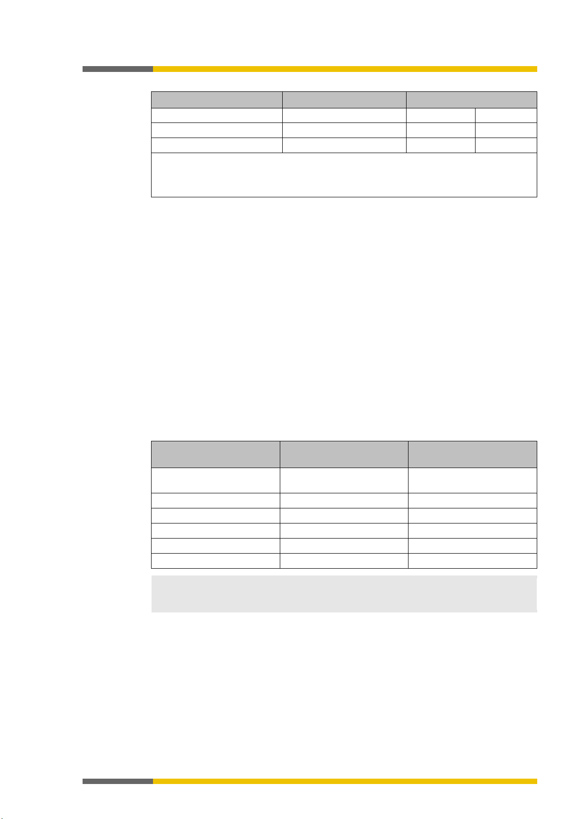
Document
Title
Item number
Software manual
samosPLAN5+ software
BA000968
Hardware manual
samosPRO hardware
BA000966
Gateway manual
samosPRO gateways
BA000970
samosPRO)
fety control)
control)
(samosPRO-PROFIBUS-DP gateway)
(samosPRO-CANopen gateway)
(samosPRO EtherCAT gateway)
planners, developers
operators
1.2
1.3
Scope of validity and applicable documents
910727051
This manual applies to the following gateway modules:
• SP-EN-MOD
• SP-EN-PN
• SP-EN-IP
• SP-PROFIBUS-DP
• SP-CANopen
• SP-EN-ETC
Table 1: Overview of the samosPRO documentation
Operating instructions
Operating instructions
Operating instructions
Operating instruc-
SP-COPx
(Controller modules of the modular safety control
SP-SDI/SP-SDIO
(Expansion modules of the modular samosPRO sa-
SP-DIO
(Expansion module of the modular samosPRO safety
SP-PROFIBUS-DP
BA000978
BA000515
BA001033
BA000572
tions
Operating instruc-
SP-CANopen
BA000683
tions
Operating instruc-
SP-EN-ETC
BA000959
tions
Target audience
910723979
This manual is aimed at the
modular samosPRO safety controls and that want to exchange data with a field bus (controls)
via a gateway.
It is also aimed at persons commissioning a samosPRO gateway system for the first time or
maintaining such a system.
and
of systems that incorporate
Page 10

About this manual
Wieland Electric GmbH | BA000970 | 11/2016 (Rev. F)
10
ATTENTION
Observing safety information and protective measures
1.4
Information depth
910725515
This manual contains information about the following topics related to samosPRO gateways:
• Installation
• Integration into the network
• Configuration with the samosPLAN5+ software
• Data transmission to and from the network
• State information, projection and associated mapping
• Item numbers
Observe the safety information and protective measures for the samosPRO gateways described in this manual.
Downloads are provided at the following link http://www.wielandinc.com/
Also consult our website on the Internet. At the following link http://www.wielandinc.com/,
you will find:
• the samosPLAN5+ software
• The samosPRO manuals available for display and printing in various languages:
– This gateway manual (BA000970)
– The hardware manual (BA000966)
– The software manual (BA000968)
• The GSD file of the SP-PROFIBUS-DP for PROFIBUS-DP
Important information
• The EDS file of the SP-CANopen for CANopen
Page 11

About this manual
Wieland Electric GmbH | BA000970 | 11/2016 (Rev. F)
11
Term
Explanation
0b
The following are specified in binary format
ACD
Address Collision Detection
ANSI
American National Standards Institute, specified character coding
AOI
Add On Instruction
AOP
Add On Profile
API
Actual Packet Interval
NET IO between the PLC and the device
Attribute
Characteristic or property of an object
Bit
Data unit with a value of 0 or 1
which each of the 8 bits is viewed individually
CIP
Common Industrial Protocol
Cyclic Redundancy Check, a type or the result of a hash function for
revealing errors in the area of data storage or transmission
12 bytes of the relevant data set (depending
on the gateway used).
state data. A data set can consist of several data blocks.
I/O
Input/output
EPATH
Encoded Path, especially for CIP applications
technologies with CIP
Net/IP, PROFIBUS DB, CANopen, Modbus TCP, etc.
ID
An identifier or an identity
specification, version 3.18)
attribute values. (Reference: CIP specification, version 3.18)
ment
1.5
Abbreviations and Definitions
1127430283
{ } An element array or an element structure
0x The following are specified in hexadecimal format
Procedure error A procedure error occurs if, in redundant input circuits, the two
input signals are not equal. Monitoring of inequality is frequently
carried out within a tolerated time window.
AR Application Relation, unique communication relationship in PROFI-
BOOL Data type specified for CIP devices; stands for a value of 1 byte, in
Byte, BYTE Data unit, representing a sequence of 8 bits; without a plus/minus
sign, if not specified
Controller module Controller from the samosPRO COMPACT product family
CRC
Data block A data block contains 2-
Data set Describes a quantity of associated data, e.g. logic values or system
EtherNet/IP Industrially-used Ethernet network, combines standard Ethernet
Gateway Connection module for industrially-used networks, such as Ether-
Instance The physical representation of an object within a class. It stands for
one of several objects within the same object class. (Reference: CIP
IP Internet protocol
Class A series of objects representing a similar system component. A
class is a generalization of the object, a template for defining variables and methods. All the objects within a class are identical with
regard to function and behavior. However, they may have differing
LSB Low Significant Byte
MPI Measured Packet Interval; shows the API at the time of measure-
Page 12

About this manual
Wieland Electric GmbH | BA000970 | 11/2016 (Rev. F)
12
Term
Explanation
MSB
Most Significant Byte
O→T
Originator to Target (sender to target device)
ODVA
Open Device Vendor Association
PC
Personal Computer
PLC
Programmable Logic Controller
RX
Receive
modules.
Examples: GetAttributeSingle, SetAttributeSingle
byte per character, 1 byte length code)
sion gateways and I/O modules.
puts and gateway functions, amongst other things
( PLC)
input circuits or using test pulses in input and output circuits.
immediate error recognition.
T→O
Target to Originator
transport layer specified in RFC 793
offs / interruptions in input
nuous basis.
ve test result and thus switch-off of the affected safety circuits.
TX
Transmit / Send
UCMM
Unconnected Message Manager
Data type specified for CIP applications
col, Internet standard protocol for the transport
layer specified in RFC 793
PCCC Programmable Controller Communication Command
RPI Requested Packet Interval
S/N Serial number
samosPLAN5+ Configuration software for controller modules of type SP-COP. The
software can be run on a PC and communicates with the controller
Service Service to be performed
SHORT_STRING Data type specified for CIP devices; stands for a character string (1
SINT Short integer = 1 byte
SP-COP Safety controller consisting of a controller module of the samosPRO
COMPACT product family, as well as optionally connectable expan-
SP-COP2-ENI Controller module, which is equipped with safety inputs and out-
PLC Programmable Logic Controller
Stuck-at high Stuck-at high is an error in which the input or output signal gets
stuck at On. The causes for a Stuck-at high can be short-circuits to
other input and output lines, often called cross-references, or defective switching elements. Stuck-at high errors are discovered
through plausibility tests, such as sequence errors in two-channel
Stuck-at low Stuck-at low is an error in which the input or output signal gets
stuck at Off. The causes of a stuck-at low can be line interruptions
in input circuits or defect switching elements. Stuck-at low errors
are discovered through plausibility tests and usually do not require
TCP Transmission Control Protocol, Internet standard protocol for the
Test pulses or scan
gaps
Test pulse error Test pulse errors are undetected test pulses, which lead to a negati-
Test pulses or scan gaps are brief switchand output circuits, which are generated in a targeted manner to
detect stuck-at high errors quickly. Test pulses check the switch-off
ability of switching elements during operation on an almost conti-
UDINT Unsigned double integer = 4 Bytes = 2 Words
UDP User Datagram Proto
Page 13

About this manual
Wieland Electric GmbH | BA000970 | 11/2016 (Rev. F)
13
Term
Explanation
UDT
User Defined Type
Data type specified for CIP applications
without a plus/minus symbol
UINT Unsigned double integer = 2 Bytes = 1 Word
USINT Data type specified for CIP applications, which stands for 1 byte
Page 14

Wieland Electric GmbH | BA000970 | 11/2016 (Rev. F)
14
NOTICE
These are notes that provide you with information regarding particularities of a device or a
software function.
Warning!
Please read and follow the warnings carefully!
to occur.
bold font
Edit
File
1.6
ATTENTION
About this manual
Symbols/icons and writing style/spelling standard used
840010507
A warning lets you know about specific or potential hazards. It is intended to protect you
from accidents and help prevent damage to devices and systems.
•
Failure to do so may negatively impact the safety functions and cause a hazardous state
Menus and commands
The names of software menus, submenus, options, and commands, selection fields, and
windows are written in
. Example: Click on
in the
menu.
Page 15

Safety
Wieland Electric GmbH | BA000970 | 11/2016 (Rev. F)
15
and
and
ATTENTION
Do not operate a samosPRO gateway on a safety field bus!
related field bus data (state bytes) for control and diagnostic
cation within a safety network.
Do not use data from a samosPRO gateway for safety-related applications!
checked by a safety specialist.
ATTENTION
The safety instructions and precautions for use of samosPRO gateways must be adhered
to!
NOTICE
• Please follow the standards and guidelines valid in your country when installing and ope-
2
2.1
2.2
Safety
910731659
This section is intended to support your safety and the safety of the system users.
Please read this section carefully before you work with a samosPRO system.
Qualified persons
911377675
A safety controller with samosPRO gateways may only be installed, commissioned, and maintained by qualified persons.
Qualified persons are those who
• have suitable technical training
• have been trained by the machine operator in the operation and applicable safety guidelines
• have access to the samosPRO system operating instructions and have read them and duly
noted their contents.
Proper use
911379211
The samosPRO gateways can only be operated in conjunction with a samosPRO safety controller. The firmware version of the connected controller modules must be at least V1.0.0 and the
version of the samosPLAN5+ configuration software must be at least 1.0.0.
The samosPRO gateways do not have their own power supply.
The gateway modules are not suitable for operation with a safety field bus!
They do not only generate safetypurposes. They do not support any safety mechanisms that would be required for communi-
The samosPRO gateways can be used to integrate non-safety-related data into the logic editor in such a way that the safety function of the samosPRO system may be adversely affected.
ATTENTION
• Never integrate a gateway into a samosPRO system without having this source or risk
These modules may only be operated by qualified staff and may only be used on a machine on
which they have been installed and commissioned for the first time by a qualified person in accordance with this manual.
In the event of any other use or any changes to the device – including within the scope of
installation – this shall nullify any warranty claim with respect to Wieland Electric GmbH.
rating the samosPRO gateways.
• The national/international legal regulations apply to the installation and use of the modular samosPRO safety controls as well as for the commissioning and repeated technical
testing, particularly the following:
– EMC Directive 2004/108/EC,
– the Use of Work Equipment Directive 2009/104/EC,
– the accident prevention / safety regulations.
• The manual must be provided to the operator of the machine on which the samosPROsystem is to be used. The machine operator must be trained by qualified persons and is
required to read this manual.
Page 16

Safety
Wieland Electric GmbH | BA000970 | 11/2016 (Rev. F)
16
ATTENTION
May only be used in an industrial environment
NOTICE
We will be happy to help you in disposing of these devices.
Simply contact us.
ATTENTION
Important information
Components
Disposal
electric connecting pieces
Cardboard, paper
Paper/cardboard recycling
2.3
2.3.1
2.3.2
The samosPRO system fulfills the requirements for class A (industrial applications) according
to the "Emitted interference" basic technical standard. The samosPRO system is therefore
only suitable for use in an industrial environment.
Environmentally friendly behavior
888332555
The modular samosPRO safety control and the corresponding modules are designed such that
they stress the environment as little as possible. They use only a minimum of power and resources.
Make sure that you also carry out work while always considering the environment.
Disposal
888334091
The disposal of unusable or irreparable devices should always be done in accordance with the
respectively valid country-specific waste-elimination guidelines (e.g. European Waste Code 16
02 14).
Sorting of materials
888335627
• The sorting of materials may only be carried out by qualified persons!
• Care must be used when disassembling the devices. There is a risk of injuries during this
process.
Before you can route the devices to the environmentally-friendly recycling process, it is necessary to sort the various materials of the samosPRO devices.
Separate the housing from the rest of the components (particularly from the PC board).
Place the separated components into the corresponding recycling containers (see the
following table).
Table 2: Overview of disposal according to components
Product
Housing
PC boards, cables, connectors, and
Packaging
Plastic recycling
Electronics recycling
Page 17

Product description
Wieland Electric GmbH | BA000970 | 11/2016 (Rev. F)
17
ATTENTION
Do not operate a samosPRO gateway on a safety field bus!
related field bus data (state bytes) for control and diagnostic
cation within a safety network.
NOTICE
Where not otherwise indicated, this manual always considers the data exchanged between
system and the relevant network from the point of view of the network master
data received from the network is termed output data.
Available with controller module version and higher
Feature/
functionality
SP-COP1-x
SP-COP2-EN-x
SP-COP2-ENI-x
samosPLAN5+
Modbus TCP
---
---
A-01
V1.0
PROFINET IO
---
---
B-01.xx
V1.2
EtherCAT (SP-EN-ETC)
C-01.xx
C-01.xx
C-01.xx
V1.3
EtherNet/IP
---
---
D-01.xx
V1.4
PROFIBUS DP
A-01
A-01
A-01
V1.0
CANopen
A-01
A-01
A-01
V1.0
3
3.1
Product description
910740875
samosPRO gateways allow a samosPRO system to transmit non-safety-related data for control
and diagnostic purposes to the external field bus system and to receive them.
The gateway modules are not suitable for operation with a safety field bus!
They do not only generate safety-
Important safety information
purposes. They do not support any safety mechanisms that would be required for communi-
Information on the function, configuration and designations
the samosPRO
(PLC). Thus data sent to the network from the samosPRO system is termed input data, while
Configuration of samosPRO gateways takes place via the samosPLAN5+ configuration software, using a PC or Notebook connected to the SP-COPx main module via the USB interface
or RJ45 Ethernet interface.
The safety-related logic of the samosPRO system works independently of the gateway. However, if the system has been configured in such a way that non-safety-related information from
the field bus can be integrated into the logic editor, switching off the gateway may result in
availability problems.
A samosPRO gateway can only be operated on a samosPRO system. It does not have its own
power supply. A maximum of two samosPRO gateways can be operated simultaneously for
each system.
The gateway for Modbus TCP, PROFINET IO or EtherNet/IP is integrated into the SP-COP2-ENI
controller module, while the gateways for Profibus-DP, CANopen or EtherCAT are housed in a
22.5 mm wide installation housing for 35 mm standard rails in accordance with EN 60715.
Order information:
Order data [ch. 13, p. 198]
Version, compatibility, and features
1184672907
There are various module versions and function packages for the samosPRO product family
that enable various functions. This section will give you an overview as to which module version, which function package, and/or which version of the samosPLAN5+ software you will
need to be able to use a certain function or a certain device.
Table 3: Required versions of the controller module
Page 18
Product description
Wieland Electric GmbH | BA000970 | 11/2016 (Rev. F)
18
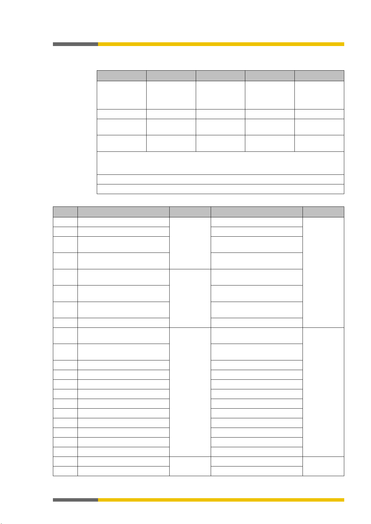
Gateway
Module name
Versions
EtherCAT
SP-EN-ETC
A-011)
A-021)
PROFIBUS DP
SP-PROFIBUS-DP
A-02
A-03
CANopen
SP-CANopen
A-01
A-02
CANopen emergency messages are fully functional.
S/N
Gateway
Network type
Ethernet TCP/IP socket interface
slave operation
SP-EN-PN
PROFINET IO device
-
SP-EN-IP
EtherNet/IP device
-
SP-PROFIBUS-DP
PROFIBUS DP slave
–
SP-EN-ETC
EtherCAT slave
-
NOTICE
You will find the manufacturing date of a device on the type label in the S/N field in the for-
calendar week).
3.2
Table 4: Versions of the gateway modules
1)
The EtherCAT node ID cannot be saved in the gateway.
2)
The manufacturer-specific expanded diagnostics are fully functional.
3)
2)
3)
Info
• You can find the module version on the type plate of the modules.
• You will find the samosPLAN5+ software version in the main menu.
• The latest software version is available in the Internet at the following address
http://www.wielandinc.com/.
• Newer modules are backwards-compatible, which means that each module can be replaced with a module having a higher module version.
• You can find the date of manufacture for a device on the type plate in the
format <Product no.>yywwnnnnn (yy = year, ww = calendar week).
field in the
Equipment variants
910741899
There are three samosPRO gateways for various network types.
The Modbus TCP / PROFINET IO and EtherNet/IP gateway of the SP-COP2-ENI controller module or the external SP-EN-ETC gateway are suitable for Ethernet networks. The SPPROFIBUS-DP gateway and the SP-CANopen gateway are external field bus gateways without
an Ethernet function.
Table 5: Equipment variants and their main characteristics
SP-EN-MOD Modbus TCP with master and
Client/Server on Port 502
SP-CANopen CANopen slave –
mat yywwnnnn (yy = year, ww = calendar week, nnnn = consecutive serial number within a
Page 19

Product description
Wieland Electric GmbH | BA000970 | 11/2016 (Rev. F)
19
Logic results from
Input values
Output values
Output data
Test values
Error and state information
Data set 1
Data set 2
Data set 3
Data set 4
3.3
Data transferred to the network (network input data sets)
910743435
Available data
The samosPRO gateways can provide the following data:
• Operating data
–
37]
)
–
–
Module state / input and output values [ch. 3.3.1, p. 22]
–
samosPRO system (see
• Diagnostics
–
–
23]
Data sets
The physical modules are not presented as typical hardware modules in the network. Instead,
the data provided by the samosPRO system has been arranged in four
•
samosPLAN5+. In the form in which it is delivered, the content of data set 1 is preconfigured; it can be freely modified.
Details: see table
For the SP-PROFIBUS-DP gateway, data set 1 was divided into five input data blocks, with
data blocks 1–4 each containing 12 bytes and data block 5 two bytes.
For the SP-CANopen gateway, data set 1 was divided into four blocks, each with 8 bytes.
You will find more detailed information in the corresponding section for each gateway.
•
See table "Overview of input data sets 1-3 (basic settings for Modbus TCP)" below
•
four (4) bytes per module, with the controller module comprising 3 x 4 bytes. Details: see
table
"Meaning of module state bits" [ch. 3.3.5, p. 23]
•
(CRCs): (see
(max. 50 bytes) contains the operating data. It can be compiled with the aid of
(32 bytes) contains the test values (CRCs) for the system configuration.
(60 bytes) contains the state and diagnostic data for the various modules, with
(60 bytes) is currently filled with reserved values.
the samosPRO safety controller (see
(HIGH/LOW) for all samosPRO input expansion modules in the system
(HIGH/LOW) for all samosPRO input/output expansion modules (see
from another network, i.e. data received from a second gateway in the
Routing table [ch. 5.1.2, p.
)
Transmission of data from a second network [ch. 3.3.3, p. 23]
Configuration test values (CRCs) [ch. 3.3.4, p. 23]
:
Error and state information for the modules [ch. 3.3.5, p.
"Overview of input data sets" [ch. 3.3, p. 20]
input data sets
)
.
)
Page 20
Product description
Wieland Electric GmbH | BA000970 | 11/2016 (Rev. F)
20
Data set 1
Data set 2
Data set 3
Data set 4
EtherNet/IP
EtherNet/IP
EtherNet/IP
DP
(SDOs)1)
(SDOs)1)
CANopen gateway may be found here:
CANopen gateway [ch. 10, p. 129]
Readable with instance 2 of class 120
Readable with instance 3 of class 120 and byte 52 to 111 of assembly 167
Data set 1
Data set 2
Data set 3
Data set 4
Byte 0
Input values for Module 0 (I1..I8)
Module state SP-COPx
(IQ1..IQ4)
module inputs
(Q1..Q4, IQ1..IQ4)
module inputs
module inputs
module inputs
module inputs
Byte 7
Direct data (Off) 3
Reserved
le outputs
Byte 10
Direct data (Off) 6
Reserved
Byte 12
Input values for Module 1
State of Module 1
Byte 14
Input values for Module 3
State of Module 1
Byte 15
Input values for Module 4
State of Module 1
Byte 16
Input values for Module 5
State of Module 2
Byte 17
Input values for Module 6
State of Module 2
Byte 18
Input values for Module 7
State of Module 2
Byte 19
Input values for Module 8
State of Module 2
Byte 20
Input values for Module 9
State of Module 3
Byte 21
Input values for Module 10
State of Module 3
The following table provides an overview of which data sets are provided by which gateway.
Table 6: Availability of data sets 1–4
SP-COP2-ENI Modbus TCP
PROFINET IO
SP-EN-ETC EtherCAT EtherCAT EtherCAT -
SP-PROFIBUS-
PROFIBUS DP – – –
SP-CANopen CANopen CANopen
1)
The SP-CANopen is used to provide diagnostic data via CANopen SDO (service data ob-
jects). More information about how to provide state and diagnostic data with the aid of the
2)
3)
Table 7: Overview of input data sets 1–3 (basic setting for Modbus TCP)
Byte 1 Input values for Module 0 (I9..I16)
Byte 2 Input values for Module 0
Byte 3 Output values for Module 0
Modbus TCP
PROFINET IO
Project CRC
Modbus TCP
PROFINET IO
CANopen
Module state SP-COPx
Test pulse comparison, controller
Test pulse comparison, controller
Modbus TCP
PROFINET IO
–
Reserved
Byte 4 Direct data (Off) 0 System CRC
Test pulse comparison, controller
(PROFIBUS
Byte 5 Direct data (Off) 1 State of two-channel controller
DP and
EtherCAT)
Byte 6 Direct data (Off) 2 State of two-channel controller
Byte 8 Direct data (Off) 4 Reserved Stuck-at error at controller modu-
Byte 9 Direct data (Off) 5 Stuck-at error at controller modu-
le outputs
Byte 11 Direct data (Off) 7 Reserved
Byte 13 Input values for Module 2 State of Module 1
Reserved
Reserved
Reserved
Page 21
Wieland Electric GmbH | BA000970 | 11/2016 (Rev. F)
21
Data set 1
Data set 2
Data set 3
Data set 4
Byte 22
Input values for Module 11
State of Module 3
Byte 23
Input values for Module 12
State of Module 3
Byte 24
Output values for Module 1
State of Module 4
Byte 25
Output values for Module 2
State of Module 4
Byte 26
Output values for Module 3
State of Module 4
Byte 27
Output values for Module 4
State of Module 4
Byte 28
Output values for Module 5
State of Module 5
Byte 29
Output values for Module 6
State of Module 5
Byte 30
Output values for Module 7
State of Module 5
Byte 31 Output values for Module 8 State of Module 5
Byte 32
Output values for Module 9
State of Module 6
Byte 34
Output values for Module 11
State of Module 6
Status of Module 9
Byte 48
State of Module 10
Byte 49
State of Module 10
Byte 50
State of Module 10
Byte 51
State of Module 10
Status of Module 11
Byte 56
State of Module 12
Byte 57
State of Module 12
Byte 58
State of Module 12
Byte 59
State of Module 12
Length
50 bytes
32 bytes
60 bytes
60 bytes
NOTICE
When two-channel input or output elements have been configured for an I/O module, only
put or output state (on/off) for the corresponding element. It is
put/output.
NOTICE
The input values in data set 1 do not represent the physical state at the input terminals, but
the pre-processed input values that are used for logic processing.
Not available
Byte 33 Output values for Module 10 State of Module 6
Byte 35 Output values for Module 12 State of Module 6
Byte 36
…
Not allocated State of Module 7
…
Byte 47
Product description
Reserved
Byte 52
…
Byte 55
Not available
State of Module 11
…
the lowest bit constitutes the in
represented by the tag name of the element. The highest bit represents the state of this in-
Page 22

Product description
Wieland Electric GmbH | BA000970 | 11/2016 (Rev. F)
22
Module state
Size
Meaning
Assignment
Input data state
0 = error 1 = no error
reserved
Output data state
NOTICE
The input and output states of the SP-SDI and SP-SDIO modules is only available from firmware version V2.00.0.
Input values for I/O modules
Output values for I/O modules
3.3.1
3.3.2
Direct gateway output values
910745483
It is possible to write values directly from the logic editor to a gateway. Four bytes have been
reserved for this purpose in the basic settings for data set 1; however, up to the total number
of 50 bytes of data set 1 may be configured as direct gateway output values. You can obtain
additional information at:
Module state / input and output values
910746507
Direct gateway output values [ch. 5.3, p. 44]
The samosPRO gateways can transmit the input and output states of all modules connected to
the samosPRO system to the network. Data set 3 contains a non-modifiable configuration. Moreover, data set 1 can be adapted to contain up to 4 bytes of collective state information. Only
the input and output values for data set 1 have been predefined and these can be freely adapted. You will find more detailed information in the section on the relevant gateway, as well as
in the following section:
Configuration of gateways [ch. 5, p. 35]
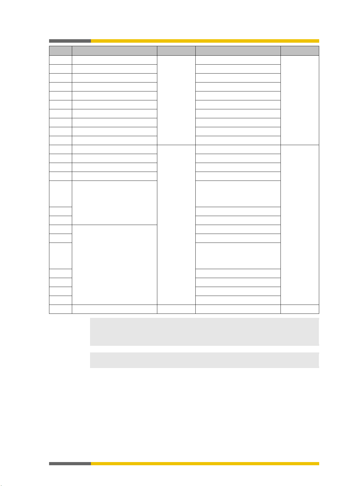
Module state
The samosPRO gateways can transfer the state of the linked modules to the network. A total
of 4 bytes are available for this purpose.
Table 8: Module state
.
2 bytes One sum bit per module for the state
of the module inputs
Bit 0 = SP-COPx
Bit 1 = 1.
Extension module
2 bytes One sum bit per module for the state
of the module outputs
0 = error 1 = no error
Bit 2 = 2.
Expansion module …
Bit 13 = 1.
Gateway Bit 14 = 2.
Gateway Bit 15 =
You will find information about the meaning of the state bits at: software manual, Status bits
for controller modules (reference)
Input and output values for the modules
•
1 byte for data set 1 is available for every expansion module. The input values show the
state of the preliminary evaluation of the I/O module. This corresponds to the state of the
element in the controller module logic. The level at the associated terminal cannot be
clearly detected from this, as the data may be set to low, irrespectively of the level at the
input terminal, by means of the cross-connection detection or two-channel evaluation (e.g.
I1-18).
When two-channel input elements have been configured for an I/O module, only the lower-value bit represents the pre-evaluation state of the corresponding element (e.g. bit 0
for I1 and I2, bit 2 for I3 and I4, bit 4 for I5 and I6, bit 6 for I7 and I8). The higher-value bit
(bit 1, 3, 5 and 7) is used as follows in this case:
0 = error 1 = no error
•
1 byte for data set 1 is available for every module with outputs. The output values indicate
the state of the control information from the logic of the controller module for the relevant
element of the I/O module. The level of the associated terminals cannot be clearly detected
from this, as the output may be switched off via the cross-connection detection or the
overload connection function.
When two-channel output elements have been configured for an I/O module, only the lo-
Page 23

Product description
Wieland Electric GmbH | BA000970 | 11/2016 (Rev. F)
23
NOTICE
You can find an explanation of the technical terms used below here:
Abbreviations and Defi-
nitions [ch. 1.5, p. 11]
Bit 7
Bit 6
Bit 5
Bit 4
Bit 3
Bit 2
Bit 1
Bit 0
Byte 0
shut-off
state
state
Byte 1
current
current
current
current
3.3.3
3.3.4
3.3.5
wer-value bit represents the control information (e.g. bit 0 for Q1 and Q2, bit 2 for Q3 and
Q4, bit 4 for Q5 and Q6, bit 6 for Q7 and Q8). The higher-value bit (bit 1, 3, 5 and 7) is not
used as follows in this case (low):
Transmission of data from a second network
910747531
If your samosPRO system contains two gateways, it is possible to forward information which
the first gateway receives from a network (e.g. from a Modbus PLC) via the second gateway to
a second network (e.g. to a PROFIBUS master) and vice versa.
Configuration test values (CRCs)
910749067
Data set 2 contains the following configuration check values of the samosPRO system:
• Project CRC of the project file created with samosPLAN5+
• System-CRC, uniquely assigned to a module version, consisting of internal software and
hardware version
The CRCs are each 4 bytes in length. Data set 2 can be read only.
The project CRC with Modbus/TCP is transmitted in Big Endian format.
The system CRC is available from module version B-01.01 for PROFIBUS DP and EtherCAT.
Error and state information for the modules
910750603
Data set 3 and 4 contain the state information for the modules that will be transferred to the
network.
Ten bytes are transmitted for SP-COPx controller module. For each SP-SDI and SP-SDIO I/O
module, four bytes are transmitted in the Little Endian format, e.g. as a 32-bit word, with the
first byte being placed into the least significant byte of the whole number (extreme left) and
the fourth byte into the most significant byte of the whole number (extreme right).
Data sets 3 and 4 cannot be adapted.
Module state bits of the controller module SP-COPx
The module state bits have the following meaning, if not otherwise indicated:
0 = error
1 = no error
Reserved bits have the value 1
B2 state Collective
Module
Table 9: Meaning of module state bits of controller module SP-COPx (only for Modbus)
state output data
error fast
Module
state of
input data
B1 state Configura
tion state
Reserved Reserved IQ3+IQ4
A1 state External
module
IQ1+IQ2
power
requirement
0: Excess
current
1: no
excess
power
require-
ment
0: Excess
current
1: no
excess
Internal
module
Q3+Q4
power
requirement
0: Excess
current
1: no
excess
Reserved
Q1+Q2
power
requirement
0: Excess
current
1: no
excess
Page 24

Product description
Wieland Electric GmbH | BA000970 | 11/2016 (Rev. F)
24
Bit 7
Bit 6
Bit 5
Bit 4
Bit 3
Bit 2
Bit 1
Bit 0
Byte 2
son
son
son
son
son
son
son
son
Byte 3
son
son
son
son
son
son
son
Byte 4
son
son
son
son
Byte 5
not used
not used
not used
not used
not used
not used
not used
not used
Byte 6
not used
not used
Byte 7
Reserved
Reserved
Reserved
Reserved
Reserved
Reserved
Reserved
Reserved
Byte 8
low
high
low
high
low
high
low
high
Byte 9
low
high
low
high
low
high
low
high
NOTICE
The module state bits for the SP-SDI and SP-SDIO modules are only fully supported from
firmware version 1.2.x.
I8 vs. T2/4
test pulse
compari-
I16 vs.
T2/4 test
pulse
compari-
Reserved Reserved Reserved Reserved IQ4 vs.
I15/I16
twochannel
state
0: Error
1: ok or
I7 vs. T1/3
test pulse
compari-
I15 vs.
T1/3 test
pulse
compari-
I13/I14
twochannel
state
0: Error
1: ok or
I6 vs. T2/4
test pulse
compari-
I14 vs.
T2/4 test
pulse
compari-
I11/I12
twochannel
state
0: Error
1: ok or
I5 vs. T1/3
test pulse
compari-
I13 vs.
T1/3 test
pulse
compari-
I9/I10
twochannel
state
0: Error
1: ok or
I4 vs. T2/4
test pulse
compari-
I12 vs.
T2/4 test
pulse
compari-
T2/4 test
pulse
compari-
I7/I8
twochannel
state
0: Error
1: ok or
I3 vs. T1/3
test pulse
compari-
I11 vs.
T1/3 test
pulse
compari-
IQ3 vs.
T1/3 test
pulse
compari-
I5/I6
two-
channel
state
0: Error
1: ok or
I2 vs. T2/4
test pulse
compari-
I10 vs.
T2/4 test
pulse
compari-
IQ2 vs.
T2/4 test
pulse
compari-
I3/I4
twochannel
state
0: Error
1: ok or
Reserved Reserved Reserved Reserved Reserved Reserved IQ3/IQ4
twochannel
state
0: Error
1: ok or
I1 vs. T1/3
test pulse
compari-
I9 vs. T1/3
test pulse
comparison
IQ1 vs.
T1/3 test
pulse
compari-
I1/I2
twochannel
state
0: Error
1: ok or
IQ1/IQ2
twochannel
state
0: Error
1: ok or
Q4
Stuck at
IQ4 (Out-
put)
Stuck at
Q4
Stuck at
IQ4 (Output)
Stuck at
Q3
Stuck at
IQ3 (Output)
Stuck at
Q3
Stuck at
IQ3 (Output)
Stuck at
Q2
Stuck at
IQ2 (Output)
Stuck at
Q2
Stuck at
IQ2 (Out-
put)
Stuck at
Q1
Stuck at
IQ1 (Output)
Stuck at
Q1
Stuck at
IQ1 (Output)
Stuck at
Module state bits of the I/O modules SP-SDI and SP-SDIO
The module state bits have the following meaning, if not otherwise indicated:
0 = error
1 = no error
Page 25

Product description
Wieland Electric GmbH | BA000970 | 11/2016 (Rev. F)
25
Bit 7
Bit 6
Bit 5
Bit 4
Bit 3
Bit 2
Bit 1
Bit 0
Byte 0
valid.
Byte 1
I7–I8
I5–I6
I3–I4
I1–I2
Byte 2
X2
X1
X2
X1
X2
X1
X2
X1
Byte 3
stuck-at
stuck-at
stuck-at
stuck-at
stuck-at
stuck-at
stuck-at
stuck-at
Bit 7
Bit 6
Bit 5
Bit 4
Bit 3
Bit 2
Bit 1
Bit 0
Byte 0
IY5-IY8
Byte 1
put data
data
Byte 2
Reserved
Byte 3
Reserved
Reserved Collective
Module
Test im-
Q4 Stuck-
Table 10: Meaning of the module state bits of the safe I/O modules SP-SDI and SP-SDIO
state of
output
data
pulse
comparison I8 vs.
at low
0: Stuck-at
error
1: no
error fast
shut-off
Module
state of
input data
Test impulse
comparison I7 vs.
Q4 Stuckat high
0: Stuck-at
error
1: no
Power
supply for
Q1 .. Q4
Reserved Reserved Two-
Test impulse
comparison I6 vs.
Q3 Stuckat low
0: Stuck-at
error
1: no
Configuration of this
module is
Test impulse
comparison I5 vs.
Q3 Stuckat high
0: Stuck-at
error
1: no
Not used
(error history flag)
channel
evaluation
of input
Test impulse
comparison I4 vs.
Q2 Stuckat low
0: Stuck-at
error
1: no
External
module
state
Two-
channel
evaluation
of input
Test im-
pulse
compari-
son I3 vs.
Q2 Stuck-
at high
0: Stuck-at
error
1: no
Internal
module
state
Twochannel
evaluation
of input
Test impulse
comparison I2 vs.
Q1 Stuckat low
0: Stuck-at
error
1: no
Not used
("executing state")
Twochannel
evaluation
of input
Test impulse
comparison I1 vs.
Q1 Stuckat high
0: Stuck-at
error
1: no
Module state bits of the SP-DIO I/O module
The module state bits have the following meaning if not otherwise indicated; normally only the
first byte of the total state is transmitted:
0 = error
1 = no error or reserved
Reserved Reserved Power
Module
Table 11: Meaning of the module state bits of the SP-DIO expansion module
state out-
Module
state input
Configura-
supply Y1-
tion state
Y4 and
Reserved Reserved Reserved Reserved Reserved Reserved
Not used
(error history flag)
External
module
state
Internal
module
state
Not used
("executing state")
Page 26
Product description
Wieland Electric GmbH | BA000970 | 11/2016 (Rev. F)
26
Bit 7
Bit 6
Bit 5
Bit 4
Bit 3
Bit 2
Bit 1
Bit 0
Byte 0
data
flag)
Byte 1
Reserved
Byte 2
Reserved
Byte 3
Reserved
Byte address
00
01
02 … 03
11
04
12
05
13
06
14
07
15
08
16
09
17
10
18
11
19
…
Byte
0
… 0 11
Value
EF
FB
FB
EF
Meaning
SDIO)
State of module 2 (
SDIO)
Bit # 7 6 5 4 3 2 1 0
Value 1 1 1 1 1 0 1 1
Bit # 7 6 5 4 3 2 1 0
Value 1 1 1 0 1 1 1 1
NOTICE
• Reserved (for future use) = static 1 (no state change)
• If there is no module, all values - including the reserved values - are set to logical 1.
Module state bit of the gateways
The module state bits have the following meaning if not otherwise indicated; normally only the
first byte of the total state is transmitted:
0 = error
1 = no error
Table 12: Meaning of gateway module state bits
Reserved Module
state
output
Module
state
input data
Configuration state
Not used
(error
history
Reserved Internal
module
state
Not used
("executing state")
Example
Module 2 (SP-SDIO) has a short-circuit after high (24 V) at output 3. The following module state is transmitted to the network (only the first 20 of 60 bytes are shown):
3
FF FF FF FF FF FF FF FF
CPU state State of module 1 (SP-
2 1 1
3 0 2 1 1 2 0 3 3 0 2 1 1 2 0 3 …
FF FF
SP-
…
…
The first relevant byte for the module 2 error described above is module state byte 0 for module 2. This is byte 11 with the hexadecimal value FB (1111 1011):
This corresponds to the error message "Summary of bits 0.5 ibs 0.7 (external error)", byte 0, bit
2 in the following table:
25]
"Meaning of module state bits of the secure I/O modules" [ch. 3.3.5, p.
The second relevant byte is the module state byte 3 for module 2. This is byte 08 with the hexadecimal value EF (1110 1111):
This corresponds to the error message "Short circuit monitoring of output 3, short circuit after
high", byte 3, bit 4 in the following table:
dules" [ch. 3.3.5, p. 25]
"Meaning of module state bits of the secure I/O mo-
• Not used (can be 0 or 1 ), both values occur.
Page 27
Product description
Wieland Electric GmbH | BA000970 | 11/2016 (Rev. F)
27
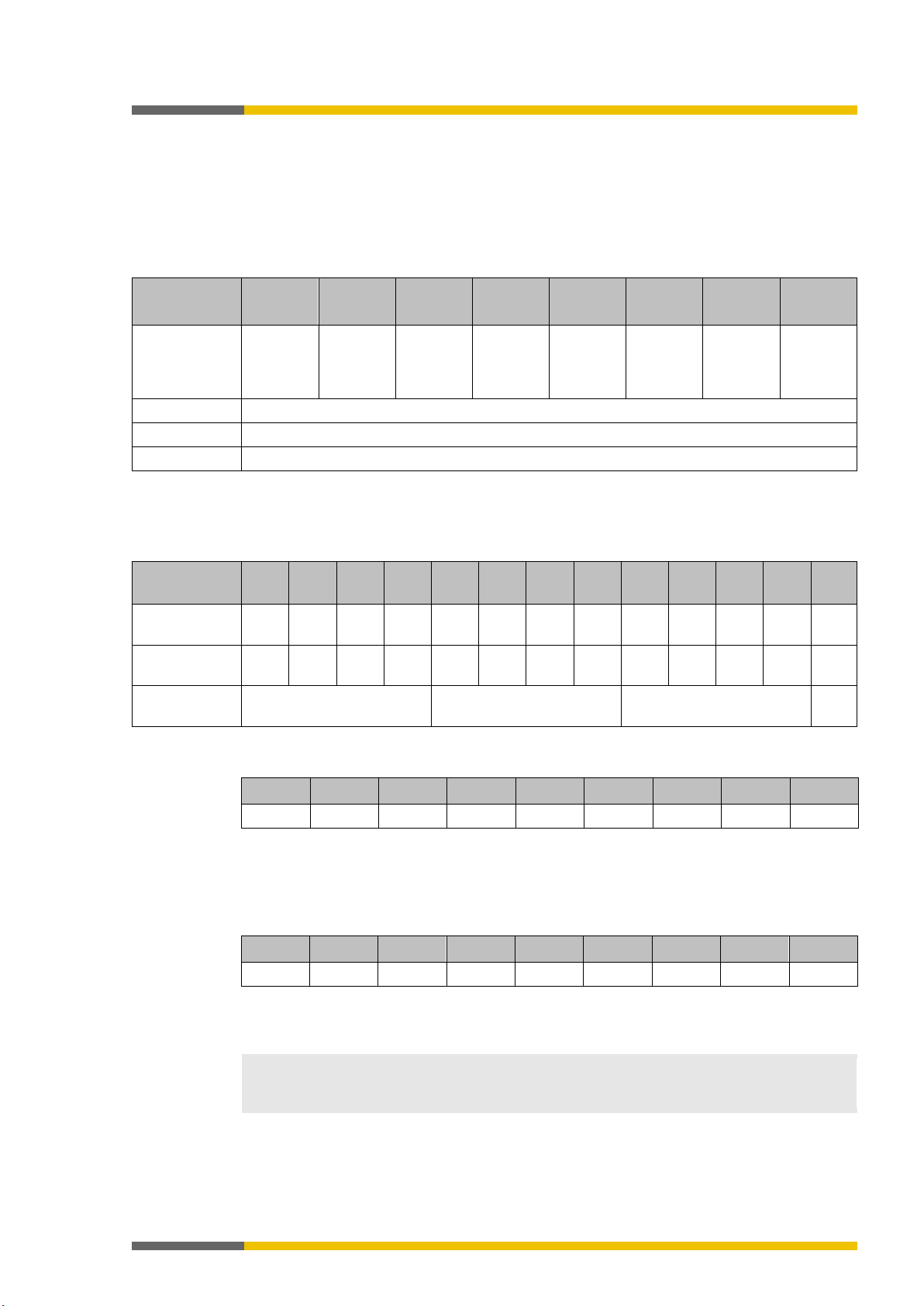
Size of output data block
Gateway
Block 1
Block 2
Block 3
Block 4
Block 5
PROFINET IO
SP-CANopen
8 bytes
8 bytes
8 bytes
8 bytes
–
EtherNet/IP
NOTICE
• In order to use network data in the logic editor or as input for another network, you must
Bits without specific tag names will not be available in the logic editor or for routing via a
You can monitor current communication with the network with the aid of input data state
hen a connection is closed while others remain available, the LED MS or LED state will
flash red/green for a total of 10 seconds and an entry will be made in the error log. In this
case the state bits are not affected.
Do not use the same output data block number for two different PLC connections or
TCP/IP sockets!
te the data received earlier.
3.4
Data received from the network (network output data sets)
910751627
The data from data set 1 (max. 50 bytes) received from the network may be differently arranged, depending on the protocol. For the Modbus TCP, this data set was divided into five data
blocks, each with 10 bytes. In the SP-PROFIBUS-DP gateway, output data blocks 1-4 each
contain 12 bytes, while output data block 5 contains 2 bytes. CANopen only defines 4 data
blocks, each with 8 bytes.
Table 13: Output data block 1–5 of the various gateways
SP-PROFIBUS-DP /
SP-EN-ETC /
12 bytes 12 bytes 12 bytes 12 bytes 2 bytes
10 bytes 10 bytes 10 bytes 10 bytes 10 bytes
Modbus TCP /
The content of the output data blocks can be used in the logic editor, as well as made available
for another network via a second gateway within the samosPRO system.
assign a tag name for each bit to be used.
•
second gateway. Detailed information about how to assign tag names for the data received may be found in the corresponding sections of the chapters on the various gateways.
•
bits for receiving data from the network and the output data state bit for transmitting data to the network in the logic editor. When the gateway detects a communication error,
both the content of the data sets and the associated state bit are set to zero (logical 0).
• When all communication fails, the data of the output data sets and the input data state
bit are set to zero (logical 0).
• W
The output data block of the Ethernet gateways can be described in parallel via all communication interfaces or TCP/IP sockets (e.g. Modbus TCP/IP and Ethernet TCP/IP) if they make
ATTENTION
use of the same output data block number. In this case the last message will always overwri-
Page 28

Installation and basic configuration
Wieland Electric GmbH | BA000970 | 11/2016 (Rev. F)
28
ATTENTION
This is only for switchboxes with protection class IP 54 or higher!
4
4.1
4.1.1
Installation and basic configuration
910753163
Installing/removing
910754699
Installing modules on standard rail
888512651
The samosPRO system is only suitable for installations in a switchbox having at least protection class IP 54.
Info
• Basic safety
Gateways must not be removed or added when the operating voltage is switched on.
• Grounding
The DIN rails must be conductively connected to the protective conductor (PE).
• ESD protection measures
Note the suitable ESD protection measures during installation.
Failure to do so could result in damage to the bus (internal safety bus).
• Protect connector openings
Undertake suitable measures so that no foreign bodies can penetrate connector openings,
particularly those for the program removable storage.
• Module width:
The modules are placed in a mounting box that is 22.5 mm or 45 mm wide depending on
type.
• Quality of standard rail
The mounting boxes are suitable for 35-mm standard rails as per EN 60715.
• Sequence of modules:
The SP-COPx controller module is inserted all the way to the left in a samosPRO system.
The two optional gateways follow directly to the right next to the controller module.
• Save space for subsequent model replacement
The modules are connected via the plug connection integrated into the housing. Note that
the samosPRO modules must be pulled about 10 mm apart for a module replacement before the corresponding module can be removed from the standard rail.
• Standards to be considered
Installation according to EN 50274
Page 29
Installation and basic configuration
Wieland Electric GmbH | BA000970 | 11/2016 (Rev. F)
29
Important!
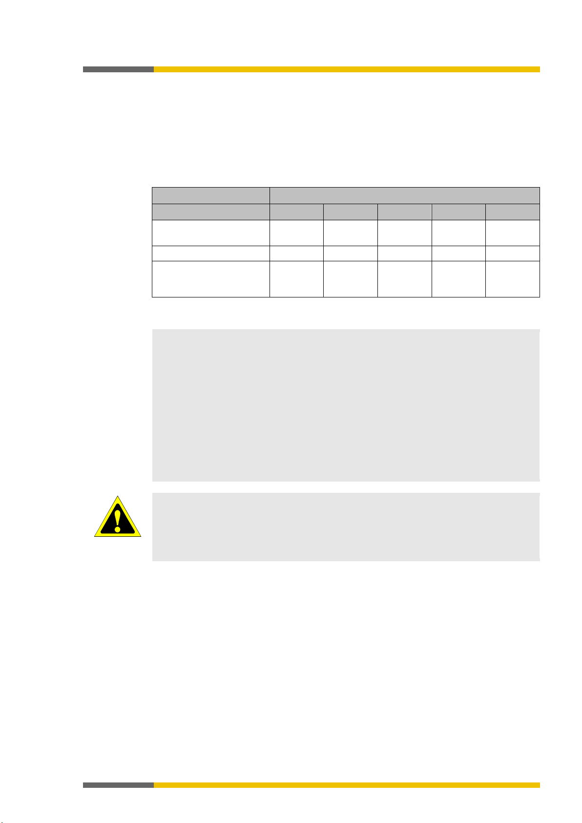
Step 1: Installing a controller module
Using a screwdriver, pull the snap-on foot outward.
Hang the module on the standard rail.
The shielding spring of the module must be placed on the standard rail so that it is secure
and has good electrical conduction.
Make sure that the shielding spring is seated correctly.
Fold the module onto the standard rail.
Using a screwdriver, move the snap-on foot against the standard rail until the snap-on foot
latches into position with an audible click.
Make sure that the module is securely seated on the standard rail.
Attempt to pull the module from the standard rail using slight pressure. If the module stays
connected to the rail during this test, then the installation is correct.
Page 30
Installation and basic configuration
Wieland Electric GmbH | BA000970 | 11/2016 (Rev. F)
30
Important!
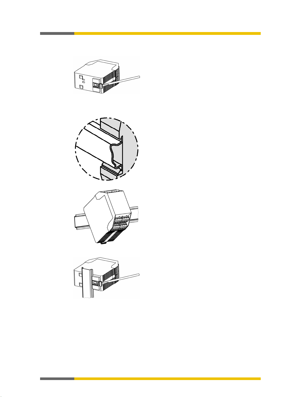
Step 2: Installation of gateways or expansion modules
Hang the module on the standard rail.
The shielding spring of the module must be placed on the standard rail so that it is secure
and has good electrical conduction.
Make sure that the shielding spring is seated correctly.
Using slight pressure, fold the module onto the rail in the direction of the arrow until the
module audibly latches into position.
Make sure that the module is securely seated on the standard rail.
Attempt to pull the module from the standard rail using slight pressure. If the module stays
connected to the rail during this test, then the installation is correct.
If you are installing multiple modules:
Push the modules together individually in the direction of the arrow until the lateral plug
connection between the modules audibly latches into position.
Install an end terminal into the module furthest to the left and another end terminal into
After installation
Once you have installed the modules, the following steps are required:
• Connect the modules electrically.
• Configure modules (see: software manual).
• Check the installation before first commissioning.
the module furthest to the right.
Page 31

Installation and basic configuration
Wieland Electric GmbH | BA000970 | 11/2016 (Rev. F)
31
4.1.2
Removing modules from normal rail
888517003
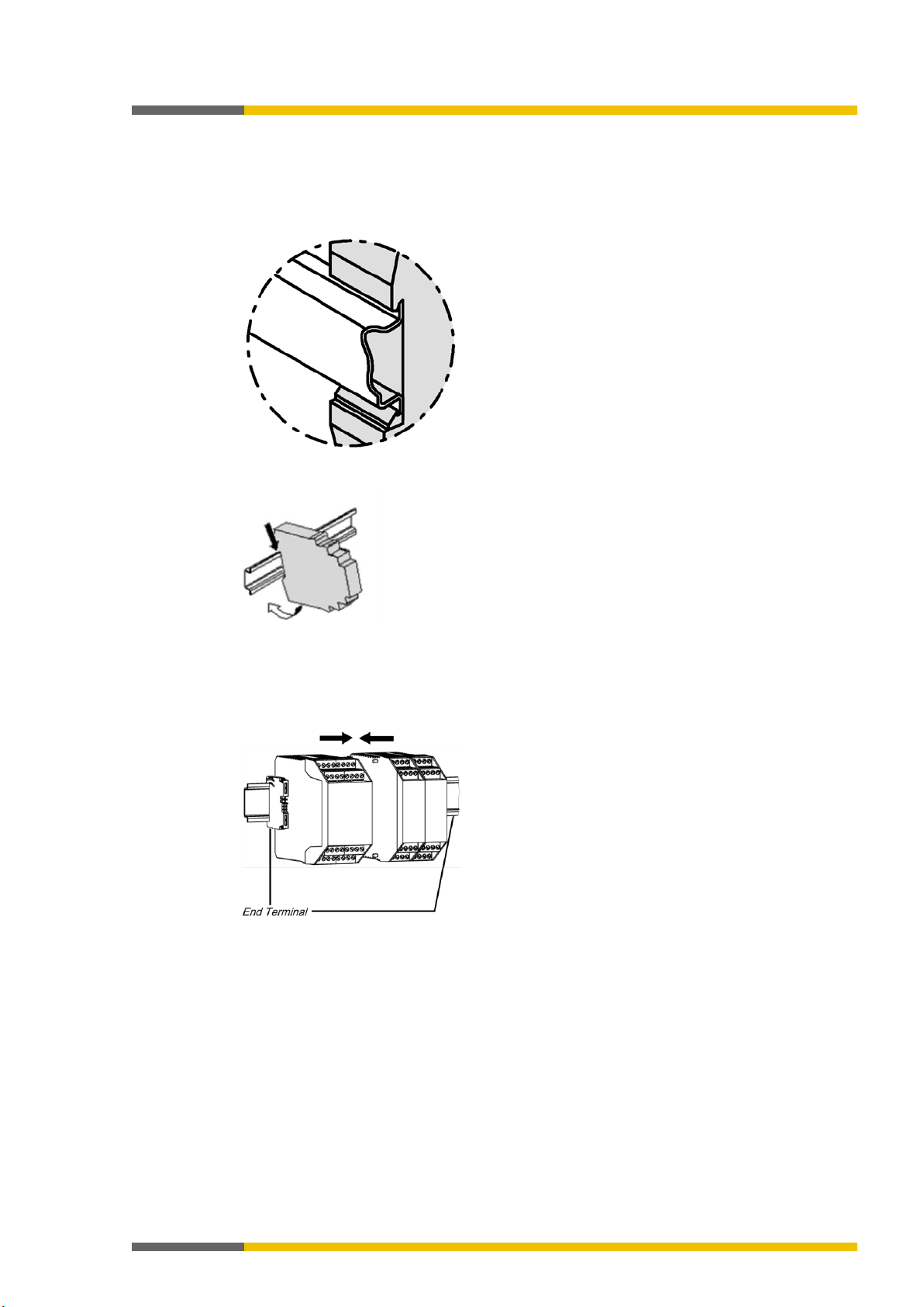
Step 1: Removing a controller module
Deenergize the samosPRO system.
Remove plug-in terminals with wiring and remove the end terminal.
If expansion mode or gateways are used:
Slide the controller module in the direction of the arrow until the lateral plug connection is
disconnected.
Unlock the module.
To do this, pull the snap-on foot of the module outward using a screwdriver.
Page 32

Installation and basic configuration
Wieland Electric GmbH | BA000970 | 11/2016 (Rev. F)
32
Fold the module away from the standard rail and remove it from the rail.
Step 2: Removing gateways and expansion modules
Deenergize the samosPRO system.
Remove plug-in terminals with wiring and remove the end terminals.
Pull the modules apart from one another individually in the direction of the arrow until the
lateral plug connection is disconnected.
Press on the module from above and fold the module away from the standard rail while it
is in the pressed-down state.
Page 33

Installation and basic configuration
Wieland Electric GmbH | BA000970 | 11/2016 (Rev. F)
33
ATTENTION
Switch off the power supply to the system!
NOTICE
• samosPRO gateways meet EMC conditions as set out in the EN 61000-6-2 specification
4.2
Electrical installation
910756235
It is possible for the system to be unexpectedly started while you are connecting the devices.
for use in an industrial environment.
• In order to ensure complete EMC safety, the standard rail must be connected to functional earth (FE).
• The switch box or installation housing for the samosPRO system must meet at least the
requirements of protection class IP 54.
• Installation according to EN 50274.
• Electrical installation as per EN 60204-1.
• The external power supply of the devices must be able to bridge a short-term power outage of 20 ms in accordance with EN 60204-1.
• The power supply must meet the regulations for low-voltage with safe disconnection
(SELV, PELV) in accordance with EN 60664 and EN 50178 (equipping high-voltage systems with electronic equipment).
• Ensure that all modules of the samosPRO system, the connected protective devices and
the power supplies are connected to the same ground connection. The ground of the
RS-232 interface is internally connected to the ground of the power supply for the controller module (A2).
• Connect the shielding of all field bus and Ethernet cables to functional earth (FE) just before they lead into the switch box.
Page 34

Installation and basic configuration
Wieland Electric GmbH | BA000970 | 11/2016 (Rev. F)
34
Step
Description
Establishing a link between the gateway and PC
Software manual, chapter "Connect with the safety control"
Configure gateway
•
EtherCAT Gateway [ch. 11, p. 166]
Transmitting and verifying the configuration
Software manual, chapter "Transferring the system configuration"
4.3
Initial configuration steps
910757771
How do you configure gateways? This chapter provides some brief guidelines.
Table 14: Guidelines for gateway configuration
1
See here for more detailed information:
2
You will find detailed information in this regard at the following points in the
gateway manual:
•
Modbus TCP gateway [ch. 6, p. 49]
PROFINET IO-Gateway [ch. 7, p. 62]
•
EtherNet/IP gateway [ch. 8, p. 76]
•
PROFIBUS DP gateway [ch. 9, p. 114]
•
CANopen gateway [ch. 10, p. 129]
•
3
See here for more detailed information:
Page 35

Configuration of gateways
Wieland Electric GmbH | BA000970 | 11/2016 (Rev. F)
35
Gateways
NOTICE
You will find more detailed information about the graphic user interface in the software manual.
Gateway
Hardware
Scenario 1: You are using a gateway module
Hardware
5
5.1
5.1.1
Configuration of gateways
918186507
The
gateways.
This section explains
• how the graphic user interface for the gateway configuration in samosPLAN5+ is laid out,
• how you can carry out typical configuration tasks connected to gateways in samosPLAN5+.
The graphic user interface (‘Gateway’ view)
918201995
When the "Gateway" view is active
918189195
There are two ways of making use of the gateway function in samosPLAN5+. The
view is only active, if you make use of one of these options in the
An SP-CAN module in the
view in the samosPLAN5+ software has been provided for the configuration of
view.
view has been selected in this example:
Illustration 1: Hardware configuration with gateway module
Page 36

Configuration of gateways
Wieland Electric GmbH | BA000970 | 11/2016 (Rev. F)
36
Scenario 2: You are using the gateway function on the module
SP-COP2-ENI
The gateway function on the SP-COP2-ENI module can be adjusted in the right side bar, in the
module configuration dialog (the module must first have been selected in the work area):
Illustration 2: SP-COP2-ENI module with activated gateway function
Page 37

Configuration of gateways
Wieland Electric GmbH | BA000970 | 11/2016 (Rev. F)
37
Gateway
When you are using several gateways
Select data set
view
When the program window is very small
5.1.2
Work area
918246795
Depending on the hardware configuration, you can see two or three tabs in the work area of
the
view. You can configure the gateways in these tabs.
Illustration 3: Gateway configuration with three tabs
Display notes
•
The work area only ever shows a single gateway configuration. If you are using several gateways, you can toggle between the configurations by making use of the
menu:
•
If the window in which you have opened samosPLAN5+ is very small, not all tabs may be
shown.
In this case an arrow symbol will appear, allowing you to toggle between the tabs:
Tab 1: Routing table with output values (data bytes)
Transmission direction: samosPRO COMPACT -> Network/field bus
Illustration 4: Routing table with output values
Page 38

Configuration of gateways
Wieland Electric GmbH | BA000970 | 11/2016 (Rev. F)
38
NOTICE
Allocation of input and output data
Output data
(to the PLC)
data set 1
output data block 1
Input data
(to the PLC)
Data set 1
data set 5
input data block 1
input data block 5
2.
Tab 2: Routing table with input values (data bytes)
Transmission direction: Network/field bus -> samosPLAN5+
When you are working with several gateways: This shows the mapping (the bits used are highlighted in blue), while the input data for the various gateways are shown in online mode (byte
display 0x00 at the beginning of the relevant line).
Illustration 5: Routing table with input values
Tab 3: "Gateway configuration"
Tab 3 only appears when you have activated the gateway function on the SP-COP2-ENI module.
Illustration 6: "Gateway configuration" tab
The output and input data listed here refer directly to the data blocks in tab 1 and tab 2.
•
•
group
Only
group
to
:
can be configured. This refers directly to
:
refer directly to
to
in tab 1.
in tab
Page 39

Configuration of gateways
Wieland Electric GmbH | BA000970 | 11/2016 (Rev. F)
39
Library
NOTICE
You can make use of the same data byte several times in the routing table.
Overview
5.1.3
Sidebars
918250507
Left sidebar | Library
The
output data in the work area.
tab in the left side bar is only active when you have selected the first tab with the
Illustration 7: Library in the "Gateway" view
Drag hardware data bytes from the library into empty fields in the routing table.
Illustration 8: Use drag&drop to move the data bytes to the routing table.
Left sidebar | Overview
In the
tab of the left sidebar, you can see all of the project components used as a
hierarchical tree structure.
Illustration 9: Overview of the left sidebar
Page 40

Configuration of gateways
Wieland Electric GmbH | BA000970 | 11/2016 (Rev. F)
40
Right sidebar
The right side bar shows the configuration dialog for the data byte you have selected in the
work area. Depending on the data byte, you can configure individual parameters.
You can also allocate tag names here.
Illustration 10: Configuration dialog in the right sidebar
Page 41

Configuration of gateways
Wieland Electric GmbH | BA000970 | 11/2016 (Rev. F)
41
Element
Description
Zoom
This determines the size of the display in the work area.
Data set view selection
way configurations.
Importing/exporting
Gateway
Notes
Caution:
You can use the import/export function to import the tag names
Import button is only available for the routing configuration
in the "network/field bus to gateway" direction.
Undo
This renders the last action undone.
Redo
This makes an action that has been undone redone.
Standard
Also see:
Basic settings for the operating data [ch. 5.2.2, p. 42]
Delete
This deletes the currently selected element.
5.1.4
Commands
918252427
Via the command bar, you have access to the following view-specific functions:
Table 15: Key
When you are using several gateways: Changes between the gate-
Allows for the import/export of the configuration defined in the
view.
:
•
When you import a configuration, all changes made
before that have not been saved will be lost. You cannot undo
this command.
• Available storage formats: *SPG, *XML, *CSV
used for a project into a PLC program or to export them from a
PLC program into samosPLAN5+.
• The
This resets the configuration of the gateways to the basic settings.
Page 42

Configuration of gateways
Wieland Electric GmbH | BA000970 | 11/2016 (Rev. F)
42
Data set
Content
Size
Configurable
1
Operating data
50 bytes
Yes 2 CRCs
32 bytes
No 3 State and diagnosis
60 bytes
No 4 Reserved
60 bytes
No
Modbus TCP
PROFIBUS DP
Byte
Preset allocation
Initial data
set
Preset allocation
Initial data
block
0
Input values for Module 0 (I1..I8)
Input values for Module 0 (I1..I8)
1
Input values for Module 0 (I9..I16)
Input values for Module 0 (I9..I16)
(IQ1..IQ4)
(IQ1..IQ4)
(Q1..Q4,IQ1-IQ4)
(Q1..Q4,IQ1-IQ4)
4
Direct data (Off) 0
Direct data (Off) 0
5
Direct data (Off) 1
Direct data (Off) 1
6
Direct data (Off) 2
Direct data (Off) 2
7
Direct data (Off) 3
Direct data (Off) 3
8
Direct data (Off) 4
Direct data (Off) 4
9
Direct data (Off) 5
Direct data (Off) 5
10
Direct data (Off) 6
Direct data (Off) 6
11
Direct data (Off) 7
Direct data (Off) 7
12
Inputs for Module 1
Continued
Inputs for Module 1
#2
5.2
5.2.1
5.2.2
Function and basic settings
925675019
Routing
910850443
The process diagram transferred to the network from the samosPRO gateways comprises the
operating data (e.g. logic results, state of inputs and outputs) and the diagnostic data (e.g. module state, CRCs). These data have been arranged in 4 data sets.
Table 16: Content of data sets 1–4
The operating data in Data Set 1 may consist of up to 50 bytes, irrespective of the network
protocol used. These 50 bytes have been divided into one or several data blocks, depending on
the network protocol. Detailed information about the modularization of the data sent to the
network may be found in the section on the relevant gateway and in the following table:
set configuration for operating data transmitted to the network" [ch. 5.2.2, p. 42]
"Pre-
The content of data set 1 has been preconfigured in the delivery state, but can be freely configured with a granularity of 1 byte (see
Basic settings for operating data [ch. 5.2.2, p. 42]
Configuring the gateway output values (tab 1) [ch. 5.3, p. 44]
).
and
The diagnostic data in data sets 2-4 depend on the network protocol used and are described in
the chapter on the relevant gateway.
Basic settings for the operating data
910851467
The operating data have been preconfigured in the delivery state. Depending on the gateway
used, these data are divided into several data blocks.
The following table provides an overview of which bytes have been allocated to the preset configuration and how the data at the various gateways are modularized.
Table 17: Preset configuration for operating data transmitted to the network
2 Input values for Module 0
3 Output values for Module 0
#1
(50 bytes)
#1
(12 bytes)
Input values for Module 0
Output values for Module 0
Page 43

Configuration of gateways
Wieland Electric GmbH | BA000970 | 11/2016 (Rev. F)
43
Modbus TCP
PROFIBUS DP
Byte
Preset allocation
Initial data
set
Preset allocation
Initial data
block
13
Inputs for Module 2
Inputs for Module 2
14
Inputs for Module 3
Inputs for Module 3
15
Inputs for Module 4
Inputs for Module 4
16
Inputs for Module 5
Inputs for Module 5
17
Inputs for Module 6
Inputs for Module 6
18
Inputs for Module 7
Inputs for Module 7
19
Inputs for Module 8
Inputs for Module 8
20
Inputs for Module 9
Inputs for Module 9
21
Inputs for Module 10
Inputs for Module 10
22
Inputs for Module 11
Inputs for Module 11
23
Inputs for Module 12
Inputs for Module 12
24
Outputs for Module 1
Outputs for Module 1
25
Outputs for Module 2
Outputs for Module 2
26
Outputs for Module 3
Outputs for Module 3
28
Outputs for Module 5
Outputs for Module 5
30
Outputs for Module 7
Outputs for Module 7
31
Outputs for Module 8
Outputs for Module 8
32
Outputs for Module 9
Outputs for Module 9
34
Outputs for Module 11
Outputs for Module 11
(12 bytes)
#1
(50 bytes)
Continued
#1
(50 bytes)
27 Outputs for Module 4 Outputs for Module 4
29 Outputs for Module 6 Outputs for Module 6
(12 bytes)
#3
(12 bytes)
33 Outputs for Module 10 Outputs for Module 10
35 Outputs for Module 12 Outputs for Module 12
36-47 Not allocated
Continued
Not allocated #4
#1
48-49 Not allocated Not allocated #5
The preset allocation of the bytes can be freely configured, as shown in the following section.
(50 bytes)
(2 bytes)
Page 44

Configuration of gateways
Wieland Electric GmbH | BA000970 | 11/2016 (Rev. F)
44
Logic
"Logic" view
"Gateways" view
Logic
bar under Library | Outputs:
Gateways
5.3
Configuring the gateway output values (tab 1)
910862987
You can use the following settings for the output values of a gateway in tab 1:
Basic setting
Depending on the gateway function selected, you will find four or eight bytes in tab 1, which
are reserved as direct gateway output values. You can also see these bytes in the
Example: SP-CANopen module with four predefined outputs for gateways:
view.
In the
these four bytes in the left side
view, you will see
In the
view, these four outputs appear in the
work area of the first tab:
Change tag names of a predefined output value
Tag names have already been pre-assigned to the predefined output values (bytes). You can
change these tag names:
In the work area, click on the byte for which you want to change the tag names.
Page 45

Configuration of gateways
Wieland Electric GmbH | BA000970 | 11/2016 (Rev. F)
45
Parameters
Logic
Parameters
Parameters
Logic
If you wish to change the tag name of the byte:
Overwrite the pre-allocated tag name of the byte with the desired new value in the configuration dialog.
If you also want to change the tag names of individual bits:
Overwrite the pre-allocated values with the desired new value under
configuration dialog.
in the
In the
view, these bits will appear with the corresponding tag names.
Configuring additional direct gateway output values
You can add new output values (bytes) in addition to the pre-allocated output values in the
work area.
Click on an empty byte in the work area.
Allocate a tag name to the byte in the right side bar.
⇨ Tag names for all bits are automatically pre-allocated under
If you also want to change the tag names of individual bits:
Overwrite the pre-allocated values with the desired new value under
configuration dialog.
In the
view, these bits will appear with the corresponding tag names.
.
in the
Page 46

Configuration of gateways
Wieland Electric GmbH | BA000970 | 11/2016 (Rev. F)
46
Logic
"Logic" view
"Gateways" view
Logic
bar under Library | Inputs:
Gateways
5.4
Editing the gateway input values (tab 2)
910867339
You can use the following settings for the output values of a gateway in tab 2:
Basic setting
Depending on the gateway function selected, you will find four or eight bytes in tab 2, which
are reserved as direct gateway input values. You can also see these bytes in the
Example: SP-CANopen module with four predefined inputs for gateways:
view.
In the
these four bytes in the left side
view, you will see
In the
view, these four inputs appear in the
work area of the tab 2:
Change tag names of a predefined input value
Tag names have already been pre-assigned to the predefined input values (bytes). You can
change these tag names:
In the work area, click on the byte for which you want to change the tag names.
If you wish to change the tag name of the byte:
Overwrite the pre-allocated tag name of the byte with the desired new value in the configuration dialog.
Page 47

Configuration of gateways
Wieland Electric GmbH | BA000970 | 11/2016 (Rev. F)
47
Parameters
Logic
Parameters
Logic
If you also want to change the tag names of individual bits:
Overwrite the pre-allocated values with the desired new value under
configuration dialog.
In the
view, these bits will appear with the corresponding tag names.
Configuring additional gateway input values
You can add new input values (bytes) in addition to the pre-allocated input values in the work
area.
Click on an empty byte in the work area.
in the
Allocate a tag name to the byte in the right side bar.
⇨ Tag names for all bits are automatically pre-allocated under Parameters.
If you also want to change the tag names of individual bits:
Overwrite the pre-allocated values with the desired new value under
.
In the
view, these bits will appear with the corresponding tag names.
Page 48

Configuration of gateways
Wieland Electric GmbH | BA000970 | 11/2016 (Rev. F)
48
NOTICE
The samosPRO gateways always show the actual physical state of the inputs and outputs of
Low
High
of these inputs is transmitted to the PLC and not the (virtual) forced state. However, if one or
the equipment outputs has changed.
High
Low
NOTICE
LED behavior for active connections
Hardware
•
CANopen gateway [ch. 10.14, p. 163]
5.5
Monitoring operating data
910875147
You can monitor your gateway configuration directly in samosPLAN5+. This can be done in
simulation mode (limited monitoring option) or by means of an active link to a samosPRO system.
the connected modules and equipment. This means that even when the force mode is active
and inputs that are physically
are forced to
(or vice versa), the actual physical state
several outputs change their state as a result of one or several inputs being forced, the changed state of these outputs will also be transmitted to the PLC, as the actual physical state of
Simulation mode (offline mode)
You can test a gateway configuration offline in simulation mode. Use the logic analyzer for this
or
purpose and manually set the desired inputs to
.
Read here how to work with the simulation mode and logic analyzer: Software manual, chapter
"Simulating configuration"
Monitoring with an active connection (online mode)
You can also test a gateway configuration online by establishing a link between samosPLAN5+
and a samosPRO system.
Read here how to activate the online mode and what you need to take into account: Software
manual, chapter "Connect with the safety control"
If you are linked to a samosPRO installation in online mode, the state LEDs in the
view of samosPLAN5+ will light up in the same way as for the connected system.
Further information about the state LED may be found in the documentation for the relevant
module:
•
Modbus TCP gateway [ch. 6.4, p. 59]
•
PROFIBUS-DB gateway [ch. 9.4, p. 127]
Page 49

Modbus TCP gateway
Wieland Electric GmbH | BA000970 | 11/2016 (Rev. F)
49
6
6.1
Modbus TCP gateway
910775563
The controller module SP-COP2-ENI can be used for Modbus TCP. The internal SP-EN-MOD
(Modbus TCP Gateway) is a component of the SP-COP2-ENI device and is activated by the gateway configuration:
Illustration 11: Activation of Modbus TCP on the SP-COP2-ENI module
The Modbus TCP gateway supports the following:
• Modbus TCP with master and slave operation
• Ethernet TCP/IP socket interface, polling and auto-update function
Interfaces and operation
910778251
The SP-COP2-ENI is equipped with a RJ-45 socket.
Illustration 12: Interfaces and display elements
Further information
• Here in this manual:
Diagnostics and troubleshooting [ch. 6.4, p. 59]
• In the hardware manual:
Device state and LED displays in the controller modules
Page 50

Modbus TCP gateway
Wieland Electric GmbH | BA000970 | 11/2016 (Rev. F)
50
Hardware
6.2
Basic configuration – allocation of an IP address
910782603
The SP-COP2-ENI module is configured with the help of the samosPLAN5+ configuration
software.
Procedure
Launch samosPLAN5+ and switch to the
⇨ You can see the modules used in the work area.
view.
Use the mouse to click on the white background of the work area.
⇨ The configuration dialog of the controls will appear in the right side bar.
Page 51

Modbus TCP gateway
Wieland Electric GmbH | BA000970 | 11/2016 (Rev. F)
51
Configuration of controls
Send
Enter the following values under
:
- valid IP address
- subnet mask
- if required: valid IP address for a default gateway
OR:
Alternatively activate DHCP.
Ensure that samosPLAN5+ is connected to the samosPRO system.
More detailed information on the link to the controls: Software manual, chapter "Connect
with the safety control"
Press
in the right side bar to transfer the configuration to the samosPRO system.
Page 52

Modbus TCP gateway
Wieland Electric GmbH | BA000970 | 11/2016 (Rev. F)
52
to network
network to
NOTICE
The configuration is regarded as faulty when the IP address of the PLC is zero and the read
transfer mode and/or write transfer mode has been set for the master.
Operating mode of the SP-COP2-ENI module
Maximum number of connections
1 incoming connection
6 incoming connections
1 incoming connection
6 incoming connections
6.3
Configuration of the Modbus-TCP interface to the PLC - how the data are transferred
910785291
Application characteristics for Modbus TCP:
• Support of standard addressing conventions for Modbus TCP.
• Master and slave operation
Requirements for the PLC for Modbus TCP:
• The PLC must support the Modbus TCP protocol.
• The PLC must either support the Read Holding Registers and Write Multiple Registers
commands or the Read/Write Multiple Registers command.
The configuration steps in this section determine how the data are to be transmitted to the
higher-level PLC.
There are two different methods of transmission for each transmission direction, i.e. samosPRO COMPACT
• Receiving method Polling/PLC requests (gateway as slave)
This method allows the PLC regularly to request data using polling.
When this method is used, the data are returned in the response to the data request. The
PLC requests data by accessing the receiving data address of the SP-COP2-ENI module via
a read-holding-register telegram.
• The master receiving method gateway writes to the PLC (auto-update, gateway as master)
When the SP-EN-MOD module sends data to the PLC, these are immediately written to a
memory location in the PLC.
• Slave transmission method - PLC writes (gateway as slave)
With this method, the PLC sends telegrams to the SP-COP2-ENI module to write to the
output data sets. For this purpose, the PLC writes data into defined addresses.
• The master transmission method gateway reads from the PLC (auto-update, gateway as
master)
With the master transmission method, the SP-COP2-ENI module polls the PLC for the output data sets.
and
samosPRO:
The number of possible connections to the PLC depends on whether the SP-COP2-ENI module
is operated as a master or as a slave. Depending on the setting, up to 6 PLCs can simultaneously address the SP-COP2-ENI module.
Table 18: Maximum number of possible Modbus TCP connections for the individual operating modes
Output data (to the PLC): Gateway writes
1 outgoing connection
Input data (from PLC): Gateway reads
Output data (to the PLC): Gateway writes
1 outgoing connection
Input data (from PLC): PLC writes
Output data (to the PLC): PLC reads
6 outgoing connections
Input data (from PLC): Gateway reads
Output data (to the PLC): PLC reads
6 outgoing connections
Input data (from PLC): PLC writes
The following table describes the configuration, depending on the transmission method:
Page 53

Modbus TCP gateway
Wieland Electric GmbH | BA000970 | 11/2016 (Rev. F)
53
Essential settings in the gateway configuration (via SP-COP2-ENI)
Settings required for the PLC program
and/or in the Modbus TCP configuration
tool
Gateway writes to tag/file
Gateway reads from register
the gateway as a master.
lect which data are to be written to the PLC
or read from it.
cted data are to be read: Enter the register
addresses.
are available and that they contain
transmitted.
number of the PLC controller.
Essential settings in the gateway configuration (via SP-COP2-ENI)
Settings required for the PLC program
and/or in the Modbus TCP configuration
tool
PLC requests
PLC writes
gateway configuration dialog.
ENI as recipient [ch. 6.3, p. 58]
").
NOTICE
The address settings for the Modbus TCP gateway are 1-based. Please subtract 1 from the
Example: Register 1100 corresponds to the Modbus address 1099.
Gateway is master
Table 19: Configuration directive – gateway as master
Choose
and/or
–
to configure
Se
Define where the selected data in the PLC
memory are to be written to: Enter the register address(es).
–
Ensure that the addresses allocated in the
samosPRO
the data intended for the samosPRO- system.
Example: "40001" and/or you can determine
from which location in the PLC memory the
sele
Choose how often these data are to be
Define from and to where the data in the
–
–
Modbus-TCP network are to be read and
written: Enter the IP address and the slot
Gateway as slave
Table 20: Configuration directive – gateway as slave
Select
and
in the
–
– Select which data are to be written to the
gateway or read from it.
Ensure that the PLC program writes the data
into the addresses allocated to the gateway
(see Table "
Data addressing for the SP-COP2-
register address set in samosPLAN5+ for a 0-based address setting.
Page 54

Modbus TCP gateway
Wieland Electric GmbH | BA000970 | 11/2016 (Rev. F)
54
Gateway
Gateway configuration
"Input data" area
Value: Gateway writes to tag/file
Set
register address
ted data should be read and written.
heartbeat interval
Activate
heartbeat interval (see below).
All data sets in one tag
will be used.
Master mode: SP-COP2-ENI reads out/writes to PLC
Carry out the following steps to configure the gateway as a master:
Launch samosPLAN5+.
Change to the
⇨ You will see the following configuration window:
view and click on the
tab.
Choose the following settings:
Table 21: Settings for samosPRO COMPACT -> network direction
Selection list Determines the transmission method.
Column
Determines which data are to be written to the PLC or
read from it.
Mark the control boxes for the desired data sets for this
purpose.
You will find a detailed description of the data sets here:
Data transferred to the network (network input data sets)
Column
Column
[ch. 3.2, p. 18]
Define from and to where in the PLC memory the selec-
Defines how often the data sets are to be updated.
Requirement: You have selected the option
Optional
Defines that all data sets are to be written to a single
address in the PLC memory.
In this case the register address defined for Data Set 1
Page 55

Modbus TCP gateway
Wieland Electric GmbH | BA000970 | 11/2016 (Rev. F)
55
"Input data" area
Note:
They determine the frequency of data transmission.
Activating the COS update
to the data sets.
Activating the heart beat interval
Heartbeat interval
selected data sets.
"Output data" area
Value: Gateway reads from register
Set
Data transferred to the network (network input data sets)
[ch. 3.2, p. 18]
register address
ted data should be read and written.
Column heartbeat interval
Defines how often the data sets are to be updated.
Area 3
PLC IP address
Control ID
Maximum refresh time for PLC
depends on the processing speed of the PLC. Minimum =
10 ms, maximum = 65535 ms. The basic setting of 40 ms
heartbeat interval
this value.
The following two settings can be simultaneously activated.
Determines that the SP-COP2-ENI module immediately
updates the data in the PLC as soon as changes are made
Use the heartbeat intervals which you defined in the
Table 22: Settings for network -> samosPRO COMPACT direction
column to activate the update of the
Selection list Determines the transmission method.
Column
Determines which data are to be written to the PLC or
read from it.
Mark the control boxes for the desired data sets for this
purpose.
You will find a detailed description of the data sets here:
Column
Define from and to where in the PLC memory the selec-
Table 23: Settings in Area 3
The parameters define from and to where the data in the
Modbus-TCP network are to be read and written:
Define the maximum rate (or the minimum time interval)
for transmitting the data sets to the PLC. This setting
is suitable for most PLC
Note: When these values are greater than the heartbeat
interval, the
will be slowed down to
Combine samosPLAN5+ with the samosPRO system and transmit the configuration.
More detailed information on the link to the controls: Software manual, chapter "Connect
with the safety control"
Page 56

Modbus TCP gateway
Wieland Electric GmbH | BA000970 | 11/2016 (Rev. F)
56
NOTICE
The following restrictions apply when the gateway operates as a master and writes the input
data sets to the PLC:
NOTICE
The following restrictions apply when the gateway operates as a master and reads the output
data sets from the PLC:
Gateway
Gateway configuration
• The address of the input data sets (preset in samosPLAN5+) must be the same as defined
in the PLC.
• The PLC variable that is to incorporate the data must meet the following conditions:
– in the address range 40xxxx (for Schneider Modicon PLC),
– an array of 16-bit words,
– long enough to contain the defined input data set array.
• All input data sets are transmitted to the PLC in 16-bit word format, with the first byte having the lowest value, i.e. on the far right of the integer, while the second byte has the
highest value, i.e. on the very left of the integer.
Reading from the PLC
Write to the PLC
• The address of the output data sets must be the same as defined in the PLC.
Please note: The value of the Modbus addresses must be 1 lower than the register data.
See also: "Figure 8" in "MODBUS Application Protocol V1.1b3"
• The PLC variable from which the data are requested must meet the following conditions:
– They fall into the address range 40xxxx (for Schneider Modicon PLCs).
– There is an array of 16-bit words for the output data sets that is long enough to ac-
commodate the entire output data set.
• All output data sets are transmitted to the PLC in 16-bit word format, with the first byte
having to be placed as the lowest value, i.e. on the far right of the integer, while the second byte will have the highest value, i.e. on the very left of the integer.
Slave mode - PLC reads from / writes to SP-COP2-ENI
In this operating mode, the SP-COP2-ENI module sends the data as a slave at the request of
the PLC. If this operating mode is desired:
Launch samosPLAN5+.
Change to the
view and click on the
tab.
⇨ You will see the following configuration window:
Page 57

Modbus TCP gateway
Wieland Electric GmbH | BA000970 | 11/2016 (Rev. F)
57
Setting
Description/procedure
PLC requests
• Output data: PLC writes
Data set
Data transferred to the network (network input data sets)
[ch. 3.2, p. 18]
NOTICE
Configure the PLC data polling in such a way that a data telegram is exchanged at least every
and the PLC. The TCP connection will otherwise be interpreted
as not used and terminated.
NOTICE
The data from the PLC to the SP-COP2-ENI module assumes the value zero in the samos-
timeout.
Choose the following settings:
Table 24: "Input data" and "output data" area
Selection list Determines the transmission method.
Enter the following settings for this purpose:
• Input data:
column Determines which data are to be written to the PLC or
read from it.
Mark the control boxes for the desired data sets for this
purpose.
You will find a detailed description of the data sets here:
Combine samosPLAN5+ with the samosPRO system and transmit the configuration.
More detailed information on the link to the controls: Software manual, chapter "Connect
with the safety control"
PLC writes output data sets
The following restrictions apply when the PLC writes the output data sets:
• The equipment index must be 1.
• The telegram must be sent in Word format.
• All output data sets are transmitted to the PLC in 16-bit word format, with the first byte
having to be placed as the lowest value, i.e. on the far right of the integer, while the second byte will have the highest value, i.e. on the very left of the integer.
PLC polls the input data sets
• The following restrictions apply:
• The equipment index must be 1.
• The PLC variable that is to incorporate the data must meet the following conditions:
– It falls into the address range 40xxxx (for Schneider Modicon PLCs).
– There is an array of 16-bit words that is long enough to accommodate the entire out-
put data set.
• All input data sets are transmitted to the PLC in 16-bit word format, with the first byte having the lowest value, i.e. on the far right of the integer, while the second byte has the
highest value, i.e. on the very left of the integer.
minute between SP-COP2-ENI
PLAN5+ logic program if the Modbus TCP connection is terminated by the PLC itself or by a
Page 58

Modbus TCP gateway
Wieland Electric GmbH | BA000970 | 11/2016 (Rev. F)
58
Register
(Base 1)
Description
Access
Scope (words)
1000
Request data for all activated input data sets
Reading
16-101 1)
1100
Request data from input data block 1-5
Reading
25
1200
Request CRC data
Reading
16
1300
Request diagnostic data
Reading
30
1400
Reserved
Reading
30
2100
Write data from output data set 1
Write
5
2300
Write data from output data set 3
Write
5
2500
Write data from output data set 5
Write
5
activated, 25 words (50 bytes) must be written.
Modbus command
Value
Read holding registers
3
Read input1) registers
4
Write multiple registers
16 (10hex)
Read/write multiple registers
23 (17hex)
starting with module version A-03
Modbus error response
Description
1 Function not permitted
The requested function is not supported
2 Data address not permitted
Undefined data address received
insufficient data requested for a data set
the SP-COP2-ENI in master mode
SP-COP2-ENI as slave – Data addressing
The following table lists the addresses for reading out the data sets.
Unit ID 1
Table 25: Data addressing for the SP-COP2-ENI as recipient
2000 Write all activated output data sets Write 5-25 2)
2200 Write data from output data set 2 Write 5
2400 Write data from output data set 4 Write 5
1)
Corresponds to all activated input data sets.
2)
Must correspond to all activated output data sets. Example: If only output data sets 1 and 2
have been activated, 10 words (20 bytes) must be written. If all output data sets have been
Modbus commands and error messages
The SP-COP2-ENI module supports the following Modbus commands and error messages:
Table 26: Modbus commands
1)
Table 27: Modbus error messages
3 Data value not permitted Request with prohibited data values, e.g.
10 The gateway path is not available Invalid configuration, e.g. polling or setting
the digital outputs via PLC when operating
Page 59

Modbus TCP gateway
Wieland Electric GmbH | BA000970 | 11/2016 (Rev. F)
59
Error
Possible cause
Possible remedy
has been set in the TCP/IP
work settings of the P and
Check the communication
PLAN5+.
does not provide any data.
and on again.
Green
Green
6.4
Diagnosis and troubleshooting
910788363
You can find information on diagnosis of the samosPRO system in the software manual.
Table 28: Troubleshooting on the SP-COP2-ENI
Key: LED off / LED flashes / LED lights up
samosPLAN5+ cannot set up
a connection to the samosPRO gateway.
• The SP-COP2-ENI module
has no power supply.
• The SP-COP2-ENI module
is not in the same physical network as the PC.
• A different subnet mask
settings for the PC.
• The module was been
preconfigured and has a
permanently set IP
address or an IP address
allocated to a DHCP server that has not been allocated.
• Switch on the power
supply. Check the Ethernet wiring and the net-
correct them where necessary.
• Set the PC to a network
address 192.168.1.0
(The delivery state of the
SP-COP2-ENI module has
the address 192.168.1.4,
which may not be used
for the PC).
• Alternatively activate
DHCP on the PC and link
the SP-COP2-ENI module
and the PC to a network,
using an active DHCP
server.
•
settings in samos-
The SP-COP2-ENI module
LED PWR/EC
LED LINK
LED ACT
Orange
• The SP-COP2-ENI module
has been configured for
data transmission to the
PLC, but no Ethernet
communication has been
established or the communication is faulty.
• Duplicate IP address detected. Another network
device has the same IP
address.
At least one Ethernet link
must be established.
• Set up the Ethernet link
on the PC, check the
Ethernet wiring, check
the Ethernet settings in
the PLC and in samosPLAN5+.
• If no Ethernet communication is required, deactivate the Ethernet connections / PLC interfaces on
the SP-COP2-ENI.
• Correct the IP address
and switch the system off
Page 60

Modbus TCP gateway
Wieland Electric GmbH | BA000970 | 11/2016 (Rev. F)
60
Error
Possible cause
Possible remedy
does not provide any data.
Green
Green
Orange
Green
does not provide any data.
Green
(1 Hz)
provides no more data.
is operated in slave mode,
or
Reserve a fixed IP address
g
Green
Green
Orange
Green
The voltage supply for the
Red
Green
Orange
Red
The SP-COP2-ENI module
does not provide any data.
LED PWR/EC
LED LINK
Green
Green
LED ACT
Orange
MS LED
Red
(1 Hz)
The SP-COP2-ENI module
LED PWR/EC
LED LINK
LED ACT
MS LED
The SP-COP2-ENI module
LED PWR/EC
MS LED
Green
• Configuration required.
• The configuration has not
yet been fully transmitted.
• The module version of the
controller module does
not support the gateway
function.
• No data set was activated.
• No Ethernet communication interface was activated.
The SP-COP2-ENI module is
in the “Stop” state.
• Configure the SP-COP2ENI module and transfer
the configuration to the
system.
• Wait until the configuration has been fully transferred.
• Use the controller module
with the required module
version.
• Activate at least one data
set.
The controller module is
stopped.
• Start the controller module (switch to Run mode).
The SP-COP2-ENI module
functioned correctly after
configuration but suddenly
LED PWR/EC
LED LINK
LED ACT
MS LED
The SP-COP2-ENI / the samosPRO system is in the
“Critical error” state.
LED PWR/EC
LED LINK
LED ACT
MS LED
• The SP-COP2-ENI module
the IP address is allocated
by a DHCP server.
• Following a restart of the
SP-COP2-ENI module or
the DHCP server, another
address was allocated to
the SP-COP2-ENI module,
which is unknown to the
PLC.
• The SP-COP2-ENI module
is not properly connected
to the other modules.
• The module connection
plug is dirty or damaged.
• Another module in the
samosPRO system has an
internal critical error.
•
SP-COP2-ENI module is
or was outside the specifications.
• Allocate a fixed IP
address to the SP-COP2ENI module.
•
for the SP-COP2-ENI module in the DHCP server
(manual assignment usin
the MAC address of the
SP-COP2-ENI module).
• Plug the SP-COP2-ENI
module in correctly.
• Clean the connection plug
and socket.
• Switch on the power
supply again.
• Check the power supply.
• Check the other modules
of the samosPRO system.
Page 61

Modbus TCP gateway
Wieland Electric GmbH | BA000970 | 11/2016 (Rev. F)
61
Name of the state bits
Set to 1, if ...
Reset to 0 ...
... At least one output data byte
the PLC.
the PLC.
errors.
6.5
State bits
1179263371
The Modbus TCP Gateway SP-EN-MOD sets state bits, which are available in the logic editor of
samosPLAN5+ for processing.
Table 29: Meaning of the state bits SP-EN-MOD[0] in the logic editor
Output state
was sent without error.
Input state ... At least one input data byte
was sent without error.
Internal state … The Modbus function in SP-
COP2-ENI is ready for commu-
... If there is a missing
Modbus TCP connection to
... If there is a missing
Modbus TCP connection to
... If an error has occurred in
the Modbus function.
nication
From build state E-01.01:
If the Modbus function in SPCOP2-ENI is ready for communication or if at least one input
or output byte was downloaded or transmitted without
Page 62

PROFINET IO-Gateway
Wieland Electric GmbH | BA000970 | 11/2016 (Rev. F)
62
NOTICE
Selection of SP-EN-PN is possible on the SP-COP2-ENI module from module version B-xx:
• DCP
• Equipment diagnostics, alarms
• FSU
7
7.1
PROFINET IO-Gateway
1012836235
The SP-COP2-ENI module can be used for PROFINET IO.
You will find the GSDM file and the equipment symbol for integration in a PLC of the product
website of the SP-COP2-ENI module on the Internet (http://www.wielandinc.com/).
The internal SP-EN-PN module (PROFINET IO Gateway) is a component of the SP-COP2-ENI
device and is activated by the gateway configuration:
Supported functions
The SP-COP2-ENI module supports:
• PROFINET IO Conformance Class A
• Cyclical EA communication (RT)
• LLDP
Currently not supported:
• SNMP
• Shared Input, Shared Device
• Auto MDI
• Auto negotiation
• I&M 1-4
• MIB II
• Port statistics
The number of PROFINET controllers (PLCs) which can simultaneous connect to a SP-COP2ENI device via PROFINET is limited to one.
Interfaces and operation
1031275147
Interfaces and operation are identical to that of the Modbus TCP Gateway.
Read the following section:
Interfaces and operation [ch. 6.1, p. 49]
Page 63

PROFINET IO-Gateway
Wieland Electric GmbH | BA000970 | 11/2016 (Rev. F)
63
Test station
NOTICE
• In accordance with IEC 61158-6-10 no capital letters are permitted for the symbolic name
This NameOfStation is used by the I/O controller (e.g. the PLC) to assign an IP address to
thus interrupt the other communication.
hardware
NOTICE
The MAC address of the SP-COP2-ENI module is printed on the device's nameplate (Example:
Online accesses
Assign name
PROFINET
device name
Assign name
7.2
Basic configuration - Assigning a device name and an IP address
1031277323
Configuration and diagnostics of the SP-COP2-ENI is possible both with the help of the samosPLAN5+ configuration software and the PROFINET IO network programming tool (e.g.
SIEMENS TIA Portal).
Configuration using PROFINET IO
In the delivery state, a MAC address is stored in every PROFINET IO field device such as the
SP-COP2-ENI module. The symbolic name (NameOfStation)
card in the delivery state.
(NameOfStation).
•
the field device.
• If the IP address is also used for other communication via Ethernet, such as TCP/IP or for
the configuration via Ethernet, please note that the PLC changes the IP address and can
The IP address is assigned in two steps.
Assign a unique system-specific name to the Gateway, using either the network configura-
tion tool such as SIEMENS TIA Portal, or using the samosPLAN5+ software. In samosPLAN5+, this is the connection name which can be edited in the
A (unique) system-specific name can be used by the I/O-Controller (i.e. the PLC) to assign
the IP address to the gateway now before the system is booted.
is stored on the SD
view.
00:07:17:02:03:05).
Using the Siemens TIA Portal to assign device names
In the
used to access the SP-COP2-ENI device. In the
field and then select
area, select the network card connected to the network which can be
.
function area, edit the
This will permanently assign the new device name to the SP-COP2-ENI device.
Illustration 13: Assigning device names with the TIA portal
Page 64

PROFINET IO-Gateway
Wieland Electric GmbH | BA000970 | 11/2016 (Rev. F)
64
Stop
Hardware
Hardware
Send
NOTICE
• The format of the device name must correspond to the specification of the PROFINET
Edit
Connect
log, where you then set the IP address of the SP-COP2-ENI module.
Assigning device names via samosPLAN5+
Launch samosPLAN5+ and connect to the controller module SP-COP2-ENI.
Press the
Click on the
button in the
the controller configuration.
Edit the connection name and click the
view to stop the application.
view in the blue area of the main window to open the right side of
button.
Illustration 14: Configuration dialog for the IP data and the device name
standard.
• Ensure that the address for the default gateway matches the address set by the PLC for
the gateway. If no router is used, then Siemens Step 7 uses the same IP address for the
default gateway as for the SP-COP2-ENI module.
• If a project file with an active PROFINET IO is provided on the SP-COP2-ENI module, then
only one device in samosPLAN5+ can be found by USB. If you would like to use the
Ethernet to connect with the SP-COP2-ENI module then select
in the
dia-
Use samosPLAN5+ to set the IP address
The IP address is typically assigned by the PROFINET IO controller (e.g. PLC). The SP-COP2ENI module, however, also allows the configuration of the entire samosPRO system via Ethernet TCP/IP. It can be necessary in this case to already assign an IP address to the SP-COP2-ENI
before the PROFINET IO network is set up. This can also be done in the configuration dialog
shown above.
Page 65

PROFINET IO-Gateway
Wieland Electric GmbH | BA000970 | 11/2016 (Rev. F)
65
NOTICE
This documentation does not address the installation of the PROFINET IO network or the
Portal, has already been set up. The examples presented are based on configurations created
with the help of the SIEMENS TIA Portal.
Additional field devices > PROFINET IO > I/O > Wieland Electric > samosPRO COMPACT
> Head module > SP-COP2-ENI
7.3
PROFINET configuration of the gateway - how the data are transferred
1031279627
The following steps are required to configure the communication between the PLC and the gateway.
other components of the automation system project in the network configuration tool. It is
assumed that the PROFINET project in the configuration program, e.g. the SIEMENS TIA
Step 1: Install the device master file (GDSML file)
Before the SP-COP2-ENI module can be used for the first time as part of the network configuration tool, e.g. the SIEMENS TIA Portal, the device master file (GSDML file) of the gateway
must first be installed in the hardware catalog of the tool.
Download the GSDML file and the equipment symbol from the product site of the SP-
COP2-ENI module (https://eshop.wieland-electric.com/).
Follow the instructions for the installation of GSD files in the online help section or in the
user manual for the PROFINET network configuration tool.
If you are using SIEMENS TIA Portal, then the SP-COP2-ENI module appears in the following
location in the hardware catalog:
Page 66

PROFINET IO-Gateway
Wieland Electric GmbH | BA000970 | 11/2016 (Rev. F)
66
Network view
Properties
Step 2: Add the gateway to the project
To make the system of the samosPRO system available in the process diagram of the PLC, the
gateway must first be added to the hardware configuration. The procedure to be used depends
on the hardware configuration software of the PLC used. Please also read the documentation
for the corresponding software in this regard.
The example below shows how the gateway is added to a SIEMENS TIA Portal project.
Use Drag & Drop in the
network.
Example:
to drag the device to the Ethernet PROFINET IO
Step 3: Configure the gateway properties
Double-click the hardware symbol of the SP-COP2-ENI module.
Configure the IP address, the device name, and the update interval of the cyclical I/O data
exchange. Select the
tab for this.
Page 67

PROFINET IO-Gateway
Wieland Electric GmbH | BA000970 | 11/2016 (Rev. F)
67
NOTICE
The PLC can only communicate with the SP-COP2-ENI module if the PLC software and the
(NameOfStation).
gateway use the same gateway name.
In accordance with IEC 61158-6-10 no capital letters are permitted for the symbolic name
Page 68

PROFINET IO-Gateway
Wieland Electric GmbH | BA000970 | 11/2016 (Rev. F)
68
NOTICE
Input data blocks 1 to 4 each contain 12 bytes, while input data block 5 contains 2 bytes.
Data block 1
Data block 2
Data block 3
Data block 4
Data block 5
data block
COP2-ENI
input values
output values
COP2-ENI
input values
output values
COP2-ENI
input values
output values
SP-COP2-ENI
input values
output values
es
input values
output values
es
input values
output values
es
input values
output values
es
input values
output values
es
input values
output values
es
input values
output values
es
input values
output values
Length
12 bytes
12 bytes
12 bytes
12 bytes
2 bytes
Byte offset
0
12
24
36
48
7.4
PROFINET configuration of the gateway - which data are transferred
1031284363
Cyclical data
The physical I/O modules are not presented in the PROFINET IO hardware catalog as typical
hardware modules in the network. Instead, the data provided by the samosPRO system has
been arranged in various data blocks. Every data block represents a module in the PROFINET
IO hardware catalog. The GSDML supports 13 Slots in which the modules can be placed. This
makes is possible to use each data set one time (see illustration
).
70]
Process data from the samosPRO system for the PLC
The SP-COP2-ENI provides 5 input data blocks (virtual device modules) which contain the process image. These can be exclusively placed in each corresponding slot 16 to 20.
The content of the input data blocks can be freely selected. The data assignment in samosPLAN5+ is pre-configured in accordance with the following:
Table 30: Predefined content of input data block 1 to 5 of the SP-COP2-ENI module
"Configuration" [ch. 7.4, p.
Byte no. per
Input data Input data Input data Input data Input data
Byte 0 Input values SP-
Byte 1 Input values SP-
Byte 2 Input values SP-
Byte 3 Output values
Byte 4 Logic data valu-
Byte 5 Logic data valu-
Byte 6 Logic data valu-
Byte 7 Logic data valu-
Byte 8 Logic data valu-
Byte 9 Logic data valu-
Byte 10 Logic data valu-
es
Byte 11 Logic data valu-
I/O module 1
I/O module 2
I/O module 3
I/O module 4
I/O module 5
I/O module 6
I/O module 7
I/O module 8
I/O module 9
I/O module 10
I/O module 11
input values
I/O module 12
I/O module 1
I/O module 2
I/O module 3
I/O module 4
I/O module 5
I/O module 6
I/O module 7
I/O module 8
I/O module 9
I/O module 10
I/O module 11
output values
I/O module 12
Not allocated Not allocated
Not allocated Not allocated
Not allocated Not available
Not allocated
Not allocated
Not allocated
Not allocated
Not allocated
Not allocated
Not allocated
Not allocated
Not allocated
Page 69

PROFINET IO-Gateway
Wieland Electric GmbH | BA000970 | 11/2016 (Rev. F)
69
NOTICE
The standard value of the gateway data bit is zero following activation of the SP-COP2-ENI
logic editor assume the value zero.
NOTICE
For output data with IOPS=Bad, all of the gateway data bits in the samosPLAN5+ logic editor
assume the value zero. This is the case, for example, if the PLC is stopped.
1 byte for data set 1 is available for every expansion module. The input values show the state
of the preliminary evaluation of the I/O module. This corresponds to the state of the element in
the controller module logic. The level at the associated terminal cannot be clearly detected
from this, as the data may be set to low, irrespectively of the level at the input terminal, by
means of the cross-connection detection or two-channel evaluation (e.g. I1-18).
When two-channel input elements have been configured for an I/O module, only the lowervalue bit represents the pre-evaluation state of the corresponding element (e.g. bit 0 for I1 and
I2, bit 2 for I3 and I4, bit 4 for I5 and I6, bit 6 for I7 and I8).
The higher-value bit (bit 1, 3, 5 and 7) is used as follows in this case:
0 = error, 1 = no error
Further information
You will find information about how to configure the process diagram in the description of the
work area [ch. 5.1.2, p. 37]
Data from the PLC to the SP-COP2-ENI module
There are 5 output data blocks having 10 bytes each. These can be exclusively placed in each
corresponding slot 21 to 25.
The content of these data blocks can be used as input in the samosPLAN5+ logic editor or
forwarded to another network by a second gateway. Every bit to be used must be assigned a
tag name in order to provide the desired bits in the logic editor or for forwarding. Bits without
tag names are not available.
Detailed information about how you can assign and adapt the tag names of the input and output data can be found here:
Software" manual, Section "Assigning tag names / changing display names (exercise)"
.
device.
If the connection to PLC is terminated, then all of the gateway data bits in the samosPLAN5+
Page 70

PROFINET IO-Gateway
Wieland Electric GmbH | BA000970 | 11/2016 (Rev. F)
70
NOTICE
The I and Q addresses indicate the location of the cyclical data in the memory.
Read out data
Settings in the PROFINET IO network configuration tool
Drag the required data blocks from the hardware catalog of the SIEMENS TIA Portal to the
slots of the SP-COP2-ENI module, found in the configuration table.
Illustration 15: Configuration of the SP-COP2-ENI module
Acyclical data and alarms
The PLC can read out the diagnostic data of the samosPRO system. The diagnostic information
is provided in three data sets, data sets 2, 3, and 4:
Data set 2 comprises 32 bytes and contains the project file's CRC 32. This can only be placed
in slot 32.
Data set 3 comprises 60 bytes and contains the status of SP-COP2-ENI module and the individual I/O modules. This can only be placed in slot 33. See the following to interpret the status
bits in data set 3: Table
p. 23]
and Table
"Meaning of the module status bits of the controller module" [ch. 3.3.5,
"Meaning of the module status bits of the I/O modules" [ch. 3.3.5, p. 25]
Data set 4 (auxiliary data) comprises 60 bytes and is currently filled with reserved values. This
can only be placed in slot 34.
Page 71

PROFINET IO-Gateway
Wieland Electric GmbH | BA000970 | 11/2016 (Rev. F)
71
Information & Management
Name
Size
Value range
I&M
Storage location
(Vendor ID)
"R1.190.1320.0 " + 51 blank spaces
(IM_Serial_Number)
(IM_Hardware_Revision)
(IM_Software_Revision)
Device ID
1320
0
SP-COP2-ENI
(IM_Revision_Counter)
(IM_Profile_ID)
(IM_Profile_Specific_Type)
IM_VERSION (IM_Version)
2 bytes
1 0 SP-COP2-ENI
(IM_Supported)
TAG_FUNCTION
32 bytes
32 Bytes à 0x20..0x7E
1
SD card
TAG_LOCATION
22 bytes
32 Bytes à 0x20..0x7E
1
SD card
(IM_Date)
(IM_Descriptor)
IM_Signature
54 bytes
54 Byte à 0x00..0xFF
4
SD card
Subject to changes
The SP-COP2-ENI module supports the I&M information defined in the PROFINET IO specification. The following I&M information can be read out:
MANUFACTURER_ID
Table 31: Readable I&M information
2 bytes 397 = 0x18D 0 SP-COP2-ENI
ORDER_ID (Order ID) 64 bytes "R1.190.1310.0 + 51 blank spaces and
SERIAL_NUMBER
HARDWARE_REVISION
SOFTWARE_REVISION
REV_COUNTER
PROFILE_ID
PROFILE_SPECIFIC_TYPE
8 bytes "16010001" to "99129999" 0 SP-COP2-ENI
2 bytes 101 to 9999 0 SP-COP2-ENI
6 to 9 Bytes "V0.1.0" to "V99.99.99" 0 SP-COP2-ENI
2 bytes 0 to 65535 0 SD card
2 bytes 0x0000 (Non-profile) 0 SP-COP2-ENI
2 bytes 0x0003 (IO modules) 0 SP-COP2-ENI
0 SP-COP2-ENI
IM_SUPPORTED
INSTALLATION_DATE
DESCRIPTOR
1)
2 bytes 10 (= 0b1010) 0 SP-COP2-ENI
16 bytes 2 SD card1)
54 bytes 54 Byte à 0x00..0xFF 3 SD card
Page 72

PROFINET IO-Gateway
Wieland Electric GmbH | BA000970 | 11/2016 (Rev. F)
72
NOTICE
All alarms are output to module 0.
error messages".
Alarms
Alarms can be acyclically read using the PROFINET IO alarm infrastructure. When an error in
the samosPRO system occurs, the PROFINET IO gateway sends a corresponding diagnostics
alarm to the network. The details of the diagnostics alarm (text and help) are then available
through the SIMATIC PLC interface. The RALRM (SFB54) function block in OB82 (diagnostics
interrupt) allows you to make the details of the sent alarm directly available in the PLC program.
The cause of the alarm is displayed by an error message from the GSDML file.
The possible causes of an alarm can be found in the software manual, Section "List of all
Page 73

PROFINET IO-Gateway
Wieland Electric GmbH | BA000970 | 11/2016 (Rev. F)
73
Error
Possible cause
Possible remedy
Key: LED off / LED flashes / LED lights up
module.
PWR/EC
Green
Yellow
does not provide any data.
PWR/EC
Green
Yellow
een
does not provide any data.
Green
Green
Yellow
Green (1 Hz)
does not provide any data.
PWR/EC
Green
Yellow
Green
7.5
Diagnostics and troubleshooting
1031289099
Information on the diagnosis of the samosPRO system can be found in the software manual,
Section "List of all error messages".
Table 32: Troubleshooting on the SP-COP2-ENI module
The SP-COP2-ENI module
does not provide any data.
LED
Green
LED LINK
LED /ACT
MS LED
Green
The SP-COP2-ENI module
LED
Green
LED LINK
LED /ACT
MS LED
• The SP-COP2-ENI has
been configured for data
transmission to the PLC,
but no Ethernet communication has been established or the communication is faulty.
• Duplicate IP address detected. Another network
device has the same IP
address.
• Incorrectly formatted
PROFINET device name
• Configuration required.
• The configuration has not
yet been fully transmitted.
• The module version does
not support any PROFINET IO.
• PROFINET IO must be activated in the project file. At
least one Ethernet link must
be established. Check the
Ethernet wiring, check the
Ethernet settings in the PLC
and in samosPLAN5+.
• Correct the IP address and
switch the system off and on
again.
• Compare the device name
between the PROFINET master and the SP-COP2-ENI
• Configure the SP-COP2-ENI
module with a project file in
which PROFINET IO is activated and transfer the configuration to SP-COP2-ENI
module.
• Use an SP-COP2-ENI device
starting with module version
B-xx.
/ Red/gr
The SP-COP2-ENI module
LED PWR
LED LINK
LED /ACT
MS LED
The SP-COP2-ENI module
LED
Green
LED LINK
LED /ACT
MS LED
• The samosPRO system is
in the stop state.
• The IP address for the SPCOP2-ENI module is assigned by a DHCP server.
Following a restart of the
SP-COP2-ENI module or
the DHCP server, another
address was allocated to
the SP-COP2-ENI module,
which is unknown to the
PLC.
• Start the controller module
(switch to Run mode).
• Either assign the SP-COP2ENI module a permanent IP
address or reserve a permanent IP address for the SPCOP2-ENI module in the
DHCP server (manual assignment using the MAC
address of the SP-COP2-ENI
module).
Page 74

PROFINET IO-Gateway
Wieland Electric GmbH | BA000970 | 11/2016 (Rev. F)
74
Error
Possible cause
Possible remedy
the “Critical error” state.
Green
Green
Yellow
Red
The SP-COP2-ENI / the
samosPRO system is in
LED PWR
LED LINK
LED /ACT
• The SP-COP2-ENI module
is not properly connected
to the samosPRO modules.
• The module connection
plug is dirty or damaged.
• Another samosPRO mo-
• Insert the I/O module correctly. Clean the connection
plug and socket.
• Switch on the power supply
again.
• Check the other samosPRO
modules.
dule has an internal criti-
MS LED
cal error.
Page 75

PROFINET IO-Gateway
Wieland Electric GmbH | BA000970 | 11/2016 (Rev. F)
75
Name of the state bits
Set to 1, if ...
Reset to 0 ...
ted without error.
… Data from slot 21, 22, 23, 24
PLC without error.
is active.
7.6
7.7
Deactivation of the PROFINET IO function
1065863563
If the SP-COP2-ENI device is started with an activated PROFINET IO function, then this function remains active until the device is switched off.
For this reason, switch the device off after sending a project without PROFINET IO function.
This is required, for example, if you convert the gateway function in the samosPRO project
from PROFINET IO to Modbus TCP.
State bits
1179305611
The PROFINET IO gateway SP-EN-PN sets state bits, which are available in the logic editor of
samosPLAN5+ for processing.
Table 33: Meaning of the state bits SP-EN-PN[0] in the logic editor
Output state … Data from slot 16, 17, 18,
19, 20, 32 or 33 was transmit-
Input state
or 25 was downloaded from a
Internal state … An AR (Application Relation)
… No AR (Application Relation) exists.
… No AR (Application Relation) exists.
... No AR exists.
An Application Relation (AR) is a clear communication relationship between two communication partners, for example a PLC and a device. The AR is initialized during PLC start-up. Cyclical
input and output data, acyclical data using read/write services and alarms are exchanged bidirectionally between the PLC and the device within this AR.
Page 76

EtherNet/IP gateway
Wieland Electric GmbH | BA000970 | 11/2016 (Rev. F)
76
NOTICE
Use of the term “Device” in this chapter
This chapter uses the term “Device” as a synonym for the controller module SP-COP2-ENI.
8
8.1
8.2
EtherNet/IP gateway
1135728779
This chapter describes the "EtherNet/IP-Gateway" function of the SP-COP2-ENI module.
The EtherNet/IP protocol is not described in this chapter. If you have little or no experience
with this, please refer to the ODVA documentation for more information. Some content can be
found in the glossary (see
Abbreviations and Definitions [ch. 1.5, p. 11]
Interfaces and operation
1143906571
Interfaces and operation are identical to that of the Modbus TCP Gateway.
Read the following section:
Interfaces and operation [ch. 6.1, p. 49]
Datasheet
1127319947
The SP-COP2-ENI module supports EtherNet/IP from product version D-01.01. The following
functions are integrated:
• Implicit message transmission (transport class 1)
• Explicit message transmission (transport class 3, connected)
• Device profile: Discrete universal I/O device
• UCMM Message Server (no connection)
• Supported objects: Message router, connection manager, port, identity, Ethernet link,
TCP/IP, I/O point and group (discrete), vendor class 0x78, assembly
• Up to five simultaneous encapsulation sessions (input and output)
• Assemblies of a variable size
• Supported addressing: Class/instance/attribute and symbol tag
• Agreement with CIP (Common Industrial Protocol) specification, Version 3.18, and with
EtherNet/IP CIP specification, Version 1.19
• Details EDC file with ODVA conformity test
• Supported PCCC commands: Read and write word range, read and write input, read and
write protected logic input with two and three address fields for connection to PLC 3, PLC
5, PLC 5/250, PLC 5/VME, SLC 500, SLC 5/03, SLC 5/04 and MicroLogix-1000
• Automatic configuration of semi and full duplex connections as well as of connections
with 10 and 100 Mbit/s.
• MS (module state) and NET (network) LED
).
Page 77

EtherNet/IP gateway
Wieland Electric GmbH | BA000970 | 11/2016 (Rev. F)
77
8.3
8.3.1
Basic setup
1127321483
Basic configuration of PLC
1127323019
This chapter briefly describes the basic configuration of the PLC.
Firstly, install the current EDS file for the SP-COP2-ENI module in your PLC configuration program. You can find the current EDS file on the Internet at https://eshop.wieland-electric.com/.
The following diagram shows you how you can make the setting using the Logix Designer.
Illustration 16: Register the EDS file using the ESD Wizard in the Logix Designer
The article number is "R1.190.1320.0" and can be filtered according to the vendor name "Wieland Electric" or a part of this name.
Illustration 17: Selection of the module type in the Logix Designer
Page 78

EtherNet/IP gateway
Wieland Electric GmbH | BA000970 | 11/2016 (Rev. F)
78
Internet Protocol
Manually configure IP settings
General Purpose Discrete I/O Device.
Logic Output (1 to 400) and Logic/Physical Input
In the
ect the required IPv4 address and the appropriate network mask.
tab in the Logix Designer, select
. Sel-
Illustration 18: IPv4 setting for the device in the Logix Designer
The SP-COP2-ENI module is a
use the connection
implicit message transmission. The following figure shows the appropriate dialog in the Logix
Designer.
For quick installation,
, if your PLC supports
Illustration 19: Basic connection selected in the Logix Designer
Page 79

EtherNet/IP gateway
Wieland Electric GmbH | BA000970 | 11/2016 (Rev. F)
79
Instance
Byte
Access
Data type
Description
Size
Data range
Input data block 1 to 5
(
More [ch. 8.5.2.1, p. 103]
)
Output data block 1
(
More [ch. 8.5.3.1, p. 104]
)
(
More [ch. 8.5.3.1, p. 104]
)
mosPLAN5+)
Name of the connection
Assembly for data
from the PLC to
SP-COP (O→T)
Assembly for data
from SP-COP to
the PLC (T→O)
Logic output (1 to 400) and logic/physical input
37
57
Logic output (1 to 400) and logic/state/system mode assembly
37
167
Logic output (81 to 400) and logic/physical input
138
57
Logic output (161 to 400) and logic/physical input
139
57
Logic output (241 to 400) and logic/physical input
140
57
Logic output (321 to 400) and logic/physical input
141
57
Logic/physical input (“Listen only”)
199
57
Logic/physical input (“Input only”)
198
57
This connection comprises up to 50 bytes for data transmission from the PLC to the SP-COP2ENI module (assembly instance 37). This connection comprises up to 67 bytes for data transmission from the SP-COP2-ENI module to the PLC (assembly instance 57). The following table
offers an overview of these data bytes.
Table 34: Data of the class 1 connection “Logic output (1 to 400) and logic/physical input”
37 0 to 49 Write,
read
BYTE[50] Output bytes, configuration
via
samosPLAN5+
57 0 to 49 Read BYTE[50] Input bytes, configuration via
in sa-
mosPLAN5+
50 to 65 Read BYTE[16] Bits of the input terminals
(instance 401 to 528 of attribute 3 class 8, currently not
listed in samosPLAN5+)
66 Read BYTE Bit 7: Input state
Bit 6: Output state
(currently not listed in sa-
Other connections supported by the SP-COP2-ENI module are listed in the following table. You
can find information on these assembly instances in the table "
bytes [ch. 8.5.1, p. 101]
Table 35: Class 1 connections supported by the SP-COP2-ENI module
".
1 to 50 Bytes 0 to 0xff
in
1 to 50 Bytes 0 to 0xff
1 to 16 Bytes 0 to 0xff
1 byte 0x00, 0x40,
0x80, 0xc0
Overview of assembly data-
Logic output (81 to 400) and logic/state/system mode assembly 138 167
Logic output (161 to 400) and logic/state/system mode assembly 139 167
Logic output (241 to 400) and logic/state/system mode assembly 140 167
Logic output (321 to 400) and logic/state/system mode assembly 141 167
Logic/state/system mode assembly (“Listen only”) 199 167
Logic/state/system mode assembly (“Input only”) 198 167
Page 80

EtherNet/IP gateway
Wieland Electric GmbH | BA000970 | 11/2016 (Rev. F)
80
Listen Only
Input Only
Input Only
Connection point 199 (= 0xc7) is used for
. Both possess a data size of zero. This means that the PLC does not make any data
and connection point 198 (= 0xc6) for
available for the SP-COP2-ENI module.
If the PLC only requires process data from the SP-COP module, the user is recommended to
use a connection with
.
Page 81

EtherNet/IP gateway
Wieland Electric GmbH | BA000970 | 11/2016 (Rev. F)
81
Hardware
Run
Start/Stop
8.3.2
Basic configuration of the controller module
1127330699
The integrated gateway SP-EN-IP (EtherNet/IP gateway) is a component part of the SP-COP2ENI module and can be activated in the samosPLAN5+ software (
view):
Illustration 20: Activation of EtherNet/IP in samosPLAN5+
Selection of the SP-EN-IP gateway is possible for modules of type SP-COP2-ENI from version
D-01.01.
Illustration 21: Selection of the module type for EtherNet/IP in samosPLAN5+
The IPv4 data of the SP-COP2-ENI module can be adapted to the PLC settings in samosPLAN5+. During transmission of the IPv4 data, the device may not be in
mode.
Illustration 22: Setting of the IPv4 device data in samosPLAN5+
If necessary, stop the device using the
button:
Illustration 23: If the “Start” button is displayed, the device is not in “Run” mode.
Page 82

EtherNet/IP gateway
Wieland Electric GmbH | BA000970 | 11/2016 (Rev. F)
82
Direct
Off
Parameter
8.3.3
Configuring the data to PLC
1127338379
The data transferred to the PLC and thus from the target device to the sender (Target to Originator, T→O) can be adapted in the "samosPRO COMPACT → SP-EN-IP[0]" tab of the gateway
configuration in samosPLAN5+. by default, the first three bytes contain data for the input terminals I1 to I16 (and IQ1 to IQ4 in the appropriate configuration as an input). Byte 4 comprises
data of the output terminals Q1 to A4 (and IQ1 to IQ4 in the appropriate configuration as an
output).
Bytes 12 to 23 comprise data for the input terminals I1 to I8 of the input/output expansion modules. Bytes 24 to 35 comprise data for the output terminals Q1 to Q4 of the expansion modules SP-SDIO or SP-DIO. Bytes 4 to 11 comprise data of the logic editor and are called
.
This standard configuration can be adapted as shown here using drag-and-drop in the pulldown menu on the left-hand side in the tabs for the gateway configuration.
Illustration 24: Adding of bytes to the gateway process image (T→O) using drag-and-drop in samosPLAN5+
In addition, the tag names of all the bytes in samosPLAN5+ can be added or edited, in order to
be able to use them in the logic editor in samosPLAN5+. User-defined names improve program legibility and troubleshooting. Tag names can be configured in the
section of
the pull-down menu on the right-hand side.
Illustration 25: Adding of new data bytes (T→O) for use in the logic editor by configuring tag names
Page 83

EtherNet/IP gateway
Wieland Electric GmbH | BA000970 | 11/2016 (Rev. F)
83
Direct On 0
Direct On 3
Data bit 0
Data bit 7
Restart button
8.3.4
Configuring the usage of data from PLC
1127342731
Data transmitted by the PLC and thus by the sender to the target device (Originator to Target,
O→T) can be named in the "SP-EN-IP
ration in samosPLAN5+. By default, the logic values
to the four first bytes. The names
Each bit can be used in the logic editor of samosPLAN5+ as an unsafe input element, such as
as a
or as a signal lamp.
Additional input elements for gateway data can be added as necessary through the configuration of additional tag names.
[0] → samosPRO COMPACT" tab for the gateway configu-
to
to
are assigned
are assigned to each bit as standard.
Illustration 26: Adding of a new data byte (T→O) for use in the logic editor by configuring the tag name.
Illustration 27: Adding gateway data elements to the logic editor in samosPLAN5+ via drag-and-drop
Page 84

EtherNet/IP gateway
Wieland Electric GmbH | BA000970 | 11/2016 (Rev. F)
84
discrete universal I/O device.
diagnostics version
Hardware
firmware version
Gateways
Class
Instance
Attribute
Access
Data type
Description
Data range
1
0 = Class
1
Read
UINT
Revision
1
1
0 = Class
3
Read
UINT
Number of instances
1
1
0 = Class
7
Read
UINT
Max. instance attribute ID
7 1 1 1 Read
UINT
Vendor ID
314 = 0x13a
1 1 2
Read
UINT
Device type
0x07
97]
first
1 1 5
Read
WORD
Device state
See next table
99539999
STRING
8.4
8.4.1
Supported CIP Objects
1127347083
Identity Object
1127348619
The identity object is required for all EtherNet/IP-based products. Instance 1, attribute 1 stands
for the Vendor ID. Wieland Electric GmbH is listed by the ODVA using the value 314.
Instance 1, attribute 2 stands for the device types. The Open Type Code 0x07 stands for a
Instance 1, attribute 3 stands for the product code. It is of the type UNIT and thus comprises 2
bytes.
The decimal value 1320 is derived from the article number R1.190.1320.0.
Instance 1, attribute 4 stands for the revision, that means the main and supplementary firmware version of the SP-COP2-ENI version, which you can find in the samosPLAN5+ software as
the
in the
view and as the
in the
view.
Instance 1, attribute 5 standard for the current state of the overall device. The data range is listed in the
Device state values table in class 1, instance 1, attribute 5 [ch. 8.4.1, p. 85]
.
Instance 1, attribute 6 stands for the serial number of the device, which can be found under
the hardware configuration in samosPLAN5+. Instance 1, attribute 7 stands for the product
name SP-COP2-ENI.
Table 36: Overview of the identity class (0x01) supported by the SP-COP2-ENI module
1 0 = Class 2 Read UINT Max. instance 1
1 0 = Class 6 Read UINT Max. class attribute ID 7
1 1 3 Read UINT
1 1 4 Read USINT[2] Revision, software version
Product code [ch. 8.4.8.3, p.
1320
{1, 1} to {99, 99}
The “left” byte is the main
section and is transmitted
1 1 6 Read UDINT Serial number 16010001 to
1 1 7 Read SHORT_
Product name SP-COP2-ENI
Page 85

EtherNet/IP gateway
Wieland Electric GmbH | BA000970 | 11/2016 (Rev. F)
85
State value
Description
Possible system mode
21 = Force mode
21 = Force mode
21 = Force mode
21 = Force mode
3 = Configuration running
0b0000 1000 0000 0x0x
Serious, non-removable error
7 = Critical error
Class
Instance
Attribute
Access
Data type
Description
Data range
4
0 = Class
1
Read
UINT
Revision of the class
2 4 0 = Class
2
Read
UINT
Max. instance
167
4
0 = Class
3
Read
UINT
Number of instances
7 4 0 = Class
6
Read
UINT
Max. class attribute ID
7 4 0 = Class
7
Read
UINT
Max. instance attribute ID
4 4 37 1 Read
UINT
Number of members
0
9)
4
37 4 Read
UINT
Number of data bytes
50 4 57 1 Read
UINT
Number of members
0
Class 8)
4
57 4 Read
UINT
Number of data bytes
67 4 138 1 Read
UINT
Number of members
0
8.4.2
Table 37: Device state values of the SP-COP2-ENI module in class 1, instance 1, attribute 5
0b0000 xxxx xxxx 0x01 There is at least one EtherNet/IP
connection to a PLC (owner of the
connection)
4 = Idle
5 = Run
7 = Critical error
0b0000 xxxx 0000 010x Device is configured 4 = Idle
5 = Run
7 = Critical error
0b0000 0001 0000 0x0x Low, removable error 4 = Idle
5 = Run
0b0000 0010 0000 0x0x Low, non-removable error 4 = Idle
5 = Run
0b0000 0100 0000 0x0x Serious, removable error 1 = Init
2 = Configuration required
Assembly Object
1127349643
All the data of the Class 1 connections are also provided by the Assembly object. The following
table offers an overview of this assembly object.
Further information:
• Table
Overview of assembly databytes of the SP-COP2-ENI module [ch. 8.5.1, p. 101]
• Figure Bild 13: Data flow with usage of Assembly Instances provides by SP-COP2-ENI
(Linkziel)
(Shows the data flow in front of the PLC to the module SP-COP2-ENI and back from the
point of view of the individual assemblies.)
Table 38: Overview of the assembly class (0x04) supported by the SP-COP2-ENI module
4 37 3 Read,
write
BYTE[50]
Bits of the logic outputs [ch. 8.5.2,
p. 103]
(Instance 1 to 400 of Class
See 1)
4 57 3 Read BYTE[67] Input bits (Instance 1 to 528 of
See 1)
Page 86

EtherNet/IP gateway
Wieland Electric GmbH | BA000970 | 11/2016 (Rev. F)
86
Class
Instance
Attribute
Access
Data type
Description
Data range
9)
4
138 4 Read
UINT
Number of data bytes
40 4 139 1 Read
UINT
Number of members
0
Class 9)
4
139 4 Read
UINT
Number of data bytes
30 4 140 1 Read
UINT
Number of members
0
4
140 4 Read
UINT
Number of data bytes
20
4
141 4 Read
UINT
Number of data bytes
10 4 167 1 Read
UINT
Number of members
0
(
More [ch. 8.5.3.2, p. 104]
)
4
167 4 Read
UINT
Number of data bytes
112 1)See: Table
Overview of assembly databytes of the SP-COP2-ENI module [ch. 8.5.1, p. 101]
Discrete universal I/O device.
Run
Class
Instance
Attribute
Access
Data type
Description
Data range
8
0 = Class
1
Read
UINT
Revision of the class
2 8 0 = Class
2
Read
UINT
Max. instance
584
+ output
8
0 = Class
6
Read
UINT
Max. class attribute ID
7 8 0 = Class
7
Read
UINT
Max. instance attribute ID
4
584
8
401 to 528
1
Read
USINT
Number of attributes
4
8
1 to 528
2
Read
USINT[4]
List of support attributes
{1, 2, 3, 4}
8
529 to 584
2
Read
USINT[3]
List of support attributes
{1, 2, 3}
8.4.3
4 138 3 Read,
write
4 139 3 Read,
write
4 140 3 Read,
write
BYTE[40]
BYTE[30]
BYTE[20]
Bits of the logic outputs [ch. 8.5.2,
p. 103]
(Instance 81 to 400 of Class
Bits of the logic outputs [ch. 8.5.2,
p. 103]
(Instance 161 to 400 of
Bits of the logic outputs [ch. 8.5.2,
p. 103]
(Instance 241 to 400 of
See 1)
See 1)
See 1)
Class 9)
4 141 1 Read UINT Number of members 0
4 141 3 Read,
write
BYTE[10]
Bits of the logic outputs [ch. 8.5.2,
p. 103]
(Instance 321 to 400 of
See 1)
Class 9)
4 167 3 Read BYTE[112] Bits of the logic inputs, mode and
See 1)
state bytes
Discrete Input Point Object
1127350667
The discrete input point objects are part of the device profile
If an error occurs at the terminal input of a specific instance between 401 and 528 and the SPCOP2-ENI module is in
mode, the value of the instance attribute 4 equals 1. In all other
cases, the value equals 0.
Table 39: Overview of the discrete input point objects (0x08) supported by the SP-COP2-ENI module
8 0 = Class 3 Read UINT Number of instances 400 + 128 +
56
Logic + input
8 1 to 400
1 Read USINT Number of attributes 3
and 529 to
Page 87

EtherNet/IP gateway
Wieland Electric GmbH | BA000970 | 11/2016 (Rev. F)
87
Class
Instance
Attribute
Access
Data type
Description
Data range
output data set 1
module to the PLC.
8
1 to 400
4
Read
BOOL
State of output data set 1
0 = OK
COP2-ENI module
COP2-ENI module
red as an input
red as an input
8
421 to 430
3
Read
BOOL
Reserved
0
the tolerance
the tolerance
432 + 8 x n
with n = 1 to 12
= 528
SP-COP2-ENI module
red as an output
= 584
8 1 to 400 3 Read BOOL The value of the input bit, configured
by the
in samos-
0 = Off,
1 = On
PLAN5+, stands for the data transferred by the logic of the controller
8 401 to 416 3 Read BOOL Value of terminals I1 to I16 of the SP-
8 401 to 416 4 Read BOOL State of terminals I1 to I16 of the SP-
8 417 to 420 3 Read BOOL Value of terminals IQ1 to IQ4 of the
0, 1
0, 1
0, 1
SP-COP2-ENI module when configu-
8 417 to 420 4 Read BOOL State of terminals IQ1 to IQ4 of the
0, 1
SP-COP2-ENI module when configu-
8 431 3 Read BOOL Value of B1 Voltage is...
0 = Outside
the tolerance
1 = Within
8 432 3 Read BOOL Value of B2 Voltage is...
0 = Outside
the tolerance
1 = Within
8 421 to 432 4 Read BOOL Reserved 0
8 425 + 8 x n
to
8 425 + 8 x n
to
432 + 8 x n
3 Read BOOL Value of terminals I1 to I8 of the SP-
SDI[n] / SP-SDIO[n] module,
4 Read BOOL State of terminals I1 to I8 of the SP-
SDI[n] / SP-SDIO[n] module,
where n = 1 to 12
8 529 to 532 3 Read BOOL Value of terminals Q1 to Q4 of the
8 533 to 536 3 Read BOOL Value of terminals IQ1 to IQ4 of the
SP-COP2-ENI module when configu-
8 533 + 4 x n
to
536 + 4 x n
3 Read BOOL Value of terminals Q1 to Q4 of the
SP-SDIO[n] module,
where n = 1 to 12
0, 1
0, 1
0, 1
0, 1
0, 1
Page 88

EtherNet/IP gateway
Wieland Electric GmbH | BA000970 | 11/2016 (Rev. F)
88
Discrete universal I/O device.
input
data blocks 1 to 5
Check your application thoroughly for correctness!
Off
Run
Class
Instance
Attribute
Access
Data type
Description
Data range
9
0 = Class
1
Read
UINT
Revision of the class
1 9 0 = Class
2
Read
UINT
Max. instance
400 9 0 = Class
3
Read
UINT
Number of instances
400 9 0 = Class
6
Read
UINT
Max. class attribute ID
7 9 0 = Class
7
Read
UINT
Max. instance attribute ID
6 9 1 to 400
1
Read
USINT
Number of attributes
5 9 1 to 400
2
Read
USINT[5]
List of support attributes
{1, 2, 3, 5, 6}
8.4.4
Discrete Output Point Object
1127352203
The discrete output point objects are part of the device profile
The samosPRO system does not permit direct influencing of the security-oriented output terminals. Instead, up to 400 databits can be specified. In this way, it is possible to use the
in samosPLAN5+ for bit-wise access. The simplest way to control output
terminals with a PLC is by connecting the appropriate gateway bit to an output in the logic editor of samosPLAN5+. The following figure shows an example:
ATTENTION
Illustration 28: Direct connection of a gateway input bit to an output terminal of the SP-COP2-ENI module
Because the samosPLAN5+ only checks for logic-internal connection errors, you have to
check the following aspects systematically yourself:
• Does your application agree with the results from the risk analysis and the avoidance
strategy?
• Have all of the applicable standards and guidelines been complied with?
If not, you are placing the machine's operator in danger.
Note that the output terminal is set to
value is always used when the controller module is not in
as standard and thus stands for the value “0”. This
mode or it the output is not con-
figured via the logic editor in samosPLAN5+.
The standard value of gateway output bits can be configured using attributes 5 and 6.
If there is a loss of connection between the PLC and the controller module, instance attribute 5
controls whether the gateway data bit is set or not. The specified value is controlled by instance attribute 6.
A write request to attribute 3 of instances 1 to 400 is refused if the
8.5.2.1, p. 103]
is already linked to an active connection to a PLC.
A write request to attribute 3 of instances 81 to 400 is refused if the
[ch. 8.5.2, p. 103]
is already linked to an active connection to a PLC.
A write request to attribute 3 of instances 161 to 400 is refused if the
[ch. 8.5.2, p. 103]
is already linked to an active connection to a PLC.
A write request to attribute 3 of instances 241 to 400 is refused if the
[ch. 8.5.2, p. 103]
is already linked to an active connection to a PLC.
A write request to attribute 3 of instances 321 to 400 is refused if the
[ch. 8.5.2, p. 103]
Table 40: Overview of the discrete output point objects (0x09) supported by the SP-COP2-ENI module
is already linked to an active connection to a PLC.
Assembly instance 37 [ch.
Assembly instance 138
Assembly instance 139
Assembly instance 140
Assembly instance 141
Page 89

EtherNet/IP gateway
Wieland Electric GmbH | BA000970 | 11/2016 (Rev. F)
89
Class
Instance
Attribute
Access
Data type
Description
Data range
intput
data blocks 1 to 5
module.
1 = Last state
read
On
Discrete universal I/O device.
Run
Class
Instance
Attribute
Access
Data type
Description
Data range
29
0 = Class
1
Read
UINT
Revision of the class
1
29
0 = Class
2
Read
UINT
Max. instance
1
29
0 = Class
3
Read
UINT
Number of instances
1
29
0 = Class
6
Read
UINT
Max. class attribute ID
7
29
0 = Class
7
Read
UINT
Max. instance attribute ID
5
29 1 1
Read
USINT
Number of attributes
5
29 1 2
Read
USINT[5]
List of support attributes
{1, 2, 3, 4, 5}
class 8)
8.4.5
9 1 to 400 3 Write,
read
9 1 to 400 5 Write,
read
9 1 to 400 6 Write,
Discrete Input Group Object
1127353227
The discrete input group objects are part of the device profile
The object of class 29 plays a role with regard to the alarm bit. It collects the process alarms of
all the input terminals of the SP-COP2-ENI module as well as the safe input/output expansion
modules in one bit. If an error occurs at at least one input terminal and the SP-COP2-ENI module is in
mode, the value of the attribute 5 of instance 1 equals 1. In all other cases, the
value equals 0.
Table 41: Overview of the discrete input group object (0x1D) supported by the SP-COP2-ENI module
BOOL The value of the logic output bit,
which is configured by the
0 = Off,
1 = On
in samosPLAN5+,
stands for the data transferred by the
PLC to the logic of the controller
BOOL Error action (specified value on loss
of connection to the PLC)
0 = Interference value,
BOOL Interference value 0 = Off, 1 =
29 1 5 Read BOOL Group state of all input terminals
(state of instances 401 to 420 of
0 = No error,
1 = Error
Page 90

EtherNet/IP gateway
Wieland Electric GmbH | BA000970 | 11/2016 (Rev. F)
90
Discrete universal I/O device.
Run
Critical error
Class
Instance
Attribute
Access
Data type
Description
Data range
30
0 = Class
1
Read
UINT
Revision of the class
1
30
0 = Class
2
Read
UINT
Max. instance
1
30
0 = Class
3
Read
UINT
Number of instances
1
30
0 = Class
6
Read
UINT
Max. class attribute ID
7
30
0 = Class
7
Read
UINT
Max. instance attribute ID
6
30 1 1
Read
USINT
Number of attributes
6
30 1 2
Read
USINT[6]
List of support attributes
{1, 2, 3, 4, 5, 6}
30 1 3
Read
USINT
Number of bound instances
56
30 1 4
Read
UINT[56]
Bound instances
{1, ..., 56}
class 8)
8.4.6
Discrete Output Group Object
1127354763
The discrete output group objects are part of the device profile
The object of class 30 plays a role with regard to the alarm bit. It collects the process alarms of
all the output terminals of a SP-COP2-ENI or SP-SDIO module in one bit. If an error occurs at at
least one output terminal and the SP-COP2-ENI module is in
bute 5 of instance 1 equals 1. If the SP-COP2-ENI module is in
te value is also 1. In all other cases, the value equals 0.
Table 42: Overview of the discrete output group object (0x1D) supported by the SP-COP2-ENI module
mode, the value of the attri-
mode, the attribu-
30 1 5 Read BOOL Group state of all output terminals
(state of instances 529 to 584 of
0 = No error,
1 = Error
Page 91

EtherNet/IP gateway
Wieland Electric GmbH | BA000970 | 11/2016 (Rev. F)
91
Type
CMD
FNC
Description
Command supported by
PLC-5
0x0f
0x00
Word Range Write [ch. 8.4.7.2, p. 92]
PLC-3, PLC-5, PLC-5/250
PLC-5/250, PLC-5/VME
PLC-5/250, PLC-5/VME
Fields [ch. 8.4.7.6, p. 95]
Fields [ch. 8.4.7.8, p. 96]
SLC 5/03, SLC 5/04, PLC 5
Fields [ch. 8.4.7.7, p. 95]
Fields [ch. 8.4.7.9, p. 96]
SLC 5/03, SLC 5/04
Name
Data type
Description
Size
Data range
Vendor
UINT
Vendor ID of the requester
2 byte
CMD
USINT
Command
1 byte
0x0f
TNSW
UINT
Transport sequence number
2 byte
1 to 65535
0xa2, 0xaa
8.4.7
8.4.7.1
PCCC Object
1127356299
PCCC (pronounced “P C Cube”) is used in several PLCs from Rockwell Automation/Allen Bradley, which still continue to be used. It was developed before CIP and EtherNet/IP were defined.
PCCC telegrams are either:
a) Encapsulated in CIP packages (e.g. via EtherNet/IP)
b) The encapsulation of CIP packages.
The SP-COP2-ENI module supports the encapsulation of PCCC data in CIP packages, as
described above under b). For this, the class ID 0x67 = 103 was specified.
The PCCC commands listed in the following table are supported by the SP-COP2-ENI module.
All PCCC-related data with a size of 16 bits (word) are available in the “Little Endian” format.
This means that the byte with the lowest value is executed first.
Table 43: PCCC commands supported by the SP-COP2-ENI module
PLC-5 0x0f 0x01
PLC-5 0x0f 0x67
PLC-5 0x0f 0x68
SLC 0x0f 0xa1
SLC 0x0f 0xa2
SLC 0x0f 0xa9
SLC 0x0f 0xaa
1127357323
PCCC Telegram Structure
Each request telegram comprises 7+5 header bytes.
Table 44: PCCC request header
Length USINT Header size 1 byte 7
S/N UDINT Serial number of the requester 4 byte 0 to 232-1
Word Range Read [ch. 8.4.7.3, p. 92]
Typed Write [ch. 8.4.7.4, p. 93]
Typed Read [ch. 8.4.7.5, p. 93]
PLC-3, PLC-5, PLC-5/250
SLC 5/03, SLC 5/04, PLC 5,
SLC 5/03, SLC 5/04, PLC 5,
Protected Typed Logical Read with 2 Address
Protected Typed Logical Read with 3 Address
Protected Typed Logical Write with 2 Address
Protected Typed Logical Write with 3 Address
MicroLogix-1000, SLC 500,
MicroLogix-1000, SLC 500,
STS USINT State 1 byte 0
FNC USINT Function code 1 byte 0x67, 0x68,
Each answer telegram comprises 7+4 header bytes or 7+4+1 header bytes, if the state byte is
0xf0.
Page 92

EtherNet/IP gateway
Wieland Electric GmbH | BA000970 | 11/2016 (Rev. F)
92
Name
Data type
Meaning
Size
Data range
Length
USINT
Header size
1 Byte
7
S/N
UDINT
Serial number of requester
4 Byte
0 to 232-1
0xf0
TNSW
UINT
Transport sequence number
2 Byte
1 to 65535
Name
Data type
Meaning
Data range
Packet offset
UINT
Offset in number of elements
Total Transaction
UINT
number of elements in transaction
Address
BYTE[m]
PLC-5 system address, m >= 2
Payload
UINT[n]
2 x n = Data byte count
0 to 65535
Name
Data type
Description
Data range
Packet offset
UINT
Offset as number of elements
sembly size
“Z”, “a” to “z”
Size
UINT
Number of elements to be returned
Name
Data type
Description
Data range
bytes)
8.4.7.2
8.4.7.3
Table 45: PCCC reply header
Vendor UINT Vendor ID of requester 2 Byte
CMD USINT Command of requester plus Bit 6 set 1 Byte 0x4f
STS USINT Status 1 Byte 0x00, 0x10,
EXT
STS
1127358859
USINT Extended Status, only present if STS = 0xf0 0 to 1
Byte
Word Range Write
The SP-COP2-ENI module supports “Write PLC-5 word range” according to the following table:
Table 46: Data structure of PLC-5 Word Range Write
The answer of the SP-COP2-ENI module does not contain any data, only a state.
1127360395
Word Range Read
The SP-COP2-ENI module supports “Read PLC-5 word range” according to the following table:
Table 47: Read request data structure of PLC-5 word range
Total Transaction UINT Number of elements in the transaction 0 to value depen-
dent on the as-
Address BYTE[m] PLC-5 system address, m >= 2 “0” to “:”, “A” to
Table 48: Feedback to the SP-COP2-ENI module of Read PLC-5 word range
Payload UINT[n] 2•n = number of data bytes (up to 244
1127361931
0 to 65535
Page 93

EtherNet/IP gateway
Wieland Electric GmbH | BA000970 | 11/2016 (Rev. F)
93
Name
Data type
Description
Data range
Packet offset
UINT
Offset as number of elements
Total Transaction
UINT
Number of elements in the transaction
Address
BYTE[m]
PLC-5 system address, m >= 2
See next table
Address
Data type
Number of
elements
Description
Data range
Discrete universal I/O device, x = 0 to 24,
n = 25 - x
input data block 2 to
5
x = 0 to 19, n = 20 – x
input data block 3 to
5
x = 0 to 14, n = 15 – x
input data block 4 to
5
x = 0 to 9, n = 10 – x
input data block 4 to
5
x = 0 to 4, n = 5 – x
Overview of assembly databytes of the SP-COP2-ENI module [ch. 8.5.1, p. 101]
Name
Data type
Description
Data range
Packet offset
UINT
Offset in number of elements
tion
tion
the assembly size
Size
UINT
Number of elements to be returned
8.4.7.4
8.4.7.5
Typed Write
The SP-COP2-ENI module supports “Write PLC-5 input” according to the following table:
Table 49: Write data structure of PLC-5 input
Type ID BYTE[n] Data type and size, n >= 1
The answer of the SP-COP2-ENI module does not contain any data, only a state, see table
PCCC reply header [ch. 8.4.7.1, p. 92]
. The UINT data format corresponds to writing the format
of the word range.
Table 50: Write address structure of PLC-5 input
$N37:x UINT[n] n Output assembly of the device profile
$N138:x UINT[n] n Output assembly of the logic output,
0 to 65535
0 to 65535
configured via the
in samosPLAN5+,
$N139:x UINT[n] n Output assembly of the logic output,
0 to 65535
configured via the
in samosPLAN5+,
$N140:x UINT[n] n Output assembly of the logic output,
0 to 65535
configured via the
in samosPLAN5+,
$N141:x UINT[n] n Output assembly of the logic output,
0 to 65535
configured via the
in samosPLAN5+,
The data range of the number of elements is relative to the assembly sizes. See the table
1127362955
Typed Read
The SP-COP2-ENI module supports “Read PLC-5 input” according to the following table:
Table 51: Read request data structure of PLC-5 word range
Total Transac-
UINT Number of elements in the transac-
Address BYTE[m] PLC-5 system address, m >= 2 “0” to “:”, “A” to “Z”,
The answer of the SP-COP2-ENI module is listed in the following table. The first byte of the type ID is 0x9a = 0b1001 1010, meaning that the data type is given in the following byte and the
data size in the byte after that. The fourth byte of the type ID is 0x42 = 0b0100 0010, standing
for an integer data type of size 2.
0 to value dependent on
“a” to “z”
Page 94

EtherNet/IP gateway
Wieland Electric GmbH | BA000970 | 11/2016 (Rev. F)
94
Name
Data type
Description
Data range
next byte
elements
Type ID
BYTE
Number of following bytes
1 to n+1
Bit 4 to 7: 4 = Integer
Payload
UINT[n]
2⋅n = Number of data bytes
0 to 65535
Address
Data
type
Number
of elements
Description
Data range
Element 34 Bit 8 to 15
(MSB): 0
Input assembly of:
(n = 1-x to 25-x, x = 0 to 24)
0x40, 0x80, 0xc0)
(n = 27-x to 56-x, x = 26 to 55)
Table 52: Feedback to the SP-COP2-ENI module for reading the data structure of the PLC-5 input
Type ID BYTE Data type and size Bit 0 to 3: 10 = Size spe-
cification in the next but
one byte
Bit 4 to 7: 9 = Type in the
Type ID BYTE Data type 9 = Field of the same
Type ID BYTE Data type and size Bit 0 to 3: 2 = UINT
The command data of all assembly instances can be recorded using “Read input”.
In contrast to native addressing of EtherNet/IP assembly instances, the PLC-5 system address
contains an element offset which can be used.
The SP-COP2-ENI module supports fields (arrays) of UINT as PCCC data types. Due to the odd
size of the assembly instance 57, the firmware contained in the SP-COP2-ENI module assigns
an additional byte, to provide an even number of bytes.
The address scheme supported by the SP-COP2-ENI module for Read PLC-5 input is shown in
the following table:
Table 53: Read address structure of PLC-5 input
$N57:x UINT[n] n Input assembly of the device profile
Discrete I/O device ,
x = 0 to 33, n = 34 - x
Element 1 to 33:
0 to 65535
Element 34 Bit 0 to 7
(LSB): 0x00, 0x40,
0x80, 0xc0
$N167:x UINT[n] n
Logic input bits
System state and system mode
(n = 26-x, x = 0 to 25)
0 to 65535
Bit 0 to 7 (LSB):
System mode (1, 2, 3,
4, 5, 7, 21)
Bit 8 to 15 (MSB):
System state (0x00,
State bytes of the controller module
0 to 65535
Example: “$N57:10” and “Total Transaction = 24” address elements 11 to 34 correspond to
bytes 20 to 66 of assembly instance 57.
Note: Byte 67, which is not specified in assembly instance 57, is also transferred.
Note: The position of the word data with system state and system mode are dependent on the
requested amount of data “x”.
1127364491
Page 95

EtherNet/IP gateway
Wieland Electric GmbH | BA000970 | 11/2016 (Rev. F)
95
Name
Data
type
Description
Data range
File number
USINT
Assembly instance ID
37, 57, 167
File type
USINT
Data type
0x89 = Integer data
Size/2
Name
Data type
Description
Data range
⋅
bytes
element number
Name
Data type
Description
Data range
Byte size
USINT
Number of data bytes to be written
0 to 50
File number
USINT
Assembly instance ID
37
data
ber
back
Payload
UINT[n]
n = Size/2
0 to 65535
8.4.7.6
8.4.7.7
Protected Typed Logical Read with 2 Address Fields
The SP-COP2-ENI module supports “Read SLC-protected logic input” according to the following table:
Table 54: Request data structure for Read SLC-protected logic input with two address fields
Byte size USINT Number of data bytes to
be read
Assembly instance 37: 0 to 50
Assembly instance 57: 0 to 67
Assembly instance 167: 0 to 112
Element number
USINT Offset = ID of the first
element of the answer
Assembly instance 37: 0 to 24 –
Size/2
Assembly instance 57: 0 to 33 –
Size/2
Assembly instance 167: 0 to 55 –
Table 55: Feedback to the SP-COP2-ENI module for Read SLC-protected logic input with two address fields
Payload UINT[n]
1127366027
n = Number of data
2
0 to 65535
Protected Typed Logical Write with 2 Address Fields
The SP-COP2-ENI module supports “Write SLC-protected logic input” according to the following table:
No support is required for assembly instances 138 to 141. The offset, i.e. the first byte, is
instead specified by the
Table 56: Request data structure for Write SLC-protected logic input with two address fields
.
File type USINT Data type 0x89 = Integer
Element num-
1127367563
USINT Offset = ID of the first element to be sent
0 to 24 – Size/2
Page 96

EtherNet/IP gateway
Wieland Electric GmbH | BA000970 | 11/2016 (Rev. F)
96
Name
Data type
Description
Data range
Assembly instance 167: 0 to 112
File number
USINT
Assembly instance ID
37, 57, 167
File type
USINT
Data type
0x89 = Integer data
Size/2
Subelement
USINT
Doesn’t matter
0 to 254 (for number of bytes 1)
Name
Data type
Description
Data range
Size
USINT
Number of data bytes to be written
0 to 50
File number
USINT
Assembly instance ID
37
File type
USINT
Data type
0x89 = Integer data
answer
bytes 1)
Payload
UINT[n]
n = Size/2
0 to 65535
8.4.7.8
8.4.7.9
Protected Typed Logical Read with 3 Address Fields
The SP-COP2-ENI module supports “Read SLC-protected logic input” according to the following table:
Table 57: Request data structure for Read SLC-protected logic input with three address fields
Size USINT Number of data bytes
to be read
Element number USINT Offset = ID of the first
element of the answer
Assembly instance 37: 0 to 50
Assembly instance 57: 0 to 67
Assembly instance 37: 0 to 24 –
Size/2
Assembly instance 57: 0 to 33 –
Size/2
Assembly instance 167: 0 to 55 –
1127369099
Protected Typed Logical Write with 3 Address Fields
The SP-COP2-ENI module supports “Write SLC-protected logic input” according to the following table:
Table 58: Request data structure for Write SLC-protected logic input with three address fields
Element number USINT Offset = ID of the first element of the
0 to 25 – Size/2
Subelement USINT Doesn’t matter 0 to 254 (for number of
Page 97

EtherNet/IP gateway
Wieland Electric GmbH | BA000970 | 11/2016 (Rev. F)
97
General Purpose Discrete I/O Device
output data set 1
data set 3
System state/mode
Value
Supply voltage A1/2 available
0
Initialization
1
Configuration / project file required
2
loaded
Idle 4 Run 5 Critical error
7
Force mode
21
8.4.8
8.4.8.1
8.4.8.2
8.4.8.3
8.4.8.4
8.4.8.5
Vendor Object
1127370635
The Vendor Object with class ID = 0x78 provides CRC, status and diagnostic data which are
not covered by device profile
an interface to input and output data in a compressed and therefore network traffic saving
format.
Note that several instances have different attribute types and numbers. Packing several data
together into this vendor object class is made for legacy reasons.
1127372171
Instance 1
Instance 1, attributes 1 to 50, supply input bytes configured by the
mosPLAN5+. This is data transferred by the logic of the controller module to the PLC.
1127373707
Instance 2
Instance 2, attribute 1, supplies the CRC of the active project file created by samosPLAN5+.
Instance 2, attributes 2 to 8 are reserved for future applications.
1127375243
Instance 3
Instance 3, attributes 1 to 60 make state bytes available. The descriptions for each bit are listed
in the table
ponds to
State bytes of the controller module SP-COP2 [ch. 8.4.8.7, p. 99]
, which is described at various points in this document.
A value = 1 for bits in instance 3, attributes 1 to 60, stands for “OK”/”Not used”/”Reserved”. A
value = 0 stands for “Fault” or “Error” or “Outside the limit”. “Doesn’t matter” means that the
value can be equal to 0 or 1.
"EA module at Pos. n" with n = 1 .. 12 stands for the first to twelfth safe or unsafe expansion
module.
1127376267
Instance 4
The instance 4, attributes 1 to 60 are reserved for future use. Values are zero and changes are
reserved.
1127377803
Instance 5
Attribute 1 of instance 5 makes the system state/mode of the controller module available. The
values are listed in the following table:
Table 59: System state/modes of the SP-COP2-ENI module
. Furthermore it supplies
in sa-
. This data corres-
Configuration running / project file being down-
1127379339
3
Page 98

EtherNet/IP gateway
Wieland Electric GmbH | BA000970 | 11/2016 (Rev. F)
98
input data blocks 1 to 5
NOTICE
You can find an explanation of the technical terms used below here:
Abbreviations and Defi-
nitions [ch. 1.5, p. 11]
Class
Instance
Attribute
Access
Data type
Description
Data range
120
0 = Class
2
Read
UINT
Max. instance
4
120
0 = Class
3
Read
UINT
Number of instances
4
120
0 = Class
5
Read
UINT[3]
List of optional services
{2, 0x4c, 0x4d}
120
0 = Class
6
Read
UINT
Max. class attribute ID
7
120
0 = Class
7
Read
UINT
Max. instance attribute ID
60
output data set 1
data transferred by the logic of
n = 0 to 49.
120 2 1
Read
UDINT
Project file CRC (data set 2)
0 to 232-1
120 2 2 to 8
Read
UDINT
Reserved (data set 2)
0
“n” of the controller
for which n = 0 to 59
for which n = 0 to 59
(
See [ch. 8.4.8.5, p. 97]
)
r
= 1 to 5
120 6 1
Write
UDINT
Clear error list in instance 6
0
input data
blocks 1 to 5
n = 0 to 49.
8.4.8.6
8.4.8.7
Instance 6
Attribute 1 of instance 6 makes the error code of the most recent error of the controller module
available. A value = 0 means that no error has occurred. Attribute 2 supplies the error code of
the previous error, etc., up to and including attribute 5.
120 0 = Class 1 Read UINT Revision of the class 1
1127380875
Instance 7
Attributes 1 to 50 of instance 7 represent the
in samosPLAN5+. They
represent the data transferred by the PLC to the logic of the controller module.
Attributes 1 to 50 of instance 7 possess the same data as assembly instance 37, byte 0 to 49.
Table 60: Overview of th vendor-specific object (Wieland Electric, 0x78), supported by the SP-COP2-ENI module
120 1 n+1 Read USINT The input byte “n”, configured
by the
in
samosPLAN5+, stands for the
the controller module to the
PLC.
120 3 n+1 Read BYTE State byte
module,
120 4 n+1 Read BYTE Additional byte “n” of the
controller module,
120 5 1 Read USINT SP-COP2-ENI System mode
120 6 n Read UDINT Error code in the controller
module,
with n = 1 for the most recently occurred error, n = 2 fo
the previous error, etc., with n
0 to 255
0 to 255
0
1, 2, 3, 4, 5, 7,
21
0 to 232-1
120 7 n+1 Write,
BYTE Output bit “n”, which is confi-
read
0 to 255
gured by the
in samosPLAN5+, stands for the data
transferred by the PLC to the
logic of the controller module.
Page 99

EtherNet/IP gateway
Wieland Electric GmbH | BA000970 | 11/2016 (Rev. F)
99
Byte
Bit 7
Bit 6
Bit 5
Bit 4
Bit 3
Bit 2
Bit 1
Bit 0
0
B2
shut-off
state
state
1
2
Test pulse
error
error
error
error
error
error
error
error
3
Test pulse
error
4
error
error
error
error
5
state
6
nel state
nel state
7
Reserved
Reserved
Reserved
Reserved
Reserved
Reserved
Reserved
Reserved
8
low
high
low
9
low
high
low
high
low
high
low
high
1. Gateway
state
state
Controller
module
State,
voltage
Controller
module
Output
data state
Controller
module I8
Controller
module
I16
Table 61: State bytes of the controller module SP-COP2
Controller
module
Collective
error fast
Controller
module
Input data
state
Controller
module I7
Test pulse
Controller
module I15
Test pulse
error
Controller
module
State, voltage B1
Controller
module
Configuration state
Controller
module
State, voltage A1/2
Reserved Reserved Controller
module
IQ3+IQ4
overcurrent
Controller
module I6
Test pulse
Controller
module I14
Test pulse
error
Controller
module I5
Test pulse
Controller
module I13
Test pulse
error
Controller
module I4
Test pulse
Controller
module I12
Test pulse
error
Reserved Reserved Reserved Reserved Controller
module
IQ4 (input)
Test pulse
Controller
module
External
module
Controller
module
IQ1+IQ2
overcurrent
Controller
module I3
Test pulse
Controller
module I11
Test pulse
error
Controller
module
IQ3 (input)
Test pulse
Controller
module
Internal
module
Controller
module
Q3+Q4
overcurrent
Controller
module I2
Test pulse
Controller
module I10
Test pulse
error
Controller
module
IQ2 (input)
Test pulse
Reserved
Controller
module
Q1+Q2
overcurrent
Controller
module I1
Test pulse
Controller
module I9
Test pulse
error
Controller
module
IQ1 (input)
Test pulse
Controller
module
I15/I16
Two
channel
Controller
module
I13/I14
Two channel state
Controller
module
I11/I12
Two channel state
Controller
module
I9/I10
Two channel state
Controller
module
I7/I8
Two channel state
Controller
module
I5/I6
Two channel state
Controller
module
I3/I4
Two channel state
Reserved Reserved Reserved Reserved Reserved Reserved Controller
module
IQ3/IQ4
Two chan-
Controller
module
Q4
Stuck at
Controller
module
IQ4 (output)
Stuck at
10 Reserved 1. Gateway
Controller
module Q4
Stuck at
high
Controller
module
IQ4 (output)
Stuck at
module
Output
data state
Controller
module Q3
Stuck at
low
Controller
module
IQ3 (output)
Stuck at
module
Input data
state
Controller
module
Q3
Stuck at
Controller
module
IQ3 (output)
Stuck at
1. Gateway
module
Configuration state
Controller
module
Q2
Stuck at
Controller
module
IQ2 (output)
Stuck at
Doesn’t
matter
Controller
module Q2
Stuck at
high
Controller
module
IQ2 (output)
Stuck at
Controller
module Q1
Stuck at
low
Controller
module
IQ1 (output)
Stuck at
Reserved 1. Gateway
module
Internal
module
Controller
module
I1/I2
Two channel state
Controller
module
IQ1/IQ2
Two chan-
Controller
module Q1
Stuck at
high
Controller
module
IQ1 (output)
Stuck at
Doesn’t
matter
11 Reserved 2. Gateway
module
Output
data state
2. Gateway
module
Input data
state
2. Gateway
module
Configuration state
Doesn’t
matter
Reserved 2. Gateway
module
Internal
module
Doesn’t
matter
Page 100

EtherNet/IP gateway
Wieland Electric GmbH | BA000970 | 11/2016 (Rev. F)
100
Byte
Bit 7
Bit 6
Bit 5
Bit 4
Bit 3
Bit 2
Bit 1
Bit 0
⋅
Q1 to Q4)
⋅
data state
nel state
nel state
nel state
nel state
⋅
error
⋅
low
high
low
high
low
high
low
high
8 +
n
4
9 +
n
4
10 +
4
n
11 +
n
4
Reserved IO module
at pos. n
Collective
error fast
shut-off
IO module at pos.
n
Output
IO module at pos.
n
I8 test
IO module
at pos. n
Input data
state
IO module
at pos. n
I7 test
pulse error
pulse
IO module at pos.
n Q4
Stuck-at
IO module
at pos. n
Q4
Stuck-at
IO module
at pos. n
State, voltage A1/2
IO module
at pos. n
Configuration state
Doesn’t
matter
(power
supply for
Reserved Reserved IO module
at pos. n
I7/I8
Two chan-
IO module
at pos. n
I6 test
pulse error
IO module
at pos. n
Q3
Stuck-at
IO module
at pos. n
I5 test
pulse error
IO module
at pos. n
Q3
Stuck-at
IO module
at pos. n
I4 test
pulse error
IO module
at pos. n
Q2
Stuck-at
IO module
at pos. n
External
module
state
IO module
at pos. n
I5/I6
Two chan-
IO module
at pos. n
I3 test
pulse error
IO module
at pos. n
Q2
Stuck-at
IO module
at pos. n
Internal
module
state
IO module
at pos. n
I3/I4
Two chan-
IO module
at pos. n
I2 test
pulse error
IO module
at pos. n
Q1
Stuck-at
Doesn’t
matter
IO module
at pos. n
I2/I1
Two chan-
IO module
at pos. n
I1 test
pulse error
IO module
at pos. n
Q1
Stuck-at
 Loading...