

Page 1

samos
®
PRO
samos
®
PRO
COMPACT
Manual
Doc. no. BA000966
Last Update: 07/2016 (Rev. C)
-Hardware
Page 2

Info
Wieland Electric GmbH | BA000966 | 07/2016 (Rev. C)
2
Info
810920587
Copyright
This document is copyright-protected. The rights derived from this copyright are reserved for
Wieland Electric GmbH. Reproduction of this document or parts of this document is only permissible within the limits of the statutory provision of the Copyright Act. Any modification or
abridgment of the document is prohibited without the express written agreement of Wieland
Electric GmbH.
samos is a registered trademark of WIELAND Electric GmbH
Allen-Bradley, CompactBlock Guard I/O, CompactLogix, ControlFLASH, ControlLogix, DH+,
FactoryTalk, FLEX, GuardLogix, Kinetix, Logix5000, MicroLogix, PanelBuilder, PanelView, PhaseManager, PLC-2, PLC-3, PLC-5, POINT I/O, POINT Guard I/O, Rockwell Automation, Rockwell
Software, RSBizWare, RSFieldbus, RSLinx, RSLogix 5000, RSNetWorx, RSView, SLC, SoftLogix, Stratix, Stratix 2000, Stratix 5700, Stratix 6000, Stratix 8000, Stratix 8300, Studio 5000,
Studio 5000 Logix Designer, SynchLink, and Ultra are registered trademarks of Rockwell Automation, Inc.
ControlNet, DeviceNet, and EtherNet/IP are registered trademarks of ODVA, Inc.
TwinCAT is a registered trademark of Beckhoff Automation GmbH.
EtherCAT registered trademark and patented technology, licensed by Beckhoff Automation
GmbH.
Microsoft, Windows 98, Windows NT, Windows 2000, Windows XP, Windows 7, Windows 8,
and .NET Framework are registered trademarks of the Microsoft Corporation.
Any other product or trade names listed in this manual are the trademarks or registered trademarks of the respective owners.
Subject to change.
Subject to technical changes for reasons of continued development.
Page 3

Table of Contents
Wieland Electric GmbH | BA000966 | 07/2016 (Rev. C)
3
1
About this document
7
1.1
Function of this document
7
1.2
Target group
7
1.3
Information depth
8
1.4
Scope of application
8
1.5
Abbreviations used
8
1.6
Symbols/icons and writing style/spelling standard used
9
2
Safety
10
2.1
Qualified persons
10
2.2
Areas of application of the device
10
2.3
Proper use
11
2.4
General safety information and protective measures
12
2.5
Environmentally friendly behavior
13
2.5.1
Disposal
13
2.5.2
Sorting of materials
13
3
Product description
14
3.1
System properties
14
3.2
System setup
15
3.3
Version, compatibility, and features
17
3.4
COMPACT module SP-COP1
18
3.4.1
Description
18
3.4.2
Display elements, interfaces, and terminal description
18
3.4.3
Internal circuits
19
3.4.4
Limited short-circuit detection in the input circuits
20
3.4.5
Deactivating the test pulses at the outputs of the SP-COP1
20
3.4.6
Single-channel use of outputs on the SP-COP1
20
3.5
COMPACT module SP-COP2-EN
21
3.5.1
Description
21
3.5.2
Display elements, interfaces, and terminal description
21
3.5.3
Internal circuits
23
3.5.4
Limited short-circuit detection in the input circuits
24
3.5.5
Deactivating the test pulses at the outputs of the SP-COP2
24
3.5.6
Single-channel use of outputs on the SP-COP2
25
Table of Contents
Page 4

Table of Contents
Wieland Electric GmbH | BA000966 | 07/2016 (Rev. C)
4
3.6
COMPACT module SP-COP2-ENI
26
3.6.1
Description
26
3.6.2
Display elements, error codes, and terminal description
26
3.7
COMPACT SP-COP-CARD1 removable storage
26
3.7.1
Description
26
3.8
SP-SDIO input/output expansion module
27
3.8.1
Description
27
3.8.2
Display elements and terminal assignment
28
3.8.3
Internal circuits
29
3.8.4
Deactivating the test pulses at the outputs of the SP-SDIO
30
3.8.5
Single-channel use of outputs on the SP-SDIO
30
3.9
SP-SDI input/output expansion module
31
3.9.1
Description
31
3.9.2
Display elements and terminal assignment
32
3.9.3
Internal circuits
32
3.10
SP-DIO input/output expansion module
33
3.10.1
Description
33
3.10.2
Display elements and terminal assignment
34
3.10.3
Internal circuits
35
4
Connecting devices
37
4.1
Safety command devices and electromechanical safety switches
39
4.1.1
Emergency stop buttons (e.g. SNH series)
39
4.1.2
Electromechanical safety switch without lock (e.g. SMS series)
39
4.1.3
Electromechanical safety switch with lock (e.g. SIN series)
40
4.1.4
Enable switch
41
4.1.5
Two-hand control
42
4.1.5.1
Type IIIA
42
4.1.5.2
Type IIIC
42
4.1.6
Safety mats and bumper
43
4.1.7
Diode pairs for safety mats
43
4.1.8
Mode selection switch
44
4.1.9
Potential-free contacts
44
4.2
Contactless safety sensors
45
4.2.1
Magnetic safety switches (e.g. SMA series)
45
4.2.1.1
Magnetic safety switches with equivalent inputs
45
4.2.1.2
Magnetic safety switches with complementary inputs
45
4.2.2
Inductive safety switches
45
4.2.3
Transponder switches
46
Page 5

Table of Contents
Wieland Electric GmbH | BA000966 | 07/2016 (Rev. C)
5
4.3
Testable single-beam safety light barriers
47
4.3.1
Testable type 2 single-beam safety light barriers
47
4.3.2
Testable type 4 single-beam safety light barriers
47
4.3.3
Customer-specific testable single-beam safety light barriers
48
4.3.4
Information on installing testable single-beam safety light barriers
48
4.4
ESPE – Electro-sensitive protective equipment
50
4.5
Safety outputs
50
5
Special functions
51
5.1
Muting
51
6
Installing/removing
52
6.1
Installing modules on standard rail
52
6.2
Removing modules from normal rail
55
7
Electrical installation
57
7.1
Requirements for electrical installation
57
7.2
Internal wiring of the supply voltage
59
8
Configuration
60
9
Commissioning
61
9.1
Total acceptance of the application
61
9.2
Tests before initial commissioning
61
10
Diagnostics
62
10.1
What to do in the event of an error
62
10.2
Error statuses
62
10.3
Error displays in the state LEDs, error messages, and measures for
error elimination
63
10.3.1
Device state and LED displays in the COMPACT modules (SP-COP1,
SP-COP2-ENx)
63
10.3.2
Device state and LED displays in the expansion modules (SP-SDIO, SPSDI)
65
10.3.3
Device state and LED displays of the expansion module (SP-DIO)
65
10.4
Wieland Support
67
10.5
Expanded diagnostics
67
11
Maintenance
68
11.1
Regular testing of the safety equipment by qualified persons
68
11.2
Replacing devices
69
11.2.1
Safety measures when replacing devices
69
Page 6

Table of Contents
Wieland Electric GmbH | BA000966 | 07/2016 (Rev. C)
6
12
Technical data
70
12.1
samosPRO system response times
70
12.1.1
Minimum switch-off time
71
12.1.2
Response time of the state flag
71
12.1.3
Default values for non-secure or secure data
72
12.2
Safety technology reference values
73
12.2.1
samosPRO COMPACT (SP-COPx without I/O expansion)
73
12.2.2
samosPRO COMPACT (SP-COPx with I/O expansion SP-SDI and/or SPSDIO)
74
12.3
Data sheet
75
12.3.1
SP-COP1 and SP-COP2-ENx modules
75
12.3.2
SP-SDIO input/output expansion module
79
12.3.3
SP-SDI input/output expansion module
82
12.3.4
SP-DIO input/output expansion module
84
12.4
Dimensional drawings
86
12.4.1
SP-COP1-xxx / SP-COP2-xxx controller modules
86
12.4.2
SP-SDIO and SP-DIO input/output expansion / SP-SDI input expansion
86
12.4.3
WKFN 2.5 E/35 GO-URL Level terminal
87
13
Order data
88
13.1
samosPRO – COMPACT – modules and accessories
88
13.2
Modules for contact expansion
90
13.3
Other safety-related products
90
14
Appendix
91
14.1
Declaration of Conformity
91
14.2
Checklist for manufacturers
95
14.3
Complete list of error messages
96
Page 7

About this document
Wieland Electric GmbH | BA000966 | 07/2016 (Rev. C)
7
technical personnel of the machine manufacturer
machine operator
not
designers, developers,
operators
1
1.1
1.2
About this document
887957259
Please read this section and the
working with the modular samosPRO safety control with COMPACT modules.
Function of this document
888316683
There are two sets of manuals with clearly delineated areas of application as well as installation
instructions and brief instructions for each module for the samosPRO system with COMPACT
modules.
• All samosPRO modules that can be used in connection with COMPACT modules and their
functions are extensively described in this "samosPRO Hardware" manual. Use the hardware manual mainly for planning samosPRO safety controls.
This hardware manual will guide
and/or
maintenance of the modular samosPRO safety control.
This hardware manual does
the safety control is or will be integrated. Instructions on how to operate the machine are
provided for this purpose.
• The "samosPLAN5+ Software" manual (BA000968) describes the software-supported configuration and parameterization of the samosPRO safety control with COMPACT modules.
In addition, the software manual contains a description of the important diagnostic functions for operation and detailed information for identifying and eliminating errors. Use the
software manual mainly when configuring, commissioning, and operating samosPRO safety controls.
• Each samosPRO module contains the installation instructions/brief instructions. These instructions provide information on the fundamental technical specifications of the modules
and contain simple installation instructions. Use the installation instructions/brief instructions when installing the samosPRO safety control.
This Manual is a translation of the original documentation within the meaning of the Machinery
Directive.
Safety [ch. 2, p. 10]
on safe installation, electric installation, commissioning, and
provide instructions for operating the machine into which
section carefully before documenting or
Target group
888318219
This manual is targeted toward
be safeguarded by a modular samosPRO safety control. They are also targeted toward persons
integrating a samosPRO safety control into a machine, commissioning it for the first time, or
maintaining such a system.
and
of systems that are to
Page 8

About this document
Wieland Electric GmbH | BA000966 | 07/2016 (Rev. C)
8
NOTICE
You can also use the website on the Internet and the CD
Further information:
Order data [ch. 13, p. 88]
Contactless
safety device
EDM
External Device Monitoring
PFHD
Probability of Dangerous Failure per Hour
OSSD
Output Signal Switching Device
SIL
Safety Integrity Level
PLC
Programmable Logic Controller
1.3
1.4
1.5
Information depth
888319755
This manual contains information on the modular samosPRO safety control with respect to the
following topics:
• Installation
• Electrical installation
• Hardware commissioning
• Error diagnostics and error elimination
• Item numbers
• Conformity and approval
• Maintenance
Furthermore, specialized technical knowledge that is not provided in this document is required
when designing and using Wieland safety equipment.
Essentially, the government and legal regulations must be adhered to when operating the modular samosPRO safety control.
• http://www.wieland-electric.com
• samosPRO-COMPACT CD
There you will find the following:
• samosPLAN5+ software
• "samosPLAN5+ Software" manual (BA000968)
• This manual (BA000966) is available for display and printing in various languages
Scope of application
888321291
This manual is valid for all samosPRO safety control modules that are operated in connection
with COMPACT modules and samosPLAN5+.
Abbreviations used
888322827
Contactless Safety Device
Page 9

Wieland Electric GmbH | BA000966 | 07/2016 (Rev. C)
9
NOTICE
These are notes that provide you with information regarding particularities of a device or a
software function.
Warning!
Please read and follow the warnings carefully!
to occur.
bold font
Edit
File
1.6
ATTENTION
About this document
Symbols/icons and writing style/spelling standard used
840010507
A warning lets you know about specific or potential hazards. It is intended to protect you
from accidents and help prevent damage to devices and systems.
•
Failure to do so may negatively impact the safety functions and cause a hazardous state
Menus and commands
The names of software menus, submenus, options, and commands, selection fields, and
windows are written in
. Example: Click on
in the
menu.
Page 10

Safety
Wieland Electric GmbH | BA000966 | 07/2016 (Rev. C)
10
and
and
and
2
2.1
2.2
Safety
888325899
This section is intended to support your safety and the safety of the system users.
Please read this section carefully before you work with the modular samosPRO safety con-
trol or with a machine protected by a samosPRO.
Qualified persons
888327435
The modular samosPRO safety control may only be installed, commissioned, and maintained
by qualified persons.
Qualified persons are those who
• have suitable technical training
• have been trained by the machine operator in the operation and applicable safety guidelines
• have access to the samosPRO operating instructions and have read said instructions and
have duly noted these
• have access to the operating instructions for the safety devices connected to the safety
control (e.g. safety light curtain) and have read them and duly noted them.
Areas of application of the device
888328971
The modular samosPRO safety control is an adjustable control for safety applications. It is
usable
• as per EN 61508 up to SIL 3
• as per EN 61131-6 up to SIL 3
• as per EN 62061 up to SIL CL 3
• as per EN ISO 13849-1:2006 to performance level e / category 4
• as per EN 81-1
• as per EN 50156-1
– The safety function must be tested at least once annually
– A consistent redundant structure must be implemented
– If relay expansion modules are used, the correct switching of the relays must be moni-
tored using feedback contacts (EDM)
– The requirements of EN 50156-1, Section 10.5.6, must be considered
The level of safety actually achieved depends on the external wiring, the implementation of the
wiring, the parameterization, the selection of the command encoder, and their arrangement on
the machine.
Opto-electronic and tactile safety sensors (e.g. light curtains, laser scanners, safety switches,
sensors, emergency stop switches) are connected and logically linked at the modular safety
control. The corresponding actuators on the machine or systems can be securely switched off
via the switch outputs of the safety control.
Page 11
Safety
Wieland Electric GmbH | BA000966 | 07/2016 (Rev. C)
11
ATTENTION
Do not use in private areas
private areas.
NOTICE
The safety functions are not evaluated by UL. The approval corresponds to UL508, general
applications.
2.3
Proper use
888330507
The modular samosPRO safety control may only be operated under the following conditions:
• You are operating the control within the specified operating limits for voltage, temperature,
etc. (see the following for further information:
• You are operating the control within the specified areas of application. (Further information:
Areas of application of the device [ch. 2.2, p. 10]
The control may only be operated by qualified personnel and may only be used on a machine
on which it has been installed and commissioned for the first time by a qualified person in accordance with this manual.
In the event of any other use or any changes to the device – including within the scope of installation – this shall nullify any sort of warranty claim with respect to Wieland Electric GmbH.
• The external power supply of the devices must able to bridge a short-term power outage
of 20 ms in accordance with EN 60204. Suitable PELV- and SELV-capable power packs
can be obtained as accessories from Wieland Electric.
• The modules for the samosPRO system correspond to class A, group 1, in accordance with
EN 55011. Group 1 includes all ISM devices in which intentionally generated and/or wired
HF power, which is required for the internal function of the device itself, occurs.
The samosPRO system fulfills the requirement for class A (industrial applications) according
to the "Emitted interference" basic trade standard.
Thus, the samosPRO system is only suitable for use in an industrial environment and not in
Technical data [ch. 12, p. 70]
)
)
UL/CSA applications:
• Use lines that are suitable for a temperature range of 60 to 75°C.
• Tighten the screw terminals with a torque of 5-7 lbs/in.
• Only use in a pollution degree 2 environment.
• The modules must be supplied by a voltage source with protective isolation, which is protected by a fuse in accordance with UL 248 with a nominal power of 100 V, wherein V corresponds to the direct current power supply with a maximum value of 42.4 V DC, which
means that the requirements of UL 508 for the current and voltage limits are met.
• The maximum permissible total current for the SP-SDIO modules with outputs Q1 to Q4 is
= 3.2 A.
I
total
Page 12

Safety
Wieland Electric GmbH | BA000966 | 07/2016 (Rev. C)
12
ATTENTION
Note the safety information and protective measures!
2.4
General safety information and protective measures
888331531
Note the following points in order to ensure proper use of the samosPRO safety control.
• Please follow the standards and guidelines valid in your country when installing and using
the samosPRO safety control.
• The national/international legal regulations apply to the installation and use of the samosPRO safety control as well as for the commissioning and repeated technical testing,
particularly the following:
– Machinery Directive 2006/42/EC
– EMC Directive 2014/30/EC
– Work Equipment Directive 2009/104/EC
– Low-Voltage Directive 2014/35/EC
– The accident prevention regulations/safety rules
– RoHS (Restriction of Hazardous Substances) Directive 2011/65/EC
• Manufacturers and operators of a machine on which a samosPRO safety control is being
used are responsible for coordinating with the proper authorities with regard to applicable
safety guidelines/rules and complying with these.
• The notices, particularly the test notices, must be observed without fail.
Further information:
Requirements for electric installation [ch. 7.1, p. 57]
The tests must be conducted by qualified persons or by those who are personally authorized and commissioned to do so and must always be fully documented at all times by a
third-party.
• This manual must be provided to the operator of the machine on which the samosPRO safety control is being used. The machine operator must be trained by qualified persons and
is required to read this manual.
Page 13
Safety
Wieland Electric GmbH | BA000966 | 07/2016 (Rev. C)
13
NOTICE
We will be happy to help you in disposing of these devices.
Simply contact us.
ATTENTION
Important information
Components
Disposal
electric connecting pieces
Cardboard, paper
Paper/cardboard recycling
2.5
2.5.1
2.5.2
Environmentally friendly behavior
888332555
The modular samosPRO safety control is designed such that it stresses the environment as little as possible. It uses only a minimum of power and resources.
Make sure that you also carry out work while always considering the environment.
Disposal
888334091
The disposal of unusable or irreparable devices should always be done in accordance with the
respectively valid country-specific waste-elimination guidelines (e.g. European Waste Code 16
02 14).
Sorting of materials
888335627
• The sorting of materials may only be carried out by qualified persons!
• Care must be used when disassembling the devices. There is a risk of injuries during this
process.
Before you can route the devices to the environmentally-friendly recycling process, it is necessary to sort the various samosPRO materials.
Separate the housing from the rest of the components (particularly from the PC board).
Place the separated components into the corresponding recycling containers (see the
following table).
Table 1: Overview of disposal according to components
Product
Housing
PC boards, cables, connectors, and
Packaging
Plastic recycling
Electronics recycling
Page 14
Product description
Wieland Electric GmbH | BA000966 | 07/2016 (Rev. C)
14
3
3.1
Product description
888337163
This section will provide you with information on the properties of the samosPRO system and
describes the setup and function.
System properties
888338699
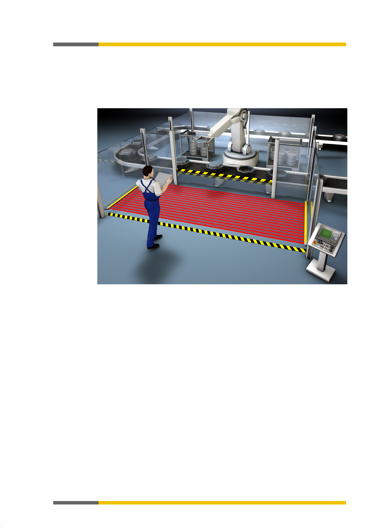
Illustration 1: Modular samosPRO safety control
The samosPRO system is characterized by the following system properties:
• Modular setup: 1 COMPACT module and up to 12 input/output expansion modules, each
of which has an overall width of 22.5 mm
• 16 to 116 inputs and 4 to 56 outputs
• Programmable using samosPLAN5+
• Can use up to 300 standard and application-specific logical blocks
• Standard logical blocks: AND, OR, NOT, XNOR, XOR
• Application-specific logical blocks: Emergency stop, two-hand, muting, operating mode
selection switch, reset, restart
• Can be integrated into different networks using gateways (e.g. ProfibusDP, CANopen,
Modbus/TCP, etc.)
The samosPLAN5+ programming software is available for configuring the control tasks.
You can find the programming software on the Internet or on CD:
• http://www.wieland-electric.com
or
samosPLAN5+ CD [ch. 13, p. 88]
•
Page 15
Product description
Wieland Electric GmbH | BA000966 | 07/2016 (Rev. C)
15
3.2
System setup
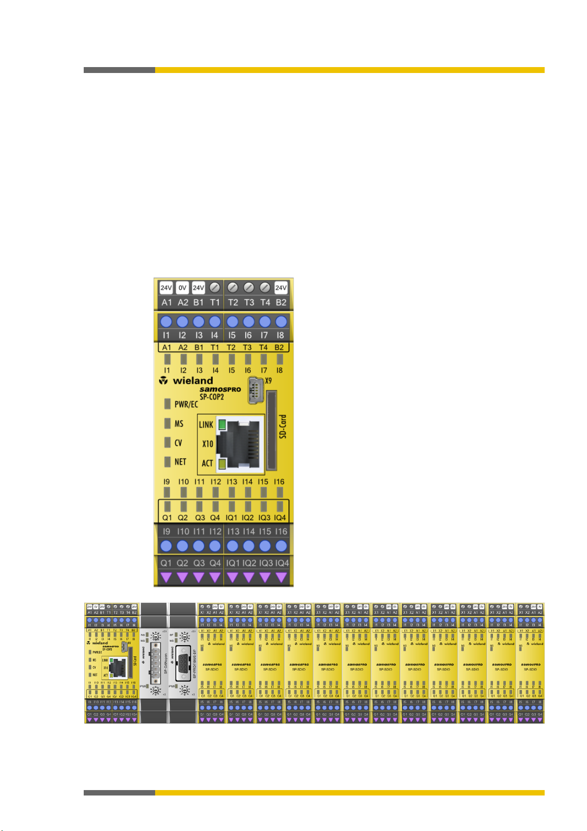
888341643
A samosPRO COMPACT system consists of the following modules and/or components:
• One COMPACT module
• One program removable storage
• The samosPLAN5+ programming software
• Up to two gateway modules
• Up to 12 additional SP-SDIO, SP-SDI and SP-DIO input/output modules
• In addition, SP-XX expansion modules can be used. This may be for example the SA-OR-Sx
relay output expansions or the SNS4084K standstill monitor. These modules are shown in
the report from samosPLAN5+ but cannot be logically connected to the modules of the
Samos PRO COMPACT system.
Further information on positioning this module: "samosPLAN5+ software" (BA000968)
manual, section "Special case: SP-XX expansion module"
Illustration 2: Example of a minimum samosPRO system setup with SP-COP2
Illustration 3: Maximum samosPRO system setup
Page 16
Product description
Wieland Electric GmbH | BA000966 | 07/2016 (Rev. C)
16
Type
Description
Inputs
Outputs
Logical
blocks
Max. occurrence
SP-COP1
Controller module
20 4 300
1×
SP-COP2-EN
Controller module
16-20 1)
4-81)
SP-COP2-ENI
Controller module
16-20 1)
4-81)
SP-SDIO
Input/output expansion
8 4 –
SP-SDI
Input expansion
8 – –
SA-OR-S1
Relay output expansion
– 4 –
4×2)
SA-OR-S2
Relay output expansion
– 2 –
8×2)
SP-DIO
Input/output expansion
81)
81) – 12×
SP-PROFIBUS-DP
PROFIBUS DP gateway
– – –
SP-CANopen
CANopen gateway
– – –
SP-EN-ETC
EtherCAT Gateway
– – –
Maximum 16 safe relay outputs
Table 2: Overview of modules (without program removable storage)
300 1×
12×
2×
1)
4 inputs or 4 outputs can be configured as an option
2)
Page 17

Product description
Wieland Electric GmbH | BA000966 | 07/2016 (Rev. C)
17
Available from module version
Feature / functionality
SP-COP1-x
SP-COP2-ENx
SP-COP2ENI-x
samosPLAN5
+
Modbus TCP
---
---
A-01
V1.0
Non-secure I/O (SP-DIO)
C-01.xx
C-01.xx
C-01.xx
V1.3
EtherCAT (SP-EN-ETC)
C-01.xx
C-01.xx
C-01.xx
V1.3
EtherNet/IP
---
---
D-01.xx
V1.4
Press functions1)
D-01.xx
D-01.xx
D-01.xx
V1.4 1) only available with module variants -P (example: SP-COP2-EN-P-x)
File menu
About
3.3
Version, compatibility, and features
840060811
There are various module versions and function packages for the samosPRO product family
that enable various functions. This section will give you an overview as to which module version, which function package, and/or which version of the samosPLAN5+ you will need to be
able to use a certain function or a certain device.
Table 3: Module and software versions required
Safe I/O (SP-SDIO, SP-SDI) A-01 A-01 A-01 V1.0
Profinet IO --- --- B-01.xx V1.2
Info
• You will find the module version on the type plate of the samosPRO modules.
• You can find the samosPLAN5+ version in the green
under
.
• You can obtain the latest version of the samosPLAN5+ on the Internet at
http://www.wieland-electric.de.
• Newer modules are backwards-compatible, which means that each module can be replaced with a module having a higher module version.
• You can find the date of manufacture for a device on the type plate in the S/N field in the
format <Product no.>yywwnnnnn (yy = year, ww = calendar week).
Page 18
Product description
Wieland Electric GmbH | BA000966 | 07/2016 (Rev. C)
18
P
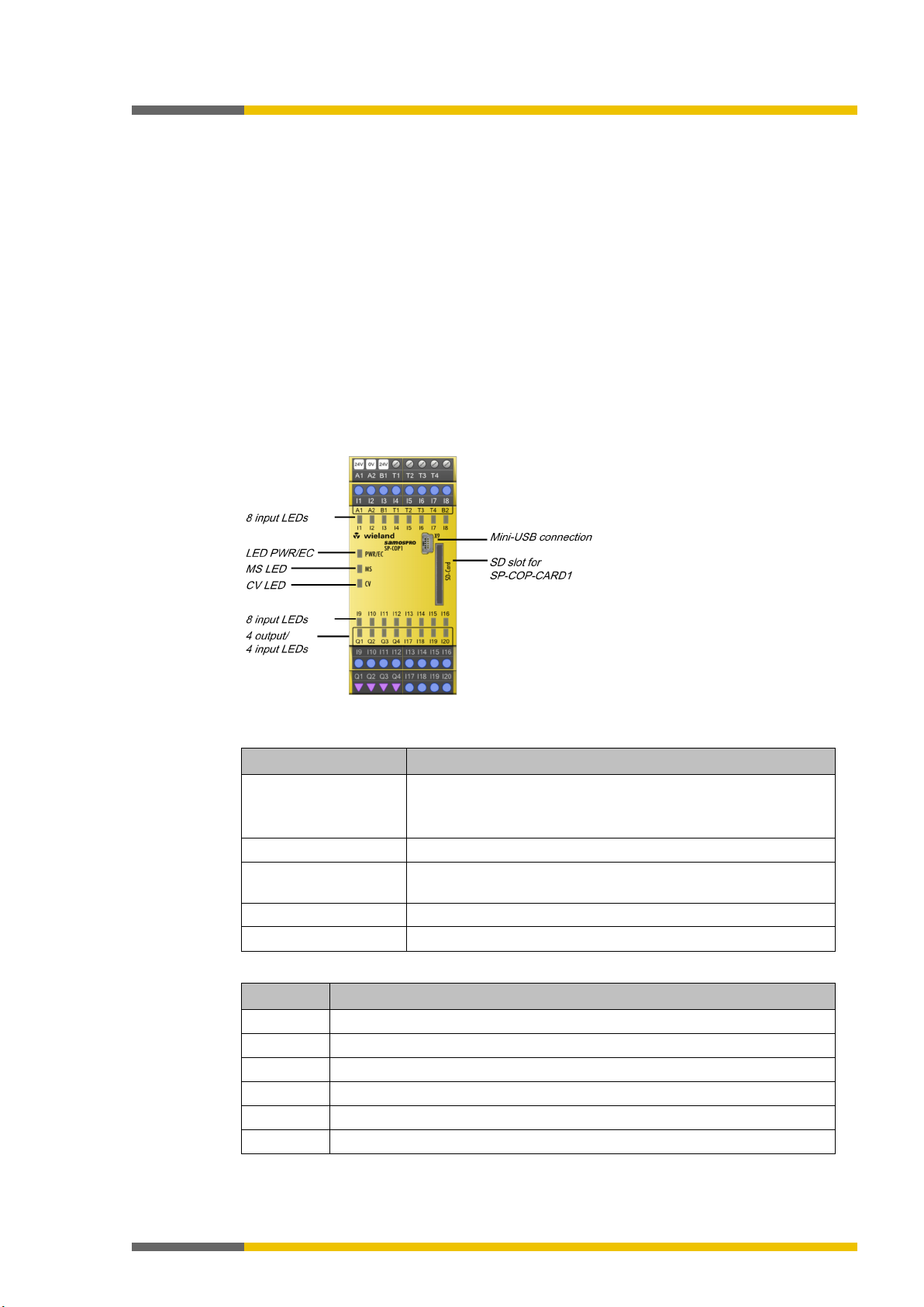
LED
Meaning
Flashing codes [ch. 10.3.1, p.
63]
MS
Display of the
Module state [ch. 10.3.1, p. 63]
Control project [ch. 10.3.1,
p. 63]
Input LED I1 to I20
State display of the
Inputs [ch. 10.3.1, p. 63]
Output LED Q1 to Q4
State display of the
Outputs [ch. 10.3.1, p. 63]
Pin
assignment
A1
24 V supply voltage for all modules, except for supply of outputs
A2
GND of supply voltage
I1 - I20
Safe, digital inputs
Q1 - Q4
Safe, digital outputs
B1
24 V supply voltage of outputs Q1 - Q4
T1 - T4
Test signal outputs
3.4
3.4.1
3.4.2
COMPACT module SP-COP1
888347531
Description
888349067
COMPACT module SP-COP1 is a central processing unit for the entire system in which all of
the signals are monitored and logically processed according to the configuration stored in the
SP-COP-CARD1 program removable storage. The module has safe inputs and outputs as well
as test signal outputs. The system outputs are switched as a result of the processing. The internal safety bus in this case serves as a data interface.
Module versions
In addition to the basic version there is the SP-COP1-
compact module.
This has additional press control functions.
Display elements, interfaces, and terminal description
888350603
Illustration 4: SP-COP1 display elements
Table 4: 4 LED displays
PWR/EC Display of the supply voltage state
Display of an error through various
CV Display of the verification state of the
Table 5: SP-COP1 pin assignment
Page 19
Product description
Wieland Electric GmbH | BA000966 | 07/2016 (Rev. C)
19
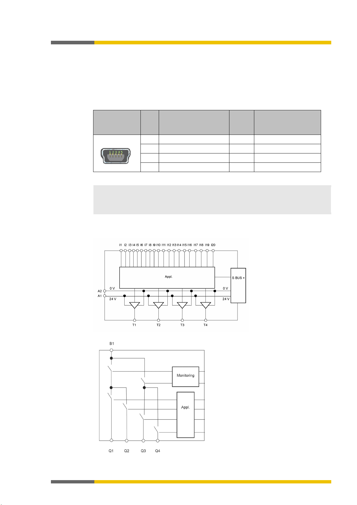
Connector/bushing
USB mini
Pin
Signal
Color
Assignment PC-side
1
+5V 2 - data
3
+ data
5
GND
NOTICE
• If the USB interface of the main module is permanently connected, then the maximum
main module, e.g. by using optocouplers.
3.4.3
USB interface
The main module has a mini-USB interface with the following functions:
• Transfer of the configuration from samosPLAN5+ to the program removable storage
• Reading of configuration from program removable storage in samosPLAN5+
• Diagnostics of the samosPRO systems with samosPLAN5+
Table 6: USB interface pin assignment
permissible cable length is 3 m.
• Avoid using ground loops between the USB interface GND and the A2 connection of the
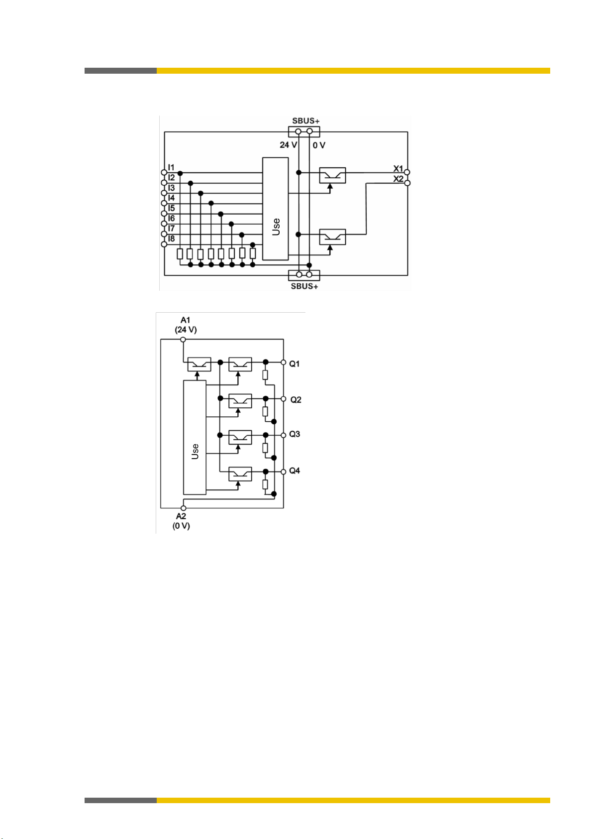
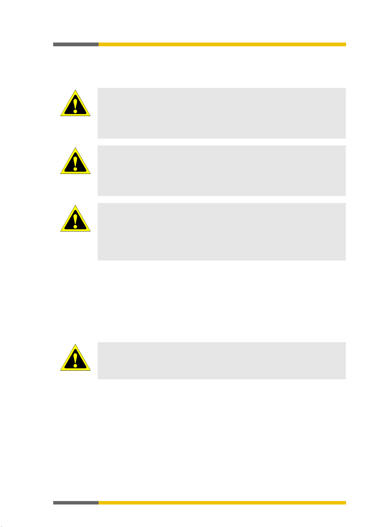
Internal circuits
888354955
Illustration 5: Inputs and test pulses at an SP-COP1 module
Illustration 6: Outputs at an SP-COP1 module
Page 20

Wieland Electric GmbH | BA000966 | 07/2016 (Rev. C)
20
• One SP-COPx has four test signal generators T1 – T4.
DC (after high) at inputs that are connected to test outputs are
Make note of this during wiring (e.g. through separate routing or protected lines)!
Switching off the test pulses at one of the two outputs of an output pair will switch off
the test pulses of the entire output pair!
Safety technology
reference values [ch. 12.2, p. 73]
Be sure to use protected or separate cabling!
off output, which will influence the capability of switching off the outputs.
Carry out cyclic tests when the test pulses at one or more safety outputs are deactivated!
• Restart the samosPRO system by switching off the supply voltage.
Edit
Activation of test pulses of this output
ATTENTION
Be sure to consider a potential brief switch to high with single-channel safety outputs!
Otherwise, there is a hazard for the operator of the machine.
3.4.4
3.4.5
3.4.6
ATTENTION
ATTENTION
Product description
Limited short-circuit detection in the input circuits
895385995-1
• Short-circuits between test signal generators of an SP-COPx are detected. Between different modules the short circuit detection is then only ensured if the test gaps of the test
signal generators are < 4 ms, the test periods ≥ 200 ms. In addition, the short circuit de-
tection is only ensured if no more than 9 modules (SP-SDI / SP-SDIO) have been plugged
in. Short-circuits after 24 V
detected independently of the length of the test gaps.
Deactivating the test pulses at the outputs of the SP-COP1
888356491
It is possible to deactivate the test pulses at one or more output pairs. The outputs are combined into two output pairs with the SP-COP1. Q1/Q2 and Q3/Q4. The test pulses each act upon
the two outputs of an output pair.
Deactivating the test pulses at one or more safety outputs of an SP-COP reduces the safety
parameters of both safety outputs of the respective output pair of this module.
• Be aware of this in order to ensure that your application corresponds to an appropriate
risk analysis and risk avoidance strategy.
• You can find more detailed information on the safety parameters here:
ATTENTION
ATTENTION
• If you deactivate the test pulses at one or more safety outputs, short-circuits at other
output circuits cannot be detected. This affects the safety function!
• In the event of a short-circuit after 24 V, it will no longer be possible to switch off the
output.
Furthermore, it will not be possible to prevent reverse current from going into a switched-
Once you deactivate the test pulses at one or more safety outputs, conduct the following
tests once a year:
• Switch off all of the safety outputs without test pulses simultaneously for at least one
second via the logic program of the COMPACT module.
OR
You will thus deactivate the test pulses at an output of the SP-COP1:
Connect an output element to the SP-COP module.
Using the right mouse key, click on the output element and select the
command in
the context menu.
Deactivate the
option. The test pulses of this output will be switched off. A corresponding note will be displayed in the hardware configuration area under the respective SP-COP module.
Single-channel use of outputs on the SP-COP1
888357515
In the event of an internal hardware error, single-channel safety outputs can switch to high
once for 10 ms after the error has been detected.
• Consider this during your risk analysis and reduction strategy.
Page 21
Product description
Wieland Electric GmbH | BA000966 | 07/2016 (Rev. C)
21
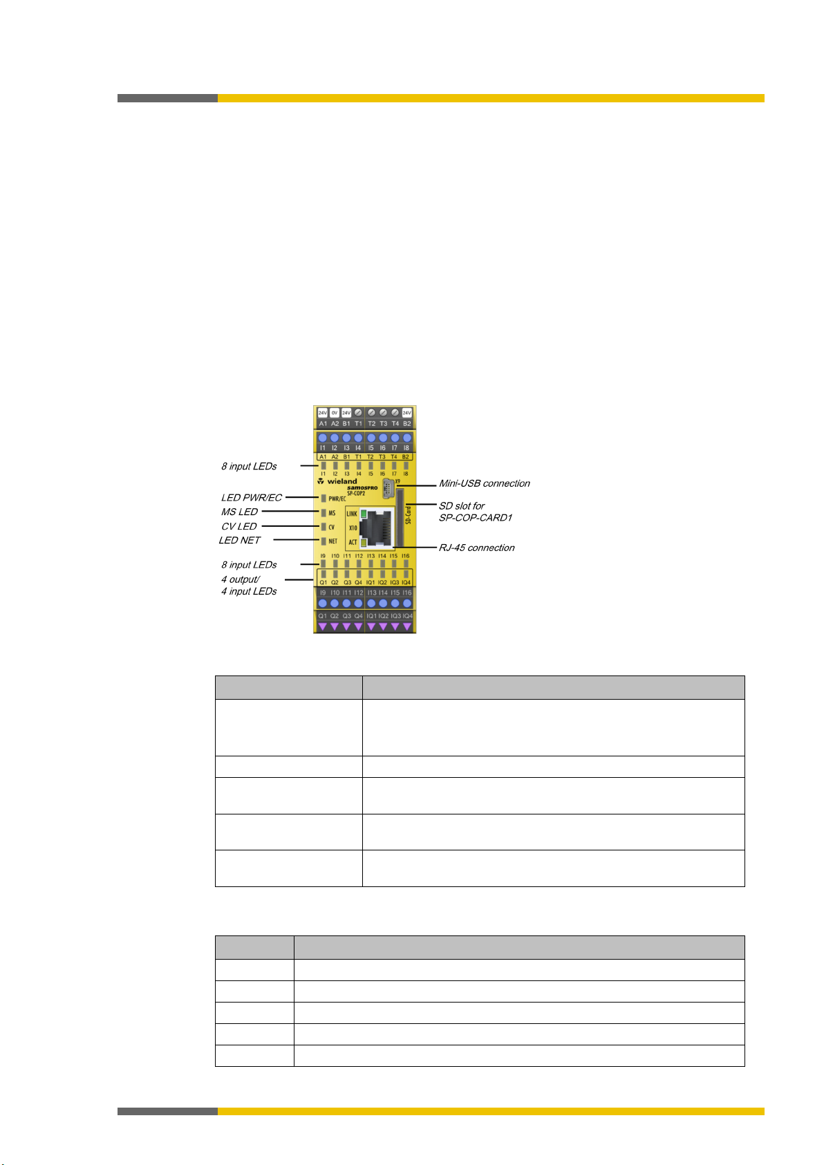
P
LED
Meaning
Flashing codes [ch. 10.3.1, p.
63]
MS
Display of the
Module state [ch. 10.3.1, p. 63]
Control project [ch. 10.3.1,
p. 63]
to IQ4
Pin
assignment
A2
GND of supply voltage
Q1 - Q4
Safe, digital outputs
IQ1 - IQ4
Safe, digital inputs or outputs (configurable through samosPLAN5+)
3.5
3.5.1
3.5.2
COMPACT module SP-COP2-EN
888359051
Description
888360587
COMPACT module SP-COP2-EN is the central processing unit for the entire system in which all
of the signals are monitored and logically processed according to the configuration stored in
the SP-COP-CARD1 program removable storage. The module has safe inputs and outputs as
well as test signal outputs. The system outputs are switched as a result of the processing. The
internal safety bus in this case serves as a data interface.
Module versions
In addition to the basic version there is the SP-COP2-EN-
compact module.
This has additional press control functions.
Display elements, interfaces, and terminal description
888362123
Illustration 7: SP-COP2-EN display elements
Table 7: SP-COP 2 LED displays
PWR/EC Display of the supply voltage state
Display of an error through various
CV Display of the verification state of the
Input LED I1 to I16, IQ1
Output LED Q1 to Q4,
State display of the
State display of the
Inputs [ch. 10.3.1, p. 63]
Outputs [ch. 10.3.1, p. 63]
IQ1 to IQ4
Table 8: Pinout SP-COP2
A1 24 V supply voltage for all modules, except for supply of outputs
I1 - I16 Safe, digital inputs
Page 22
Product description
Wieland Electric GmbH | BA000966 | 07/2016 (Rev. C)
22
Pin
assignment
B1
24 V supply voltage of outputs Q1 - Q4
B2
24 V supply voltage of configurable outputs IQ1 - IQ4
T1 - T4
Test signal outputs
Connector/bushing
USB
Pin
Signal
1
+5V 2 - data
3
+ data
5
GND
NOTICE
• If the USB interface of the main module is permanently connected, then the maximum
main module, e.g. by using optocouplers.
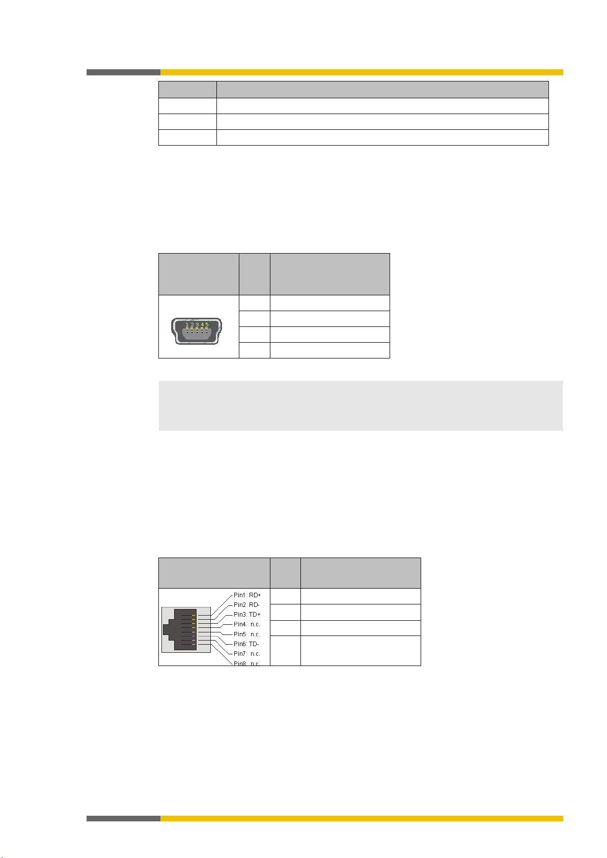
Connector/bushing
RJ45
Pin
Signal (Auto MDI-X)
1
RD+ / TD+
2
RD- / TD-
3
TD+ / RD+
USB interface
The main module has a mini-USB interface with the following functions:
• Transfer of the configuration from samosPLAN5+ to the program removable storage
• Reading of configuration from program removable storage in samosPLAN5+
• Diagnostics of the samosPRO systems with samosPLAN5+
Table 9: USB interface pin assignment
permissible cable length is 3 m.
• Avoid using ground loops between the USB interface GND and the A2 connection of the
Ethernet interface
The main module has an Ethernet interface with the following functions:
• Transfer of the configuration from samosPLAN5+ to the program removable storage
• Reading of configuration from program removable storage in samosPLAN5+
• Diagnostics of the samosPRO systems with samosPLAN5+
• Continuous diagnostics of the samosPRO system via a connected PLC.
Table 10: RJ 45 bushing pin assignment
6 TD- / RD-
The device itself detects which cable type, patch cable or cross-link cable, is being used (Auto
MDI-X), which is why the pin assignment does not matter with regard to the RD or TD signals.
Page 23
Wieland Electric GmbH | BA000966 | 07/2016 (Rev. C)
23
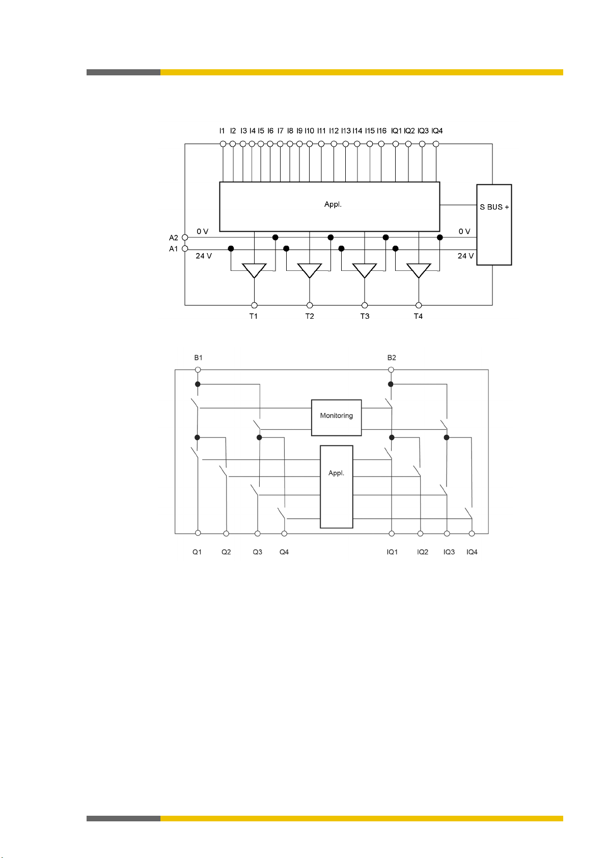
Internal circuits
3.5.3
888365195
Product description
Illustration 8: Inputs and test pulses at an SP-COP2-EN module
Illustration 9: Outputs at an SP-COP2-EN module
Page 24

Wieland Electric GmbH | BA000966 | 07/2016 (Rev. C)
24
• One SP-COPx has four test signal generators T1 – T4.
DC (after high) at inputs that are connected to test outputs are
Make note of this during wiring (e.g. through separate routing or protected lines)!
Switching off the test pulses at one of the two outputs of an output pair will switch off
the test pulses of the entire output pair!
Safety technology
reference values [ch. 12.2, p. 73]
ATTENTION
Be sure to use protected or separate cabling!
output.
Carry out cyclic tests when the test pulses at one or more safety outputs are deactivated!
• Restart the samosPRO system by switching off the supply voltage.
Edit
Activation of test pulses of this output
3.5.4
3.5.5
ATTENTION
ATTENTION
Product description
Limited short-circuit detection in the input circuits
895385995-2
• Short-circuits between test signal generators of an SP-COPx are detected. Between different modules the short circuit detection is then only ensured if the test gaps of the test
signal generators are < 4 ms, the test periods ≥ 200 ms. In addition, the short circuit de-
tection is only ensured if no more than 9 modules (SP-SDI / SP-SDIO) have been plugged
in. Short-circuits after 24 V
detected independently of the length of the test gaps.
Deactivating the test pulses at the outputs of the SP-COP2
888366731
It is possible to deactivate the test pulses at one or more output pairs. The outputs are combined into four output pairs with the SP-COP2: Q1/Q2, Q3/Q4, IQ1/IQ2, and IQ3/IQ4. The test
pulses each act upon the two outputs of an output pair.
Deactivating the test pulses at one or more safety outputs of an SP-COP reduces the safety
parameters of both safety outputs of the respective output pair of this module.
• Be aware of this in order to ensure that your application corresponds to an appropriate
risk analysis and risk avoidance strategy.
• You can find more detailed information on the safety parameters here:
ATTENTION
• If you deactivate the test pulses at one or more safety outputs, short-circuits at other
output circuits cannot be detected. This affects the safety function!
• In the event of a short-circuit after 24 V, it will no longer be possible to switch off the
Once you deactivate the test pulses at one or more safety outputs, conduct the following
tests once a year:
• Switch off all of the safety outputs without test pulses simultaneously for at least one
second via the logic program of the COMPACT module.
OR
You will thus deactivate the test pulses at an output of the SP-COP2:
Connect an output element to the SP-COP module.
Using the right mouse key, click on the output element and select the
command in
the context menu.
Deactivate the
option. The test pulses of this output will be switched off. A corresponding note will be displayed in the hardware configuration area under the respective SP-COP module.
Page 25

Product description
Wieland Electric GmbH | BA000966 | 07/2016 (Rev. C)
25
ATTENTION
Be sure to consider a potential brief switch to high with single-channel safety outputs!
Otherwise, there is a hazard for the operator of the machine.
3.5.6
Single-channel use of outputs on the SP-COP2
888368267
In the event of an internal hardware error, single-channel safety outputs can switch to high
once for 10 ms after the error has been detected.
• Consider this during your risk analysis and reduction strategy.
Page 26

Product description
Wieland Electric GmbH | BA000966 | 07/2016 (Rev. C)
26
P
NOTICE
• The data stored in the SP-COP-CARD1 program removable storage will be retained even
a module, make sure that the program removable storage is inserted into
dules.
3.6
3.6.1
3.6.2
3.7
3.7.1
COMPACT module SP-COP2-ENI
888369803
Description
888371339
COMPACT module SP-COP2-ENI has the same functionality and has the same connections
and the same displays as the
SP-COP2-EN [ch. 3.5, p. 21]
.
In addition, this module has the following gateway functionality on-board:
• Modbus/TCP interface
• PROFINET IO interface
• EtherNet/IP interface
Module versions
In addition to the basic version there is the SP-COP2-ENI-
compact module.
This has additional press control functions.
Display elements, error codes, and terminal description
888372363
The displays of the MS and CV LEDs as well as the terminal assignment of the USB and Ethernet interface are identical to those for the SP-COP2-EN controller module.
Further information:
Display elements, interfaces, and terminal description [ch. 3.5.2, p. 21]
COMPACT SP-COP-CARD1 removable storage
888373387
Description
888374923
The system configuration of the entire samosPRO system is stored in the SP-COP-CARD1 program removable storage. This has the advantage that the samosPRO system does not have to
be reconfigured when modules are replaced.
The COMPACT SP-COP-CARD1 removable storage is an SD card that is produced and formatted specially for use in COMPACT modules.
if the supply voltage is interrupted.
• When replacing
the appropriate COMPACT module. Mark all of the connection lines and plug connectors
on the samosPRO system clearly to prevent mixups.
• Commonly available SD cards cannot be used/inserted in samosPRO and COMPACT mo-
Page 27
Product description
Wieland Electric GmbH | BA000966 | 07/2016 (Rev. C)
27
Limited short-circuit detection in the input circuits
Make note of this during wiring (e.g. through separate routing or protected lines)!
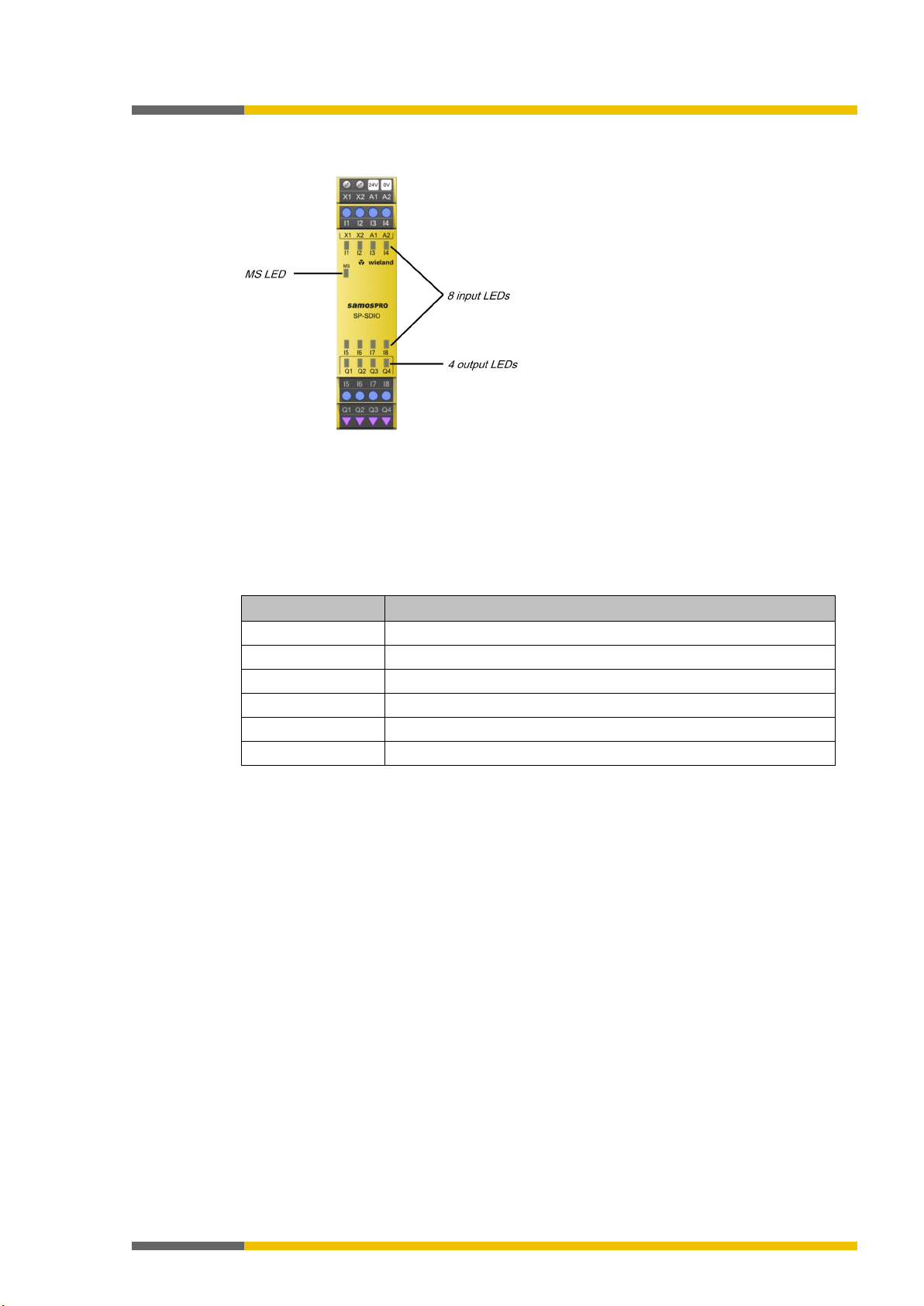
NOTICE
• The LEDs of inputs I1 to I8 indicate the state of the inputs at an update rate of about 64
ms.
3.8
3.8.1
SP-SDIO input/output expansion module
888376459
Description
888377995
The SP-SDIO module is an input/output expansion with eight safe inputs and four safe outputs.
It has two test signal generators: one for test output X1 and one for test output X2.
The SP-SDIO module offers the following functions:
• Monitoring of connected safety devices
For further information:
Connecting devices [ch. 4, p. 37]
• Forwarding the input information to the main module
• Receipt of control signals from the main module and corresponding switching of outputs
• Fast shut-off: Direct switch-off of the actuators connected on the module. This results in a
significant reduction in the response time of the entire system. Only 8 ms are needed in
the response times of the devices at the inputs and outputs in order to switch-off the outputs. The runtimes on the internal SBUS+ bus and the Logic Execution Time do not play
any role in this case.
Further information:
samosPRO system response times [ch. 12.1, p. 70]
• Activating or deactivating test pulses at the outputs (Q1–Q4) with firmware version V2.00.0
and higher.
Module SP-SDIO cannot be operated alone; it always requires an SP-COP COMPACT module
(see "samosPLAN5+" programming software).
It is possible to use multiple SP-SDIO84 modules simultaneously (see
15]
). The voltage of the internal logic and the test outputs is supplied via the system connector
System setup [ch. 3.2, p.
and the internal SBUS+ bus. The voltage of the Q1–Q4 outputs of the SP-SDIO must be supplied directly via A1/A2 at the respective module.
ATTENTION
• One SP-SDIO has two test signal generators, X1 and X2.
• Short-circuits between test signal generators of an SP-SDI or SP-SDIO expansion module
are detected. Between different modules the short circuit detection is then only ensured
if the test gaps of the test signal generators are < 4 ms, the test periods ≥ 200 ms and no
more than 9 modules (SP-SDI / SP-SDIO) have been plugged in. Short-circuits after 24
V DC (after high) at inputs that are connected to test outputs are detected independently
of the length of the test gaps.
Page 28
Wieland Electric GmbH | BA000966 | 07/2016 (Rev. C)
28
Display elements and terminal assignment
Terminal
assignment
X1/X2
Test output 1 / test output 2
I1–I4
Inputs 1 to 4
A1
24 V
A2
GND
I5–I8
Inputs 5 to 8
Q1–Q4
Outputs 1 to 4
3.8.2
888379019
Product description
Illustration 10: SP-SDIO display elements
Flashing codes
Further information:
SDI) [ch. 10.3.2, p. 65]
Terminal assignment
Table 11: SP-SDIO terminal assignment reference
Device state and LED displays in the expansion modules (SP-SDIO, SP-
Page 29
Product description
Wieland Electric GmbH | BA000966 | 07/2016 (Rev. C)
29
3.8.3
Internal circuits
888388363
Illustration 11: Internal SP-SDIO circuits: Safe inputs and test outputs
Illustration 12: Internal SP-SDIO circuits: Safety outputs
Page 30
Wieland Electric GmbH | BA000966 | 07/2016 (Rev. C)
30
Deactivating the test pulses at any output reduces the safety parameters of all outputs!
Technical data [ch.
12, p. 70]
Be sure to use protected or separate cabling!
off output, which will influence the capability of switching off the outputs.
Carry out cyclic tests when the test pulses at one or more safety outputs are deactivated!
• Restart the samosPRO system by switching off the supply voltage.
Edit
Activation of test pulses of this output
ATTENTION
Be sure to consider a potential brief switch to high with single-channel safety outputs!
chine.
3.8.4
3.8.5
ATTENTION
ATTENTION
Product description
Deactivating the test pulses at the outputs of the SP-SDIO
888394763
With firmware version V2.00.0 and higher, it is possible to deactivate the test pulses at one or
more outputs of SP-SDIO84-P1 modules.
Deactivating the test pulses at one or more safety outputs of an SP-SDIO module reduces the
safety parameters of all Q1 to Q4 safety outputs of this module.
• Be aware of this in order to ensure that your application corresponds to an appropriate
risk analysis and risk avoidance strategy.
• You can find more detailed information on the safety parameters here:
• If you deactivate the test pulses at one or more safety outputs, short-circuits at other
output circuits cannot be detected. This affects the safety function!
• In the event of a short-circuit after 24 V, it will no longer be possible to switch off the
output.
Furthermore, it will not be possible to prevent reverse current from going into a switched-
ATTENTION
Once you deactivate the test pulses at one or more safety outputs, conduct the following
tests once a year:
• Switch off all of the safety outputs without test pulses simultaneously for at least one
second via the logic program of the COMPACT module.
OR
You will thus deactivate the test pulses at an output of the SP-SDIO:
Connect an output element to the SP-SDIO module.
Using the right mouse key, click on the output element and select the
command in
the context menu.
Deactivate the
option. The test pulses of this output will be switched off. A corresponding note will be displayed in the hardware configuration area under the respective SP-SDIO module.
Single-channel use of outputs on the SP-SDIO
888395787
In the event of an internal hardware error, single-channel safety outputs (Q1 to Q4) can
switch to high once for 10 ms after the error has been detected. Consider this during your
risk analysis and reduction strategy. Otherwise, there is a hazard for the operator of the ma-
Page 31

Wieland Electric GmbH | BA000966 | 07/2016 (Rev. C)
31
Limited short-circuit detection in the input circuits
DC (after High) at inputs that are connected to test outputs are detected independently
Make note of this during wiring (e.g. through separate routing or protected lines)!
3.9
3.9.1
ATTENTION
Product description
SP-SDI input/output expansion module
888397323
Description
888398859
The SP-SDI module is an input expansion with eight safe inputs. If fulfills the following tasks:
• Monitoring of connected sensors
For further information:
Connecting devices [ch. 4, p. 37]
• Forwarding of input information to the COMPACT module
Module SP-SDI cannot be operated alone; it always requires an SP-COP COMPACT module
(see "samosPLAN5+" programming software).
It is possible to use multiple SP-SDI modules simultaneously (see
15]
). The voltage of the internal logic and the test outputs is supplied via the program remo-
vable storage and the internal SBUS+.
• One SP-SDI has two test signal generators. One test signal generator is responsible for
the odd-numbered test outputs (X1, X3, X5, and X7), while the other is responsible for
the even-numbered test outputs (X2, X4, X6, and X8).
• Short-circuits between test signal generators of an SP-SDI or SP-SDIO expansion module
are detected. Between different modules the short circuit detection is then only ensured
if the test gaps of the test signal generators are < 4 ms, the test periods ≥ 200 ms and no
more than 9 modules (SP-SDI / SP-SDIO) have been plugged in. Short-circuits after 24
V
of the length of the test gaps.
• Please ensure that the odd-numbered test outputs (X1, X3, X5, and X7) at the SP-SDI are
connected to a common test signal generator and that the even-numbered test outputs
(X2, X4, X6, and X8) are connected to another common test signal generator. Therefore,
short-circuits between the odd-numbered test outputs (X1, X3, X5, and X7) cannot be detected. The same applies accordingly to the even-numbered test outputs (X2, X4, X6, and
X8).
System setup [ch. 3.2, p.
Page 32

Product description
Wieland Electric GmbH | BA000966 | 07/2016 (Rev. C)
32
NOTICE
• The LEDs of inputs I1 to I8 indicate the state of the inputs at an update rate of about 64
ms.
Terminal
assignment
X1/X3
Test signal 1
X2/X4
Test signal 2
I1 – I4
Inputs 1 to 4
X5/X7
Test signal 1
3.9.2
3.9.3
Display elements and terminal assignment
888399883
Illustration 13: SP-SDI display elements
Flashing codes
Further information:
SDI) [ch. 10.3.2, p. 65]
Terminal assignment
Table 12: SP-SDI terminal assignment reference
I5 – I8
X6/X8 Test signal 2
Internal circuits
888402571
Device state and LED displays in the expansion modules (SP-SDIO, SP-
Inputs 5 to 8
Illustration 14: Internal SP-SDI circuits: Safety inputs and test outputs
Page 33

Product description
Wieland Electric GmbH | BA000966 | 07/2016 (Rev. C)
33
3.10
3.10.1
SP-DIO input/output expansion module
1126263051
Description
1126271883
The SP-DIO module is an input/output expansion with four non-secure inputs, four non-secure
outputs and 4 non-secure input/output combinations whose function is configured using the
samosPLAN5+ software.
The SP-DIO module offers the following functions:
• Monitoring of connected devices and sensors
For further information:
Connecting devices [ch. 4, p. 37]
• Forwarding the input information to the main module
• Receipt of control signals from the main module and corresponding switching of outputs
The SP-DIO module cannot be operated alone; it always requires an SP-COP COMPACT module (see "samosPLAN5+" programming software).
It is possible to use multiple SP-DIO modules simultaneously (see
15]
). The voltage of the internal logic is supplied via the system connector and the internal
System setup [ch. 3.2, p.
SBUS+ bus. The voltage of the Y1–Y4 and IY5–IY8 outputs of the SP-DIO must be supplied directly via A1/A2 at the respective module.
Refresh rate
The LEDs of the I1–I4 inputs and the Y1–Y4 outputs or the inputs/outputs combination show
the state with a refresh rate of approx. 4 ms.
Restricted selection of inputs
Only the single-channel inputs are available to be selected in the configuration for the SP-DIO
expansion module, for example:
Illustration 15: Single-channel inputs for the 'SP-DIO' expansion module
Page 34

Product description
Wieland Electric GmbH | BA000966 | 07/2016 (Rev. C)
34
Terminal
assignment
A1
24 V
A2
GND
I1–I4
non-secure inputs 1 to 4
IY5–IY8
non-secure inputs/outputs combination 5 to 8
Y1–Y4
non-secure outputs 1 to 4
3.10.2
Display elements and terminal assignment
1126324875
Illustration 16: SP-DIO display elements
Flashing codes
Further information:
10.3.3, p. 65]
Terminal assignment
Table 13: SP-DIO terminal assignment reference
Device state and LED displays of the expansion module (SP-DIO) [ch.
Page 35

Wieland Electric GmbH | BA000966 | 07/2016 (Rev. C)
35
Internal circuits
3.10.3
1126341003
Product description
Illustration 17: Internal switching circuit of the SP-DIO: non-secure inputs
Illustration 18: Internal switching circuit of the SP-DIO: non-secure outputs
Illustration 19: Internal switching circuit of the SP-DIO: non-secure inputs/outputs combination
Page 36

Product description
Wieland Electric GmbH | BA000966 | 07/2016 (Rev. C)
36
ATTENTION
Use of the IY5–IY8 inputs/outputs
When using the combination connections as input, the signal input voltage to IY5–IY8 may
never be greater than the supply voltage to A1/A2.
Page 37

Connecting devices
Wieland Electric GmbH | BA000966 | 07/2016 (Rev. C)
37
Loss of safety function due to incorrect configuration!
The configuration of the safety application must be precisely adapted to the circumstances of the system or machine to be monitored.
off time of the connected sensors must be longer than the
the sensors.
Protect single-channel inputs against short-circuits and cross-connections!
Because of this, note the following specifications for single-channel signals with test pulses:
This must be noted in particular for the following inputs:
4
Connecting devices
888405259
This section describes the connection of safety sensors and actuators to the samosPRO system and provides setup information for selected functions.
The samosPRO system supports applications up to Performance Level PL e (as per EN ISO
13849-1) and up to Safety Integrity Level SIL CL3 (as per EN 62061).
The level of safety actually achieved depends on the external wiring, the implementation of the
wiring, the parameterization, the selection of the safety sensors, and their arrangement on the
machine. To this end, consider all of the required boundary conditions and evaluate them, for
example, in a Failure Modes and Effects Analysis (FMEA).
You can find additional information to be noted during the electrical installation here:
installation [ch. 7, p. 57]
Electrical
ATTENTION
ATTENTION
Important information
Carefully plan and implement configuration!
• Check to ensure that the configured safety application monitors the machine or system
as you have planned and whether the safety of a configured application is being ensured
at all times. This must be ensured in all operating modes and for all sub-applications.
Document the results of this test!
• Be sure to note the instructions for commissioning and daily testing in the operating instructions for the safety equipment integrated into the safety application.
• Note the warning information and function descriptions for the safety equipment connected to the safety control. When in doubt, contact the respective manufacturer of the safety equipment.
• Note that the minimum switchexecution time of the logic function (for further information, see the "samosPLAN5+
Software" manual (BA000968), Time values and logic execution time).
In this way you will ensure that the samosPRO system can detect the switching of sensors. The minimum switch-off time of sensors is typically listed in the technical data for
When a short-circuit to high occurs at a single-channel input with test pulses that were previously low, this signal can then look like a pulse for the logic. A short-circuit to high means
that the signal is first to high and then is back to low after the error detection time. A pulse
can be generated due to the error detection.
• If the short-circuit to high occurs at a single-channel input with test pulses that was previously high, this signal for the logic then looks like a delayed falling edge (transition from
high to low).
• When a single-channel input is used and an unexpected pulse or a delayed falling edge
(high to low) at this input can lead to a state causing a risk, then you must undertake the
following measures:
– Protected cabling for the signal in question (in order to prevent cross-connections with
other signals)
– No cross-connection detection, i.e. no connection with a test output
– Input reset at the function block reset
– Input restart at the function block restart
– Input restart at the function blocks for press applications (eccentric press contact mo-
nitor,
– contact monitor for universal presses, cycle mode, press setup, single stroke monito-
ring, press automatic mode)
Page 38

Connecting devices
Wieland Electric GmbH | BA000966 | 07/2016 (Rev. C)
38
NOTICE
• When using an odd-numbered test output, odd-numbered inputs must be used, while
You have to use the test outputs of the module at which the device to be tested has been
connected.
– Input override at a function block for muting
– Input reset at a function block for valve monitoring
– Resetting of inputs to zero and setting at a start value on an event counter function
Report function in samosPLAN5+
After project planning, you will receive the following documentation in samosPLAN5+ under
"Info -> Report":
• Logic report
• List of parts
• Wiring information
Table 14: Excerpt from exemplary documentation in samosPLAN5+
block
even-numbered inputs must be used when using an even-numbered test output.
•
Page 39

Connecting devices
Wieland Electric GmbH | BA000966 | 07/2016 (Rev. C)
39
Electrical connection: Example from samosPLAN5+
without testing
Channel 2: Contact between 24 V and I4
Function
Info
Testing
Possible
tion/cascading
max. line resistance of 100 Ω
NOTICE
You can find additional information in the operating instructions for the SNH emergency stop
button.
Electrical connection: Example from samosPLAN5+
Channel 2: Contact between Ub and I4
Channel 2: Contact between T2 and I6
4.1
4.1.1
4.1.2
Safety command devices and electromechanical safety switches
888411275
Emergency stop buttons (e.g. SNH series)
888412811
Table 15: Connection
Single-channel,
Contact between 24 V and I1
Single-channel,
Contact between T2 and I2
with testing
Two-channel,
without testing
Two-channel,
with testing
Channel 1: Contact between 24 V and I3
Channel 1: Contact between T1 and I5
Channel 2: Contact between T2 and I6
The pre-configured two-channel emergency stop buttons in samosPLAN5+ have equivalent
switching contacts. In order to implement two-channel complementary switching contacts,
you can find corresponding elements in the element window under the group of potential-free
contacts.
Table 16: Functions
Series connec-
Max. number of emergency stop buttons switched in series: note
Synchronous time 4 ms to 30 ms
Electromechanical safety switch without lock (e.g. SMS series)
888420491
Table 17: Electromechanical safety switch connection
Single-channel,
Contact between Ub and I1
without testing
Single-channel,
Contact between T2 and I2
with testing
Two-channel,
Channel 1: Contact between Ub and I3
without testing
Two-channel,
Channel 1: Contact between T1 and I5
with testing
Page 40

Connecting devices
Wieland Electric GmbH | BA000966 | 07/2016 (Rev. C)
40
Electrical connection: Example from samosPLAN5+
Inductor at Q1
Inductor at Q3
Inductor at Q1
Function
Info
tion/cascading
determined by the max. line resistance of 100 Ω.
Synchronous time
4 ms–30 s
NOTICE
You can find additional information in the operating instructions for the electromechanical
safety switches.
4.1.3
Electromechanical safety switch with lock (e.g. SIN series)
888428171
Table 18: Connection of locks
Single-channel,
without testing
Contact between Ub and I1
Single-channel,
with testing
Contact between T2 and I2
Two-channel,
without testing
Inductor at Q2
Channel 1: Contact between Ub and I3
Channel 2: Contact between Ub and I4
Two-channel,
with testing
Channel 1: Contact between T1 and I1
Channel 2: Contact between T2 and I2
Table 19: Functions with electromechanical safety switches and locks
Testing Possible
Series connec-
The max. number of emergency stop buttons switched in series is
Page 41

Connecting devices
Wieland Electric GmbH | BA000966 | 07/2016 (Rev. C)
41
Electrical connection: Example from samosPLAN5+
NC 2: between Ub and I2
NO 2: between Ub and I4
Function
Info
Series connection
Not possible
Synchronous time
4 ms–30 s
NOTICE
You can find additional information in the operating instructions for the respective devices.
4.1.4
Enable switch
888442507
Table 20: Enable switch connection
2 positions,
NC 1: between Ub and I1
without testing
2 positions,
with testing
3 positions,
without testing
NC 1: between T1 and I3
NC 2: between T2 and I4
NC 1: between Ub and I1
NC 2: between Ub and I2
NO 1: between Ub and I3
3 positions,
with testing
NC 1: between Ub and I5
NC 2: between Ub and I6
NO 1: between T1 and I7
Table 21: Functions
NO 2: between T2 and I8
Testing Possible
Page 42

Connecting devices
Wieland Electric GmbH | BA000966 | 07/2016 (Rev. C)
42
Electrical connection: Example from samosPLAN5+
NOTICE
You can find additional information in the operating instructions for two-hand control.
4.1.5
4.1.5.1
4.1.5.2
Two-hand control
888450187
Table 22: Two-hand control connection
Type IIIA,
without tes-
Channel 1: Contact between 24 V and I1
Channel 2: Contact between 24 V and I2
ting
Type IIIC,
without testing
NO (normally open contact) between 24 V
and I6 (I8)
NC (normally closed contact) between 24
V and I5 (I7)
888454539
Type IIIA
With type IIIA, two equivalent inputs (make NC contacts for both two-hand buttons) are monitored.
A valid input signal is only generated when the ON state (H level) is present at both inputs
within a time of 0.5 seconds (synchronous change, both two-hand buttons actuated) and both
were previously in the OFF state (L level).
888456075
Type IIIC
With type IIIC, two pairs of equivalent inputs (NC (normally closed contact)/NO (normally open
contact) contact pairs for both two-hand buttons) are monitored.
A valid input signal is only generated when the ON state (H/L level) is present at both inputs
within a time of 0.5 seconds (synchronous change, both two-hand buttons actuated) and both
were previously in the OFF state (L/H level).
Page 43

Connecting devices
Wieland Electric GmbH | BA000966 | 07/2016 (Rev. C)
43
Electrical connection: Example from samosPLAN5+
T2 and I2
T2 and I2
Function
Info
Parallel connection
Possible
Series connection
Possible
ATTENTION
Make sure that the switch-off condition is sufficient!
NOTICE
You can find additional information in the operating instructions for the safety mats.
4.1.6
4.1.7
Safety mats and bumper
888457611
Table 23: Safety mats connection
Short-circuit-forming
safety mat in 4-conductor
technology, at test output
Short-circuit-forming
multi-safety mat in 4conductor technology, at
test output
Table 24: Function of safety mats
Channel 1: Contact between
T1 and I1
Channel 2: Contact between
Channel 1: Contact between
T1 and I1
Channel 2: Contact between
The actuation period for safety mats and bumper must be at least as high as the maximum
value for the "test period" of both test outputs used in order to ensure that the switch-off
condition will be detected and that a sequencing error will not occur.
Diode pairs for safety mats
888461963
In order to connect multiple short-circuit safety mats to an SP-COP, SP-SDI, or SP-SDIO module, you have to use the following Wieland terminal block:
Type: WKFN 2.5 E/35 GO-URL
Order No.: 56.703.8755.9
The two internal diodes of this terminal block have a common anode that has to be connected
to a test output (Tn or X) of the SP-COP, SP-SDI, or SP-SDIO module.
In order to connect to independent safety mats, you will need two terminal blocks.
Illustration 20: Block diagram of the internal wiring WKFN 2.5 E/35 GO-URL
Page 44

Connecting devices
Wieland Electric GmbH | BA000966 | 07/2016 (Rev. C)
44
Electrical connection: Example from samosPLAN5+
between 24 V and I2
Function
Info
Testing
Possible
NOTICE
• Operating mode selection switches without test pulses enable 2 to 8 operating modes;
numbered inputs (I2, I4,
selection switches.
Function
Info
Testing
Possible
(BA000968)
4.1.8
4.1.9
Mode selection switch
888464651
Operating mode selection
switch (1 from 2) to 24 V
Channel 1: Contact
between 24 V and I1
Channel 2: Contact
Operating mode selection
switch (1 from 2)
to test
output
Channel 1: Contact
between T1 and I3
Channel 2: Contact
between T2 and I4
operating mode selection switches with test pulses enable 2 to 4 operating modes.
• When wiring the tested operating mode selection switches, note that when using an oddnumbered test output (X1, X3, X5, X7), odd-numbered inputs (I1, I3, I5, I7) must be used;
when using an even-numbered test output (X2, X4, X6, X8), evenI6, I8) must also be used.
• You can find additional information in the operating instructions for the operating mode
Potential-free contacts
888469003
The samosPLAN5+ software provides a series of potential-free contacts for "free" designing of
contact elements. In this manner, you can implement different NO (normally open contact)/NC
(normally closed contact) combinations with and without testing. In addition, there are elements for a start and stop button, reset button, and device monitoring (EDM).
Table 25: Function of potential-free contacts
Series connection Possible
Discrepancy time Further information: "samosPLAN5+ Software" manual
Page 45

Connecting devices
Wieland Electric GmbH | BA000966 | 07/2016 (Rev. C)
45
Electrical connection: Example from samosPLAN5+
Channel 2: Contact between T2 and I4
Electrical connection: Example from samosPLAN5+
NC contact between T2 and I2
Function
Info
Testing
Possible
tion/cascading
test pulse time
Discrepancy time
Preset at 1500 ms
NOTICE
You can find additional information in the operating instructions for the magnetic safety switches.
Electrical connection: Example from samosPLAN5+
Output A at I1
OSSD2 at I4
Function
Info
Inductive switches (serial):
and the correct setting of the test
Inductive switch: No cascading possible
NOTICE
You can find additional information in the operating instructions for the inductive safety switches.
4.2
4.2.1
4.2.1.1
4.2.1.2
4.2.2
Contactless safety sensors
888470539
Magnetic safety switches (e.g. SMA series)
888472075
888473611
Magnetic safety switches with equivalent inputs
Table 26: Connection of magnetic safety switches with equivalent inputs
With testing
888476299
Channel 1: Contact between T1 and I3
Magnetic safety switches with complementary inputs
Table 27: Connection of magnetic safety switches with antivalent inputs
With testing
NO contact between T1 and I1
Table 28: Functions with magnetic safety switches
Series connec-
Inductive safety switches
888478987
Possible; note max. line resistance of 100 µ and correct setting of
Table 29: Inductive safety switch connection
Inductive switch
(serial)
Inductive switch
Table 30: Functions with inductive safety switches
Test input TE at T1
OSSD1 at I3
Testing Necessary with serial inductive switches
Series connection/cascading
Up to six sensors per input. Maximum OFF-ON delay of the cascade
is 10 ms (otherwise, the test gap will lead to switch-off). Note the
maximum line resistance of 100 Ω
pulse time.
Page 46

Connecting devices
Wieland Electric GmbH | BA000966 | 07/2016 (Rev. C)
46
Electrical connection: Example from samosPLAN5+
OSSD2 at I2
Function
Info
tion/cascading
NOTICE
You can find additional information in the operating instructions for the respective transponder switch.
.2.3
4
Transponder switches
888483339
Table 31: Transponder connection
With OSSD
Table 32: Functions with transponders
Series connec-
Possible, depending on type used
OSSD1 at I1
Page 47

Connecting devices
Wieland Electric GmbH | BA000966 | 07/2016 (Rev. C)
47
Electrical connection: Example from samosPLAN5+
Output Q (receiver) at I3
ATTENTION
Note the safety information and protective measures!
Function
Info
Testing
Possible
Note the maximum line resistance of 100 Ω.
NOTICE
You can find additional information in the operating instructions for the type 2 single-beam
safety light barriers.
Electrical connection: Example from samosPLAN5+
Output Q (receiver) at I4
ATTENTION
Route the transmitter and receiver lines outside of the switchbox so that a short-circuit
Function
Info
Note the maximum line resistance of 100 Ω.
NOTICE
You can find additional information in the operating instructions for the type 4 single-beam
safety light barriers.
4.3
4.3.1
4.3.2
Testable single-beam safety light barriers
888486027
Testable type 2 single-beam safety light barriers
888487563
Table 33: Connecting testable type 2 single-beam safety light barriers
SLB type 2
Test input TE (transmitter) at T1
Route the transmitter and receiver lines outside of the switchbox so that a short-circuit
between these lines can be avoided, e.g. route them separately in separate sheathed cables
or protected areas.
Table 34: Functions with testable type 2 single-beam safety light barriers
Series connec-
Possible, depending on the safety light barrier type used
tion/cascading
Testable type 4 single-beam safety light barriers
888490251
SLB type 4
Test input TE (transmitter) at T2
between these lines can be avoided, e.g. route them separately in separate sheathed cables
or protected areas.
Table 35: Functions with testable type 4 single-beam safety light barriers
Testing Required
Series connec-
Maximum of seven pairs per inputs
tion/cascading
Page 48

Connecting devices
Wieland Electric GmbH | BA000966 | 07/2016 (Rev. C)
48
NOTICE
• Select the minimum value for the desired test gap in the settings of the customer-specific
prevent error detection by this test.
NOTICE
Note the installation information in the operating instructions for the respective sensors
and particularly the following points:
tion must absolutely be adhered to.
receiver
4.3.3
4.3.4
Customer-specific testable single-beam safety light barriers
888492939
You can find additional information on creating customer-specific elements here:
"samosPLAN5+ Software" manual (BA000968)
element dialog.
• Regardless of the test gap, the entire OFF-ON delay of the cascade must be less than the
maximum OFF-ON delay of the respective test output (as shown in the report for the
samosPLAN5+) – 2 ms. Otherwise, the test gap will cause a switch-off. With SP-COP,
SP-SDIO, or SP-SDI modules, this value = 12 ms – 2 ms = 10 ms.
• Use a shielded or separate cable for the connections from the test output of the module
(X1 to X8) to the test input of the transmitter and from the output of the receiver to the
safe input of the module (I1 to I8). Otherwise, a short-circuit between the signals may
Information on installing testable single-beam safety light barriers
888494475
• Single-beam safety light barriers may only be used as access protection in accordance
with EN ISO 13855. They may not be used as finger or hand protection.
• Maintain the minimum distance to reflective surfaces.
• The safety distance between the light beam and the danger point for the access protec-
Illustration 21: Minimum distance "a" to reflective surfaces, correct installation, and alignment
S = transmitter R = receiver D = distance between transmitter and
1 = border to the hazardous area
2 = reflective surface
3 = entry direction to the hazardous area
4 = optical axis
a = minimum distance to reflective surface
Page 49

Connecting devices
Wieland Electric GmbH | BA000966 | 07/2016 (Rev. C)
49
NOTICE
Diagrams of the safety light barriers can be found in the respective operating instructions.
NOTICE
Avoid interaction between single-beam safety light barriers and between cascades
S3 cannot be received by receiver R1.
Illustration 22: Minimum distance "a" as a function of distance "D" for testable single-beam safety light barriers with 10°
aperture angle
• If multiple single-beam safety light barrier pairs are used, the aperture angle of the sensors must absolutely be noted in order to prevent interaction.
• If the transmitter is only installed on one side, the light beams must not overlap on the
receiver side so that the light beam of the transmitter reaches two receivers.
• With reciprocal installation of the transmitter and receiver, ensure that the light beam of
transmitter S1 cannot be received by receiver R3 and that the light beam of transmitter
Illustration 23: Installation so as to prevent optical interaction
Page 50

Connecting devices
Wieland Electric GmbH | BA000966 | 07/2016 (Rev. C)
50
Electrical connection: Example from samosPLAN5+
OSSD2 (receiver) at I2
SLD-4
OSSD2 (receiver) at I4
OSSD2 (receiver) at I6
NOTICE
You can find additional information in the operating instructions for the respective ESPE.
Safety-based devices must be suitable for safety-relevant signals!
switchboxes or in separate shielded cables.
4.4
4.5
ESPE – Electro-sensitive protective equipment
888500491
Table 36: ESPE connection
ATTENTION
SLC-2
SLC-4,
Laser scanner
OSSD1 (receiver) at I1
OSSD1 (receiver) at I3
OSSD1 (receiver) at I5
ESPE type 3
Safety outputs
888506507
An interruption in the function of safety outputs will lead to a loss of safety functions, which
means that there will be a risk of severe injury.
• Do not connect any loads that exceed the rated values of the safety outputs.
• Wire the samosPRO system such that no 24 V DC signals can unintentionally make
contact with the safety outputs.
• Connect the GND lines of the power supply to ground so that the devices do not switch
on when the safety output line is at ground potential.
• Use suitable components or devices that fulfill the applicable guidelines and standards.
• Actuators can be wired at the output as single-channel. To ensure that the corresponding
safety integrity levels can be adhered to, the lines must be routed such that short-circuits
to other signals can be prevented, e.g. by routing them within protected areas such as
Page 51

Special functions
Wieland Electric GmbH | BA000966 | 07/2016 (Rev. C)
51
5
5.1
Special functions
888508043
Muting
888509579
Muting is the automatic temporary bypassing of all safety-based functions of the control system or of the safety equipment. Muting is used when certain objects, e.g. pallets with material,
may be moved into the hazardous area. During this transport, the muting function suppresses
monitoring by the contactless safety device (ESPE), e.g. a safety light curtain.
Note the following information for the further procedure: "samosPLAN5+ Software" manual
(BA000968), Function blocks for parallel muting, sequential muting, and cross muting
Page 52

Installing/removing
Wieland Electric GmbH | BA000966 | 07/2016 (Rev. C)
52
ATTENTION
This is only for switchboxes with protection class IP 54 or higher!
6
6.1
Installing/removing
888511115
This section describes the installation of modules for the samosPRO safety control.
Installing modules on standard rail
888512651
The samosPRO system is only suitable for installations in a switchbox having at least protection class IP 54.
Info
• ESD protection measures
Note the suitable ESD protection measures during installation.
Failure to do so could result in damage to the bus (internal safety bus).
• Protect connector openings
Undertake suitable measures so that no foreign bodies can penetrate connector openings,
particularly those for the program removable storage.
• Module width:
The modules are placed in a mounting box that is 22.5 mm or 45 mm wide depending on
type.
• Quality of standard rail
The mounting boxes are suitable for 35-mm standard rails as per EN 60715.
• Sequence of modules:
The SP-COPx controller module is inserted all the way to the left in a samosPRO system.
The two optional gateways follow directly to the right next to the controller module.
• Save space for subsequent model replacement
The modules are connected via the plug connection integrated into the housing. Note that
the samosPRO modules must be pulled about 10 mm apart for a module replacement before the corresponding module can be removed from the standard rail.
• Standards to be considered
Installation according to EN 50274
Page 53

Wieland Electric GmbH | BA000966 | 07/2016 (Rev. C)
53
Procedure 1: Installation of main module SP-COPxxx
Important!
Using a screwdriver, pull the snap-on foot outward.
Installing/removing
Hang the module on the standard rail.
The grounding spring of the module must be placed on the standard rail so that it is secure
and has good electrical conduction.
Make sure that the grounding spring is seated correctly.
Fold the module onto the standard rail.
Using a screwdriver, move the snap-on foot against the standard rail until the snap-on foot
Make sure that the module is securely seated on the standard rail.
latches into position with an audible click.
Attempt to pull the module from the standard rail using slight pressure. If the module stays
connected to the rail during this test, then the installation is correct.
Page 54

Installing/removing
Wieland Electric GmbH | BA000966 | 07/2016 (Rev. C)
54
Important!
Procedure 2: Installation of gateways or expansion modules
Hang the module on the standard rail [A].
The grounding spring of the module must be placed on the standard rail so that it is secure
and has good electrical conduction.
Make sure that the grounding spring [B] is seated correctly.
Using slight pressure, fold the module onto the rail in the direction of the arrow [C] until
the module audibly latches into position.
Make sure that the module is securely seated on the standard rail.
Attempt to pull the module from the standard rail using slight pressure. If the module stays
connected to the rail during this test, then the installation is correct.
If you are installing multiple modules:
Push the modules together individually in the direction of the arrow until the lateral plug
connection between the modules audibly latches into position.
Install an end cap into the module furthest to the left and another end cap into the module
furthest to the right.
After installation
Once you have installed the modules, the following steps are required:
Connect the modules electrically. [ch. 4, p. 37]
•
• Configure modules (see: "samosPLAN5+ Software" manual, BA000968).
•
Check the installation before first commissioning. [ch. 9.2, p. 61]
Page 55

Installing/removing
Wieland Electric GmbH | BA000966 | 07/2016 (Rev. C)
55
6.2
Removing modules from normal rail
888517003
Procedure 1: Removal of main module SP-COPxxx
Remove plug-in terminals with wiring [A] and remove the end terminals [B].
With multiple modules:
Pull the modules apart from one another individually in the direction of the arrow until the
lateral plug connection is disconnected.
Release the modules.
To do this, pull the snap-on foot of the modules outward using a screwdriver.
Fold the module somewhat away from the standard rail and remove it from the rail.
Page 56

Installing/removing
Wieland Electric GmbH | BA000966 | 07/2016 (Rev. C)
56
Procedure 2: Removing gateways or expansion modules
Remove plug-in terminals with wiring [A] and remove the end terminals [B].
With multiple modules:
Pull the modules apart from one another individually in the direction of the arrow [C] until
the lateral plug connection is disconnected.
Press on the module from above and fold the module away from the standard rail while it
is in the pressed-down state [D].
Page 57

Electrical installation
Wieland Electric GmbH | BA000966 | 07/2016 (Rev. C)
57
ATTENTION
Switch off power to the entire system/machine!
Note the corresponding safety standards!
coders, configuration, device monitoring) must meet the respective standards (e.g. EN 62061
circuit detection will be required through the use of test outputs and/or regular function tests.
influence the ability to switch off the outputs.
Limited short-circuit detection in the input circuits
DC (after High) at inputs that are connected to test outputs are detected independently
Make note of this during wiring (e.g. through separate routing or protected lines)!
Reverse current at inputs of SP-COP, SP-SDIO, or SP-SDI with breakdown of ground!
connected in parallel.
7
7.1
Electrical installation
888523019
Requirements for electrical installation
888524555
This section describes the electrical installation of the samosPRO system in the switchbox. You
can find additional information on the electrical connection of other devices to the samosPRO
system in the section on the respective device (see
Product description [ch. 2.5.2, p. 13]
).
ATTENTION
ATTENTION
Safety information
It is possible for the system to be unintentionally started while you are connecting the devices.
All of the safety-related parts of the system (wiring, connected sensors and command en-
or EN ISO 13 849-1). This can mean that the safety-related signals must be designed redundantly or that single-channel signals must be routed in a protected manner, or that short-
• Note that short-circuit between test outputs and the corresponding input cannot be detected.
• Consider whether a shielded cable or separate line routing will be required for these signals.
• In the event of a short-circuit to 24 V at an output, it will no longer be possible to switch
off the output.
• Reverse current to a switched-off output of an SP-SDIO cannot be prevented and will
• One SP-COPx has four test signal generators T1 – T4.
• One SP-SDI has two test signal generators. One test signal generator is responsible for
the odd-numbered test outputs (X1, X3, X5, and X7), while the other is responsible for
the even-numbered test outputs (X2, X4, X6, and X8).
• Short-circuits between test signal generators of an SP-SDI or SP-SDIO expansion module
are detected. Between different modules the short circuit detection is then only ensured
if the test gaps of the test signal generators are < 4 ms, the test periods ≥ 200 ms and no
more than 9 modules (SP-SDI / SP-SDIO) have been plugged in. Short-circuits after 24
V
of the length of the test gaps.
• Please ensure that the odd-numbered test outputs (X1, X3, X5, and X7) at the SP-SDI are
connected to a common test signal generator and that the even-numbered test outputs
(X2, X4, X6, and X8) are connected to another common test signal generator. Therefore,
short-circuits between the odd-numbered test outputs (X1, X3, X5, and X7) cannot be detected. The same applies accordingly to the even-numbered test outputs (X2, X4, X6, and
X8).
In the event of an internal or external ground breakdown, reverse current can flow from the
ATTENTION
supply voltage of the COMPACT module (terminal A2) to the safe inputs of the SP-COP, SPSDIO, or SP-SDI modules. Make note of this if other inputs are connected in parallel to these
inputs so that this reverse current does not lead to an unintentional high at the inputs
Page 58

Electrical installation
Wieland Electric GmbH | BA000966 | 07/2016 (Rev. C)
58
Additional information
• The samosPRO safety control fulfills the EMC provisions in accordance with basic technical standard EN 61000-6-2 for the industrial sector.
• Industrial safety devices from Wieland Electric are only suitable for local direct-current applications. If the device is to be used in supply voltage networks, e.g. in accordance with
IEC 61326-3-1, then additional safety measures must be implemented.
• Machines on which safety devices will be used must be installed and configured in accordance with the Lightning Protection Zone (LPZ) as per EN 62305-1. The required resistance level can be achieved by using external safety devices. The Surge Protection Devices (SPD) used must fulfill requirements in accordance with EN 61643-11.
• The system must prevent "Common Mode" malfunctions in a frequency range of 0 Hz to
150 kHz in accordance with IEC 61000-4-16.
• In order to ensure complete EMC safety, the support rail must be connected to FE.
• The samosPRO system must be installed in a switchbox with at least protection class
IP 54.
• Carry out the electrical installation in accordance with EN 60204-1.
• The power supply of the devices must able to bridge a short-term power outage of 20 ms
in accordance with EN 60204-1.
• The power supply must meet the regulations for low-voltage with safe disconnection
(SELV, PELV) in accordance with EN 60664 and EN 50178 (equipping high-voltage systems with electronic equipment).
• You must connect all modules in the samosPRO system, the connected safety equipment
and the voltage supplies to the same 0-V DC connection (GND).
• If the RS-232 interface of the controller module is used as an alternative to a gateway, then
the maximum permissible cable length is 3 m.
• Avoid using ground loops between the USB interface GND and the A2 connection of the
COMPACT module, e.g. by using optocouplers.
• Depending on external loads, particularly with inductive loads, it may be necessary to use
additional external protective measures such as varistors or RC elements in order to protect the safety outputs. There are limits for the operation (see
). Note that the response times may be delayed depending on the type of protective cir-
70]
cuit.
• If a module is replaced, the correct terminal arrangement must be ensured, e.g. through
labeling or corresponding cable routing.
• If it is possible for someone to access the protective equipment from the rear (e.g. a safety
light curtain), then install the reset button such that it cannot be activated by a someone
who is in the hazardous area. In addition, the operator must have a complete overview of
the hazardous area when operating the reset button.
Technical data [ch. 12, p.
Page 59

Electrical installation
Wieland Electric GmbH | BA000966 | 07/2016 (Rev. C)
59
7.2
Internal wiring of the supply voltage
888525579
Illustration 24: Internal wiring of the samosPRO supply voltage
Page 60

Configuration
Wieland Electric GmbH | BA000966 | 07/2016 (Rev. C)
60
ATTENTION
Check the protective function before commissioning and after any change!
8
Configuration
888528267
If you change the configuration, you must check the effectiveness of the protective function.
To this end, note the test instructions in the operating instructions for the connected safety
equipment.
Additional information
For configuring the samosPRO system, you will require the samosPLAN5+ software and the
program removable storage.
The configuration and verification of devices that are connected to the safety control generally
does not take place using the samosPLAN5+ software. These devices have their own mechanisms for configuration and verification.
• The system configuration of the entire samosPRO system is stored in the SP-COP-CARD1
program removable storage. This has the advantage that the system does not have to be
reconfigured when modules and/or gateways are replaced.
• The data stored in the program removable storage will be retained even if the supply voltage is interrupted.
• It is possible to transfer configuration information via the USB or Ethernet interface.
Page 61

Commissioning
Wieland Electric GmbH | BA000966 | 07/2016 (Rev. C)
61
ATTENTION
Commissioning cannot take place without testing being conducted by a qualified person!
Before you place the system in which you use a samosPRO safety control in operation for
ATTENTION
Monitor the hazardous area!
Check the hazardous area and secure it against access by unauthorized people (e.g. place
9
9.1
9.2
Commissioning
888529803
•
the first time, it must be tested and documented for release by a qualified person.
• Before commissioning, make sure that no one is inside the hazardous area.
•
warning notices, set up blocks, etc.). Note the corresponding laws and local regulations.
Total acceptance of the application
888531339
You may only place the system into operation if the total acceptance inspection was passed
successfully. The total acceptance inspection may only be done by appropriately trained personnel.
The total acceptance comprises the following test points:
Procedure
Check whether all of the safety-related parts of the system (wiring, connected sensors and
command encoders, configuration) meet the respective standards (e.g. EN 62061 or EN
ISO 13 13849-1).
Test the devices connected to the safety control in accordance with the test information in
the corresponding operating instructions.
Mark all of the connections (connection lines and plug connectors) on the safety control
clearly and uniquely to prevent mixups. Because the samosPRO system has multiple
connections with the same shape, make sure that connection lines or connectors that are
disconnected are not unintentionally connected back to the wrong connection.
Check the signal paths and the correct integration into higher-level controls.
Check the correct data transmission from and to the samosPRO safety control.
Check the logic program of the safety control.
Carry out a complete validation of the safety functions of the system in each operating
mode and an error simulation. Note in particular the response times of the individual applications.
Fully document the configuration of the system, the individual devices, and the results of
the safety check.
To prevent unintentional overwriting of the configuration, activate the write protection of
the configuration parameters in the samosPRO system. Changes are only possible if the
write protection has been canceled.
Tests before initial commissioning
888532875
The tests before initial commissioning are used to confirm the safety requirements required in
the national/international guidelines, particularly the Machinery or Work Equipment Directive
(EC conformity).
Procedure
Test the effectiveness of the safety equipment on the machine in all operating modes and
functions that can be set on the machine.
Make sure that operating personnel who will be working with the machine protected by
the safety control are trained by qualified people from the machine operator before starting
work. The machine operator is responsible for the training.
Page 62

Diagnostics
Wieland Electric GmbH | BA000966 | 07/2016 (Rev. C)
62
ATTENTION
Do not operate the system in the event of an unclear error!
ATTENTION
Carry out a complete function test after eliminating the error.
10
10.1
10.2
Diagnostics
888534411
What to do in the event of an error
888535947
If you cannot clearly allocate or cannot safely eliminate an error:
• Place the machine out of operation.
Once you have eliminated an error:
• Carry out a complete function test.
Error statuses
888537483
With certain error functions or a faulty configuration, the samosPRO safety control will go into
a safe state. The LEDs for the individual modules of the safety control will indicate the respective error level.
There are various error levels depending on the type of error:
Configuration error
• The system is in the “Configuration required” state (MS LED flashing red (HZ)).
• Applications in all modules are in the stop mode.
• All safety outputs of the system are switched off.
• All safe process data are set at zero. Typically, the non-safety-related process data are also
set at zero.
Repairable errors
• The applications in all modules will remain in the run state (MS LED for the affected modules will flash red/green alternating (1 Hz); MS LED of the unaffected modules will be lit
green).
• If safety outputs are affected, then these safety outputs of the system will be switched off
at a minimum.
• If safe inputs are affected, then the process data of these safe inputs at a minimum will be
set at zero.
Critical errors
• The system is in the critical error state (MS LED of the module that has detected the critical
error is flashing red (2 Hz). MS LED of the modules at which the error cause is unknown
will be lit in red).
• Applications in all modules are in the stop mode.
• All safety outputs of the system are switched off.
• All safe process data are set at zero. Typically, the non-safety-related process data are also
set at zero.
How to place the device back in operation:
Eliminate the cause of the error in accordance with the displays of the MS and CV LEDs.
With critical errors, switch off the supply voltage to the samosPRO system for at least 3
seconds and switch it back on.
Page 63

Diagnostics
Wieland Electric GmbH | BA000966 | 07/2016 (Rev. C)
63
Diagnostics
NOTICE
• For information as to how you can carry out diagnostics, please see the following:
p. 96]
Symbol
Meaning
PWR/EC
LED
Meaning
Additional info
must be restarted with a power ON reset after
(1 Hz)
Green
The supply voltage at A1, B1, and B2 is within
10.3
10.3.1
Error displays in the state LEDs, error messages, and measures for error elimination
888539019
This section contains the most important error codes, potential causes, and potential measures
for eliminating errors. These error codes and error messages can be displayed as well in the
samosPLAN5+
system.
"samosPLAN5+ Software" manual, "Diagnostics" view
• You can find a list of all error messages here:
Device state and LED displays in the COMPACT modules (SP-COP1, SP-COP2-ENx)
958928779
Flash code meaning
Table 37: Key
LED off
LED flashing
view if you have established a connection with the samosPRO
Complete list of error messages [ch. 14.3,
Red flashing
Green flashing
LED lights up
Reference
Table 38: Device state and LED displays in the COMPACT modules
An error has occurred in the control. All 24V
outputs have been switched off. The control
the cause of the error has been eliminated.
The number of flash pulses indicates the error
class to which the occurring error belongs.
Number of flashing pulses = error class
2: Configuration data
3: Application
4: Self-test
5: Voltage/current monitoring
6: I/O modules
7: Cross-communication
8: Internal
The supply voltage at A1, B1, or B2 is outside
of the range of 16.8 V to 30 V.
the range of 16.8 V to 30 V.
Page 64

Diagnostics
Wieland Electric GmbH | BA000966 | 07/2016 (Rev. C)
64
MS LED module state
State
Additional info
Hz)
Green
circuit).
Code-verified CV LED
Control behavior
power ON reset.
power ON reset.
NET
Meaning
(for 3 s)
Input LED
Meaning
Additional info
(1 Hz)
circuit at 24 V) or the input was
Hz)
Off
Green
Red flashing (1
Green flashing
(1 Hz)
/
Red/green
flashing
There is no project at the control or the project data is faulty (because, e.g., the number
of inserted I/O modules does not match the
project)
Project data adopted from control and I/O
modules; waiting for start command
Control has started.
One or more inputs have a cable break or
short-circuit to 24V.
Or there is a sequence/synchronous time
error at a two-channel input.
Or an output has a test error (e.g. short-
Yellow flashing (1 Hz)
No module or faulty module configuration
The project at the control has not been verified.
The control will not start automatically after
Green flashing
Green flashing,
alternating (1
Yellow
Flashing green
A single-channel input has a test error (cable
break or shortnot configured in the project and 24 V is pending.
Two-channel input has synchronous time
error or a sequencing error or at least one of
the two inputs has a test error (cable break or
short-circuit at 24 V)
Signal level at the input terminal is 0 V.
Signal level at the input terminal is 24V.
The project at the control has been verified.
The control will start automatically after
Connection setup with control
Applies to I1 to I16 and IQ1 to IQ4 if singlechannel has been configured.
Flashes synchronously with MS LED in red.
Applies to I1 to I16 and IQ1 to IQ4 if twochannel has been configured.
Input pair flashing on and off
Page 65

Wieland Electric GmbH | BA000966 | 07/2016 (Rev. C)
65
Output LED
Meaning
Additional info
Off
Green
NOTICE
The displays of the MS LED and the input LEDs I1 to I8 are identical to those for the SP-SDIO
and SP-SDI expansion modules.
MS LED
Meaning
Info
(1 Hz)
(1 Hz)
Green
(1 Hz)
the diagnostics display in samosPLAN5+.
the diagnostics display in samosPLAN5+.
10.3.2
10.3.3
Green flashing
(1 Hz)
Diagnostics
Output has a test error. Applies to Q1..Q4 and IQ1..IQ4
Output is switched off.
/
Red flashing
Green flashing
Output is switched off.
Device state and LED displays in the expansion modules (SP-SDIO, SP-SDI)
958954379
Device state and LED displays of the expansion module (SP-DIO)
1126481931
Table 39: Displays of the MS LED
Supply voltage outside of operating range Check supply voltage at terminals A1 and A2.
Repairable external error Check cable of flashing inputs and outputs.
If all output LEDs are flashing, check the
supply voltage of terminal A1 and A2 for this
module.
System in the stop state and waits for start
command or the voltage supply to A1 / A2 is
outside the range of 16.8V to 30V.
System in the run state and the voltage supp-
Start the application in samosPLAN5+.
Check voltage supply to A1.
ly to A1 is within the range of 16.8V to 30V.
Red flashing
Red flashing
(2 Hz)
Red
Invalid configuration
Critical error (type 3) in the system; suspected
in this module. Application has been stopped.
Switch supply voltage off and back on.
If the error has not been eliminated after this
has been done multiple times, then replace
module.
In order to contain the module affected, use
Critical error in the system; suspected in a
different module. Application has been stopped.
Switch supply voltage off and back on.
If the error has not been eliminated after this
has been done multiple times, then replace
module in which the red LED is flashing (2
Hz).
In order to contain the module affected, use
Page 66

Diagnostics
Wieland Electric GmbH | BA000966 | 07/2016 (Rev. C)
66
Input LEDs (I1–I4 and IY5-IY8)
Meaning
Inputs actuated.
Green
Output LEDs (Y1-Y4 and IY5-IY8)
Meaning
Output is switched off.
Green
synchronous with the red MS LED
Table 40: Displays of input LEDs
Table 41: Displays of output LEDs
Signal level at the input terminal is 0 V.
Signal level at the input terminal is 24V.
Input is not actuated.
Output is switched off.
Output has an error.
(e.g. output driver overloaded)
Green (1 Hz)
Page 67

Diagnostics
Wieland Electric GmbH | BA000966 | 07/2016 (Rev. C)
67
NOTICE
If you send in a program removable storage for repair or analysis, you will receive it back in
devices in the samosPLAN5+.
10.4
10.5
Wieland Support
888540043
If you cannot eliminate an error with the help information contained in this section, then please
contact the Wieland branch responsible for your area.
delivery condition (factory settings). Therefore, be sure to store the configuration(s) of your
Expanded diagnostics
888541579
The samosPLAN5+ contains expanded diagnostics options. This enables you to further contain
the problem if you have an unclear picture of the situation or availability issues.
Please see the following for more detailed information:
• "samosPLAN5+ Software" manual (BA000968)
• A complete list of all error messages is contained in the
Appendix [ch. 14.3, p. 96]
.
Page 68

Maintenance
Wieland Electric GmbH | BA000966 | 07/2016 (Rev. C)
68
11
11.1
Maintenance
888543115
The following section provides information on regular tests and the replacement of samosPRO
modules.
Do not attempt to remove, repair, or modify the samosPRO modules. This may lead to loss of
safety functions. Furthermore, this will void any warranty claim you may have against Wieland
Electric GmbH.
Regular testing of the safety equipment by qualified persons
888544651
Test the system according to national valid regulations within the required time frames.
This is necessary in order to discover any changes in the machine or manipulations to the
safety equipment after initial commissioning.
Every security application must be tested within a time interval specified by you. The effec-
tiveness of the safety equipment must be tested by trained and qualified persons.
If modifications have been carried out on the machine or safety equipment or the safety
control has been retrofitted or maintained, then retest the system according to the checklist in the appendix.
Carry out regular or daily inspections in order to keep the samosPRO modules in optimum
operating condition.
Check whether the implementation of the samosPRO modules contains all of the technical
data for the device.
Check the installation conditions and whether the wiring of the samosPRO modules has
been completed correctly.
Conduct regular verifications to ensure that the safety functions fulfill the requirements of
the application and all regulations and standards (e.g. regular testing) in order to ensure
the reliability of the safety functions.
Page 69

Maintenance
Wieland Electric GmbH | BA000966 | 07/2016 (Rev. C)
69
NOTICE
• After replacement, make sure that no errors are occurring with the new samosPRO mo-
Wieland Electric.
11.2
11.2.1
Replacing devices
888546187
A critical error in one of the samosPRO modules will affect the entire network. Therefore, devices that have critical errors must be quickly repaired or replaced. We recommend keeping
replacement samosPRO module devices at the ready so that you can reestablish network operation as quickly as possible.
Safety measures when replacing devices
888547723
Follow the following safety measures when replacing samosPRO modules:
• Do not attempt to dismantle or repair the samosPRO modules. This not only will void warranty claims against Wieland Electric, but it is also dangerous, because in this case it is not
possible to test the original safety functions.
• Place the device back into a condition in which the safety will be ensured.
• Only carry out replacement when the power supply is switched off in order to prevent
electric shock or unexpected behavior from the device.
• In order to enable further use of the system configuration, check the following:
– Is the new module of the same type (same material number) and is the new module
error-free after replacement?
– Was the new module inserted into the same position at which the replaced module
was?
– Were all plug connections connected back at the correct location?
• If not, you will need to completely reconfigure the new system and commission it including all of the necessary tests (see
Commissioning [ch. 9, p. 61]
).
dules.
• Be sure to carry out a function test before commissioning a replacement module.
• When you send in samosPRO modules for repair, generate a report of your project in
samosPLAN5+ and carry out diagnostics; enclose a detailed description of the problem
with the device, and send the samosPRO modules along with all available information to
Page 70

Technical data
Wieland Electric GmbH | BA000966 | 07/2016 (Rev. C)
70
Factor 1: Standard time
SP-COPx input
SDIO / SDI input
2 x cycle time + 3.6 ms
2 x cycle time + 7.2 ms
COPx output
11.8 ms
--
COPx FSO
2 x cycle time + 6.9 ms
2 x cycle time + 10.6 ms
SDIO output
--
8.6 ms
SDIO FSO
Factor 2: Filter time
Factor 3: Test times
Test periods for both test outputs (ms)1
Additional response time
Test output 1
Test output 2
40
40
20 ms
40
200-1000
40 ms
200
200
100 ms
200
400-1000
200 ms
400
400
300 ms
400
600-1000
400 ms
600
600
500 ms
600
800-1000
600 ms
12
12.1
Technical data
888548747
samosPRO system response times
888550283
The response time is the time that is required to activate the safety function.
Example: The time from which the safety light barrier is crossed until the machine stops.
In order to determine the response time of the samosPRO system, use the standard time plus
the filter and test times.
Maximum ON-OFF time from input to output without filter and test times:
Table 42: Calculating the time values
• The cycle time must be obtained from samosPLAN5+ (lower right).
• FSO = Fast Shut-Off: This function can be used to achieve quicker switch-off times from
input to output inside the module. FSO is a functional component in samosPLAN5+.
When the ON-OFF filter is activated, the switch-off signal is delayed by the filter time set. This
filter can be activated for each input in the samosPLAN5+ and acts upon the response time
with + 8 ms.
If the input tests are carried out in single-channel input circuits with the assistance of tests
outputs T1 to T4 or X1 to X8, this results in the response time for test times > 1 ms from the
test time plus 12 ms (wait time until the test pulse occurs).
When using user-defined elements (SW manual 5.4.5) the response time can also be extended
in two-channel input circuits if the selected test time is greater than 0.5 * test period minus
12 ms. The resulting additional response time should be calculated as follows:
additional response time = test time + 12ms - 0.5 * test period
(Only a positive result is evaluated, negative values are equal to zero)
For applications with a safety mat, the test period of the test generators connected must be
applied to the response time. The following table provides the reaction times for the correspondingly set test periods.
Table 43: Test periods and response times
Page 71

Wieland Electric GmbH | BA000966 | 07/2016 (Rev. C)
71
Test periods for both test outputs (ms)1
Additional response time
Test output 1
Test output 2
800
800
700 ms
800 1000 800 ms
1000
1000
900 ms
Sub-function
Time
Remarks
on
Test time for testable sensors, e.g. type 2 contactless
With testable sensors, the response time increases by
response time of 4 ms + 12 ms = 16 ms
Filter time
When the ON-OFF filter is active, + 8 ms
Standard time
With a cycle time of 4 ms.
the response time.
on
Total time
80.6 ms
12.1.1
12.1.2
Technical data
1
Obtain the values from the report in samosPLAN5+.
Example
The following examples shows the determination of the response time of a safety function
(sensor – logical function – actuator).
Table 44: Response time of a safety function
Response time of the sensor + 18.0 ms Manufacturer informati-
+ 16.0 ms Test generators T1 to T4
safety devices
or X1 to X8
the active test gap + 12 ms.
Thus, with a test gap of 4 ms, there is an additional
Compact input to Compact output
Logics for switch-off delay times
0.0 ms samosPLAN5+
+ 11.6 ms See table: "Standard
time"
0.0 ms samosPLAN5+
If function blocks with switch-off delay are used in
the logic plan, then these times have to be added to
Actuator response time + 35.0 ms Manufacturer informati-
Minimum switch-off time
888557707
The minimum switch-off time (e.g. of connected sensors) is the minimum time during which a
switch-off condition must be present in order to be detected so that error-free switching is
possible. The minimum switch-off time must be
• greater than the logic execution time and
• greater than the test gap + the maximum OFF/ON delay when the input is connected at
test output X1–X8 and the test gap is > 1 ms, and
• greater than the test period + the maximum OFF/ON delay when safety mats or safety edges are being used.
Response time of the state flag
1126546187
If an error is detected, the state data will be available in the logic editor in the next logic cycle.
The time to detection of a state error depends, among other things, on the duration of the test
period and can be up to 1 s.
Page 72

Technical data
Wieland Electric GmbH | BA000966 | 07/2016 (Rev. C)
72
12.1.3
Default values for non-secure or secure data
1126549899
Data from gateways or the non-secure SP-DIO I/O expansion module are categorically not
secure. Default values are taken up in the error state of the controller. The default value of IO
data is 0 and the default value of state data is 1.
Page 73

Technical data
Wieland Electric GmbH | BA000966 | 07/2016 (Rev. C)
73
Characteristic values
Configuration of safety outputs
Output groups:
Q1/Q2, Q3/Q4, IQ1/IQ2, IQ3/IQ4
Safety Integ-
rity Level
(IEC 61508)1
Category
(EN ISO
13849-1)
Performance
level (EN ISO
13849-1)1
PFHd2
vated
The value indicated refers
vated test pulses.
12.2
12.2.1
Safety technology reference values
938446475
samosPRO COMPACT (SP-COPx without I/O expansion)
888559243
Table 45: Safety technology reference values for samosPRO COMPACT (without I/O expansion)
Singlechannel
or twochannel
input
Two-channel outputs (with or without
SIL3 4 PL e 1.3 · 10–9
test pulses)
Singlechannel
output Q
n
for an output group
Test pulses at all outputs
of an output group acti-
Test pulses at one output
of the output group acti-
SIL3 4 PL e 1.4 · 10–9
SIL3 3 PL e 1.4 · 10–9
vated and test pulses at
the other output of the
output group deactivated.
to the output with acti-
Output test pulses deac-
SIL2 3 PL d 9.8 · 10–9
tivated
1
For detailed information regarding the safety configuration of your machine/system, please
contact the Wieland Electric branch in charge of your area.
2
Average probability of a hazard-causing failure per hour
Page 74

Technical data
Wieland Electric GmbH | BA000966 | 07/2016 (Rev. C)
74
Characteristic values
Configuration of safety outputs
Output groups:
SP-COPx:
Q1/Q2, Q3/Q4, IQ1/IQ2, IQ3/IQ4
SP-SDIO:
Q1/Q2/Q3/Q4
Safety Integ-
rity Level
(IEC 61508)1
Category
(EN ISO
13849-1)
Performance
level (EN ISO
13849-1)1
PFHd2
vated
The value indicated refers
vated test pulses.
12.2.2
samosPRO COMPACT (SP-COPx with I/O expansion SP-SDI and/or SP-SDIO)
888560779
Table 46: Safety technology reference values for samosPRO COMPACT (with I/O expansion)
Singlechannel
or twochannel
input
Two-channel outputs (with or without
SIL3 4 PL e 4.3 · 10–9
test pulses)
Singlechannel
output Q
n
for an output group
Test pulses at all outputs
of an output group acti-
Test pulses at one output
of the output group acti-
SIL3 4 PL e 4.3 · 10–9
SIL3 3 PL e 4.3 · 10–9
vated and test pulses at
the other output of the
output group deactivated.
to the output with acti-
Output test pulses deac-
SIL2 3 PL d 1.7 · 10-8
tivated
1
For detailed information regarding the safety configuration of your machine/system, please
contact the Wieland Electric branch in charge of your area.
2
Average probability of a hazard-causing failure per hour
Page 75

Technical data
Wieland Electric GmbH | BA000966 | 07/2016 (Rev. C)
75
SP-COP1 / SP-COP-xxx
Safety Integrity Level
SIL3 (IEC 61508)
SIL claim limit1
SILCL3 (EN 62061)
Category
Category 4 (EN ISO 13849-1)
Performance Level1
PL e (EN ISO 13849-1)
zardous-causing failure per hour)
TM (usage time)
20 years (EN ISO 13849)
Protection class
III (EN 61140)
Protection type
IP 20 (EN 60529)
tion
Storage temperature
-25 to +70 °C
Humidity
10 to 95%, non-condensing
Fatigue strength
5 … 150 Hz (EN 60068-2-6)
• Brief shock
30 g, 11 ms (EN 60068-2-27)
Electromagnetic compatibility
Class A (EN 61000-6-2, EN 55011)
Data interface
Internal bus (SBUS+)
Configuration interface 1
USB mini
Dimensions (W × H × L)
45 × 96 × 115 mm
Weight
290 g (± 5%)
Terminal and connection data
Screw terminal
Spring-loaded terminal
2 x 0.2–1.0 mm2
as per EN 46228
0.25–1.0 mm2
zoid crimping)
AWG
26-14
24-16
Maximum tightening torque
0.5–0.6 Nm
—
Stripping length
Max. 7 mm
12.3
12.3.1
Data sheet
888562315
SP-COP1 and SP-COP2-ENx modules
888563851
Table 47: SP-COP1 and SP-COP2-ENx data sheet
PFHd (average probability of a ha-
Ambient temperature during opera-
Shock resistance
• Continuous shock
-25 to +65°C
10 g, 16 ms (EN 60068-2-29)
Configuration interface 2 RJ 45
Single-wire or fine-strand 1 x 0.2–2.5 mm2
Fine-strand with ferrules
1 × 0.25–2.5 mm2 or 2 ×
2 x 0.2–1.5 mm2
1 × 0.25–1.5 mm2 (trape-
Page 76

Wieland Electric GmbH | BA000966 | 07/2016 (Rev. C)
76
SP-COP1 / SP-COP-xxx
Power supply for the system (A1, A2)
Supply voltage
24 V DC (16.8 to 30 V DC)
Type of supply voltage PELV or SELV
connection when using several sources.
connected to the system.
Power supply for output groups B1 and B2 (B2: SP-COP2-ENx only)
Supply voltage
24 V DC (16.8 to 30 V DC)
and B2) – either by the powerpack itself or by a fuse.
Power consumption
2 x 0.3 W
Switch-on time
Max. 18 s
Short-circuit protective device
8 A gG
Input circuit
SP-COP1: I1 to I20 / SP-COP2-ENx: I1 to I16, IQ1 to IQ4
Input voltage HIGH
13 to 30 V DC
Input voltage LOW
-5 to +5 V DC
Input current HIGH
Type 2.3 mA / Max. 6 mA
Input current LOW
< 2 mA
Input capacity
10 nF
breakdown 2
The current for the powerpack must be limited to a
maximum of 4 A – either by the powerpack itself or
by a fuse
UL 508: Use a galvanically isolated power supply
with limited output voltage and power (42.4 VDC,
100 VA). The output voltage must be secured by a
fuse that meets the standards according to UL 248.
Connect all supply connections of the system to a
common source and ensure a common ground
Technical data
Power consumption
Caution: The power consumption
increases with each module that is
Short-circuit protection 4 A gG
Type of supply voltage PELV or SELV
Max. 3.3 W
The current for the powerpack must be limited externally to a maximum of 8 A per output group (B1
Input reverse current with ground
< 0.1 mA
Page 77

Wieland Electric GmbH | BA000966 | 07/2016 (Rev. C)
77
SP-COP1 / SP-COP-xxx
Test outputs (T1 - T4)
Number of outputs
4 (with 4 test signal generators)
Type of output
Semiconductor, push-pull, short-circuit-proof
Output voltage HIGH
UA1 - 1.2 V
Output current LOW
-10 mA (limited)
Output current HIGH Single output: max. 120 mA
Total of all test outputs: max. 120 mA
Test pulse rate (test period)
1 to 25 Hz, configurable
Test pulse duration (test gap)
1 to 100 ms, configurable
0.22 µF for test gap 1 ms
< 100 Ω
Safety outputs
SP-COP1: Q1 to Q4 / SP-COP2-ENx: Q1 to Q4, IQ1 - IQ4
• SP-COP2-ENx
8 (4 fixed and 4 selectable outputs)
monitored
Output voltage HIGH
UQn ≥ UBx - 0.6 V
≤ 12 A / 8 ms
TU ≤ 65 °C
≤ 1.6 A
Test pulse rate
10 Hz
Leakage current LOW6
< 0.1 mA
Load capacity
0.5 µF
Line resistance7
< 200 Ω
ments8
12.1, p. 70]
)
Technical data
Load capacity
1 µF for test gap ≥ 4 ms
Line resistance
Number of outputs
• SP-COP1:
4
Type of output High-side MOSFET, short-circuit-proof and current-
Output current HIGH
≤ 4.0 A
Max. overload current/duration
Total current I
TU ≤ 45°C
≤ 55 °C
T
U
Output test, can be deactivated
Test pulse width
tot
Per output pair (Q1/2, Q3/4, IQ1/2, IQ3/4)
≤ 4.0 A
≤ 2.5 A
3,4,5
≤ 450 µs
Maximum permissible coil energy
without external protection ele-
Response time Depends on logic setup
1
For detailed information regarding the safety configuration of your machine/system, please
contact the Wieland Electric branch in charge of your area.
2
Do not connect any other safe inputs in parallel when the reverse current could lead to a
HIGH state at the other input.
3
When activated; in that case, the outputs are tested regularly (brief LOW switching). When
selecting the downstream control elements, make sure that the test pulses will not cause
switch-off with the previously listed parameters or deactivate the test pulses at the outputs.
< 0.125 J
(Details:
samosPRO system response times [ch.
Page 78

Technical data
Wieland Electric GmbH | BA000966 | 07/2016 (Rev. C)
78
4
When safety outputs are being used without test pulses, then either all of the safety outputs
without test pulses must be switched off at least once a year simultaneously for at least one
second or the samosPRO system must be restarted by switching off the supply voltage.
5
If safety outputs are being used without test pulses:
Use shielded or separate cabling for safety outputs without output tests because short-circuits
to 24 V will not be immediately detected.
6
In the event of a fault (interruption in the 0 V line), the maximum of the leakage current will
flow in the OSSD line. The downstream control element must determine this state as being
LOW. An FPLC (Failsafe Programmable Logic Controller) must be able to detect this state.
7
Limit the line resistance of the individual lines to the downstream control element to this value in order to ensure that a short-circuit will be reliably detected between the outputs. (Also
see EN 60204, Safety of machinery - Electrical equipment of machines - Part 1: General requirements.)
8
Examples of the resulting maximum coil inductivity:
1000 mH @ 0.5 A, 250 mH @ 1 A, 62.5 mH @ 2 A
Page 79

Technical data
Wieland Electric GmbH | BA000966 | 07/2016 (Rev. C)
79
SP-SDIO
TM (usage time)
20 years (EN ISO 13849)1
Protection class
III (EN 61140)
Housing: IP 40 (EN 60529)
tion
Storage temperature
-25 … +70 °C
Humidity
10 to 95 %, non-condensing
Fatigue strength
5 to 500 Hz/5 g (EN 60068-2-6)
• Brief shock
30 g, 11 ms (EN 60068-2-27)
Electromagnetic compatibility
Class A (EN 61000-6-2, EN 55011)
System connection
Terminal with screw or spring-loaded connection
without currents at X1, X2
Data interface
Internal bus (SBUS+)
Dimensions (W × H × L)
22.5 × 96.5 × 120.8 mm
Terminal and connection data
Screw terminal
Spring-loaded terminal
2 x 0.2-1.0 mm2
AWG
26-14
24-16
Maximum tightening torque
0.5-0.6 Nm (4–5 lbf-in)
—
Stripping length
Max. 7 mm
Output supply (A1, A2)
Supply voltage
24 V DC (16.8 to 30 V DC)
by a fuse.
Power consumption
1W
Switch-on time
Max. 18 s
Short-circuit protective device
4 A gG (with tripping characteristic B or C)
12.3.2
SP-SDIO input/output expansion module
888564875
Table 48: SP-SDIO data sheet
Protection type Terminals: IP 20 (EN 60529)
Ambient temperature during opera-
Shock resistance
• Continuous shock
Power consumption via SBUS+
-25 … +65 °C
10 g, 16 ms (EN 60068-2-29)
max. 1.1 W
Weight 164 g (± 5%)
Single-wire or fine-strand 1 x 0.2-2.5 mm2
Fine-strand with ferrules
as per EN 46228
1 × 0.25–2.5 mm² or 2 ×
0.25–1.0 mm²
2 x 0.2-1.5 mm2
1 × 0.25–1.5 mm²2 (trapezoid crimping)
Type of supply voltage PELV or SELV
The current for the powerpack must be limited to a
maximum of 4 A – either by the powerpack itself or
Page 80

Technical data
Wieland Electric GmbH | BA000966 | 07/2016 (Rev. C)
80
SP-SDIO
Input circuit (I1–I8)
Input voltage HIGH
13 to 30 V DC
Input voltage LOW
-5 to +5 V DC
Input current HIGH
2.4 to 3.8 mA
Input current LOW
-2.5 to 2.1 mA
Input capacity
10 nF
Synchronous time
4 ms to 30 ms, configurable
Number of inputs
8
Test outputs (X1, X2)
Number of outputs
2 (with 2 test signal generators)
circuit-monitored (configurable)
the controller module)
Output resistance LOW
22 Ω ± 10%, voltage limited at about 10 mA
puts of expansion modules with 5 mA each.
Test pulse rate (test period)
1 to 25 Hz, configurable
Test pulse duration (test gap)
1 to 100 ms, configurable
0.5 µF for test gap 1 ms
Line resistance
< 100 Ω
Input reverse current with ground
breakdown 2
Type of output PNP semi-conductor, short-circuit-proof, short-
Output voltage HIGH 15 to 30 V DC (max. 1.8 V drop to terminal A1 on
Output current Max. 120 mA at a test output (X1 or X2)
Max. 20 mA
1.5 kΩ effective reverse resistance for supply current
Thus, a maximum of eight testable sensor cascades
are possible per module with a maximum of 30 mA
each.
The total current of the samosPRO system is limited
to a maximum of 1.28 A. This corresponds, for example, to a maximum of 32 testable sensor cascades
with 30 mA each plus 64 tactile sensors at the in-
Load capacity
1 µF for test gap ≥ 4 ms
Page 81

Technical data
Wieland Electric GmbH | BA000966 | 07/2016 (Rev. C)
81
SP-SDIO
Safety outputs (Q1 to Q4)
Number of outputs
4
Type of output
High-side MOSFET, short-circuit-proof
this module)
Leakage current LOW3
Max. 0.1 mA
Output current
Max. 4.0 A
UL/CSA applications
Max. 3.2 A
Test pulse width4
< 650 µs or deactivated
Test pulse rate
Max. 5 Hz
Load capacity
0.5 µF
Line resistance7
Max. 5 Ω (e.g. 100 m × 1.5 mm² = 1.2 Ω)
Hardware version V1.01
12.1, p. 70]
)
Data interface
Internal bus (SBUS+)
Output voltage HIGH 16 to 30 V DC (max. 0.8 V drop to terminal A1 on
Total current I
TU ≤ 45°C
TU ≤ 55 °C
TU ≤ 65°C
Maximum permissible coil energy
without external protection ele-
8
ments
Hardware version V1.00
tot
Max. 4.0 A
Max. 3.2 A
Max. 2.5 A
5,6
0.22 J
0.37 J
Response time Depends on logic setup
(Details:
1
When safety outputs are being used without test pulses, then either all of the safety outputs
samosPRO system response times [ch.
without test pulses must be switched off at least once a year simultaneously for at least one
second or the samosPRO system must be restarted by switching off the supply voltage.
2
Do not connect any other safe inputs in parallel when the reverse current could lead to a
HIGH state at the other input.
3
In the event of a fault (interruption in the 0 V line), the maximum of the leakage current will
flow in the OSSD line. The downstream control element must determine this state as being
LOW. An FPLC (Failsafe Programmable Logic Controller) must be able to detect this state.
4
When activated; in that case, the outputs are tested regularly (brief LOW switching). When
selecting the downstream control elements, make sure that the test pulses will not cause
switch-off with the previously listed parameters or deactivate the test pulses at the outputs.
5
When safety outputs are being used without test pulses, then either all of the safety outputs
without test pulses must be switched off at least once a year simultaneously for at least one
second or the samosPRO system must be restarted by switching off the supply voltage.
6
If safety outputs are being used without test pulses:
Use shielded or separate cabling for safety outputs the test pulses of which have been deactivated, because a short-circuit to 24 V will not be immediately detected if the output is HIGH. In
the event of a detected internal hardware error, this could affect the ability to switch off the
other outputs through reverse current.
7
Limit the line resistance of the individual lines to the downstream control element to this value in order to ensure that a short-circuit will be reliably detected between the outputs. (Also
see EN 60204, Safety of machinery - Electrical equipment of machines - Part 1: General requirements.)
8
Examples of the resulting maximum coil induction:
HW V1.00: 1760 mH @ 0.5 A, 440 mH @ 1 A, 110 mH @ 2 A
HW V1.01: 2960 mH @ 0.5 A, 740 mH @ 1 A, 185 mH @ 2 A
Page 82

Technical data
Wieland Electric GmbH | BA000966 | 07/2016 (Rev. C)
82
SP-SDI
Safety Integrity Level1
SIL3 (IEC 61508)
Category
Category 4 (EN ISO 13849-1)
Performance Level1
PL e (EN ISO 13849-1)
zardous-causing failure per hour)
TM (usage time)
20 years (EN ISO 13849)
Protection class
III (EN 61140)
Housing: IP 40 (EN 60529)
tion
Storage temperature
-25 to +70 °C
Humidity
10 to 95%, non-condensing
Climatic conditions
55°C, 95% relative humidity (EN 61131-2)
Fatigue strength as per EN 61131-2
5 to 500 Hz
EN 60068-2-6
• Brief shock
30 g, 11 ms (EN 60068-2-27)
Electromagnetic compatibility
Class A (EN 61000-6-2, EN 55011)
System connection
Double-level spring-loaded terminals
Terminal and connection data
Screw terminal
Spring-loaded terminal
2 x 0.2-1.0 mm2
as per EN 46228
0.25–1.0 mm²
zoid crimping)
AWG
26-14
24-16
Maximum tightening torque
0.5-0.6 Nm (4–5 lbf-in)
—
Stripping length
Max. 7 mm
Dimensions (W × H × L)
22.5 × 96.5 × 120.8 mm
Weight
139 g (± 5%)
12.3.3
SP-SDI input/output expansion module
888565899
Table 49: SP-SDI data sheet
PFHd (average probability of a ha-
5.68 · 10–9
Protection type Terminals: IP 20 (EN 60529)
Ambient temperature during opera-
Fatigue strength as per
Shock resistance
• Continuous shock
Power consumption via SBUS+
-25 to +55 °C
10 to 500 Hz/5 g
10 g, 16 ms (EN 60068-2-29)
Max. 1.4 W
without currents at X1 to X8
Single-wire or fine-strand 1 x 0.2-2.5 mm2
Fine-strand with ferrules
1 × 0.25–2.5 mm² or 2 ×
2 x 0.2-1.5 mm2
1 × 0.25–1.5 mm² (trape-
Page 83

Technical data
Wieland Electric GmbH | BA000966 | 07/2016 (Rev. C)
83
SP-SDI
Input circuit (I1 to I8)
Input voltage HIGH
13 to 30 V DC
Input voltage LOW
-5 to +5 V DC
Input current HIGH
2.4 to 3.8 mA
Input current LOW
-2.5 to 2.1 mA
Input capacity
Max. 10 nF
Synchronous time
4 ms to 30 ms, configurable
Number of inputs
8
Test outputs (X1 to X8)
Number of outputs
8 (with two test signal generators)
connection-monitored
Output voltage
16 to 30 V DC
and 64 inputs of SP-SDIO or SP-SDI modules.
Test pulse rate (test period)
1 to 25 Hz, configurable
0.5 µF for test gap 1 ms
Ω
Input reverse current with ground
breakdown 2
Max. 20 mA
1.5 kΩ effective reverse resistance for supply current
Type of output PNP semi-conductor, short-circuit-proof, cross-
Output current Max. 120 mA at both of the two test signal genera-
tors (X1/X3/X5/X7 or X2/X4/X6/X8)
Thus, a maximum of eight testable sensor cascades
are possible per module with a maximum of 30 mA
each.
The total current of the samosPRO system is limited
to a maximum of 1.28 A. This corresponds, for example, to 32 inputs of testable sensors with 30 mA
Test pulse duration (test gap) 1 to 100 ms, configurable
Load capacity
1 µF for test gap ≥ 4 ms
Line resistance
1
For detailed information regarding the safety configuration of your machine/system, please
< 100
contact the Wieland Electric branch in charge of your area.
2
Do not connect any other safe inputs in parallel when the reverse current could lead to a
HIGH state at the other input.
Page 84

Technical data
Wieland Electric GmbH | BA000966 | 07/2016 (Rev. C)
84
SP-DIO
Protection class
III (EN 61140)
Housing: IP 40 (EN 60529)
Storage temperature
-40 … +70 °C
Humidity
10 ... 95%, non-condensing
Fatigue strength
5 Hz… 150 Hz, 3.5 mm peak 1 g (EN 60068 2 6)
Shock resistance
30 g, 11 ms (EN 60068-2-27)
EN 61000-6-4 Immission
System connection
Terminal with screw or spring-loaded connection
Power consumption via SBUS+
max. 0.5 W
Data interface
Internal bus (SBUS+)
Dimensions (W × H × L)
22.5 × 96.5 × 120.8 mm
Weight
150 g (± 5%)
Terminal and connection data
Screw terminal
Spring-loaded terminal
2 x 0.2-1.0 mm2
2 × 0.25–1.0 mm²
AWG
26-14
24-16
Maximum tightening torque
0.5-0.6 Nm (4–5 lbf-in)
—
Stripping length
Max. 7 mm
Power supply (A1, A2)
Supply voltage
24 V DC (16.8 to 30 V DC)
Type of supply voltage
PELV or SELV
Power consumption
max. 120 W (depending on load)
Switch-on time
max. 18 s
Short-circuit protective device
4 A gG (tripping characteristic B or C)
Input circuit (I1–I4 & IY5-IY8)
Number of inputs
4 to max. 8 (depending on configuration)
Input voltage HIGH
13 V DC… 30 V DC
Input voltage LOW
–3 V DC … +5 V DC
Input current LOW
0 mA… 1.0 mA
12.3.4
SP-DIO input/output expansion module
1126553227
Table 50: SP-DIO data sheet
Protection type Terminals: IP 20 (EN 60529)
Ambient temperature during opera-
-25 … +55 °C
tion
Electromagnetic compatibility EN 61000 6 2, Class A (EN 55011) Emission
Single-wire or fine-strand 1 x 0.2–2.5 mm2
Fine-strand with ferrules as per EN
1 × 0.25–2.5 mm² or
46228
2 x 0.2-1.5 mm2
1 × 0.25–1.5 mm² (trapezoid crimping)
Input current HIGH 2 mA … 3.5 mA
Page 85

Technical data
Wieland Electric GmbH | BA000966 | 07/2016 (Rev. C)
85
SP-DIO
Outputs (Y1-Y4 & IY5-IY8)
Number of outputs
4 to max. 8 (depending on configuration)4
Type of output
High-side MOSFET, short-circuit-proof
Output voltage
24 V DC (16.8 V DC … 30 V DC)
Output sum current I
sum
max.
4 A
Output current per output max.
0.5 A
TU ≤ 65°C
Max. 2.5 A
12.1, p. 70]
)
Data interface
Internal bus (SBUS+)
Derating sum current I
TU ≤ 45°C
TU ≤ 55 °C
sum
Max. 4.0 A
Max. 3.2 A
Response time Depending on logic setup
(Details:
samosPRO system response times [ch.
Page 86

Technical data
Wieland Electric GmbH | BA000966 | 07/2016 (Rev. C)
86
12.4
12.4.1
12.4.2
Dimensional drawings
888567435
SP-COP1-xxx / SP-COP2-xxx controller modules
888568971
Illustration 25: SP-COP1 / SP-COP2 dimensions (mm)
SP-SDIO and SP-DIO input/output expansion / SP-SDI input expansion
888571659
Illustration 26: SP-SDIO / SP-SDI, SP-DIO, SA-OR-S1 / SA-OR-S2 dimensions (mm)
Page 87

Wieland Electric GmbH | BA000966 | 07/2016 (Rev. C)
87
WKFN 2.5 E/35 GO-URL Level terminal
12.4.3
888574347
Technical data
Illustration 27: WKFN 2.5 E/35 GO-URL dimensions (mm)
Page 88

Order data
Wieland Electric GmbH | BA000966 | 07/2016 (Rev. C)
88
Type
Description
Part number
Screw terminals, pluggable
Spring-loaded terminals, pluggable
Screw terminals, pluggable
Spring-loaded terminals, pluggable
Screw terminals, pluggable
Spring-loaded terminals, pluggable
Screw terminals, pluggable
Spring-loaded terminals, pluggable
COMPACT module, USB and industrial Ethernet
Screw terminals, pluggable
13
13.1
Order data
888577035
samosPRO – COMPACT – modules and accessories
888578571
Table 51: Part numbers for samosPRO safety control modules with COMPACT modules
SP-COP1-A COMPACT module, USB connection,
20 inputs / 4 outputs
SP-COP1-C COMPACT module, USB connection,
20 inputs / 4 outputs
SP-COP1-P-A COMPACT module, USB connection,
20 inputs / 4 outputs
with press function
SP-COP1-P-C COMPACT module, USB connection,
20 inputs / 4 outputs
with press functions
SP-COP2-EN-A COMPACT module, USB and Ethernet connec-
tion,
16 inputs / 4 outputs and 4 configurable inputs
or outputs
SP-COP2-EN-C COMPACT module, USB and Ethernet connec-
tion,
16 inputs / 4 outputs and 4 configurable inputs
or outputs
R1.190.1110.0
R1.190.1120.0
R1.190.1130.0
R1.190.1140.0
R1.190.1210.0
R1.190.1220.0
SP-COP2-EN-P-A COMPACT module, USB and Ethernet connec-
SP-COP2-EN-P-C COMPACT module, USB and Ethernet connec-
SP-COP2-ENI-A
R1.190.1230.0
tion,
16 inputs / 4 outputs and 4 configurable inputs
or outputs
with press functions
R1.190.1240.0
tion,
16 inputs / 4 outputs and 4 configurable inputs
or outputs
with press functions
R1.190.1310.0
connection,
16 inputs / 4 outputs and 4 configurable inputs
or outputs
Page 89

Order data
Wieland Electric GmbH | BA000966 | 07/2016 (Rev. C)
89
Type
Description
Part number
ule, USB and industrial Ethernet
Spring-loaded terminals, pluggable
COMPACT module, USB and industrial Ethernet
Screw terminals, pluggable
COMPACT module, USB and industrial Ethernet
Spring-loaded terminals, pluggable
SP-COP-CARD1
Program removable storage
R1.190.1000.0
SP-CABLE-USB1
1.8 m USB configuration capable
R1.190.1010.0
SP-CABLE-ETH1
2 m Ethernet configuration capable
R1.190.1020.0
and manuals
CABLE-USB1
SP-CANopen
CANopen gateway
R1.190.0210.0
SP-PROFIBUS-DP
PROFIBUS-DP gateway
R1.190.0190.0
Screw terminals, pluggable
Spring-loaded terminals, pluggable
Screw terminals, pluggable
Spring-loaded terminals, pluggable
Screw terminals, pluggable
Spring-loaded terminals, pluggable
SP-EN-ETC
EtherCAT Gateway
R1.190.0160.0
WKFN 2.5 E/35 GO-URL
fasis series level terminal with diode
56.703.8755.9
APFN 2.5 E/35
Terminal plate for WKFN 2.5 E/35
07.312.7355.0
SP-COP2-ENI-C COMPACT mod
connection,
16 inputs / 4 outputs and 4 configurable inputs
or outputs
SP-COP2-ENI-P-A
connection,
16 inputs / 4 outputs and 4 configurable inputs
or outputs
with press functions
SP-COP2-ENI-P-C
connection,
16 inputs / 4 outputs and 4 configurable inputs
or outputs
with press functions
SP-PLAN5+ CD with samosPLAN5+ programming software
SP-COP-STARTER-SET The set contains one each of SP-COP2-EN-A,
SP-SDIO, SP-COP-CARD1, SP-PLAN5+, SP-
R1.190.1320.0
R1.190.1330.0
R1.190.1340.0
R1.190.1030.0
R1.190.1100.0
SP-SDIO84-P1-K-A Input/output expansion with output test pulses
R1.190.0030.0
8 inputs/4 outputs
SP-SDIO84-P1-K-C Input/output expansion with output test pulses
R1.190.0040.0
8 inputs/4 outputs
SP-SDI8-P1-K-A Input expansion
R1.190.0050.0
8 inputs
SP-SDI8-P1-K-C Input expansion
R1.190.0060.0
8 inputs
SP-DIO84-P1-K-A Input/output expansion
R1.190.1050.0
4 inputs / 4 outputs and 4 configurable inputs
or outputs
SP-DIO84-P1-K-C Input/output expansion
R1.190.1060.0
4 inputs / 4 outputs and 4 configurable inputs
or outputs
Page 90

Order data
Wieland Electric GmbH | BA000966 | 07/2016 (Rev. C)
90
Type
Description
Part number
socket, 2 changeovers
Screw terminals, pluggable
Spring-loaded terminals, pluggable
Spring-loaded terminals, pluggable
Screw terminals, pluggable
Spring-loaded terminals, pluggable
Screw terminals, pluggable
Screw terminals, pluggable
13.2
13.3
Modules for contact expansion
888580107
SNE 1 Forcibly actuated single relay, 24 V DC, plug
SNE 4004K-A Contact expansion, 24 V DC,
4 NC (normally closed contact), 3 NO (normally
open contact),
SNE 4004K-C Contact expansion, 24 V DC,
4 NC (normally closed contact), 3 NO (normally
open contact),
SNE 4012K-A Contact expansion, 24 V DC,
2 NC (normally closed contact), 1 NO (normally
open contact),
Screw terminals, pluggable
SNE 4012K-C Contact expansion, 24 V DC,
2 NC (normally closed contact), 1 NO (normally
open contact),
SNE 4024K-A Contact expansion with 2 relay groups, 24 V
DC,
2 x 2 NC (normally closed contact), 2 x 1 NO
(normally open contact),
R1.188.3950.0
R1.188.0590.0
R1.188.1980.0
R1.188.3910.0
R1.188.3920.0
R1.188.3930.0
SNE 4024K-C Contact expansion with 2 relay groups, 24 V
R1.188.3940.0
DC,
2 x 2 NC (normally closed contact), 2 x 1 NO
(normally open contact),
SNE 4028S-A Contact expansion, 24 V DC,
R1.188.3120.0
8 NC (normally closed contact), 2 NO (normally
open contact),
SNE 4028S-C Contact expansion, 24 V DC,
R1.188.3540.0
8 NC (normally closed contact), 2 NO (normally
open contact),
Other safety-related products
888581643
Our extensive line of additional safety-related products can be found in our catalog entitled
"Safety First" (part No. 0860.0) or online at www.wieland-electric.com.
Page 91

Appendix
Wieland Electric GmbH | BA000966 | 07/2016 (Rev. C)
91
14
14.1
Appendix
888583179
Declaration of Conformity
888584715
Declaration of Conformity: Page 1
Page 92

Wieland Electric GmbH | BA000966 | 07/2016 (Rev. C)
92
Declaration of Conformity: Page 2
Appendix
Page 93

Wieland Electric GmbH | BA000966 | 07/2016 (Rev. C)
93
Declaration of Conformity: Page 3
Appendix
Page 94

Wieland Electric GmbH | BA000966 | 07/2016 (Rev. C)
94
Declaration of Conformity: Page 4
Appendix
Page 95

Appendix
Wieland Electric GmbH | BA000966 | 07/2016 (Rev. C)
95
NOTICE
This checklist is not a replacement for the first-time commissioning or the regular testing
done by a qualified person.
Question
Yes
No
for the machine used as a basis?
Yes
No
formity?
Yes
No
Does the safety equipment correspond to the required category?
Yes o No
o
(protection class)?
Yes
No
• Test of all switch-off paths
Yes
No
trol?
Yes
No
14.2
Checklist for manufacturers
888586251
The information in the following points must be available at least during first-time commissioning. It may vary depending on the application and the requirements from the manufacturer/supplier must be checked.
This checklist should be retained or stored with the machine documents so that it can be used
as a reference during recurring tests.
Table 52: Checklist for first-time commissioning
Were the safety guidelines according to the directives/standards valid
Are the directives and standards used listed in the Declaration of Con-
Are the required protective measures against electric shock effective
Has the protective function been checked in accordance with the
o
o
o
o
o
o
o
o
testing information in this documentation? In particular:
• Functional check of the command devices, sensors, and actuators
connected to the safety control
Have you ensured that a complete test of the safety functions has
o
o
been carried out after every configuration change to the safety con-
Page 96

Appendix
Wieland Electric GmbH | BA000966 | 07/2016 (Rev. C)
96
Error No.
Error type
Logbook message
System behavior
Remedy
run
ing
run
run
ted
ted
message for the control.
force mode is inactive.
message type.
ted
valid.
ted
the control is not plausible.
ted
from the control is not plausible.
ted
the number of received data.
ted
Contact support
read message occurred.
Contact support
the control is not valid.
ted
rupted.
rupted.
ted
corrupt.
ted
corrupt.
ted
not be processed.
ted
Contact support
14.3
Complete list of error messages
895000587
Table 53: Fehlermeldungen SP-COP
00000001 Info Function block log generator info System continues to
00000002 Warning Function block log generator warn-
System continues to
00000003 Error Function block log generator error System continues to
10100001 Error An unknown error occurred. Connection termina-
10100002 Error An internal error occurred. Connection termina-
10100003 Error Time exceeded when preparing a
10100004 Error The value cannot be forced because
10100005 Error The control does not support the
10100006 Error The hash value of a read file is not
10100007 Error The header size in the message from
10100008 Error The user data size in the message
10100009 Error The total data size does not match
No connection
Connection kept Activate force mode
Connection termina-
Connection termina-
Connection termina-
Connection termina-
Connection termina-
Contact support
Contact support
Contact support
Contact support
Contact support
Retry
1010000A Error A data flow error in a segmented
1010000B Error The checksum in a message from
1010000C Error Time exceeded when sending a
message to the control.
No connection Retry
Connection termina-
Connection termina-
ted
Possible reasons: Communication to
SP-COP already exists;
Ethernet or USB connection is inter-
1010000D Error A timeout occurred during receiving
a message from the control.
Connection termina-
ted
Possible reasons: Communication to
SP-COP already exists;
Ethernet or USB connection is inter-
1010000E Error Unexpected message received. Connection termina-
1010000F Error The message from the control is
10100010 Error The message from the control is
10100011 Error The message to the control could
Connection termina-
Connection termina-
Connection termina-
Contact support
Check connections
Contact support
Check connections
Contact support
Contact support
Contact support
Contact support
Retry
Page 97

Appendix
Wieland Electric GmbH | BA000966 | 07/2016 (Rev. C)
97
Error No.
Error type
Logbook message
System behavior
Remedy
pond to the request.
Contact support
been exceeded.
ted
Contact support
not be established.
Contact support
user to be logged on.
word
desired state.
Contact support
not plugged in.
ted
Project
control could not be synched.
Contact support
match the module configuration.
Hardware
10200007
Error
An error is reported by the control
and control deviates.
project has been exceeded.
Contact support
Contact support
updated project again
saved.
access
10300003
Error
I/O could not be found.
Contact support
ved.
access
been imported.
ported.
Contact support
10100012 Error The control could not positively res-
10100013 Error The number of request retries has
10100015 Error Communication to the control could
10100016 Error The password is not valid for the
10100017 Error The control could not accept the
10100018 Error The memory card of the station is
10200002 Error The project on the control is invalid. No connection Download new valid
10200003 Error The verification status of project and
control is not the same.
10200004 Error The PC project and project on the
10200005 Error Current user does not have permis-
sion to communicate with the control
Connection has been closed.
10200006 Warning The project on the target does not
Connection kept Retry
Connection termina-
No connection Check connections
Connection kept Verify correct pass-
Connection kept Retry
Connection termina-
No connection Re-verify project
No connection Reconnect
No connection Redefine user rights
Connection kept Update Project or
Retry
Insert valid SD-Card
10200008 Error The checksum in samos®PLAN5+
10200009 Error The waiting time permitted for the
1020000A Info The verification was cancelled. Retry
1020000B Warning The incorrect project file is still run-
ning on the station and must be
replaced with the updated project
file. Please update the station by
connecting and downloading the
10300001 Error The logic analyzer data could not be
10300002 Error The logic analyzer data could not be
loaded.
10400001 Error The log messages could not be sa-
10400002 Error The file contained more than 64
messages. Only the first 64 have
10400003 Error The log messages could not be im-
Contact support
Retry
Update the station
with the fixed project
Check Windows file
Retry
Contact support
Check Windows file
Reduce log message
count
Contact support
10500001 Error Login to control failed. Retry
Page 98

Appendix
Wieland Electric GmbH | BA000966 | 07/2016 (Rev. C)
98
Error No.
Error type
Logbook message
System behavior
Remedy
choose another user name.
Contact support
imported because they already exist.
Project File could not be opened. File
Contact support
Contact support
access
Project File could not be opened. File
Contact support
Contact support
Contact support
Contact support
Failed to import library. Elements are
already exist.
Contact support
another gateway type.
version of samosPLAN5+.
Contact support
Contact support
permitted.
rectly.
Contact support
10600001 Error This user already exists. Please
10600002 Error Could not import user list. Retry
10600003 Warning The following users have not been
10700001 Error
format is incorrect.
10700002 Error Creating project from module confi-
guration failed!
10700003 Error Project file could not be saved! Check Windows file
10700004 Error
format is incorrect.
10700005 Error Library file could not be opened. File
format is not correct.
Use other name
Update
samosPLAN5+ and
retry
Update
samosPLAN5+ and
retry
Update
samosPLAN5+ and
retry
Update
samosPLAN5+ and
retry
10700006 Error Project structure is incorrect. Update
samosPLAN5+ and
retry
10700008 Error Could not load settings file. File is
corrupt.
10700009 Error
1070000A Error File cannot be opened. Signature is
not correct.
1070000B Error Cannot load gateway configuration
because the configuration is for
1070000C Error Version of the project file is not sup-
ported by this version of the program. Please try it with the current
1070000D Error The configuration data for a module
can't be loaded correctly.
Update
samosPLAN5+ and
retry
Update
samosPLAN5+ and
retry
Update
samosPLAN5+ and
retry
Update
samosPLAN5+ and
retry
10800001 Warning Forcing more than 10 values is not
11000000 Error The HTML help could not be found.
Please check if it is installed cor-
Repair or reinstall
samosPLAN5+
Page 99

Appendix
Wieland Electric GmbH | BA000966 | 07/2016 (Rev. C)
99
Error No.
Error type
Logbook message
System behavior
Remedy
rect. Please contact Support.
se check internet access
cess
period duration.
ters
period of input.
ters
configured.
duration.
ters
the module.
Not enough space to insert elements
the Functionblocks
14000002
Warning
Items could not be grouped.
14000003
Error
Item is only allowed for grouping.
Maximum number of function blocks
have already been created.
14000005
Error
Failed to create residual memory.
Contact support
14000006
Error
Item is not allowed for grouping.
ted.
tions to inputs.
tions to outputs.
Contact support
Contact support
run
guration
red
guration
red
guration
red
guration
red
guration
12000000 Error The version information was incor-
12000001 Error Could not reach update server. Plea-
13000000 Error Test gap exceeds half the maximum
13000001 Error Test period exceeds maximum test
13000002 Error A test period with these values for
minimum and maximum cannot be
13000003 Error Test gap exceeds half the period
13000004 Error Required test parameters are not
possible for at least one element on
14000001 Error
on logic page.
14000004 Error
Contact support
Check internet ac-
Verify test parame-
Verify test parame-
Verify test parame-
ters
Verify test parame-
Verify test parame-
ters
Insert new logic
sheet and reorganize
Simplify logic
14000007 Error Function blocks are not compatible
with the choosed CPU module.
14000008 Error Selection cannot be grouped becau-
se there are more than 8 connec-
14000009 Error Selection cannot be grouped becau-
se there are more than 8 connec-
1400000A Error No function blocks have been selec-
ted to group.
15000001 Error CRC calculation failed Retry
15000002 Error Report generation failed Retry
22010140 Warning Error in system configuration System continues to
220101F5 Warning Error in system configuration Configuration requi-
220101F6 Warning Error in system configuration Configuration requi-
220101F7 Warning Error in system configuration Configuration requi-
If you want to use
this CPU module, all
related function
blocks will be dele-
Reload system confi-
Reload system confi-
Reload system confi-
Reload system confi-
220101F8 Warning Error in system configuration Configuration requi-
Reload system confi-
Page 100

Appendix
Wieland Electric GmbH | BA000966 | 07/2016 (Rev. C)
100
Error No.
Error type
Logbook message
System behavior
Remedy
red
guration
red
guration
red
guration
red
guration
red
guration
red
guration
length 0.
red
figuration and reload
le: 0,40,200,400,600,800,1000).
red
figuration and reload
and in range from 4 to 100ms
red
figuration and reload
or mapping exceeded
red
figuration and reload
rent in the configuration
red
figuration and reload
different in the configuration
red
figuration and reload
le and project file differs.
red
figuration and reload
and project file differs.
red
figuration and reload
module and project file differs.
red
figuration and reload
red
figuration and reload
run
run
run
run
run
run
run
220101F9 Warning Error in system configuration Configuration requi-
220101FA Warning Error in system configuration Configuration requi-
220101FC Warning Error in system configuration Configuration requi-
22010226 Warning Error in system configuration Configuration requi-
22010227 Warning Error in system configuration Configuration requi-
22010228 Warning Error in system configuration Configuration requi-
22010231 Warning Pulse period 0 must have pulse
22010232 Warning Pulse length must be <= pulse peri-
od/2.
22010233 Warning Impermissible test period (permissib-
22010234 Warning Pulse length must be multiple of 4
22010240 Warning Maximum count of function blocks
22010241 Warning The number of IO modules is diffe-
Configuration requi-
Configuration requi-
red
Configuration requi-
Configuration requi-
Configuration requi-
Configuration requi-
Reload system confi-
Reload system confi-
Reload system confi-
Reload system confi-
Reload system confi-
Reload system confi-
Change system con-
Change system configuration and reload
Change system con-
Change system con-
Change system con-
Change system con-
22010242 Warning The number of Gateway modules is
22010243 Warning The major version of the CPU modu-
22010244 Warning The major version of the IO module
22010245 Warning The major version of the gateway
22010250 Warning function blocks for presses are not
supported by this device
2201xxxx Warning Error in the configuration Configuration requi-
23010001 Warning Processing error at I1/I2 System continues to
23010003 Warning Processing error at I3/I4 System continues to
23010005 Warning Processing error at I5/I6 System continues to
23010007 Warning Processing error at I7/I8 System continues to
23010009 Warning Processing error at I9/I10 System continues to
2301000B Warning Processing error at I11/I12 System continues to
Configuration requi-
Configuration requi-
Configuration requi-
Configuration requi-
Configuration requi-
red
Change system con-
Change system con-
Change system con-
Change system con-
Change system configuration and reload
Change system con-
2301000D Warning Processing error at I13/I14 System continues to
 Loading...