

Wieland WK Catalog Page
158
Subject to change without further notice
selos
selos
Type Part No. Std. Pack Type Part No. Std. Pack
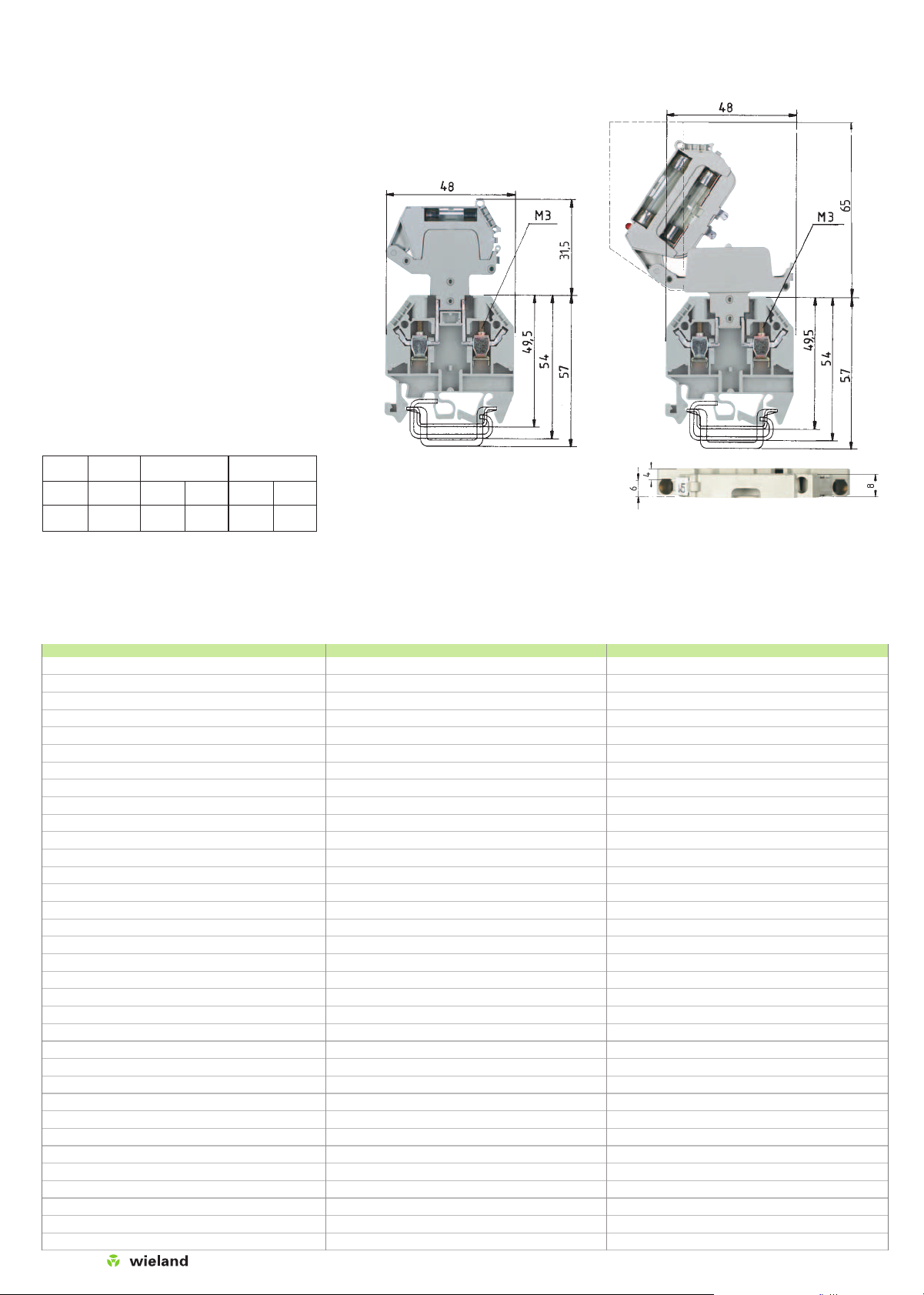
Disconnect blocks
with U-foot, type WK
WK 4 TKG/U 57.504.4055.0 100
THSI 6,3x32 Z1.298.1653.0 10
THSI 6,3x32 LED24 Z1.298.1753.0 10
THSI 6,3x32 LED60 Z1.298.1853.0 10
THSI 6,3x32 GL250 Z1.298.1953.0 10
35 x 27 x 7,5 EN 60715 98.300.0000.0 1
35 x 24 x 15 EN 60715 98.360.0000.0 1
9006 EN 60715 G-32 98.190.0000.0 1
WE 2/U Z5.523.5653.0 100
9708/2 S 35 Z5.522.8553.0 100
9708 Z5.522.7053.0 100
AP 4 TK 07.311.6155.0 10
TW 4 TK 07.311.8155.0 10
IVB 1 WK 4..-2 Z7.255.4227.0 10
IVB 1 WK 4..-6 Z7.255.4627.0 10
EN 60 947-7-1/DIN VDE 0611 Teil 1
EN 60 127-6/DIN VDE 0820 T6
UL ratings field/factory wiring
CSA ratings
Width Wire strip length
Approvals
WK 4 TKG...
mit THSi 5x20
fine-stranded solid V A
0.5 – 4 mm20.5 – 6 mm2800 V/8 kV/3
2) 1)
No. 22-10 AWG 300 V
2)
10
1)
No. 20-10 AWG 250 V
2)
6.3
1)
6 mm 9 mm
igtqw
WK 4 TKG...
mit THSi 6,3x32
fine-stranded solid V A
0.5 – 4 mm20.5–6 mm2800 V/8 kV/3
2) 1)
No. 22-10 AWG 300 V
2)
10
1)
No. 20-10 AWG 250 V
2)
6.3
1)
6 mm 9 mm
igtqw
WK 4 TKG/U 57.504.4055.0 100
THSI 5x20 Z1.298.1053.0 10
THSI 5x20 LED24 Z1.298.1153.0 10
THSI 5x20 LED60 Z1.298.1253.0 10
THSI 5x20 GL250 Z1.298.1353.0 10
35 x 27 x 7,5 EN 60715 98.300.0000.0 1
35 x 24 x 15 EN 60715 98.360.0000.0 1
9006 EN 60715 G-32 98.190.0000.0 1
WE 2/U Z5.523.5653.0 100
9708/2 S 35 Z5.522.8553.0 100
9708 Z5.522.7053.0 100
AP 4 TK 07.311.6155.0 10
TW 4 TK 07.311.8155.0 10
IVB 1 WK 4..-2 Z7.255.4227.0 10
IVB 1 WK 4..-6 Z7.255.4627.0 10
When selecting G fuse inserts, make sure that the specified
maximum power is not exceeded.
1)
The current is determined by the inserted fuse. 1)The
voltage range is determined by the built-in LED display.
2)
Depending on the application and the installation method,
the circumstances for increased temperature must be
checked in the closed fuse holders.
Higher ambient temperatures are an additional load for the
fuse inserts. Therefore, the reduction of the rated current
must be considered accordingly in these applications.
Indicator (24 V): Lamp color: red
Power consumption: 10.3 mA
Indicator (220 V): Lamp color: red
Current input: 0.3 mA
Type
Rated
Overload protection
Exclusive
voltage
short-circuit protection
Single Group Single Group
arrangement arrangement arrangement arrangement
THSI 5x20 250 V 1.6 W 1.6 W 4.0 W 2.5 W
THSI
6.3x32
500 V 2.5 W 1.6 W 4.0 W 4.0 W
1)
Maximum power loss at 23 °C ambient temperature
(according to DIN EN 60947-7-3)
Disconnect base block gray
Fuse disconnect lever
Fuse disconnect lever with LED 12–24 V
2)
Fuse disconnect lever with LED 24 – 60 V
2)
Fuse disconnect lever with GL 110–250 V
2)
Knife edge disconnect block gray
blue
– with 2 test bolts gray
Invertible plug disconnect block
m. Inver. plug w/o test bolt
C.: gray
– with test bolts left and right gray
Feed-through block gray
Accessories
1. Mounting rail TS 35, DIN rail, 7.5 mm high L = 2 m
Mounting rail TS 35, DIN rail 15 mm high L = 2 m
Mounting rail TS 32, G rail L = 2 m
2. End clamp with U-foot 10 mm wide
End clamp TS 35, with screw 8 mm wide
End clamp TS 32, with screw 7.5 mm wide
3. End plate, 1.5 mm thick gray
blue
4. Partition, 1.5 mm thick gray
blue
5. Jumper comb insulated 2 pole
to 6 pole
6. Cover f. cross conn. with marking facility
7. Snap-in partition plate with marking facility
For marking systems see pages 230-237
selos
159
Subject to change without further notice
Type Part No. Std. Pack Type Part No. Std. Pack Type Part No. Std. Pack
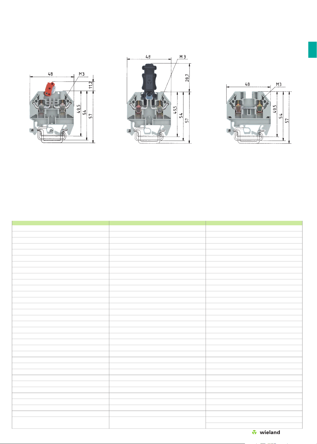
Disconnect blocks
with U-foot, type WK
WK 4/TKM
fine-stranded solid V A
0.5 – 4 mm20.5 – 6 mm2800 V/8 kV/3*)20
No. 22-10 AWG 600 V 20
No. 22-10 AWG 600 V*
)
20
6 mm 9 mm
igtqwd
WK 4 TKG-TRST/U
fine-stranded solid V A
0.5 – 4 mm20.5 – 6 mm2800 V/8 kV/3*)20
No. 22-10 AWG 300 V 10
No. 22-10 AWG 600 V*
)
20
6 mm 9 mm
igtqwd
WK 4 TKS D/U
fine-stranded solid V A
0.5 – 4 mm20.5 – 6 mm2800 V/8 kV/3 32
No. 22-10 AWG 300 V 25
No. 20-10 AWG 600 V 20
6 mm 9 mm
igtqw
WK 4/TKM/U 57.504.2055.0 100
WK 4/TKM/U BLAU 57.504.2055.6 100
WK 4/TKM/P3/U 57.504.2355.0 100
35 x 27 x 7,5 EN 60715 98.300.0000.0 1
35 x 24 x 15 EN 60715 98.360.0000.0 1
9006 EN 60715 G-32 98.190.0000.0 1
WE 2/U Z5.523.5653.0 100
9708/2 S 35 Z5.522.8553.0 100
9708 Z5.522.7053.0 100
AP 4 TK 07.311.6155.0 10
AP 4 TK BLAU 07.311.6155.6 10
TW 4 TK 07.311.8155.0 10
TW 4 TK BLAU 07.311.8155.6
10
IVB 1 WK 4..-2 Z7.255.4227.0 10
IVB 1 WK 4..-6 Z7.255.4627.0 10
*)Version with test bolt: CSA: 300 V
EN 60 947-7-1/DIN VDE 0611 T1 – 690 V/6 kV/3
Test bolt can be loaded with 1 A
The disconnecting knife in these WK versions swings in and out
on a pivot point. The distinctive color of the disconnecting lever
signals the open state. The terminals can be connected with
the lever open or closed. Designs with a different number and
arrangement of test sockets permit safe measurements using
the test plug.
The plug in disconnect terminal has the same profile as the
modular terminal WK4. The isolating connector is detachable
and can be fitted as a dummy plug. This signals the open state.
Designs with different numbers of test sockets permit safe
measurements using the test plug.
WK 4 TKG-TRST/U 57.504.4555.0 100
WK 4 TKG-TRST P3/U 57.504.4855.0 100
35 x 27 x 7,5 EN 60715 98.300.0000.0 1
35 x 24 x 15 EN 60715 98.360.0000.0 1
9006 EN 60715 G-32 98.190.0000.0 1
WE 2/U Z5.523.5653.0 100
9708/2 S 35 Z5.522.8553.0 100
9708 Z5.522.7053.0 100
AP 4 TK 07.311.6155.0 10
TW 4 TK 07.311.8155.0 10
IVB 1 WK 4..-2 Z7.255.4227.0 10
IVB 1 WK 4..-6 Z7.255.4627.0 10
*)Version with test bolt: CSA: 300 V
EN 60 947-7-1/DIN VDE 0611 T1 – 690 V/6 kV/3
Test bolt can be loaded with 1 A
WK 4 TKS D/U 57.504.4455.0 100
35 x 27 x 7,5 EN 60715 98.300.0000.0 1
35 x 24 x 15 EN 60715 98.360.0000.0 1
9006 EN 60715 G-32 98.190.0000.0 1
WE 2/U Z5.523.5653.0 100
9708/2 S 35 Z5.522.8553.0 100
9708 Z5.522.7053.0 100
AP 4 TK 07.311.6155.0 10
TW 4 TK 07.311.8155.0 10
IVB 1 WK 4..-2 Z7.255.4227.0 10
IVB 1 WK 4..-6 Z7.255.4627.0 10
AD VB 4 GELB 04.326.2153.8 10
TS 4 GELB 07.311.2153.8 10
Same dimensions as types WK 4 TKG/U
and WK 4/TKM/U
 Loading...