

Page 1
SNZ 4052K
TWO-HAND RELAY TYPE IIIC
] Y t
APPLICATIONS
• Protection of people and machinery
• Monitoring of two-hand applications
• Press
• According to EN 574 Type IIIC
• Up to PL e / Category 4 (EN ISO 13849-1)
• Up to SIL
3 (EN 62061)
CL
FEATURES
• Stop Category 0 according to EN 60204-1
• Two-channel actuation; 1 NO contact and
1 NC contact for each channel
• Cross monitoring
• Monitoring of synchronous activation
• 2 enabling current paths, 1 signaling current path
FUNCTION
The device complies with EN 574 Type III C safety requirements.
The safety behavior of the device is designed for applications
according to Category 4 (EN 954-1). The device is single-fault safe
and self-monitoring. Synchronous activation of both actuators
(two-hand momentary contact or safety gate contacts) is
monitored. Each of the two actuators is connected to the device
with an NO contact and an NC contact. The technical design of the
input circuit provides cross connection and ground fault
monitoring. The output function is designed with 2 NO contacts as
an enabling current path and 1 NC contact as signaling current
path (all forcibly guided).
With supply voltage applied to terminals A1/A2 and the feedback
loop (terminals Y1/Y2) closed, the enabling current paths are
closed by simultaneously activating the actuators (S1+S2).
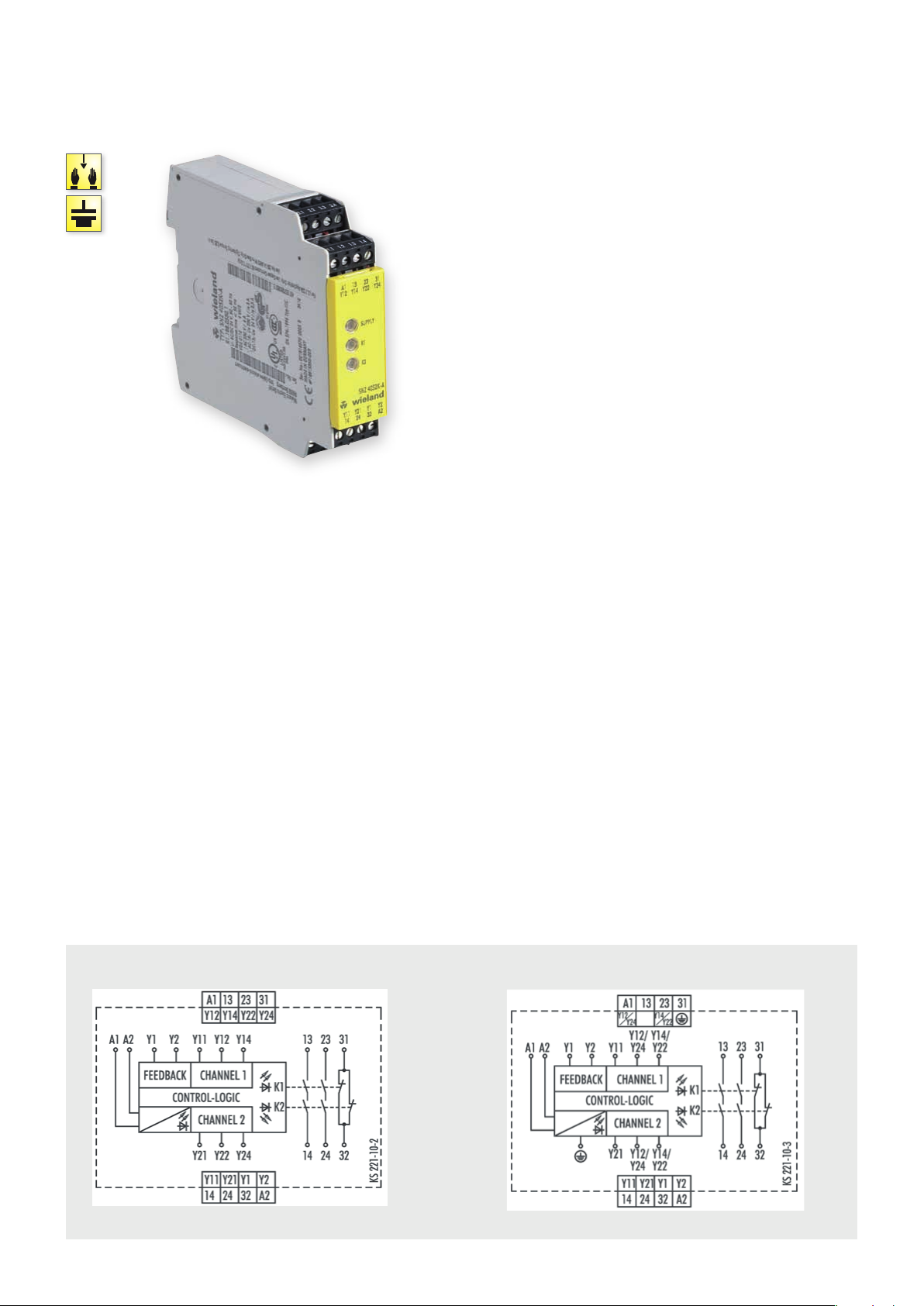
CIRCUIT DIAGRAM
SNZ 4052K
24 V DC 115-120 V AC / 230 V AC
Both actuators must be activated within 0.5 s for the output
contacts to be enabled. If only one of the two actuators is released,
the device is immediately de-energized. The enabling current paths
open.
The device can be restarted only after both actuators have
returned to their initial position (for example when the two-hand
momentary contact switches have been released) and the
feedback circuit is closed again. The feedback circuit should only
be opened again after both actuators are activated. Otherwise the
device will remain in the OFF position. The current status of the
device is indicated by 3 LEDs: application of the supply voltage with
LED SUPPLY, activation of both actuators with LED K1 and
additionally with LED K2 in case of synchronous activation.
.
58
safe RE LAY
Page 2

OVERVIEW OF DEVICES | PART NUMBERS
Typ e Rated voltage Ter minals Part no. P.U .
SNZ 4052K-A 24 V AC/DC R1.188.0530.1 1
115 – 120 V AC R1.188.0940.1 1
230 V AC R1.188.0950.1 1
SNZ 4052K-C 24 V AC/DC R1.188.2020.0 1
TECHNICAL DATA
Function Two-hand control relay
Function display 3 LEDs, green
Power supply circuit
Rated voltage U
N
A1, A2 24 V AC/DC, 115-120 V AC, 230 V AC
Rated consumption 24 V DC 2.4 W
115-120 V AC, 230 V AC 2.2 W / 3.1 VA
Rated frequency 50 - 60 Hz
Operating voltage range U
B
Electrical isolation supply circuit - control circuit yes (at UN = 115-230 V AC, 230 V AC)
Control circuit
Rated output voltage Y12/Y14, Y22/Y24, Y1 24 V DC
Input current / peak current Y11, Y21 60 mA / 1000 mA
Y2 < 100 mA
Response time t
Recover y time t
Release time t
Synchronous time t
/ t
A1
A2
W
R
S
Max. resistivity, per channel 24 V AC/DC ≤ (2.5 + (1.176 x U
115-120 V AC, 230 V AC ≤ (2.5 + (1.176 x U
Output circuit
Enabling paths 13/14, 23/24 normally open contact
Signaling paths 31/32 normally closed contact
Contact assignment forcebly guided
Contact type Ag-alloy, gold-plated
Rated switching voltage enabling / signaling path 230 V AC
Max. thermal current I
th
enabling / signaling path 6 A / 2 A
Max. total current I² of all current path (Tu = 55 ºC) 9 A²
Application category (NO) AC-15 U
DC-13 U
Short-circuit protection (NO), lead fuse / circuit breaker 6 A class gG / melting integral / < 100 A²s
Mechanical life 10
General data
Creepage distances and clearances bet ween the circuits EN 60 664 -1
Protection degree according to EN 60529 (housing / terminals) IP40 / IP20
Ambient temperature / storage temperature -25 ºC - +55 ºC / -25 ºC - + 75 ºC
Wire ranges screw terminals, fine-stranded / solid 1 x 0.2 mm² – 2.5 mm² / 2 x 0.2 mm² – 1.0 mm²
fine-stranded with ferrules 1 x 0.25 mm² – 2.5 mm² / 2 x 0.25 mm² – 1.0 mm²
Permissible torque 0.5 - 0.6 Nm
Wire ranges Push-in terminals 1 x 0.25 mm² – 1.5 mm²
Weight 0.20 kg / 0.25 kg
Standards EN ISO 13849-1, EN 62061, EN 574
Approvals TÜV, cULus, CCC
Screw terminals, pluggable
Screw terminals, pluggable
Screw terminals, pluggable
Push-in terminals, pluggable
0.85 - 1.1 x U
40 ms
250 ms
50 ms
≤ 500 ms
230 V, Ie 3 A
e
24 V, Ie 2.5 A
e
7
switching cycles
N
/ UN - 1) x 50) Ω
B
/ UN - 1) x 50) Ω
B
safe REL AY
safe RE LAY
.
59
 Loading...