

Wieland SNV 4274SL, SNV 4074ST Catalog Page
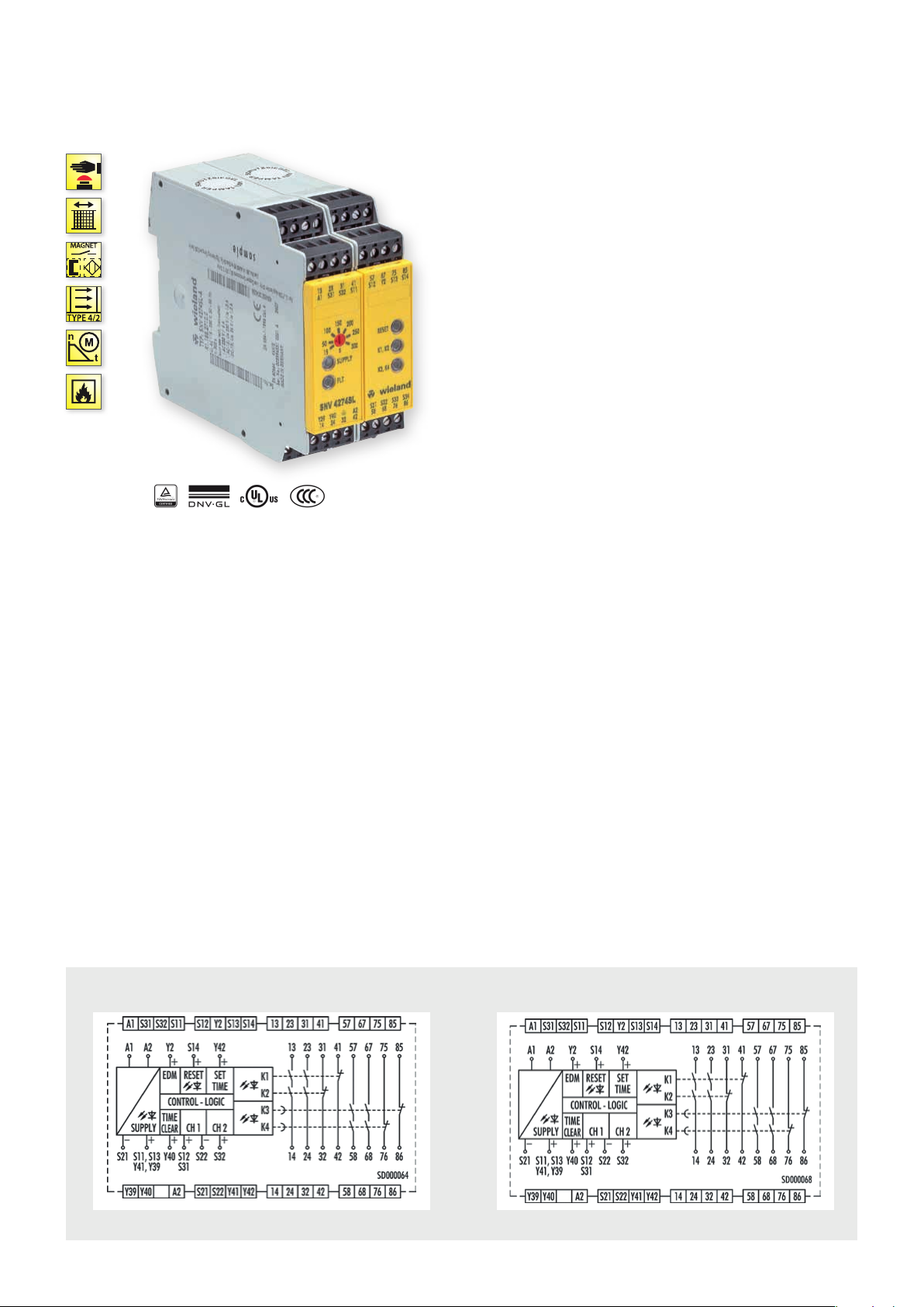
SNV 4274SL / SNV 4074ST – MONITORING OF EMERGENCY STOP,
LIGHT BARRIERS AND SAFETY GATES, OFF-DELAYED/ON-DELAYED
APPLICATIONS
• Monitoring of limit values in the process industry
• Monitoring of emergency stop applications
• Monitoring of safety gates
• Monitoring of interlocks
• Monitoring of light barriers
• Up to PL e / Categor y 4 (EN ISO 13849-1)
• Up to SIL
FEATURES
• Continuously adjustable, analog time setting
• Time ranges 3s, 30s or 300s
• Retriggering of the time delay possible
• Single-channel or two-channel control
• Manual or automatic start
• SafeStart
• Cross monitoring
] L Y t
3 (EN 62061)
CL
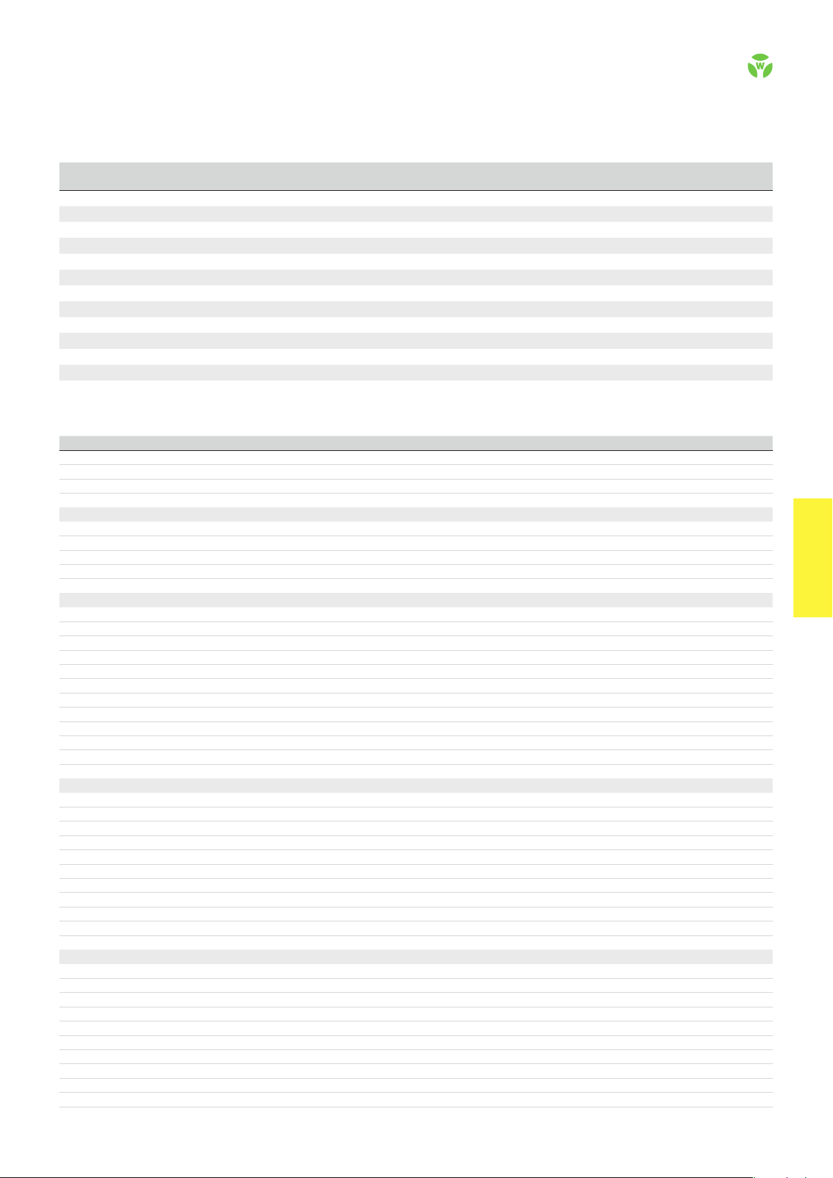
OFF-DELAY WITH RETRIGGERING FUNCTION (SNV 4274SL)
After the supply voltage is applied to terminals A1/A2 and the
safety inputs are closed, the contacts are switched on immediately,
either automatically or by pressing the reset button (manual start).
When the safety inputs are opened/de-energized, the contacts are
switched off immediately or with a release delay.
The set release delay only expires if the safety inputs are opened
longer than the release delay set on the device. If the safety inputs
are closed again before the release delay has expired (retriggering),
the delayed contacts will remain closed, too.
ON-DELAY FUNCTION (SNV 4074ST)
After the supply voltage is applied to terminals A1/A2 and the
safety inputs are closed, the contacts are switched on immediately
or with a response delay, either automatically or by pressing the
reset button (manual start). When the safety inputs are opened/
de-energized the contacts are switched off immediately.
CIRCUIT DIAGRAMS
SNV 4274SL SNV 4074ST
.
68
safe RE LAY
OVERVIEW OF DEVICES | PART NUMBERS
Typ e
SNV 4274SL-A 3s 24 V DC 115 – 230 V AC R1.188.2470.0 R1.188.2650.0 1
SNV 4274SL-A 30s 24 V DC 115 – 230 V AC R1.188.2500.0 R1.188.2680.0 1
SNV 4274SL-A 300s 24 V DC 115 – 230 V AC R1.188.2530.0 R1.188.2710.0 1
SNV 4274SL-C 3s 24 V DC 115 – 230 V AC R1.188.2480.0 R1.188.2660.0 1
SNV 4274SL-C 30s 24 V DC 115 – 230 V AC R1.188.2510.0 R1.188.2690.0 1
SNV 4274SL-C 300s 24 V DC 115 – 230 V AC R1.188.2540.0 R1.188.2720.0 1
SNV 4074ST-A 3s 24 V DC 115 – 230 V AC R1.188.2560.0 R1.188.2740.0 1
SNV 4074ST-A 30s 24 V DC 115 – 230 V AC R1.188.2590.0 R1.188.2770.0 1
SNV 4074ST-A 300s 24 V DC 115 – 230 V AC R1.188.2620.0 R1.188.2800.0 1
SNV 4074ST-C 3s 24 V DC 115 – 230 V AC R1.188.2570.0 R1.188.2750.0 1
SNV 4074ST-C 30s 24 V DC 115 – 230 V AC R1.188.2600.0 R1.188.2780.0 1
SNV 4074ST-C 300s 24 V DC 115 – 230 V AC R1.188.2630.0 R1.188.2810.0 1
Time
range
Rated voltage Ter min als
Screw terminals, pluggable
Screw terminals, pluggable
Screw terminals, pluggable
Push-in terminals, pluggable
Push-in terminals, pluggable
Push-in terminals, pluggable
Screw terminals, pluggable
Screw terminals, pluggable
Screw terminals, pluggable
Push-in terminals, pluggable
Push-in terminals, pluggable
Push-in terminals, pluggable
Part no. Part no.
24 V DC 115 – 230 V AC
P.U .
TECHNICAL DATA
Function Emergency stop relay
Function display 5 LEDs, green/red
Function mode / adjustment Time / stepless
Adjustment range 0.15 - 3 s / 1.5 - 30 s / 15 - 300 s
Power supply circuit
Rated voltage U
N
A1, A2 24 V DC / 115-230 V AC
Rated consumption 24 V DC | 115-230 V AC 2.8 W | 3.2 W / 6.3 VA
Rated frequency 50 - 60 Hz
Operating voltage range U
B
0.85 - 1.1 x U
N
Electrical isolation supply circuit - control circuit yes (at UN = 115-230 V AC)
Control circuit
Rated output voltage S11, S13, S33, Y39 / S21 22 V DC
Input current / peak current S12, S31/S22, S32 3 mA / 4,5 mA
S14, S34, Y2, Y40 4 mA / 4,5 mA
Response time t
Minimum ON time t
Recover y time t
Release time t
Release time t
/ t
A1
A2
100 ms
M
W
R
, delayed contacts (tolerance) 0,15 - 3 s (± 16 % of the set ting value)
R
200 ms
50 ms
20 ms
1,5 - 30 s (± 16 % of the setting value)
15 - 300 s (± 16 % of the setting value)
Permissable test pulse time t
Max. resistivity, per channel
TP
1)
24 V DC | 115-230 V AC < 50 Ω | < 50 Ω
< 1 ms
Output circuit
Enabling paths 13/14, 23/24 normally open contact
57/ 58 , 57/ 68 normally open contact, time delayed
Signaling paths 31/32, 41/42 | 75/76, 85/86 normally closed contact | normally closed contact, time delayed
Contact assignment forcebly guided
Contact type Ag-alloy, gold-plated
Rated switching voltage enabling- / signaling path 230 V AC
Max. thermal current I
Max. total current I
th
2
of all current path (Tu = 55 ºC) 40 A²
Application category (NO) AC-15 | DC-13 U
enabling- / signaling path 6 A / 2 A
230 V, Ie 3 A | Ue 24 V, Ie 3 A
e
Short-circuit protection (NO), lead fuse / circuit breaker 6 A class gG / melting integral < 100 A²s
Mechanical life 107 switching cycles
General data
Creepage distances and clearances between the circuits EN 60 664 -1
Protection degree according to EN 60529 (housing / terminals) IP40 / IP20
Ambient temperature / storage temperature -25 ºC - +55 ºC / -25 ºC - + 75 ºC
Wire ranges screw terminals, fine-stranded / solid 1 x 0.2 mm² – 2.5 mm² / 2 x 0.2 mm² – 1.0 mm²
fine-stranded with ferrules 1 x 0.25 mm² – 2.5 mm² / 2 x 0.25 mm² – 1.0 mm²
Permissible torque 0.5 - 0.6 Nm
Wire ranges push-in terminals 1 x 0.25 mm² – 1.5 mm²
Weight 0,33 kg / 0, 35 kg
Standards EN ISO 13849-1, EN 62061, EN 50156-1
Approvals TÜV, GL, cULus, CCC
1)
If two-channel devices are installed as single channel, the value is halved.
safe RE LAY
safe REL AY
.
69
 Loading...