

Wieland SNV 4074SL, SNV 4076SL Catalog Page
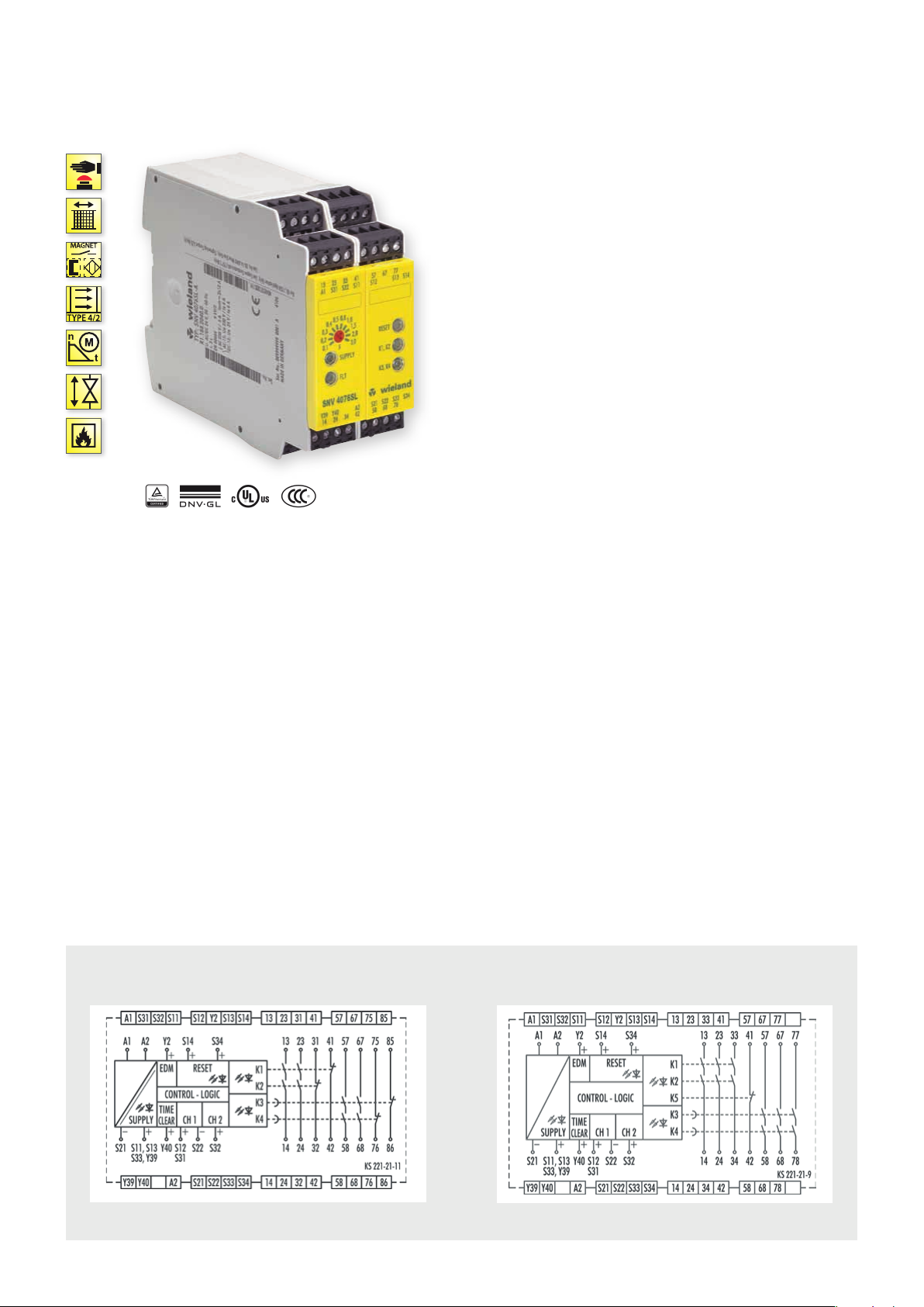
SNV 4074SL / SNV 4076SL
MONITORING OF EMERGENCY STOP, SAFETY GATES AND LIGHT BARRIERS, OFF-DELAYED
APPLICATIONS
• Controlled stop according to Categor y 1 (EN 60204-1)
• Monitoring of emergency stop applications
• Monitoring of safety gates
• Monitoring of interlocks
• Monitoring of light barriers
• Up to PL e / Category 4 (EN ISO 13849-1)
• Up to SIL
FEATURES
• Stop Category 0/1 according to EN 60204-1
• Time setting in 10 steps
• Time ranges 3s, 30s or 300s
• Single-channel or two-channel control
• Manual or automatic start
• SafeStart
• Cross monitoring
] L Y t
3 (EN 62061)
CL
OFF-DELAY FUNCTION
After the supply voltage is applied to terminals A1/A2 and the
safety inputs are closed, the enabling current paths (NO contacts)
are closed automatically or by pressing the reset button (manual
start). When the safety inputs are opened/de-energized the
enabling current paths (NO contacts are opened immediately or
with a delay).
• Automatic start – Reset input S14 is connected to safety input
S12. To monitor external contact blocks (EDM), their NC contacts
must be connected in series between S34 and S12.
• Manual start without monitoring – Reset input S14 is connected to safety input S12 via a reset button. To monitor external
contact blocks (EDM), their NC contacts must be connected in
series to the reset button.
• Manual start with monitoring – Reset input S34 is connected to
safety input S11 via a reset button. To monitor external contact
blocks (EDM), their NC contacts must be connected in series to
the reset button.
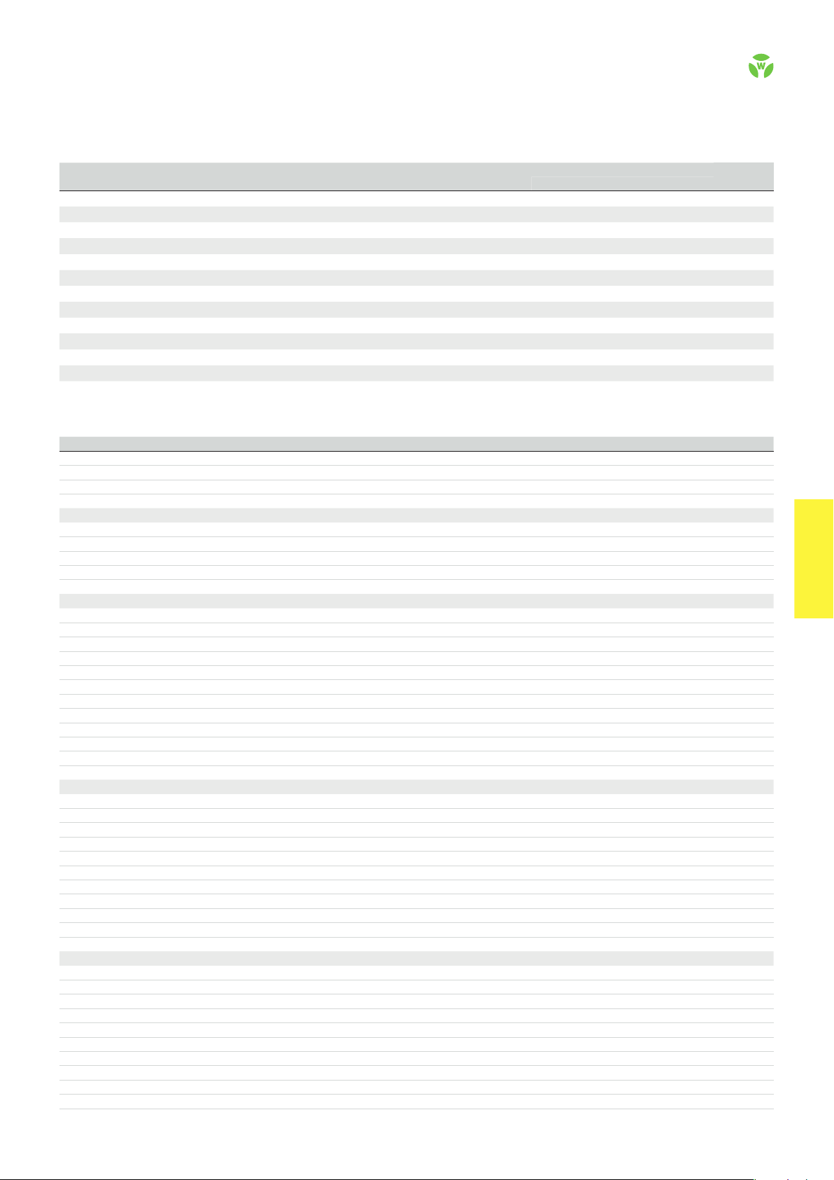
CIRCUIT DIAGRAMS
SNV 4074SL SNV 4076SL
.
66
safe RE LAY
OVERVIEW OF DEVICES | PART NUMBERS
Typ e
SNV 4074SL-A 3s 24 V DC 115 – 230 V AC R1.188.2130.0 R1.188.2310.0 1
SNV 4074SL-A 30s 24 V DC 115 – 230 V AC R1.188.2160.0 R1.188.2340.0 1
SNV 4074SL-A 300s 24 V DC 115 – 230 V AC R1.188.2190.0 R1.188.2370.0 1
SNV 4074SL-C 3s 24 V DC 115 – 230 V AC R1.188.2140.0 R1.188.2320.0 1
SNV 4074SL-C 30s 24 V DC 115 – 230 V AC R1.188.2170.0 R1.188.2350.0 1
SNV 4074SL-C 300s 24 V DC 115 – 230 V AC R1.188.2200.0 R1.188.2380.0 1
SNV 4076SL-A 3s 24 V DC 115 – 230 V AC R1.188.2040.0 R1.188.2220.0 1
SNV 4076SL-A 30s 24 V DC 115 – 230 V AC R1.188.2070.0 R1.188.2250.0 1
SNV 4076SL-A 300s 24 V DC 115 – 230 V AC R1.188.2100.0 R1.188.2280.0 1
SNV 4076SL-C 3s 24 V DC 115 – 230 V AC R1.188.2050.0 R1.188.2230.0 1
SNV 4076SL-C 30s 24 V DC 115 – 230 V AC R1.188.2080.0 R1.188.2260.0 1
SNV 4076SL-C 300s 24 V DC 115 – 230 V AC R1.188.2110.0 R1.188.2290.0 1
Time
range
Rated voltage Ter minals
Screw terminals, pluggable
Screw terminals, pluggable
Screw terminals, pluggable
Push-in terminals, pluggable
Push-in terminals, pluggable
Push-in terminals, pluggable
Screw terminals, pluggable
Screw terminals, pluggable
Screw terminals, pluggable
Push-in terminals, pluggable
Push-in terminals, pluggable
Push-in terminals, pluggable
Part no. Part no.
24 V DC 115 – 230 V AC
P.U .
TECHNICAL DATA
Function Emergency stop relay
Function display 5 LEDs, green/red
Function mode / adjustment Time setting in 10 steps
Adjustment range 0.1 - 3 s / 0 - 30 s / 0 - 300 s
Power supply circuit
Rated voltage U
N
A1, A2 24 V DC / 115-230 V AC
Rated consumption 24 V DC | 115-230 V AC 2.8 W | 3.2 W / 6,3 VA
Rated frequency 50 - 60 Hz
Operating voltage range U
B
0.85 - 1.1 x U
N
Electrical isolation supply circuit - control circuit yes (at UN = AC 115-230 V)
Control circuit
Rated output voltage S11, S13, S33, Y39 / S21 22 V DC
Input current / peak current S12, S31/S22, S32 3 mA / 4.5 mA
S14, S34, Y2, Y40 4 mA / 4.5 mA
Response time t
Minimum ON time t
Recover y time t
Release time t
Release time t
/ t
A1
A2
M
W
R
R
, delayed contacts (tolerance) 0.1 / 0.2 / 0.3 / 0.4 / 0,5 / 0.8 / 1 / 1.5 / 2 / 3 s (0,1 % ± 15 ms)
200 ms
100 ms
50 ms
20 ms
0 / 2 / 4 / 6 / 0.5 / 8 / 10 / 15 / 20 / 30 s (0.1 % ± 15 ms)
0 / 20 / 40 / 60 / 80 / 100 / 150 / 200 / 250 / 300 s (0.1 % ± 15 ms)
Permissable test pulse time t
Max. resistivity, per channel
TP
1)
24 V DC | 115-230 V AC < 50 Ω | < 50 Ω
< 1 ms
Output circuit
Enabling paths 13/14, 23/24, 33/34 normally open contact
57/ 58 , 57/ 68, 77/78 normally open contact, OFF-delayed
Signaling paths 31/32, 41/42 | 75/76, 85/86 normally closed contact | normally closed contact, OFF-delayed
Contact assignment forcebly guided
Contact type Ag-alloy, gold-plated
Rated switching voltage enabling- / signaling path 230 V AC
Max. thermal current I
Max. total current I
th
2
of all current path (Tu = 55 ºC) 40 A²
Application category (NO) AC-15 | DC-13 U
enabling- / signaling path 6 A / 2 A
230 V, Ie 3 A | Ue 24 V, Ie 3 A
e
Short-circuit protection (NO), lead fuse / circuit breaker 6 A class gG / melting integral < 100 A²s
Mechanical life 107 switching cycles
General data
Creepage distances and clearances between the circuits EN 606 64-1
Protection degree according to EN 60529 (housing / terminals) IP40 / IP20
Ambient temperature / storage temperature -25 ºC - +55 ºC / -25 ºC - +75 ºC
Wire ranges screw terminals, fine-stranded / solid 1 x 0.2 mm² – 2.5 mm² / 2 x 0.2 mm² – 1.0 mm²
fine-stranded with ferrules 1 x 0.25 mm² – 2.5 mm² / 2 x 0.25 mm² – 1.0 mm²
Permissible torque 0.5 - 0.6 Nm
Wire ranges push-in terminals 1 x 0.25 mm² – 1.5 mm²
Weight 0.33 kg / 0.35 kg
Standards EN ISO 13849-1, EN 62061, EN 50156-1
Approvals TÜV, GL, cULus, CCC
1)
If two-channel devices are installed as single channel, the value is halved.
safe RE LAY
safe RELAY
.
67
 Loading...