

Wieland SNV 4063KL Catalog Page
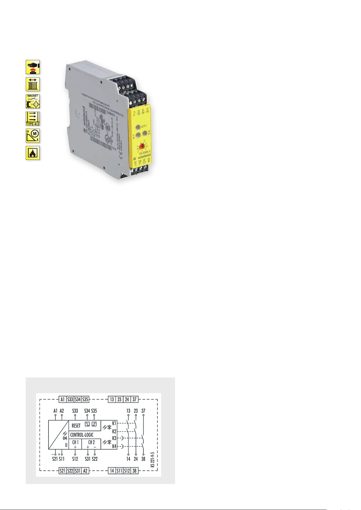
SNV 4063KL
MONITORING OF EMERGENCY STOP, SAFETY GATES AND LIGHT BARRIERS, OFF-DELAYED
APPLICATIONS
• Protection of people and machinery
• Monitoring of emergency stop applications
• Monitoring of safety gates
• Monitoring of light barriers
• Termination of braking operations through OFF-delay time
• Control of solenoid-actuated interlocks
• Up to PL e / Category 4 (EN ISO 13849-1) for undelayed contacts
• Up to PL d / Category 3 (EN ISO 13849-1) for delayed contacts
• Up to SILCL 3 (EN 62061)
FEATURES
• Stop category 0/1 according to EN 60204-1
• Single-channel or two-channel control
• Manual or automatic start
•
OFF-delay time adjustable in the range 0.15 to 3 s or 1.5 to 30 s
• Reset button monitoring, cross monitoring,
monitoring of synchronous time
] L Y t
• 3 enabling current paths (2 undelayed, 1 OFF-delayed)
FUNCTION
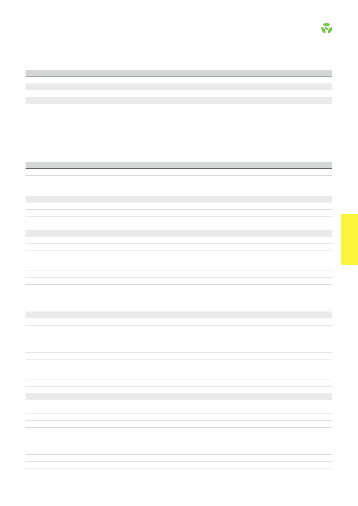
With the supply voltage applied to terminals A1/A2 and the
emergency set right and left margins in-line button. This controls
relays K1 to K4, which become self-locking (when starting via reset
button monitoring after the response time). After this switch-on
phase the 3 enabling current paths are closed (terminals 13/14,
23/24 and 37/38). Three LEDs display the state of relays K1/K2, K3/
K4 and the supply voltage.
If the emergency stop button is activated, the current supplies for
relays K1 to K4 are interrupted. The undelayed enabling current
paths (terminals 13/14, 23/24) are opened with release time tR1
while the off-delayed enabling current path (terminals 37/38) is
opened after the pre-set OFF-delay time tR2. The OFF-delay time
can be adjusted infinitely in the range 0.15 to 3 s or 1.5 to 30 s.
CIRCUIT DIAGRAM
SNV 4063KL
With a two-channel control and cross-monitoring wiring of the
sensor circuit, additional errors such as short-circuit or ground fault
can be detected. An electronic fuse protects the device against
damage. After the cause of the malfunction has been removed, the
device is operational again after approx. 3 s.
• Reset button monitoring – The device can be started either with
the falling edge or with the rising edge (terminals S34 or S35). For
emergency stop applications with manual start the button must
be connected to terminals S33/S34. The device is enabled only
with the falling edge of the reset signal. For starting, the reset
button must be pressed and released. For safety gate applications in which an automatic start is performed it is necessary to
bridge terminals S33/S35. The device will react at the rising edge
of input S12 which is internally connected to S33.
• Monitoring of synchronous time – The use of safety limit
switches for single-channel or two-channel circuits in safety gate
applications depends on the required safety level. The device
provides a monitoring of the synchronous time of two connected
safety switches. A synchronous time t
switches positioned in such a way that channel 1, terminals S11/
S12, closes before channel 2, terminals S21/S22. If channel 2
closes before channel 1, the synchronous time is t
≈ 0.5 s requires limit
S
= ∞.
S
.
62
safe RE LAY
OVERVIEW OF DEVICES | PART NUMBERS
Typ e Time range Rated voltage Ter minals Part no. P.U .
SNV 4 06 3K L-A 3 s 24 V DC R1.188.0620.0 1
30 s 24 V DC R1.188.0640.0 1
150 s 24 V DC R1.188.4100.0 1
SNV 4 06 3K L-C 3 s 24 V DC R1.188.2010.0 1
30 s 24 V DC R1.188.3900.0 1
TECHNICAL DATA
Function Emergency stop relay for controlled stop
Function display 3 LEDs, green
Function mode / adjustment Time / stepless
Adjustment range 0.15 - 3 s / 1.5 - 30 s / 7.5 - 150 s
Power supply circuit
Rated voltage U
N
A1, A2 24 V DC
Rated consumption 24 V DC 2.6 W
Operating voltage range U
B
Electrical isolation supply circuit - control circuit no
Control circuit
Rated output voltage S11, S33/S21 22 V DC
Input current / peak current S12, S31/S22 25 mA / 100 mA
S34, S35 40 mA / 50 mA
Response time t
Minimum ON time t
Recover y time t
Release time t
Release time t
Synchronous time t
Permissable test pulse time t
Max. resistivity, per channel
/ t
A1
A2
200 ms
M
W
R
, delayed contacts (tolerance) 0.15 - 3 s / 1.5 - 30 s (±16 %)
R
S
TP
1)
Output circuit
Enabling paths 13/14, 23/24 normally open contact
37/ 38 normally open contact, OFF-delayed
Contact assignment forcebly guided
Contact type Ag-alloy, gold-plated
Rated switching voltage enabling path 230 V AC
Max. thermal current I
Max. total current I
2
of all current path (Tu = 55 ºC) 5 A²
th
enabling path 6 A
Application category (NO) AC-15 U
DC-13 U
Short-circuit protection (NO), lead fuse / circuit breaker 6 A Class gG / melting integral < 100 A²s
Mechanical life 10
General data
Creepage distances and clearances bet ween the circuits EN 60 664 -1
Protection degree according to EN 60529 (housing / terminals) IP40 / IP20
Ambient temperature / storage temperature -25 ºC - +55 ºC / -25 ºC - + 75 ºC
Wire ranges screw terminals, fine-stranded / solid 1 x 0.2 mm² – 2.5 mm² / 2 x 0.2 mm² – 1.0 mm²
fine-stranded with ferrules 1 x 0.25 mm² – 2.5 mm² / 2 x 0.25 mm² – 1.0 mm²
Permissible torque 0.5 - 0.6 Nm
Wire ranges push-in terminals 1 x 0.25 mm² – 1.5 mm²
Weight 0.20 kg
Standards EN ISO 13849-1, EN 62061, EN 50156-1
Approvals TÜV, GL, cULus, CCC
1)
If two-channel devices are installed as single channel, the value is halved.
Screw terminals, pluggable
Screw terminals, pluggable
Screw terminals, pluggable
Push-in terminals, pluggable
Push-in terminals, pluggable
0.85 - 1.1 x U
N
30 ms / 700 ms
500 ms
25 ms
500 ms
< 1 ms
≤ (5 + (1.176 x UB / UN - 1) x 100) Ω
230 V, Ie 3 A
e
24 V, Ie 2 A
e
7
switching cycles
safe REL AY
safe RE LAY
.
63
 Loading...