

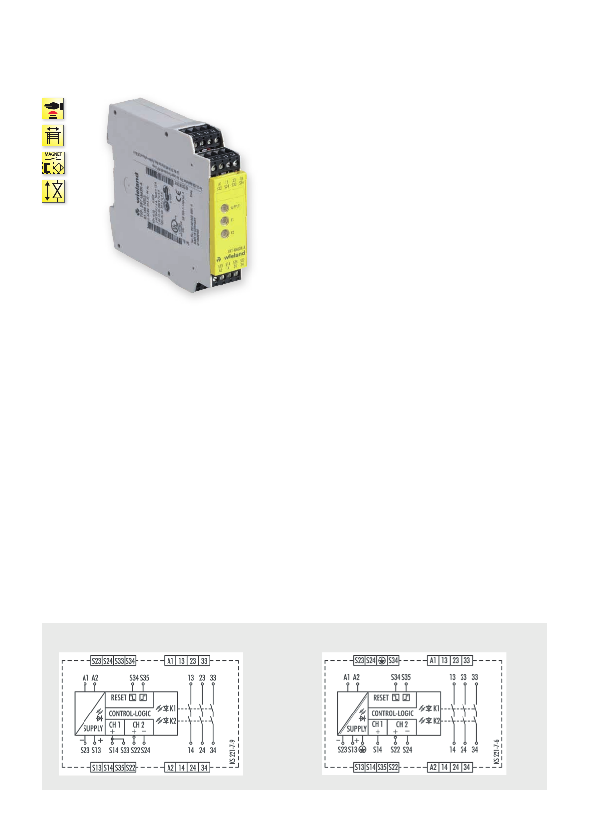
SNT 4M63K
MONITORING OF EMERGENCY STOP AND SAFETY GATES
APPLICATIONS
• Protection of people and machinery
• Monitoring of emergency stop applications
• Monitoring of safety gates
• Up to PL e / Category 4 (EN ISO 13849-1)
• Up to SIL
FEATURES
• Stop Category 0 according to EN 60204-1
• Manual or automatic start
• Cross monitoring
• 3 enabling current paths (NO contact, forcibly guided)
• Feedback loop for monitoring external contactors
@ Y t
3 (EN 62061)
CL
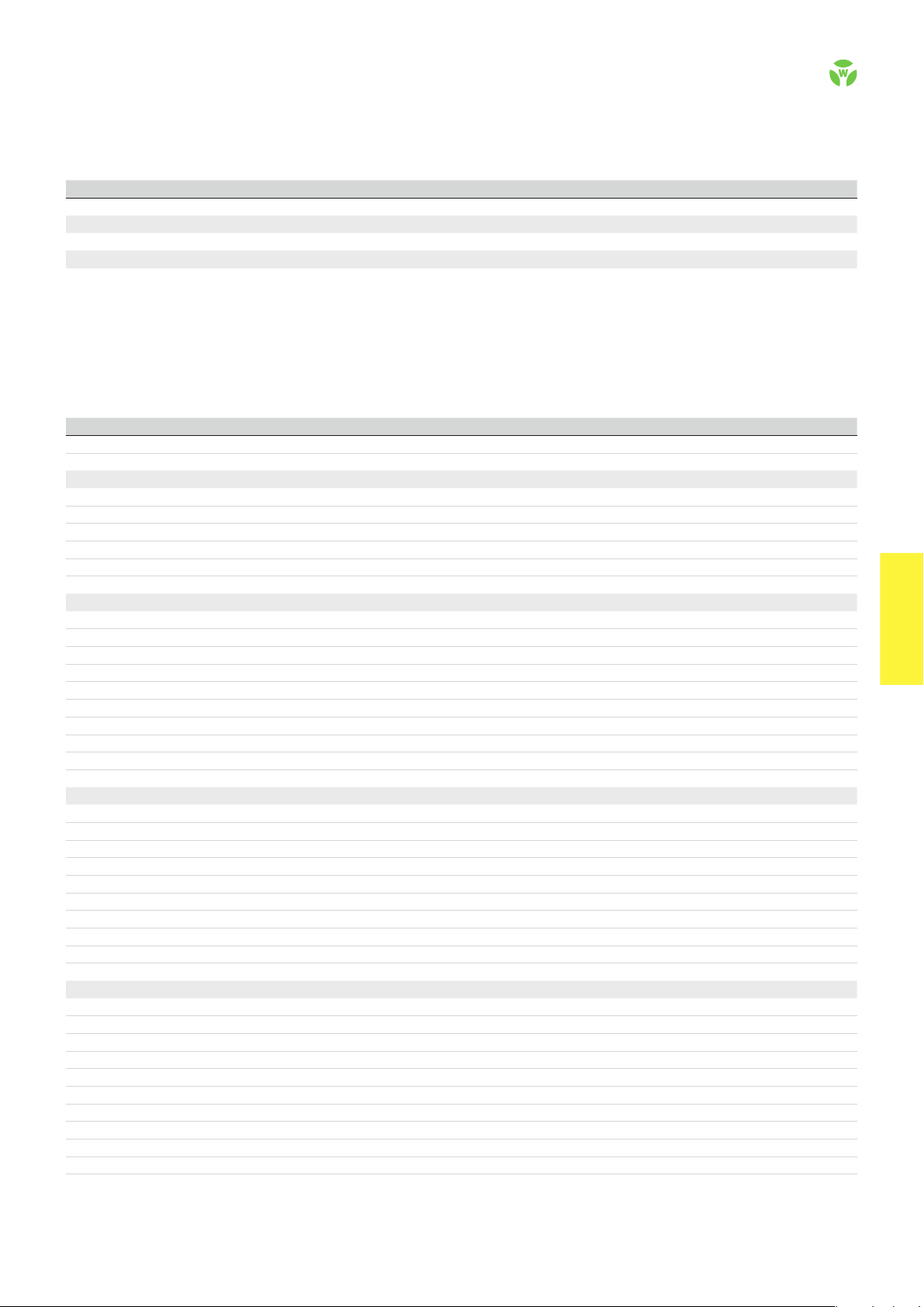
FUNCTION
The device is a two-channel switching device with self-monitoring
on each ON-OFF cycle. It complies with EN 60204-1 and is equipped
with forcibly guided relays. It is intended for monitoring connected
switching elements on separating safety devices and generating a
safety-oriented signal (enable). Depending on the design,
separating safety devices may include sliding safety gates, safety
gates, housings, covers, sheetings, screens, etc.
BASIC FUNCTION
With supply voltage applied to terminals A1/A2 and the safety
inputs closed, pressing the reset button closes the enabling current
paths (manual start). When the safety inputs are opened the
enabling paths will open.
• Manual start – When the safety inputs are closed, a button is
used to close reset input S34 and open it again (triggering with
falling edge) or to close reset input S35 (triggering with rising
edge).
• Automatic Start – Reset input S35 is connected to S33/S14. The
device starts with the rising edge of the signal on safety input S14.
CIRCUIT DIAGRAM
SNT 4M63K 24 V DC 115-120 V AC / 230 V AC
.
56
safe RE LAY
OVERVIEW OF DEVICES | PART NUMBERS
Typ e Rated voltage Ter minal s Part no. P.U .
SNT 4M63K-A 24 V AC/DC R1.188.1050.0 1
115 – 120 V AC R1.188.1060.0 1
230 V AC R1.188.1070.0 1
SNT 4M63K-C 24 V AC/DC R1.188.2390.0 1
TECHNICAL DATA
Function Emergency stop relay, valve position and safety gate monitoring
Function display 3 LEDs, green
Power supply circuit
Rated voltage U
N
A1, A2 24 V AC/DC, 115-120 V AC, 230 V AC
Rated consumption 24 V DC 2.0 W
115-120 V AC, 230 V AC 2,6 W / 3.2 VA
Rated frequency 50 - 60 Hz
Operating voltage range U
B
Electrical isolation supply circuit - control circuit yes (at UN = 115-230 V AC, 230 V AC)
Control circuit
Rated output voltage S13/S23 22 V DC
Input current / peak current S14/S33, S22/S24 40 mA / 100 mA
S34, S35 5 mA / 50 mA
Response time t
Minimum ON time t
Recover y time t
Release time t
Synchronous time t
Max. resistivit y, per channel
/ t
A1
A2
M
W
R
S
1)
24 V AC/DC ≤ (5 + (1.176 x UB / UN - 1) x 100) Ω
115-120 V AC, 230 V AC ≤ (5 + (1.176 x U
Output circuit
Enabling paths 13/14, 23/24, 33/34 normally open contact
Contact assignment forcebly guided
Contact type Ag-alloy, gold-plated
Rated switching voltage enabling path 230 V AC
Max. thermal current I
th
enabling path 6 A
Max. total current I² of all current path (Tu = 55 ºC) 9 A²
Application category (NO) AC-1 5 U
DC-13 U
Short-circuit protection (NO), lead fuse / circuit breaker 6 A class gG / melting integral < 100 A²s
Mechanical life 10
General data
Creepage distances and clearances between the circuits EN 6066 4-1
Protection degree according to EN 60529 (housing / terminals) IP40 / IP20
Ambient temperature / storage temperature -25 ºC - +55 ºC / -25 ºC - + 75 ºC
Wire ranges screw terminals, fine-stranded / solid 1 x 0.2 mm² – 2.5 mm² / 2 x 0.2 mm² – 1.0 mm²
fine-stranded with ferrules 1 x 0.25 mm² – 2.5 mm² / 2 x 0.25 mm² – 1.0 mm²
Permissible torque 0.5 - 0.6 Nm
Wire ranges push-in terminals 1 x 0.25 mm² – 1-5 mm²
Weight 0-21 kg / 0-25 kg
Standards EN ISO 13849-1, EN 62061
Approvals DGUV, cULus, CCC
1)
If two-channel devices are installed as single channel, the value is halved.
Screw terminals, pluggable
Screw terminals, pluggable
Screw terminals, pluggable
Push-in terminals, plug gable
0.85 - 1.1 x U
40 ms / 600 ms
80 ms
100 ms
15 ms
200 ms (CH1 → CH2)
230 V, Ie 3 A
e
24 V, Ie 2.5 A
e
7
switching cycles
N
/ UN - 1) x 100) Ω
B
safe REL AY
safe RE LAY
.
57
 Loading...