

Wieland SNS 4074K, SNS 4084K Catalog Page
SNS 4074K / SNS 4084K
STANDSTILL MONITOR
] Y
APPLICATIONS
• Standstill monitoring
• Monitoring of electrical lockout devices
• Control of spring-actuated tumblers
• Monitoring of low rotational speeds in setup operation
• Up to PL e / Category 4 (EN ISO 13849-1)
• Up to SIL
3 (EN 62061)
CL
FEATURES
• Reliable monitoring of dynamic input signals
• Adjustable monitoring frequency 0.1 – 99 Hz
• 4 selectable operating mode groups
• Single-channel or two-channel control
• Manual or automatic start
• Cross monitoring
• 4 safe semi-conductor outputs
STANDSTILL MONITORING FUNCTION
The SNS 4084K standstill monitor provides for the safe monitoring
of the frequency of a signal at inputs I1 to I4 of the device. If the
frequency of the impulses is higher than the frequency set at the
rotary switches (0.1 – 99 Hz), outputs Q1/Q2 will switch off. This
monitoring function can be used to detect the standstill or a lower,
safer rotational speed of a machine.
In applications of this sort, a spring-actuated or magnet-actuated
tumbler of an electric interlocking device, for example, can be
controlled from the output of the device.
The sensors for the detection of movement can, for example, be
two inductive proximity switches or a rotary encoder connected to
inputs I1 - I4. The frequency of the impulses to be monitored is set
at the two rotary switches and splitter input T1, and is stored in the
device on which the ENTER button is pressed while the voltage is
applied to the device.
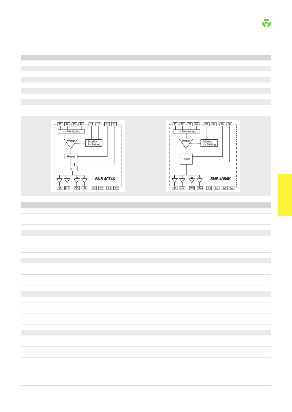
CIRCUIT DIAGRAM
SNS 4074K / SNS 4084K
SNS 4074K
The device features a bypass input, which allows safety-oriented
bypassing of the monitoring function, e.g. when a safe position has
been reached. In this case, the signal must fulfill at least the safety
category of the selected monitoring function.
SNS 4084K
The device features an input for the implementation of a start
override, which allows the safe outputs to be switched off even
during machine standstill. This means, for example, that a springactivated protective locking facility can be activated during
machine start-up.
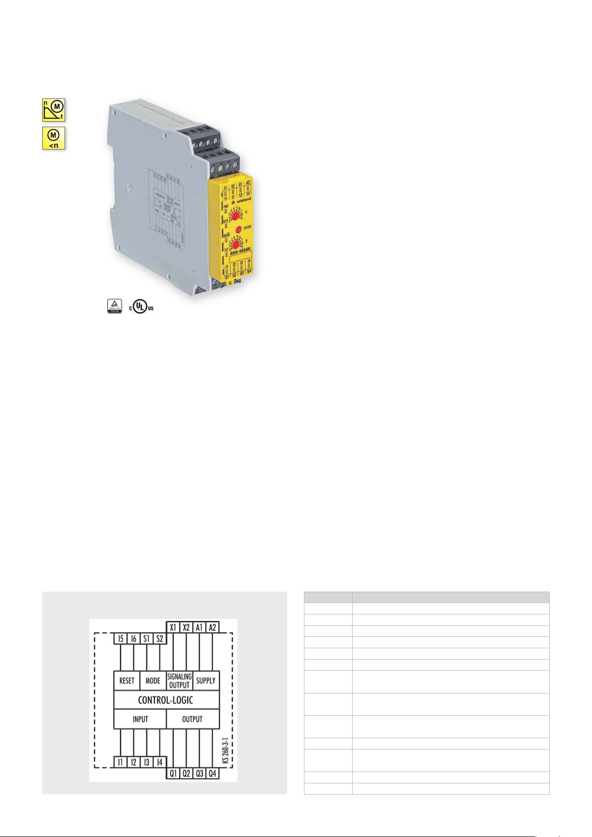
Ter m in a l s Description
A1 + 24 V
A2 GND
X1 / X2 Signal output, semi-conductor (plus switching)
S1 Configuration input for operating mode group
S2 Configuration input for operating mode group
I1 Sensor input
I2
I3
I4
I5 Reset input
I6
Q1 / Q2 Safe Output, semi-conductor (plus switching)
Q3 / Q4 Safe Output, semi-conductor (plus switching), inver ted
Sensor / configuration input
(depending on the operating mode group)
Sensor / configuration input
(depending on the operating mode group)
Sensor / configuration input
(depending on the operating mode group)
Bypass input (SNS 4074K) /
start override input (SNS 4084K)
.
52
safe RE LAY
OVERVIEW OF DEVICES | PART NUMBERS
Typ e Frequency range Ter minal s Part no. P.U .
SNS 4074K-A R1.188.3640.0 1
SNS 4074K-C R1.188.3650.0 1
SNS 4074K-A R1.188.3620.0 1
SNS 4074K-C R1.188.3630.0 1
SNS 4084K-A R1.188.3480.0 1
SNS 4084K-C R1.188.3490.0 1
SNS 4084K-A R1.188.3660.0 1
SNS 4084K-C R1.188.3670.0 1
0.5 - 99 Hz Screw terminals, pluggable
0.5 - 99 Hz Push-in terminals, pluggable
0.1 - 9.9 Hz Screw terminals, pluggable
0.1 - 9.9 Hz Push-in terminals, pluggable
0.5 - 99 Hz Screw terminals, pluggable
0.5 - 99 Hz Push-in terminals, pluggable
0.1 - 9.9 Hz Screw terminals, pluggable
0.1 - 9.9 Hz Push-in terminals, pluggable
FUNCTION DIAGRAM
TECHNICAL DATA
Function Standstill monitoring
Function display 12 LEDs, green/red
Function mode / adjustment Frequency monitoring / 2 x-position switch
Adjustment range f
ST
0,1 - 99 Hz / 0,5 - 99 Hz
Power supply circuit
Rated voltage U
N
A1, A2 24 V DC
Rated consumption 24 V DC 1.8 W
Operating voltage range U
B
0.85 - 1.1 x U
N
Electrical isolation supply circuit - control circuit no
Control circuit
Rated output voltage 24 V DC
Input current / peak current I1 - I6, S1, S2 3 mA / 3,8 mA
Minimum ON time t
Release time t
R
M
100 ms (< 5 s)
12 ms + 1.6 / f
ST
Max. cable length per input 100 m
Output circuit
Enabling paths Q1, Q2, Q3, Q4 Semi-conductor (plus switching), safety-related
Signaling paths X1, X2 Semi-conductor (plus switching), not safety-related
Rated switching voltage enabling path 30 V DC
Max. thermal current I
th
enabling path 2 A
Max. total current I² of all current path (Tu = 55 ºC) 4 A
Mechanical life Must be short-circuit proof
General data
Creepage distances and clearances between the circuits EN 60 664 -1
Protection degree according to EN 60529 (housing / terminals) IP40 / IP20
Ambient temperature / storage temperature -25 ºC - +55 ºC / -25 ºC - + 75 ºC
Wire ranges screw terminals, fine-stranded / solid 1 x 0.2 mm² – 2.5 mm² / 2 x 0.2 mm² – 1.0 mm²
fine-stranded with ferrules 1 x 0.25 mm² – 2.5 mm² / 2 x 0.25 mm² – 1.0 mm²
Permissible torque 0.5 - 0.6 Nm
Wire ranges push-in terminals 1 x 0.25 mm² – 1.5 mm²
Weight 0.16 kg
Standards EN ISO 13849-1, EN 62061
Approvals TÜV, cULus
safe REL AY
safe RE LAY
.
53
 Loading...