

SNO 4083KM
MONITORING OF EMERGENCY STOP, SAFETY GATES AND LIGHT BARRIERS
APPLICATIONS
• Protection of people and machinery
• Monitoring of emergency stop applications
• Monitoring of safety gates
• Monitoring of light barriers
• Up to PL e / Categorie 4 (EN ISO 13849-1)
• Up to SIL
FEATURES
• Stop Category 0 according to EN 60204-1
• Single-channel or two-channel control
• Two-channel control with NC/NC or NC/NO
• Manual or automatic start
• SafeStart
• Cross monitoring
• Synchronous time monitoring for two-channel control
• 3 enabling current path / 1 signalling current path
] Y t L
3 (EN 62061)
CL
FUNCTION
After the supply voltage is applied to terminals A1/A2 and the
safety inputs are closed, the enabling current paths (NO contacts)
are closed and the signal current path (NC contact) is opened
automatically or by pressing the reset button (manual monitored
start). When the safety inputs are opened/ de-energized the
enabling current paths (NO contacts) are opened immediately and
the signal current path (NC contact) is closed.
• Reduced installation work – The SNO 4083KM requires fewer
connection cables, irrespective of whether operation with or
without cross monitoring is desired. This saves time and money
when it comes to wiring.
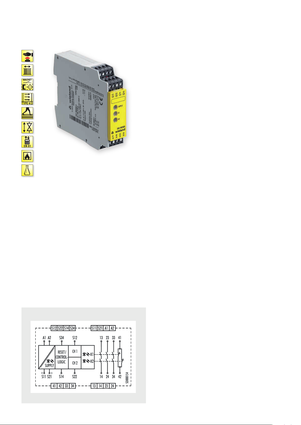
CIRCUIT DIAGRAM
SNO 4083KM
• Universal application – The two-channel control of the device is
carried out by either an NC/NC or an NC/NO combination of the
safety sensor.
In the case of two-channel control of the device, a synchronous
time is automatically monitored between the two channels.
• SafeStart function – When the device is used with a manual
start, the reset input is automatically monitored for a rising and
falling signal edge.
A manual reset signal is only accepted if the control inputs of the
device are activated by the safe transducer (e.g. emergency stop
button) during the entire activation procedure.
• Monoflop function – This function is integrated into the device
and prevents device interlocking under all circumstances. This is
a decisive advantage in applications where very short interruptions of the safety-related signals can occur, or in the case of
transducers with bouncing contacts or safe optical sensors
(BWS), for example.
• Simple diagnosis – The device features an intelligent display
system that shows the user the different operating modes of the
device in its different applications. This means, for example, that
when the control inputs are closed and manual start has been
selected, a reset signal is displayed, which has not yet been given.
Fault states in the control (e.g. synchronous time exceeded or a
short-circuit in two-channel control) are also signaled to the user
via a blinking code.
.
38
safe RE LAY

OVERVIEW OF DEVICES | PART NUMBERS
Typ e Rated voltage Synchr. Time Ter minal s Part no. P.U .
SNO 4083KM-A 24 V DC R1.188.3580.0 1
SNO 4083KM-A 115-230 V AC R1.188.3590.0 1
SNO 4083KM-C 24 V DC R1.188.3600.0 1
SNO 4083KM-C 115-230 V AC R1.188.3610.0 1
SNO 4083KM-A 24 V DC R1.188.3830.0 1
SNO 4083KM-A 115-230 V AC R1.188.3840.0 1
SNO 4083KM-C 24 V DC R1.188.3850.0 1
SNO 4083KM-C 115-230 V AC R1.188.3860.0 1
TECHNICAL DATA
Function Emergency stop relay
Function display 3 LEDs, green
Power supply circuit
Rated voltage U
N
Rated consumption 24 V DC 1.6 W
Rated frequency 50 - 60 Hz
Operating voltage range U
B
Electrical isolation supply circuit - control circuit yes (at UN = 115-230 V AC)
Control circuit
Rated output voltage S11/S21 22.5 V DC
Input current / peak current S12, S22 25 mA / 100 mA
Response time t
Minimum ON time t
Recover y time t
Release time t
Synchronous time t
Permissable test pulse time t
Max. resistivity, per channel
/ t
A1
A2
60 ms
M
W
R
S
TP
1)
Output circuit
Enabling paths 13/14, 23/24, 33/34 normally open contact
Signaling paths 41/42 normally closed contact
Contact assignment forcebly guided
Contact type Ag-alloy, gold-plated
Rated switching voltage enabling / signaling path 230 V AC
Max. thermal current I
th
Max. total current I² of all current path (Tu = 55 ºC) / (Tu = 65 ºC) 25 A² / 9 A²
Application category (NO) AC-15 U
Short-circuit protection (NO), lead fuse / circuit breaker 6 A class gG / melting integral < 100 A²s
Mechanical life 10
General data
Creepage distances and clearances between the circuits EN 60 664 -1
Protection degree according to EN 60529 (housing / terminals) IP40 / IP20
Ambient temperature / storage temperature -25 ºC - +65 º C / -25 ºC - + 75 ºC
Wire ranges screw terminals, fine-stranded / solid 1 x 0.2 mm² – 2.5 mm² / 2 x 0.2 mm² – 1.0 mm²
Permissible torque 0.5 - 0.6 Nm
Wire ranges push-in terminals 1 x 0,25 mm² – 1.5 mm²
Weight 24 V AC/DC device / AC device 0.2 kg
Standards EN ISO 13849-1, EN 62061, EN 81-20/50, EN 50156-1, EN 61511
Approvals TÜV, cULus, CCC, GL
1)
If two-channel devices are installed as single channel, the value is halved.
1.5 s Screw terminals, pluggable
1.5 s Screw terminals, pluggable
1.5 s Push-in terminals, pluggable
1.5 s Push-in terminals, pluggable
0.5 s Screw terminals, pluggable
0.5 s Screw terminals, pluggable
0.5 s Push-in terminals, pluggable
0.5 s Push-in terminals, pluggable
A1, A2 24 V DC/ 115-230 V AC
115-230 V AC 1.8 W / 4.0 VA
0.85 - 1.1 x U
N
S14, S3 4 3 mA / 5 mA
250 ms
120 ms
< 35 ms
0.5 s / 1.5 s
< 0,8 ms
24 V DC ≤ (5 + (1.176 x UB / UN - 1) x 100) Ω
115-230 V AC ≤ 12 Ω
enabling / signaling path 6 A / 2 A
230V, Ie 5 A
e
DC-13 U
24V, Ie 5A
e
7
switching cycles
fine-stranded with ferrules 1 x 0.25 mm² – 2.5 mm² / 2 x 0.25 mm² – 1.0 mm²
safe REL AY
safe RE LAY
.
39
 Loading...