

Page 1
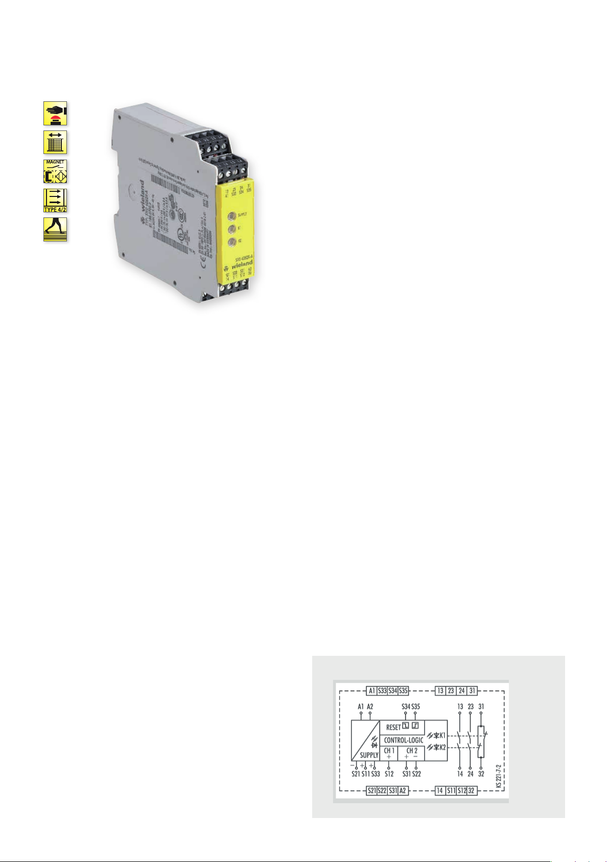
SNO 4062K/KM
MONITORING OF EMERGENCY STOP, SAFETY GATES AND LIGHT BARRIERS
APPLICATIONS
• Protection of people and machinery
• Monitoring of emergency stop applications
• Monitoring of safety gates
• Monitoring of light barriers
• Up to PL e / Category 4 (EN ISO 13849-1)
• Up to SIL
FEATURES
• Stop Category 0 according to EN 60204-1
• Reset button monitoring
• Manual or automatic start
Single-channel or two-channel control
• Cross monitoring
• 2 enabling current paths, 1 signal current path
@ Y t
3 (EN 62061)
CL
FUNCTION
SNO 4062K
The device is a two-channel switching device for emergency stop
applications with self-monitoring on each ON-OFF cycle. It
complies with EN 60204-1 and is equipped with forcibly guided
relays.
BASIC FUNCTION:
With supply voltage applied to terminals A1/A2 and the safety
inputs closed, pressing the reset button closes the enabling current
paths (manual start). When the safety inputs are opened/
de-energized the enabling current paths will open.
• Manual start When the safety inputs are closed, a button is used
to open reset input S34 (triggering with falling edge) or to close
reset input S35 (triggering with rising edge).
• Automatic start Reset input S35 is connected to S33. The device
starts with the rising edge of the signal on safety input S12.
SNO 4062KM
The function of this device corresponds to that of the SNO 4062K
without synchro check. The device is suitable for connecting to light
curtains for Type 4 (EN 61496-1) and connecting to short-circuit
forming 4-wire safety mats, switching strips or switching edges
(without monitoring resistance).
• Safety mats The device must be operated with two channels and
cross monitoring. If there is resistance < 50 Ω / channel and a
short circuit between the channels (S11/S12 and S21/S22) the
enabling paths open and the SUPPLY LEDs flashes.
• Light curtain for Type 4 (EN 61496-1) The device will be operated with two channels and without cross monitoring, if the light
curtain connected to the OSSD detects a shunt fault on its own.
For applications with tactile operating modes (rapid ON-OFF
cycles, for example with manual supply) we recommend using SNO
4062KM.
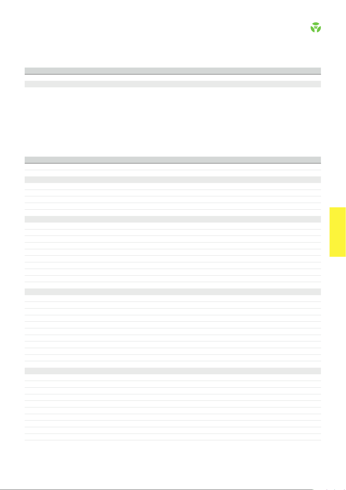
CIRCUIT DIAGRAM
SNO 4062K /KM
.
40
safe RE LAY
Page 2
OVERVIEW OF DEVICES | PART NUMBERS
Typ e Rated voltage Termi nals Part no. P.U .
SNO 4062K-A 24 V AC/DC R1.188.0700.2 1
SNO 4062KM-A 24 V AC/DC R1.188.0720.2 1
SNO 4062K-C 24 V AC/DC R1.188.2000.0 1
TECHNICAL DATA
Function Emergency stop relay
Function display 3 LEDs, green
Power supply circuit
Rated voltage U
N
A1, A2 24 V AC/DC
Rated consumption 24 V DC (K / KM) 2.0 W / 2.1 W
Rated frequency 50 - 60 Hz
Operating voltage range U
B
Electrical isolation supply circuit - control circuit no
Control circuit
Rated output voltage S11, S33/S21 22 V DC
Input current / peak current S12, S31/S22 40 mA / 100 mA
S34, S35 5 mA / 50 mA
Response time t
Minimum ON time t
Recover y time t
Release time t
Synchronous time t
Permissable test pulse time t
Max. resistivit y, per channel
/ t
A1
A2
M
W
R
S
TP
1)
Output circuit
Enabling paths 13/14, 23/24 normally open contact
Signaling paths 31/32 normally closed contact
Contact assignment forcebly guided
Contact type Ag-alloy, gold-plated
Rated switching voltage enabling / signaling path 230 V AC
Max. thermal current I
th
enabling / signaling path 6 A / 3 A
Max. total current I² of all current path (Tu = 55 ºC) 9 A²
Application category (NO) AC-15 U
DC-13 U
Short-circuit protection (NO), lead fuse / circuit breaker 6 A class gG / melting integral < 100 A²s
Mechanical life 10
General data
Creepage distances and clearances between the circuits EN 6066 4-1
Protection degree according to EN 60529 (housing / terminals) IP40 / IP20
Ambient temperature / storage temperature -25 ºC - +55 ºC / -25 ºC - + 75 ºC
Wire ranges screw terminals, fine-stranded / solid 1 x 0.2 mm² – 2.5 mm² / 2 x 0.2 mm² – 1.0 mm²
fine-stranded with ferrules 1 x 0.25 mm² – 2.5 mm² / 2 x 0.25 mm² – 1.0 mm²
Permissible torque 0.5 - 0.6 Nm
Wire ranges push-in terminals 1 x 0.25 mm² – 1.5 mm²
Weight 24 V AC/DC device / AC device 0.21 kg
Standards EN ISO 13849-1, EN 62061
Approvals DGUV, cULus, CCC
1)
If two-channel devices are installed as single channel, the value is halved.
Screw terminals, pluggable
Screw terminals, pluggable
Push-in terminals, plug gable
0,85 - 1,1 x U
40 ms / 500 ms (KM: 40 ms / 80 ms)
50 ms
150 ms
< 25 ms
200 ms (CH1 → CH2)
< 1ms
≤ (5 + (1.176 x UB / UN - 1) x 100) Ω
230 V, Ie 3 A
e
24 V, Ie 2.5A
e
7
switching cycles
N
safe REL AY
safe RE LAY
.
41
 Loading...