

Wieland SNO 4003K Catalog Page
SNO 4003K
MONITORING OF EMERGENCY STOP AND SAFETY GATES
APPLICATIONS
• Protection of people and machinery
• Monitoring of emergency stop applications
• Monitoring of safety gates
• Up to PL d / Category 3 (EN ISO 13849-1)*
• Up to SIL
FEATURES
• Stop Category 0 according to EN 60204-1
• Single-channel or two-channel control
• Manual or automatic start
• 3 enabling current paths, 1 signal current path
• Feedback loop for monitoring external contactors
* PL e contact expansion
@ Y t
2 (EN 62061)*
CL
FUNCTION
The device is a single-channel switching device for emergency stop
applications with self-monitoring on each ON-OFF cycle. It
complies with EN 60204-1 and is equipped with forcibly guided
relays.
The device has either two Y2 reset inputs (without reset
monitoring) or two Y3 reset inputs (with reset monitoring). The K1
and K2 relays are actuated eitherautomatically (bridge Y1 Y2) or
after the reset button (on Y1 Y3) has been pressed. They become
self-locking through their own contacts, if there is an electrical
connection between terminal A1 and the supply voltage
(emergency stop button, position switches).
After this switch-on phase the enabling current paths are closed
and the signaling current path is open.
If the electrical connections between terminal A1 and the supply
voltage are interrupted, the enabling current paths open and the
signaling current path closes. The energized state (self-locking) of
the two channels is indicated by a green LED K1, K2. The second
green LED indicates that supply voltage has been applied. The
set-up of an emergency stop facility after stop Category 0 (EN
60204-1) is possible.
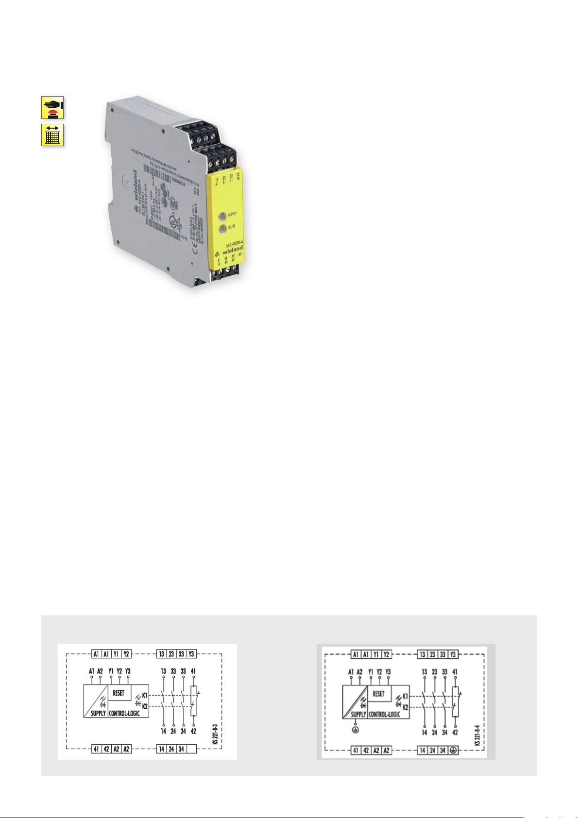
CIRCUIT DIAGRAM
SNO 4003K 24 V AC/DC 115-120 V AC / 230 V AC
.
48
safe RE LAY

OVERVIEW OF DEVICES | PART NUMBERS
Typ e Rated voltage Ter minal s Part no. P.U .
SNO 4003K-A 24 V AC/DC R1.188.0500.1 1
115 – 120 V AC R1.188.0900.1 1
230 V AC R1.188.0910.1 1
SNO 4003K-C 24 V AC/DC R1.188.1990.0 1
115 – 120 V AC R1.188.4000.0 1
230 V AC R1.188.4010.0 1
TECHNICAL DATA
Function Emergency stop relay
Function display 2 LEDs, green
Power supply circuit
Rated voltage U
N
A1, A2 24 V AC/DC / 115-120 V AC / 230 V AC
Rated consumption 24 V DC 1.3 W
115-120 V AC, 230 V AC 2.2 W / 3.9 VA
Rated frequency 50 - 60 Hz
Operating voltage range U
B
Electrical isolation supply circuit - control circuit yes (at UN = 115-120 V AC, 230 V AC)
Control circuit
Rated output voltage Y1 24 V DC
Input current / peak current Y2, Y3 90 mA / 1500 mA
Response time t
Minimum ON time t
Recover y time t
Release time t
/ t
A1
A2
(Manueller Star t) 60 ms
M
W
R
Max. resistivit y 24V AC/DC ≤ (2.5 + (1.176 x U
115-120 V AC, 230 V AC ≤ (7.5 + (1.176 x U
Output circuit
Enabling paths 13/14, 23/24, 33/34
Signaling paths 41/42 normally closed contact
Contact assignment forcebly guided
Contact type Ag-alloy, gold-plated
Rated switching voltage enabling / signaling path 230 V AC
Max. thermal current I
th
enabling / signaling path 8 A / 5 A
Max. total current I² of all current path (Tu = 55 ºC) 9 A²
Application category (NO) AC-15 U
DC-13 U
Short-circuit protection (NO), lead fuse / circuit breaker 6 A class gG / melting integral < 100 A²s
Mechanical life 10
General data
Creepage distances and clearances between the circuits EN 6066 4-1
Protection degree according to EN 60529 (housing / terminals) IP40 / IP20
Ambient temperature / storage temperature -25 ºC - +55 ºC / -25 ºC - + 75 ºC
Wire ranges screw terminals, fine-stranded / solid 1 x 0.2 mm² – 2.5 mm² / 2 x 0.2 mm² – 1.0 mm²
fine-stranded with ferrules 1 x 0.25 mm² – 2.5 mm² / 2 x 0.25 mm² – 1.0 mm²
Permissible torque 0.5 - 0.6 Nm
Wire ranges push-in terminals 1 x 0.25 mm² – 1.5 mm²
Weight 24 V AC/DC device / AC device 0.20 kg / 0.25 kg
Standards EN ISO 13849-1, EN 62061
Approvals DGUV, cULus, CCC
Screw terminals, pluggable
Screw terminals, pluggable
Screw terminals, pluggable
Push-in terminals, pluggable
Push-in terminals, pluggable
Push-in terminals, pluggable
0.85 - 1.1 x U
60 ms
200 ms
60 ms
230 V, Ie 5 A
e
24 V, Ie 5A
e
7
switching cycles
N
/ UN - 1) x 50) Ω
B
/ UN - 1) x 150) Ω
B
safe REL AY
safe RE LAY
.
49
 Loading...