

Wieland SNO 1012K Catalog Page
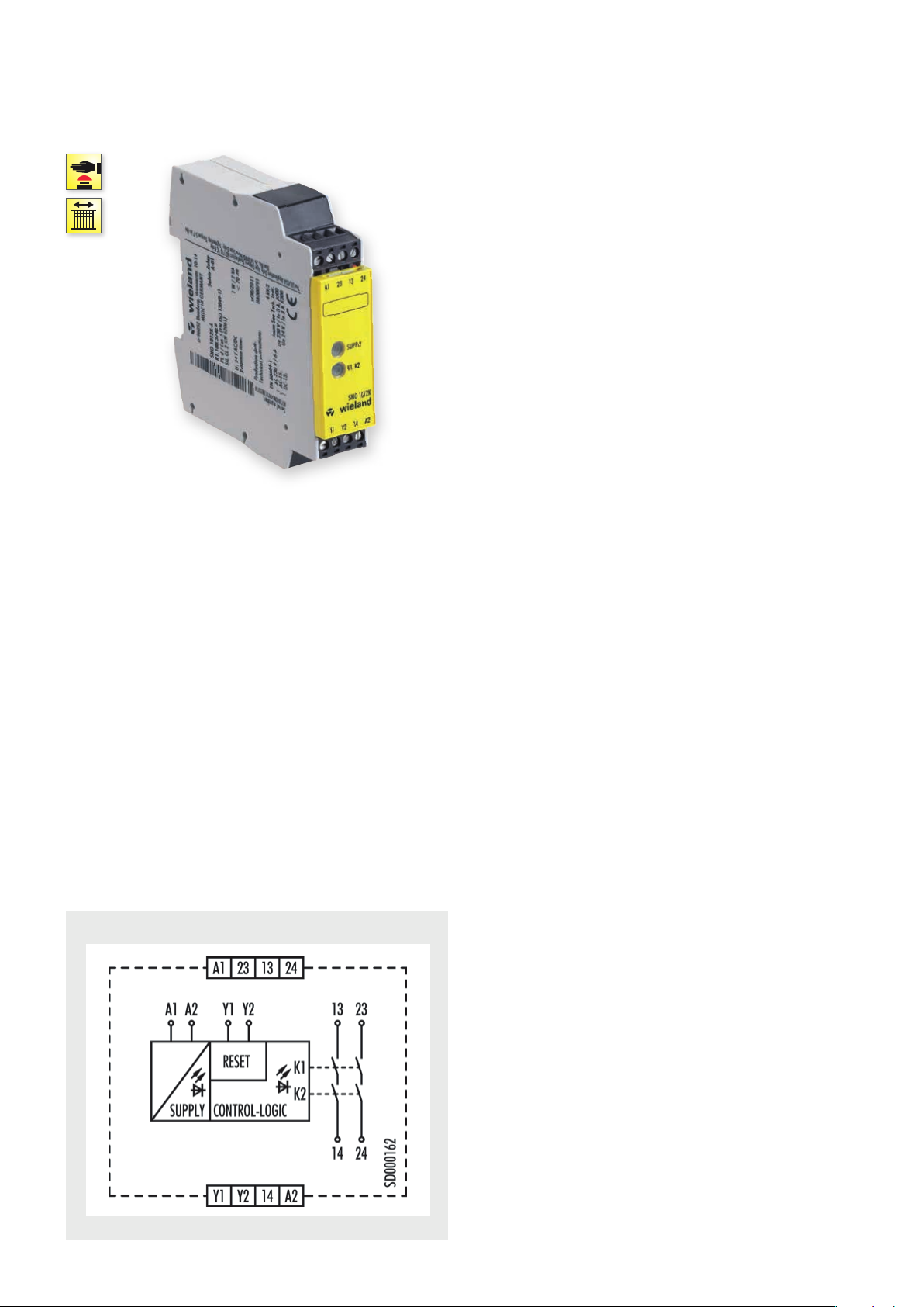
SNO 1012K
MONITORING OF EMERGENCY STOP AND SAFETY GATES
APPLICATIONS
• Protection of people and machinery
• Monitoring of emergency stop applications
• Monitoring of safety gates
• Up to PL d / Category 3 (EN ISO 13849-1)
• Up to SIL
FEATURES
• Stop Category 0 according to EN 60204-1
• Single-channel or two-channel control
• Manual or automatic start
• 2 enabling current paths
• Check of external contactors (EDM)
• Compact design
] Y t
2 (EN 62061)
CL
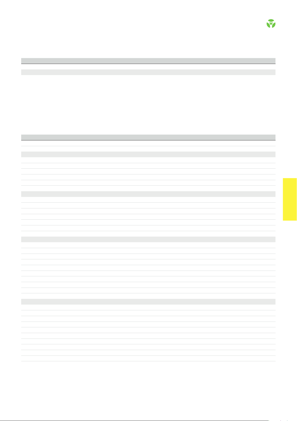
FUNCTION
After the operating voltage (L+/L1) is applied via an unactuated
emergency stop button or safety gate contact on A1 and A2, the
device can be switched on via a Y1/Y2-connected reset button.
When the device is on, the internal relays K1 and K2 are energized
and the enabling current paths 13/14 and 23/24 are closed. When
the emergency stop button or the safety gate contact is actuated,
the current supply of the internal relays is interrupted and the
enabling current paths are opened.
CIRCUIT DIAGRAM
SNO 1012K
.
50
safe RE LAY
OVERVIEW OF DEVICES | PART NUMBERS
Typ e Rated voltage Ter minal s Part no. P.U .
SNO 1012K-A 24 V AC/DC R1.188.3740.0 1
SNO 1012K-C 24 V AC/DC R1.188.3750.0 1
TECHNICAL DATA
Function Emergency stop relay
Function display 2 LEDs, green
Power supply circuit
Rated voltage U
N
A1, A2 24 V AC/DC
Rated consumption 24 V DC 1 W / 2 VA
Rated frequency 50 - 60 Hz
Operating voltage range U
B
Electrical isolation supply circuit - control circuit no
Control circuit
Rated output voltage Y1 24 V DC
Input current / peak current Y2 50 mA / 70 mA
Response time t
Minimum ON time t
Recover y time t
Release time t
/ t
A1
A2
M
W
R
Max. resistivit y ≤ (2.5 + (1.176 x U
Output circuit
Enabling paths 13/14, 23/24 normally open contact
Contact assignment forcebly guided
Contact type Ag-alloy, gold-plated
Rated switching voltage 240 V AC / 50V DC
Max. thermal current I
th
enabling path 6 A
Max. total current I² of all current path (Tu = 55 ºC) 72 A² / 9 A²
Application category (NO) AC-15 U
DC-13 U
Short-circuit protection (NO), lead fuse / circuit breaker 6 A class gG / melting integral < 100 A²s
Mechanical life 10 x 10
General data
Creepage distances and clearances between the circuits EN 60 664 -1
Protection degree according to EN 60529 (housing / terminals) IP40 / IP20
Ambient temperature / storage temperature -25 ºC - +55 ºC / -25 ºC - + 75 ºC
Wire ranges screw terminals, fine-stranded / solid 1 x 0.2 mm² – 2.5 mm² / 2 x 0.2 mm² – 1.0 mm²
fine-stranded with ferrules 1 x 0.25 mm² – 2.5 mm² / 2 x 0.25 mm² – 1.0 mm²
Permissible torque 0.5 - 0.6 Nm
Wire ranges push-in terminals 2 x 0.25 mm² – 1.5 mm²
Weight 0.12 kg
Standards EN ISO 13849-1, EN 62061
Approvals TÜV, cULus, CCC
Screw terminals, pluggable
Push-in terminals, pluggable
0.85 - 1.1 x U
N
< 20 ms / < 70 ms
30 ms
> 200 ms
< 70 ms
230 V, Ie 3 A
e
24 V, Ie 3 A
e
6
switching cycles
/ UN - 1) x 50) Ω
B
safe REL AY
safe RE LAY
.
51
 Loading...