

Wieland SNE 4012K, SNE 4024K Catalog Page
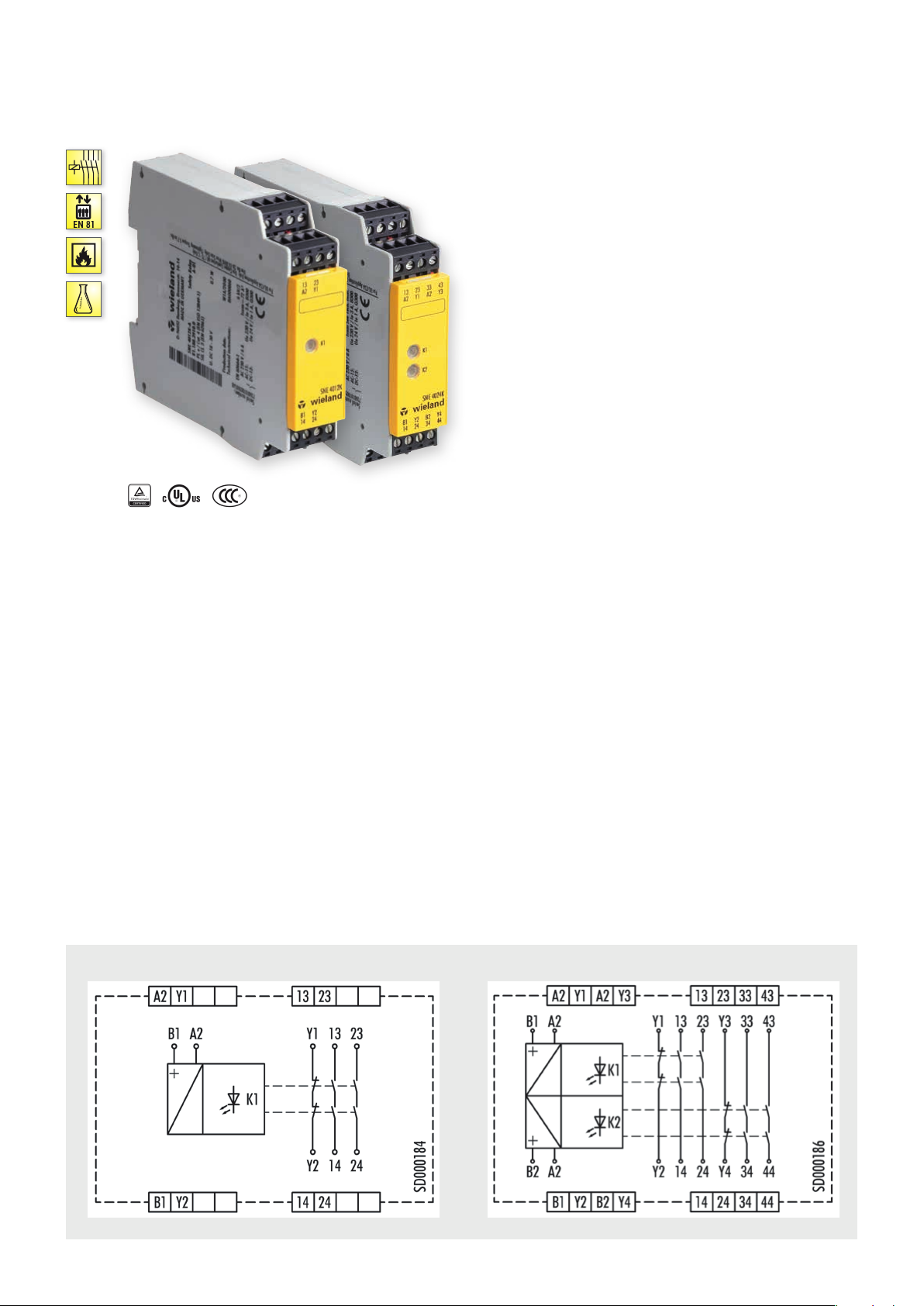
SNE 4012K / SNE 4024K
CONTACT EXPANSION
] Y t
APPLICATIONS
• Expansion of a basic device’s enabling current paths
• Contact expansion in safety equipment
• Up to PL e / Category 3 (EN ISO 13849-1)*
• Up to SIL
3 (EN 62061)*
CL
FEATURES
•
Stop Category 0 and 1 according to EN 60204-1 (see “Function”)
• Single-channel control
• SNE 4012K: 2 enabling current paths (NO contact)
• SNE 4024K: 2 x 2 enabling current paths (NO contact)
* Depends on the category of the basic device or the safety control.
FUNCTION
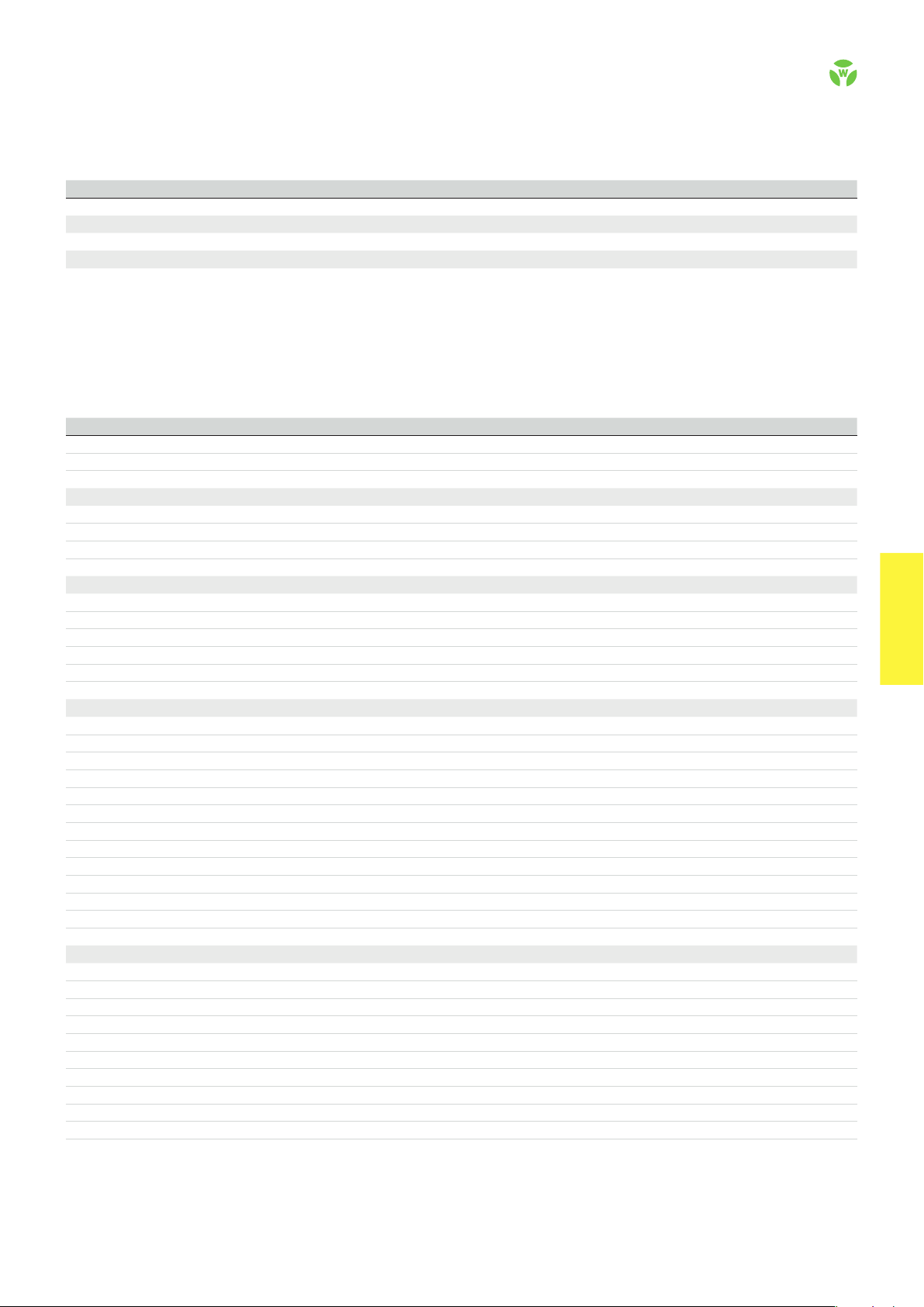
Once the supply voltage has been applied to terminals B1/A2 (B2/
A2), the enabling current paths (NOC) are automatically closed and
the signaling current paths (NCC) are opened.
When the supply voltage is ceased, the enabling current paths
(NOC) are immediately opened and the signaling current paths
(NCC) are immediately closed.
CIRCUIT DIAGRAMS
SNE 4012K
SNE 4024K
.
76
safe RE LAY
OVERVIEW OF DEVICES | PART NUMBERS
Typ e Rated voltage Ter minals Part no. P.U .
SNE 4012K-A 24 V DC R1.188.3910.0 1
SNE 4012K-C 24 V DC R1.188.3920.0 1
SNE 4024K-A 24 V DC R1.188.3930.0 1
SNE 4024K-C 24 V DC R1.188.3940.0 1
TECHNICAL DATA
Function Emergency stop expansion relay
Function display – SNE 4012K 1 LED, green
Function display – SNE 4024K 2 LED, green
Power supply circuit
Rated voltage U
N
B1/A2; B2/A2 24 V DC
Rated consumption – SNE 4012K 0.7 W
Rated consumption – SNE 4022K 1.4 W
Operating voltage range U
B
Control circuit
Input current / peak current B1/A2 ca. 30 mA / 110 mA
B2/A 2 ca. 30 mA / 110 mA
Response time t
Recover y time t
Release time t
Max. resistivity, per channel
/ t
A1
A2
W
R
1)
Output circuit
Enabling paths 13/14, 23/24 normally open contact
33/34, 43/44 normally open contact
Signaling paths Y1/Y2 normally closed contact
Y3/ Y4 normally closed contact
Contact assignment forcebly guided
Contact type Ag-alloy
Rated switching voltage 230 V AC, 24 V DC
Max. thermal current I
Max. total current I
Max. total current I
2
of all current path – SNE 4012K (Tu = 55 ºC) 72 A²
2
of all current path – SNE 4024K (Tu = 55 ºC) 2 x 72 A² / 2 x 8 A²
th
enabling / signaling path 6 A
Application category (NO) AC-15 | DC-13 U
Short-circuit protection (NO), lead fuse / circuit breaker 6 A class gL / melting integral < 100 A²s
Mechanical life 10 x 10
General data
Creepage distances and clearances bet ween the circuits EN 60 664 -1
Protection degree according to EN 60529 (housing / terminals) IP40 / IP20
Ambient temperature / storage temperature -25 ºC - +65 º C / -25 ºC - + 75 ºC
Wire ranges screw terminals, fine-stranded / solid 1 x 0.2 mm² – 2.5 mm² / 2 x 0.2 mm² – 1.0 mm²
fine-stranded with ferrules 1 x 0.25 mm² – 2.5 mm² / 2 x 0.25 mm² – 1.0 mm²
Permissible torque 0.5 - 0.6 Nm
Wire ranges push-in terminals 1 x 0.25 mm² – 1.5 mm²
Weight 0.180 kg
Standards EN ISO 13849-1, EN 62061, DIN EN 50156-1, EN 61511
Approvals TÜV, cULus, CCC
1)
If two-channel devices are installed as single channel, the value is halved.
Screw terminals, pluggable
Push-in terminals, pluggable
Screw terminals, pluggable
Push-in terminals, pluggable
0.75 - 1.25 U
< 15 ms
≤ 30 ms
≤ 15 ms
≤ (5 + (1,333 x UB / UN - 1) x 200) Ω
230 V, Ie 3 A | Ue 24 V, Ie 1 A
e
6
switching cycles
N
safe REL AY
safe RE LAY
.
77
 Loading...