

Wieland SNE 4004K, SNE 4004KV Catalog Page
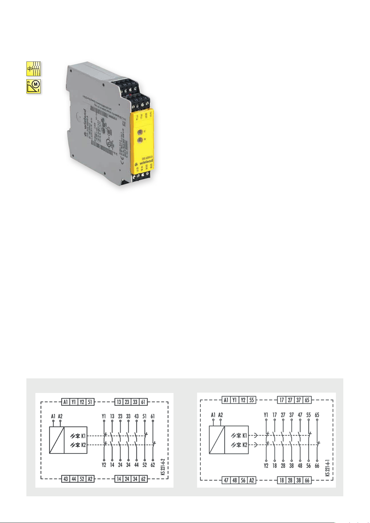
SNE 4004K/KV
CONTACT EXPANSION
@ Y t
APPLICATIONS
• Expansion of a basic device’s enabling current paths
• Contact expansion in safety equipment
• Up to PL d / Category 3 (EN ISO 13849-1)*
• Up to SIL
2 (EN 62061)*
CL
FEATURES
•
Stop Category 0 and 1 according to EN 60204-1 (see “Function”)
• Single-channel or two-channel control
• SNE 4004K: 4 enabling current paths, undelayed
(NO contact)
3 signaling curent paths, undelayed
(NC contact)
• SNE 4004KV: 4 enabling current paths, OFF-delayed
(NO contact)
3 signaling current paths, OFF-delayed
(NC contact),
Time buffering
* Depends on the category of the basic device or the safet y control.
FUNCTION
SNE 4004K
Supply voltage to the SNE devices is routed via an enabling current
path of a basic device. When the supply voltage is applied relays K1
and K2 switch into the ON position. After this switch-on phase the
four enabling current paths 13/14, 23/24, 33/34, 43/44 (of the SNE
4004K) or 17/18, 27/28, 37/38, 47/48 (of the SNE 4004KV) are closed
and the feedback current path Y1/Y2 is open. This is displayed
through two LEDs that are assigned to relays K1 and K2.
When the enabling current paths of the basic device are opened
through the operation of the emergency stop button, relays K1 and
K2 on the SNE 4004K switch back into the OFF-position. The
enabling current paths open and the feedback current path closes.
Feedback current path Y1/Y2 prevents the basic device from
switching on again before K1 or K2 releases.
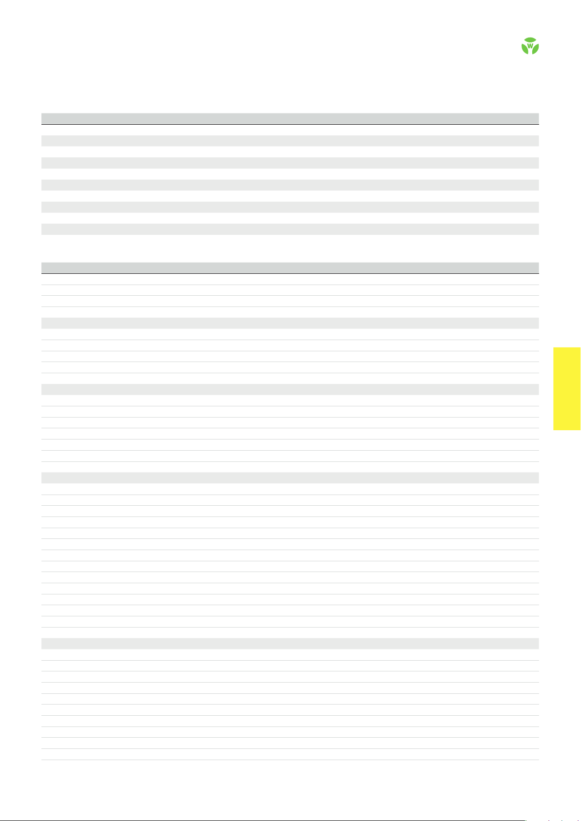
CIRCUIT DIAGRAMS
SNE 4004K
SNE 4004KV
The functions of this device correspond to those of the SNE 4004K.
The SNE 4004KV is available with the following four OFF-delay
times t
that is enabled through capacitors.
This causes the OFF-delay time t
case of failure of the power supply (A1/A2). It cannot be reset before
it has elapsed. Once the delay time has elapsed, relays K1 and K2
switch into the OFF- position. OFF-delay times of > 0 s correspond
to stop category 1.
: 0.5 s; 1 s; 2 s and 3 s. The device has an OFF-delay time
R1
to elapse completely even in
R1
SNE 4004KV
.
74
safe RE LAY
OVERVIEW OF DEVICES | PART NUMBERS
Typ e Time range Rated voltage Ter minal s Part no. P.U .
SNE 4004K-A – 24 V AC/DC R1.188.0590.0 1
SNE 4004K-C – 24 V AC/DC R1.188.1980.0 1
SNE 4004KV-A 24 V DC R1.188.0460.0 1
0.5 s Screw terminals, pluggable
1 s 24 V DC R1.188.0470.0 1
2 s 24 V DC R1.188.0480.0 1
3 s 24 V DC R1.188.0490.0 1
SNE 4004KV-C 24 V DC R1.188.2410.0 1
0.5 s Push-in terminals, pluggable
1 s 24 V DC R1.188.2420.0 1
2 s 24 V DC R1.188.2430.0 1
3 s 24 V DC R1.188.2440.0 1
TECHNICAL DATA
Function Emergency stop expansion relay
Function display 2 LEDs, green
Function mode / adjustment Time, fixed
Adjustment range 0,5 s / 1 s / 2 s / 3 s
Power supply circuit
Rated voltage U
N
A1, A2 24 V DC / 24 V AC/DC
Rated consumption 24 V DC | 24 V AC/DC 1.2 W | 1.7 W / 3.1 VA
Rated frequency 50 - 60 Hz
Operating voltage range U
B
Electrical isolation supply circuit - control circuit non
Control circuit
Input current / peak current A1, A2 65 mA / 1800 mA
Response time t
Minimum ON time t
Recover y time t
Release time t
Release time t
Max. resistivit y, per channel
/ t
A1
A2
M
W
R
, delayed contacts (tolerance) 0.5 s / 1 s / 2 s / 3 s (± 35 %)
R
1)
Output circuit
Enabling paths 13/14, 23/24, 33/34, 43/44 normally open contact
17/17, 27/28 , 37/ 38 , 47/48 normally open contact, time delayed
Signaling paths 51/52, 61/62 normally closed contact
55/56, 65/66 normally closed contact, time delayed
Contact assignment forcebly guided
Contact type Ag-alloy, gold-plated
Rated switching voltage enabling / signaling path 230 V AC
Y1/Y2 230 V AC
Max. thermal current I
th
enabling / signaling path 6 A / 2 A
Y1/Y2 2 A
Max. total current I
2
of all current path (Tu = 55 ºC) 9 A²
Application category (NO) AC-15 | DC-13 U
Short-circuit protection (NO), lead fuse / circuit breaker 6 A class gG / melting integral < 100 A²s
Mechanical life 10
General data
Creepage distances and clearances between the circuits EN 60664 -1
Protection degree according to EN 60529 (housing / terminals) IP40 / IP20
Ambient temperature / storage temperature -25 ºC - +55 ºC / -25 ºC - + 75 ºC
Wire ranges screw terminals, fine-stranded / solid 1 x 0.2 mm² – 2.5 mm² / 2 x 0.2 mm² – 1.0 mm²
fine-stranded with ferrules 1 x 0.25 mm² – 2.5 mm² / 2 x 0.25 mm² – 1.0 mm²
Permissible torque 0,5 - 0,6 Nm
Wire ranges push-in terminals 1 x 0.25 mm² –1.5 mm²
Weight 0.20 kg
Standards EN ISO 13849-1, EN 62061
Approvals DGUV, cULus, CCC
1)
If two-channel devices are installed as single channel, the value is halved.
Screw terminals, pluggable
Push-in terminals, pluggable
Screw terminals, pluggable
Screw terminals, pluggable
Screw terminals, pluggable
Push-in terminals, pluggable
Push-in terminals, pluggable
Push-in terminals, pluggable
0.85 - 1.1 x U
N
20 ms
0,15 x t
R
≤ 200 ms
40 ms
≤ (2.5 + (1.176 x UB / UN - 1) x 50) Ω
230 V, Ie 5 A | Ue 24 V, Ie 5 A
e
7
switching cycles
safe REL AY
safe RE LAY
.
75
 Loading...