

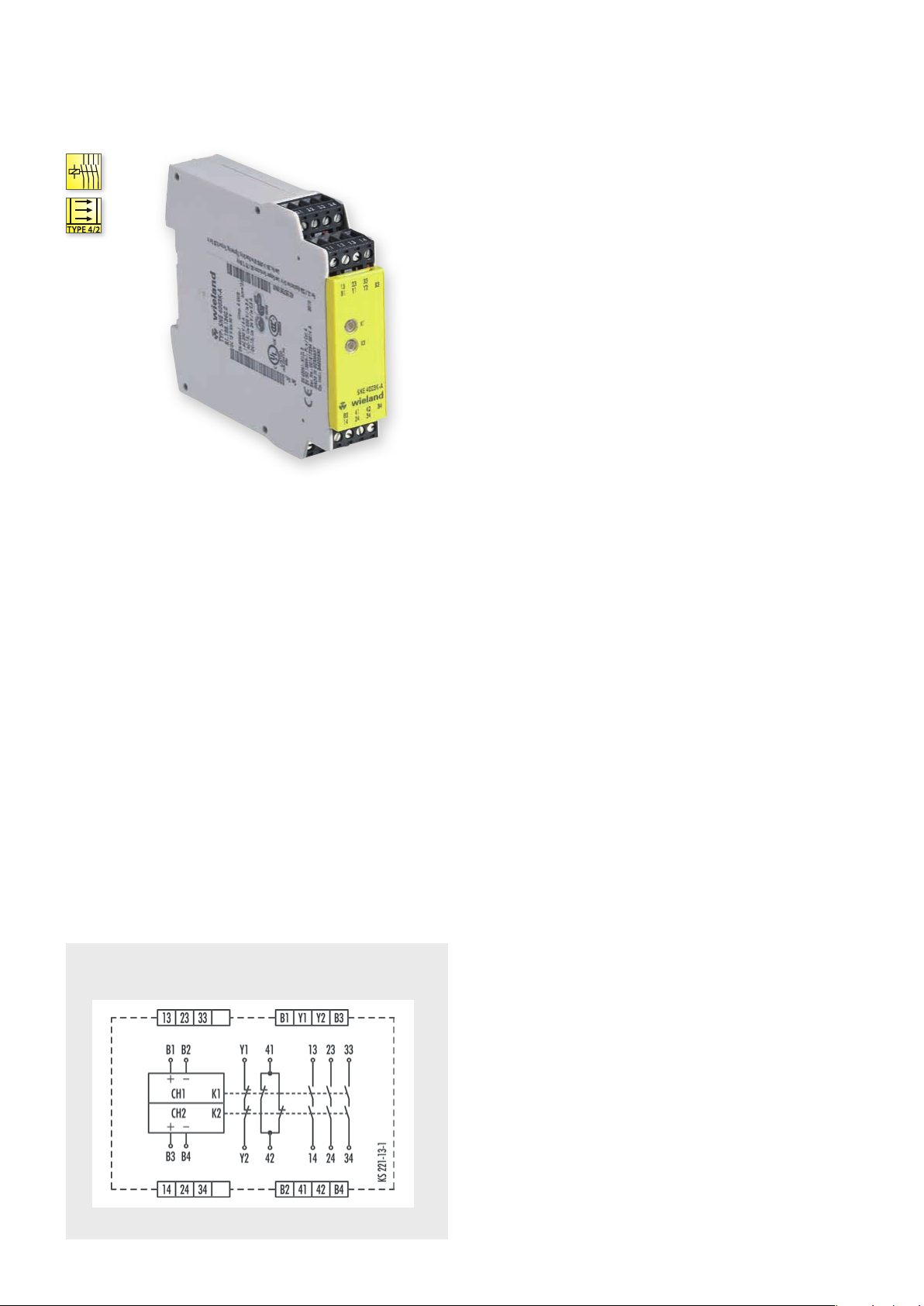
SNE 4003K
CONTACT EXPANSION
@ Y t
APPLICATIONS
• Duplication of the enabling current paths of a basic device
• Contact expansion in safety-oriented systems
• Contact expansion for light curtains
• Up to PL e / Category 4 (EN ISO 13849-1)*
• Up to SIL
3 (EN 62061)*
CL
FEATURES
• Single-channel or two-channel operation
• 3 enabling current paths (NO contact)
• 2 signaling current paths (NC contact)
• Wide input voltage range from 15 to 30 V DC
• Suitable for semiconductor outputs
* Depends on the category of the basic device or the safety control.
FUNCTION
The SNE 4003K is an expansion device for basic devices (such as
safety switching devices, light curtains, laser scanners) that are
part of the machine’s safety equipment and are used for protecting
people, materials and machines.
The device is designed with two channels and redundancy. There is
basic insulation to separate the enabling current paths from one
another and the control circuits from the signaling current paths.
The broad input voltage range of 15 V DC to 30 V DC makes the
SNE 4003K ideal for single-channel or two-channel control by
semiconductors.
CIRCUIT DIAGRAM
SNE 4003K
Input voltage to the SNE 4003K is connected via one or two
enabling current paths of a basic device. When the input voltage is
applied relays K1 and K2 switch into the ON position. After this
switch-on phase, enabling current paths 13/14, 23/24, 33/34 are
closed and feedback current path Y1/Y2 and signaling current path
41/42 are opened.
This is displayed through two LEDs, K1 and K2, which are assigned
to relays K1 and K2. If the enabling current paths of the basic device
are opened when the emergency stop button is pressed, relays K1
and K2 on the SNE 4003K switch back into the OFF-position. The
enabling current paths open and the feedback current path closes.
Feedback current path Y1/Y2 prevents the basic device from
switching on again before K1 or K2 releases.
.
72
safe RE LAY
OVERVIEW OF DEVICES | PART NUMBERS
Typ e Rated voltage Ter minals Part no. P.U .
SNE 4003K-A 24 V DC R1.188.1340.0 1
SNE 4003K-C 24 V DC R1.188.4210.0
TECHNICAL DATA
Function Emergency stop expansion relay
Function display 2 LEDs, green
Power supply circuit
Rated voltage U
N
B1/B2, B3/B4 24 V DC
Rated consumption 24 V DC 1.2 W
Operating voltage range U
B
Electrical isolation supply circuit - control circuit no
Control circuit
Input current / peak current B1/B2, B3/B4 50 mA / 500 mA
Response time t
Recover y time t
Release time t
Permissable test pulse time t
Max. resistivity, per channel
/ t
A1
A2
W
R
TP
1)
Output circuit
Enabling paths 13/14, 23/24, 33/34 normally open contact
Signaling paths 41/42 normally closed contact
Contact assignment forcebly guided
Contact type Ag-alloy, gold-plated
Rated switching voltage enabling- / signaling path 230 V AC
Y1/Y2 230 V AC
Max. thermal current I
th
enabling- / signaling path 6 A / 2 A
Y1/Y2 2 A
Max. total current I
2
of all current path (Tu = 55 ºC) 9 A²
Application category (NO) AC-1 5 U
DC-13 U
Short-circuit protection (NO), lead fuse / circuit breaker 6 A class gG / melting integral < 100 A²s
Mechanical life 10
General data
Creepage distances and clearances bet ween the circuits EN 6 066 4-1
Protection degree according to EN 60529 (housing / terminals) IP40 / IP20
Ambient temperature / storage temperature -25 ºC - +55 ºC / -25 ºC - + 75 ºC
Wire ranges screw terminals, fine-stranded / solid 1 x 0.2 mm² – 2.5 mm² / 2 x 0.2 mm² – 1.0 mm²
fine-stranded with ferrules 1 x 0.25 mm² – 2.5 mm² / 2 x 0.25 mm² – 1.0 mm²
Permissible torque 0.5 - 0.6 Nm
Wire ranges push-in terminals 1 x 0.25 mm² – 1.5 mm²
Weight 0,21 kg
Standards EN ISO 13849-1, EN 62061
Approvals DGUV, cULus, CCC
1)
If two-channel devices are installed as single channel, the value is halved.
Screw terminals, pluggable
Push-in terminals, pluggable
0.63 - 1.25 x U
< 40 ms
≤ 40 ms
< 20 ms
< 1 ms
≤ (5 + (1.6 x UB / UN - 1) x 100) Ω
230 V, Ie 3 A
e
24 V, Ie 2,5 A
e
7
switching cycles
N
1
safe REL AY
safe RE LAY
.
73
 Loading...