

Page 1
SNE 1
CONTACT EXPANSION
a
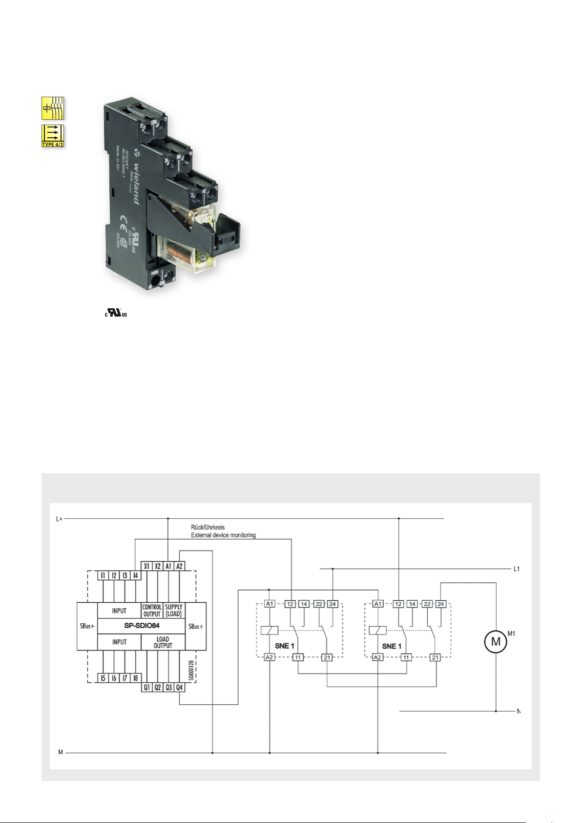
APPLICATIONS
• Duplication of the enabling current paths of
a basic device
• Contact expansion in safety-oriented systems
• Up to PL e / Category 4 (EN ISO 13849-1)*
• Up to SIL
FEATURES
• Stop Category 0 and 1 according to EN 60204-1
• Single-channel operation
• 2 changeover contacts (positively driven)
• Sturdy retaining bracket
* Depends on the category of the basic device or the safet y control.
3 (EN 62061)*
CL
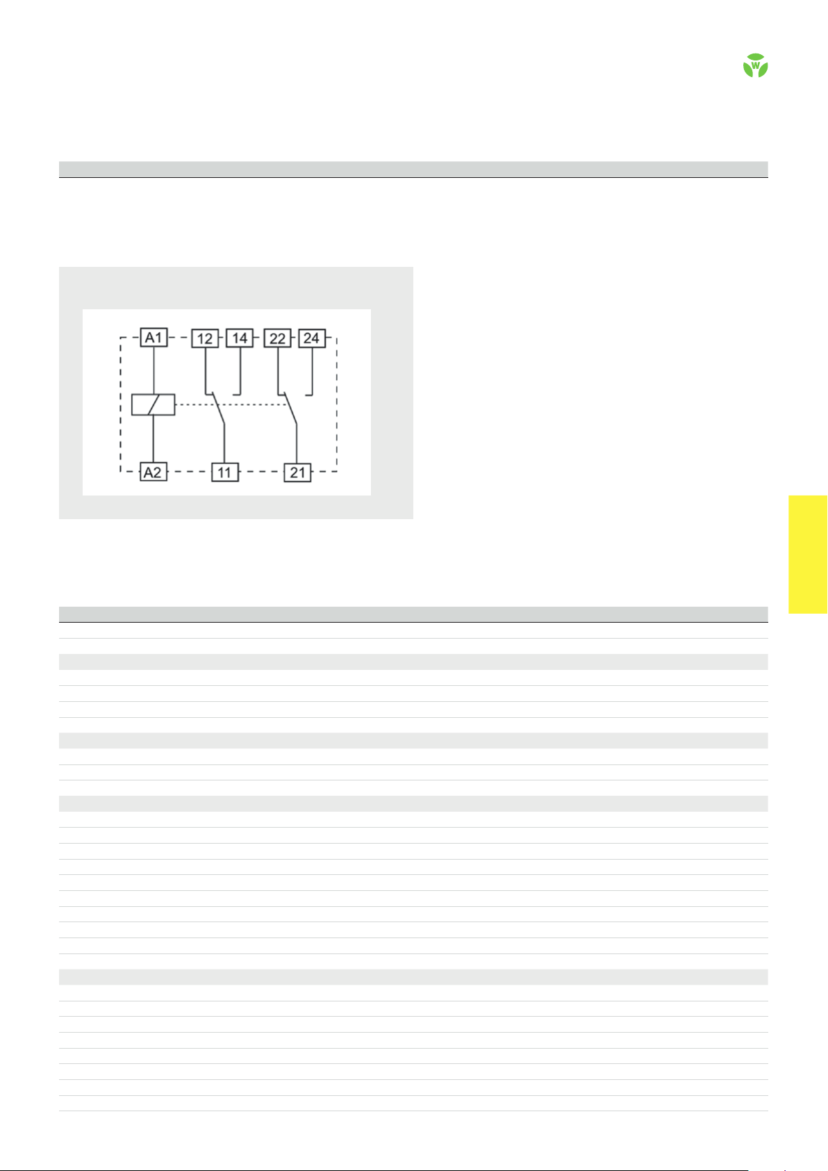
CIRCUIT DIAGRAM
SNE 1
.
70
safe RE LAY
Page 2
OVERVIEW OF DEVICES | PART NUMBERS
Typ e Rated voltage Ter minal s Part no. P.U .
SNE 1 24 V DC R1.188.3950.0 1
Screw terminals
CIRCUIT DIAGRAM
SNE 1
TECHNICAL DATA
Function Emergency stop expansion relay
Function display none
Power supply circuit
Rated voltage U
N
A1/A 2 24 V DC
Rated consumption 0.7 W
Operating voltage range U
B
0.63 - 1.25 x U
N
Electrical isolation supply circuit - control circuit yes
Control circuit
Input current / peak current A1/A2 ca. 29 mA
Response time t
Release time t
/ t
A1
A2
R
12 ms
< 20 ms
Output circuit
Enabling paths 11/12/14, 21/22/24 changeover contact
Contact assignment forcebly guided
Contact type Ag-alloy
Rated switching voltage 230 V AC, 24 V DC
Max. thermal current I
Max. total current I
th
2
of all current path (Tu = 55 ºC) 72 A²
Application category (NO) AC-15 U
DC-13 U
8 A
230 V, Ie 2 A
e
24 V, Ie 3 A
e
Short-circuit protection (NO), lead fuse / circuit breaker 6 A class gL / melting integral < 100 A²s
Mechanical life 10 x 10
6
switching cycles
General data
Creepage distances and clearances between the circuits EN 61810 -5
Protection degree according to EN 60529 (housing / terminals) IP20 / IP20
Ambient temperature / storage temperature -40 ºC - +70 ºC / -40 ºC - + 70
Wire range fine-stranded / solid 0.25 mm² – 4.0 mm² (AWG 24-12) / 0.25 – 6.0 mm
Permissible torque 0.5 Nm
Weight 0.06 kg
Standards EN 50205 (Type B)
Approvals cURus
2
(AWG 24-10)
safe REL AY
safe RE LAY
.
71
 Loading...