

Page 1
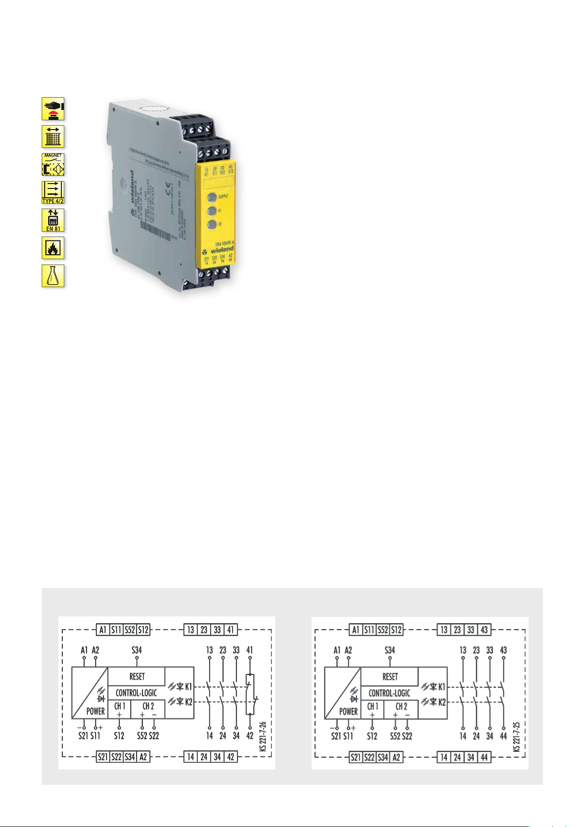
SNA 4063K/KM, SNA 4064K/KM
MONITORING OF EMERGENCY STOP, SAFETY GATES AND LIGHT BARRIERS
APPLICATIONS
• Monitoring of emergency stop applications
• Monitoring of safety gates
• Monitoring of light barriers
• Up to PL e / Category 4 (EN ISO 13849-1)
• Up to SIL
FEATURES
• Stop Category 0 according to EN 60204-1
• Single-channel or two-channel control
• Manual reset with monitoring
• Cross monitoring
• 3 to 4 enabling current paths
] Y t L
3 (EN 62061)
CL
FUNCTION
After the supply voltage is applied to terminals A1/A2 and the
safety inputs are closed, the enabling current paths (NO contacts)
are closed and the signal current path (NC contact) is opened by
pressing the reset button (manual start with monitoring). When the
safety inputs are opened/de-energized, the enabling current paths
(NO contacts) are opened immediately.
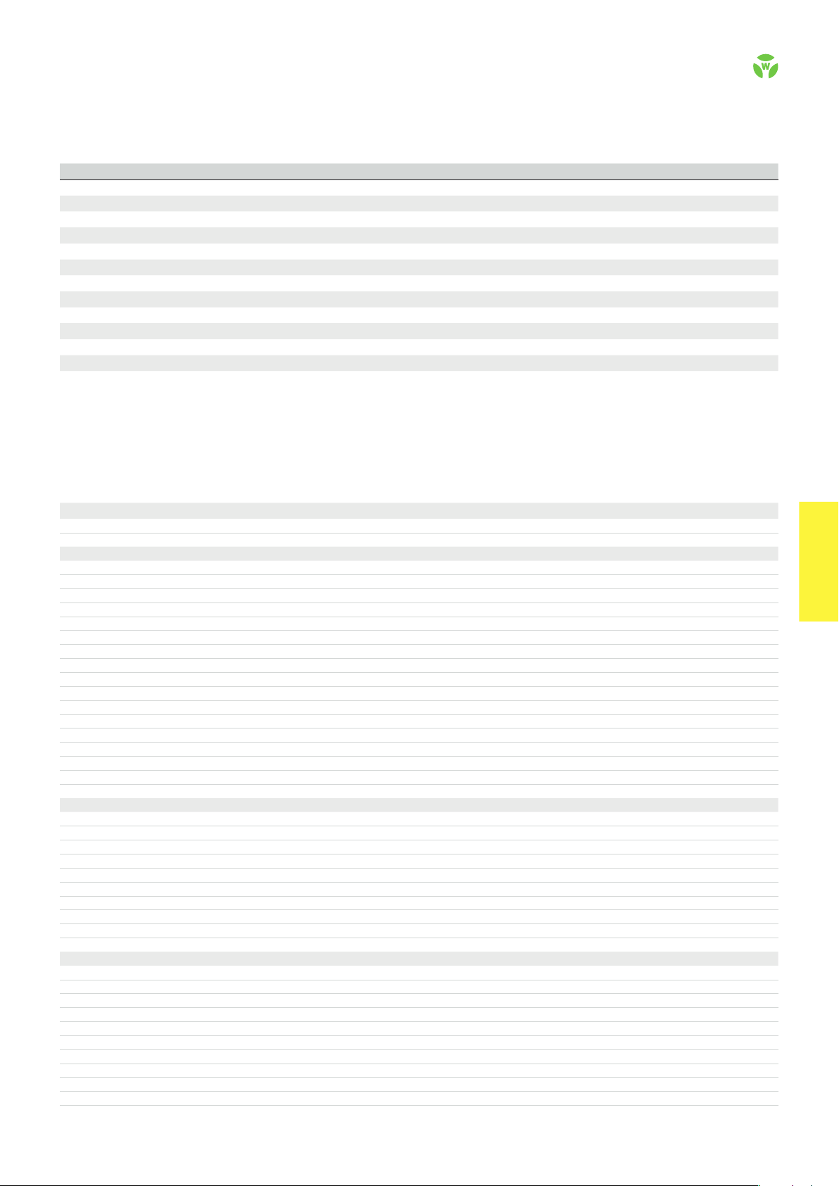
CIRCUIT DIAGRAM
• Manual start with monitoring – Reset input S34 is connected to
safety input S11 via a RESET button. To monitor external contact
blocks (EDM), their NC contacts must be connected in series to
the RESET button.
• Monitoring of light curtains – The KM device types are especially suitable for the monitoring of very fast tactile switching
operations, for example in safety light curtain applications. Very
short switch-off procedures of a few milliseconds are detected
reliably and lead to the switching off of the internal relays.
SNA 4064K/KMSNA 4063K/KM
.
46
safe RE LAY
Page 2
OVERVIEW OF DEVICES | PART NUMBERS
Typ e Rated voltage Terminal s Part no. P.U .
SNA 4063K-A 24 V AC/DC R1.188.1440.0 1
SNA 4063K-A 115-120 V AC R1.188.1450.0 1
SNA 4063K-A 230 V AC R1.188.1460.0 1
SNA 4063K-C 24 V AC/DC R1.188.1950.0 1
SNA 4063KM-A 24 V AC/DC R1.188.3290.0 1
SNA 4063KM-C 24 V AC/DC R1.188.3420.0 1
SNA 406 4K-A 24 V AC/DC R1.188.1900.0 1
SNA 406 4K-A 115-120 V AC R1.188.1920.0 1
SNA 406 4K-A 230 V AC R1.188.1930.0 1
SNA 406 4K-C 24 V AC/DC R1.188.1970.0 1
SNA 4064KM-A 24 V AC/DC R1.188.3360.0 1
SNA 4064KM-C 24 V AC/DC R1.188.3430.0 1
TECHNICAL DATA
Function Emergency stop relay
Function display 3 LEDs, green
Power supply circuit
Rated voltage U
N
A1, A2 24 V AC/DC / 115-120 V AC / 230 V AC
Rated consumption 24V DC / 24 V AC 1.6 W / 2.9 VA
42-48V AC / 115 -120V AC / 230 V AC 2.3 W / 2.6 VA
Rated frequency 50 - 60 Hz
Operating voltage range U
B
Electrical isolation supply circuit - control circuit yes (at UN = 115-230 V AC, 230 V AC)
Control circuit
Rated output voltage S11/S21 24 V DC
Input current / peak current S12, S52/S22 | S34 25 mA / 100 mA | 5 mA / 50 mA
Response time t
Minimum ON time t
Recover y time t
Release time t
Synchronous time t
Permissable test pulse time t
Max. resistivity, per channel
Output circuit
/ t
A1
A2
M
W
R
S
TP
1)
SNA 4063K/KM SNA 406 4K/KM
Enabling paths 13/14, 23/24, 33/34 13/14, 23/24, 33/34, 43/44 normally open contact
Signaling paths 41/42 --- normally closed contact
Contact assignment forcebly guided
Contact type Ag-alloy, gold-plated
Rated switching voltage enabling / signaling path 230 V AC
Max. thermal current I
th
enabling / signaling path 8 A / 5 A
Max. total current I² of all current path (Tu = 55 ºC) / (Tu = 65 ºC) 25 A² / 9 A²
Application category (NO) AC-15 | DC-1 3 U
Short-circuit protection (NO), lead fuse / circuit breaker 6 A class gG / melting integral < 100 A²s
Mechanical life 10
General data
Creepage distances and clearances between the circuits EN 60 664 -1
Protection degree according to EN 60529 (housing / terminals) IP40 / IP20
Ambient temperature / storage temperature -25 ºC - +65 º C / -25 ºC - + 75 ºC
Wire ranges screw terminals, fine-stranded / solid 1 x 0.2 mm² – 2.5 mm² / 2 x 0.2 mm² – 1.0 mm²
fine-stranded with ferrules 1 x 0.25 mm² – 2.5 mm² / 2 x 0.25 mm² – 1.0 mm²
Permissible torque 0-5 - 0-6 Nm
Wire ranges push-in terminals 1 x 0-25 mm² bis 1-5 mm²
Weight 24 V AC/DC device / AC device 0-21 kg / 0-25 kg
Standards EN ISO 13849-1, EN 62061, EN 81-20/50, EN 50156-1, EN 61511
Approvals TÜV, cULus, CCC, GL
1)
If two-channel devices are installed as single channel, the value is halved.
Screw terminals, pluggable
Screw terminals, pluggable
Screw terminals, pluggable
Push-in terminals, pluggable
Screw terminals, pluggable
Push-in terminals, pluggable
Screw terminals, pluggable
Screw terminals, pluggable
Screw terminals, pluggable
Push-in terminals, pluggable
Screw terminals, pluggable
Push-in terminals, pluggable
0.85 - 1.1 x U
N
100 ms / --100 ms
750 ms
10 ms
no
< 1 ms
24V AC/DC ≤ (5 + (1,176 x UB / UN - 1) x 100) Ω
42-48V AC/ 115-120 V AC, 230 V AC
≤ (5 + (1,176 x UB / UN - 1) x 100) Ω
230 V, Ie 3 A | Ue 24 V, Ie 3 A
e
7
switching cycles
safe REL AY
safe RE LAY
.
47
 Loading...