

Page 1
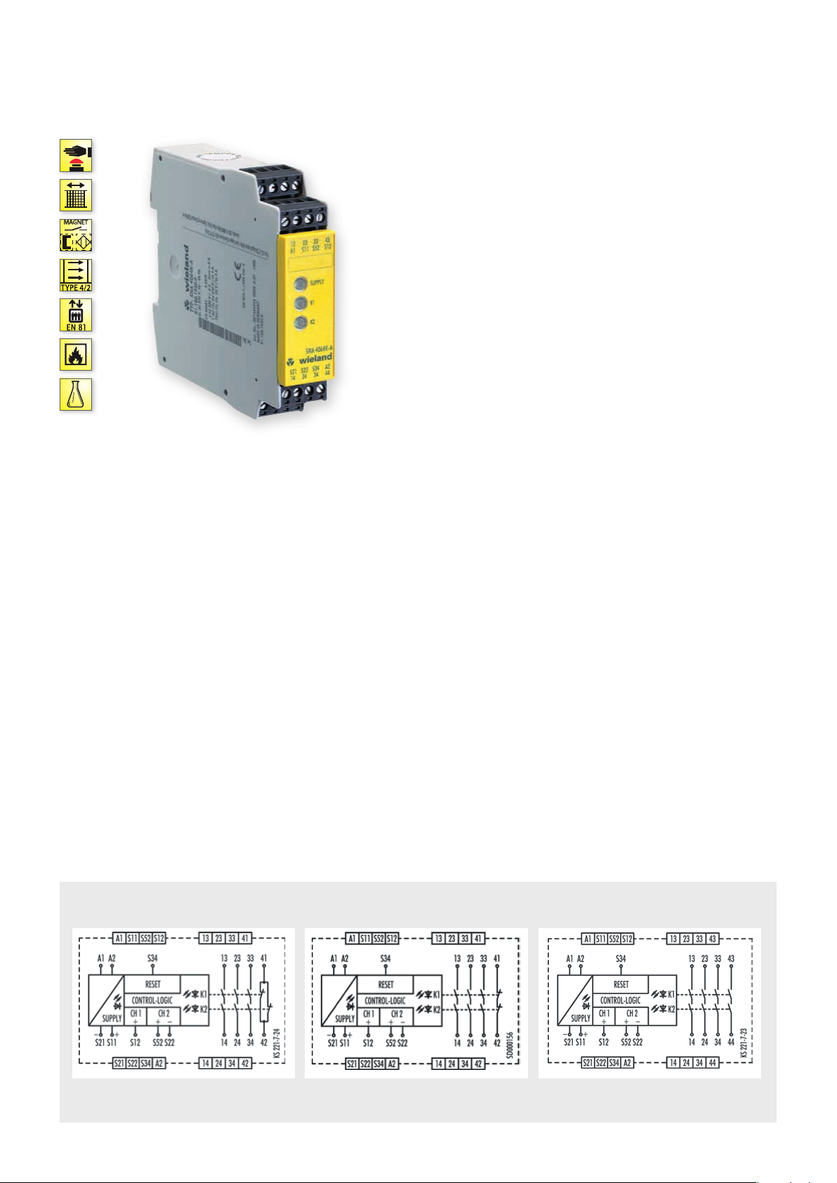
SNA 4043K/KM/KE, SNA 4044K/KM
MONITORING OF EMERGENCY STOP, SAFETY GATES AND LIGHT BARRIERS
APPLICATIONS
• Protection of people and machinery
• Monitoring of emergency stop applications
• Monitoring of safety gates
• Monitoring of light barriers
• Up to PL e / Category 4 (EN ISO 13849-1)
• Up to SIL
FEATURES
• Stop Category 0 according to EN 60204-1
• Single-channel or two-channel control
• Automatic start
• Manual reset without monitoring
• Cross monitoring
• 3 to 4 enabling current paths
] Y t L
3 (EN 62061)
CL
FUNCTION
Emergency stop and safety gate monitor The safety switching
devices of our SNA product line are used to monitor safety sensors
(emergency stop buttons, safety gate switches, etc.), feature a large
number of safety switching contacts (3 NO contacts/1 NC contact
or 4 NO contacts) with a total width of only 22.5 mm at a constant
current of up to 8 A. They can be implemented in the extended
temperature range up to 65° C.
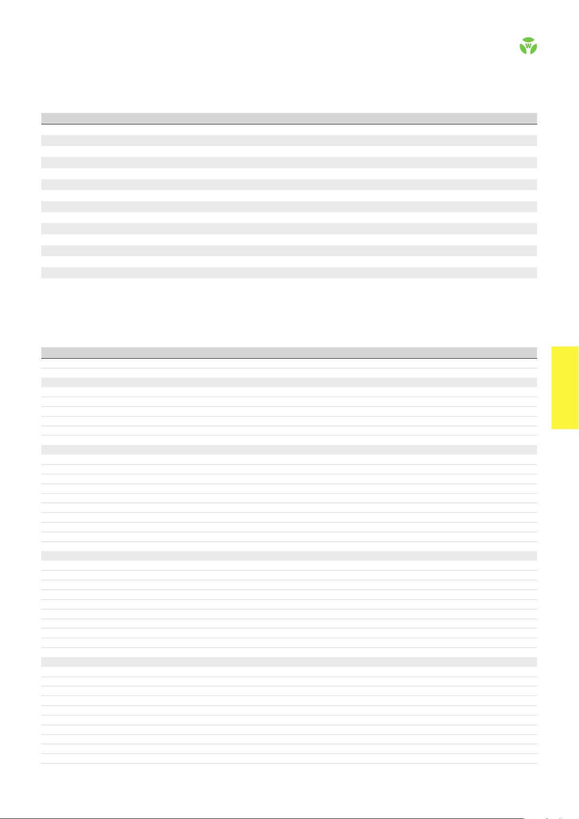
CIRCUIT DIAGRAM
• Automatic start – Reset input S34 is connected to safety input
S11. To monitor external contact blocks (EDM), their NC contacts
must be connected in series between S34 and S11.
• Manual start without monitoring – Reset input S34 is connected to safety input S11 via a RESET button. To monitor external
contact blocks (EDM), their NC contacts must be connected to the
RESET button in series.
• Monitoring of light curtains – The KM device types are especially suitable for the monitoring of very fast tactile switching
operations, for example in safety light curtain applications. Very
short switch-off procedures of a few milliseconds are detected
reliably and lead to the switching off of the internal relays.
SNA 4044K/KMSNA 4043K/KM SNA 4043KE
.
44
safe RE LAY
Page 2
OVERVIEW OF DEVICES | PART NUMBERS
Typ e Rated voltage Termi nal s Part no. P.U .
SNA 4043K-A 24 V AC/DC R1.188.1810.0 1
SNA 4043K-A 115-120 V AC R1.188.1830.0 1
SNA 4043K-A 230 V AC R1.188.1840.0 1
SNA 4043K-C 24 V AC/DC R1.188.1940.0 1
SNA 4043KM-A 24 V AC/DC R1.188.3250.0 1
SNA 4043KM-C 24 V AC/DC R1.188.3400.0 1
SNA 40 43KE-A AC/DC 24 V R1.188.3810.0 1
SNA 40 43KE-C AC/DC 24 V R1.188.3820.0 1
SNA 4044K-A 24 V AC/DC R1.188.1860.0 1
SNA 4044K-A 115-120 V AC R1.188.1880.0 1
SNA 4044K-A 230 V AC R1.188.1890.0 1
SNA 4044K-C 24 V AC/DC R1.188.1960.0 1
SNA 4044KM-A 24 V AC/DC R1.188.1480.0 1
SNA 4044KM-C 24 V AC/DC R1.188.3410.0 1
TECHNICAL DATA
Function Emergency stop relay
Function display 3 LEDs, green
Power supply circuit
Rated voltage U
N
A1, A2 24 V AC/DC / 42-48 V AC / 115 -120 V AC/ 230 V AC
Rated consumption 24 V DC / 24 V AC 1.6 W / 2.9 VA
42-48 V AC / 115-120 V AC / 230 V AC 2.3 W / 2.6 VA
Rated frequency 50 - 60 Hz
Operating voltage range U
B
Electrical isolation supply circuit - control circuit yes (at UN = 42-48 V AC, 115-230 V AC, 230 V AC)
Control circuit
Rated output voltage S11/S21 24 V DC
Input current / peak current S12, S52/S22 | S34 25 mA / 100 mA | 5 mA / 50 mA
Response time t
Minimum ON time t
Recover y time t
Release time t
Synchronous time t
Permissable test pulse time t
Max. resistivity, per channel
Output circuit
/ t
A1
A2
M
W
R
S
TP
1)
SNA 4043K/KM SNA 4044K/KM
Enabling paths 13/14, 23/24, 33/34 13/14, 23/24, 33/34, 43/44 normally open contact
Signaling paths 41/42 --- normally closed contact
Contact assignment forcebly guided
Contact type Ag-alloy, gold-plated
Rated switching voltage enabling / signaling path 230 V AC
Max. thermal current I
th
enabling / signaling path 8 A / 5 A
Max. total current I² of all current path (Tu = 55 ºC) / (Tu = 65 ºC) 25 A² / 9 A²
Application category (NO) AC-15 | DC-1 3 U
Short-circuit protection (NO), lead fuse / circuit breaker 6 A class gG / melting integral < 100 A²s
Mechanical life 10
General data
Creepage distances and clearances between the circuits EN 60 664 -1
Protection degree according to EN 60529 (housing / terminals) IP40 / IP20
Ambient temperature / storage temperature -25 ºC - +65 º C / -25 ºC - + 75 ºC
Wire ranges screw terminals, fine-stranded / solid 1 x 0.2 mm² – 2.5 mm² / 2 x 0.2 mm² – 1.0 mm²
fine-stranded with ferrules 1 x 0.25 mm² – 2.5 mm² / 2 x 0.25 mm² – 1.0 mm²
Permissible torque 0.5 - 0.6 Nm
Wire ranges push-in terminals 1 x 0.25 mm² – 1.5 mm²
Weight 24 V AC/DC device / AC device 0.21 kg / 0.25 kg
Standards EN ISO 13849-1, EN 62061, EN 81-20/50, EN 50156-1, EN 61511
Approvals TÜV, cULus, CCC, GL
1)
If two-channel devices are installed as single channel, the value is halved.
Screw terminals, pluggable
Screw terminals, pluggable
Screw terminals, pluggable
Push-in terminals, pluggable
Screw terminals, pluggable
Push-in terminals, pluggable
Screw terminals, pluggable
Push-in terminals, pluggable
Screw terminals, pluggable
Screw terminals, pluggable
Screw terminals, pluggable
Push-in terminals, pluggable
Screw terminals, pluggable
Push-in terminals, pluggable
0.85 - 1.1 x U
N
350 ms / 350 ms
100 ms
750 ms
10 ms
no
< 1 ms
24V AC/DC ≤ (5 + (1.176 x UB / UN - 1) x 100) Ω
42-48V AC/ 115-120 V AC, 230 V AC
≤ (5 + (1.176 x UB / UN - 1) x 100) Ω
230 V, Ie 3 A | Ue 24 V, Ie 3 A
e
7
switching cycles
safe REL AY
safe RE LAY
.
45
 Loading...