

Page 1
NOT FOR NEW DESIGNS
interface
NIB
Non-Incendive Barriers
interface
• Provides non-incendive isolation
for analog signals
• Eliminates need for explosion
proof enclosures
• Eliminates costly wiring
• DIN rail mountable housing
• CSA Approved
MODEL
Type
Wire Size
Max Voltage Output
Max Amperage Output
Width
Approvals
ANIB
Mechanical
Housing Material
Degree of Protection
Temperature Range
Wire Gauge
Tempature Code
Electrical
Nominal Input Voltage
Input Voltage Range
Maximum Input Voltage
Maximum Output Voltage
Nominal Input Current
Maximum Input Current
Nominal Output Current
Maximum Output Current
WT-NIC-24VDC/4-20mA - FU
Analog NIB
24-12 AWG
35 VDC
35 mA
20 mm
Part Number
Model Number
34.243.0010.0 1
Self-extinguishing polyamide
IP20
-40oC to +85oC
24 - 12 AWG
T3C (160°C)
24 VDC
5 - 30 VDC
35 VDC
35 VDC
4 - 20 mA
25 mA
4 - 20 mA
25 mA
Std.
Pack
Part Number
Model Number
Std.
Pack
Part Number
Model Number
Std.
Pack
Part Number
Model Number
Std.
Pack
Loop Resistance
CSA Hazardous Location
Installation
252 ohms at 4 mA, (1.01 Vd)
187 ohms at 20 mA, (3.75 Vd)
Class I, Division 2,
Groups A,B,C & D
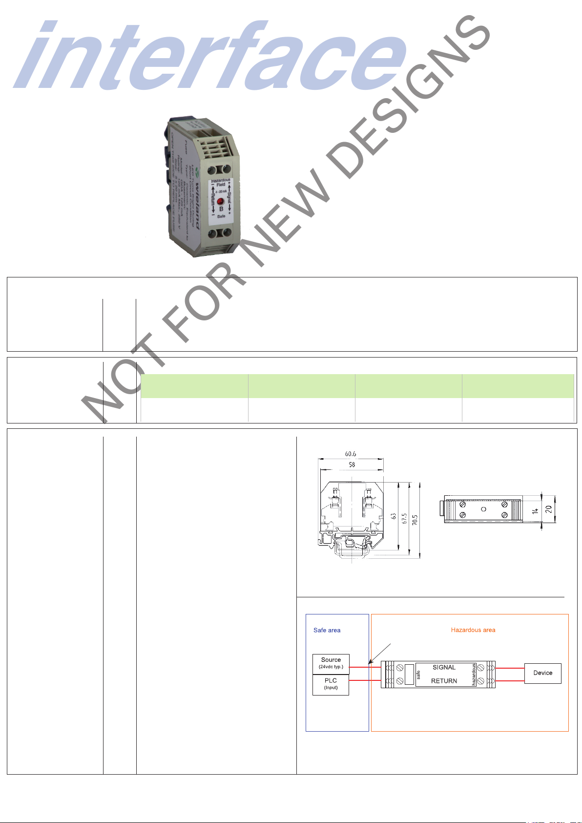
This device is designed to provide an electrical barrier
between control devices and hazardous location devices.
This is a non-fused device, a failure may cause it to fail in
a shorted state.
Must be installed in a suitable enclosure.
Return line must be referenced to 0V, the PLC input must
have a low resistance path the 0V. This is essential to the
proper operation of the barrier in over voltage situations.
If a low impedance to 0V cannot be guaranteed on
the return path, Wieland recommends the use of two
barriers (one per signal) and to connect one of the return
terminals on each barrier directly to ground
PLC input must have low
resistance to ground.
Wiring must be suitable for the
area. The input is not protected by
the barrier
Subject to change without notice
www.wieland-electric.ca
 Loading...