

Page 1

Section K Index
K1
General Information/Sizing .............K2-K3
MTAB Assembly ....................................K4
Advantage Series “NEMA Type 3R”
Air Conditioners
2000 BTU “RP17” Series,
Side Mount, N3R.....................................K6
3000 BTU “RP28” Series,
Side Mount, N3R.....................................K7
4000 BTU “RP33” Series,
Side Mount, N3R.....................................K8
6000 BTU “RP36” Series,
Side Mount, N3R.....................................K9
8000 BTU “RP47” Series,
Side Mount, N3R...................................K10
12000 BTU “RP47” Series,
Side Mount, N3R...................................K10
TrimLine Series “NEMA Type 12”
Air Conditioners
2000 BTU “NP17” Series,
Side Mount, N12 ...................................K12
4000 BTU “NP28” Series,
Side Mount, N12 ...................................K13
4000 BTU “NP33” Series,
Side Mount, N12 ...................................K14
ENVIRONMENTAL CONTROL
4000 BTU “NP36” Series,
Side Mount, N12 ...................................K15
6000 BTU “NP36” Series,
Side Mount, N12 ...................................K15
7000 BTU “NP47” Series,
Side Mount, N12 ...................................K16
10000 BTU “NP47” Series,
Side Mount, N12 ...................................K16
13000 BTU “NP47” Series,
Side Mount, N12 ...................................K16
Micro-Mini Series “NEMA Type 12”
Air Conditioners
1000 BTU Micro Series,
Side Mount, N12 ...................................K17
Integrity Series “NEMA Type 4X”
Air Conditioners
4000 BTU “32 Series”,
Side Mount, N4X ...................................K19
7000 BTU “38 Series”,
Side Mount, N4X.................................. K20
10000 BTU “47 Series”,
Side Mount, N4X ...................................K20
Compact Top Mount Series, “NEMA
TYPE 12” Air Conditioners
4000 BTU “Top Mount Series”, N12... K21
Vortex Coolers.....................................K22
WPFB/WPFBE Series
Filtered Box Fans & Grilles...............K24/25
WAAXFN/WAGARD Series
Muffin Fans & Finger Guards ................K26
WAVK/WAFLT Series
Louver Plate & Filter Kits.......................K27
EHG Series Radiant Heaters ................K29
WHVL Series Fan Heaters....................K30
WCR Series Fan Heaters .....................K31
EGL Series Fan Heaters.......................K32
ETR/ETF/ZR Series Thermostats ....K33/34
WAFMP Series
Fan Mounting Plate ...............................K36
1800 Filtered Fan Series
Filter Fan/Exhaust Filter/Mats ...........K37/38
WPF Series Filterfans™...................K39/40
WPFA Series Exhaust Grille & Filter .....K41
WPFG/WPFM/WPG Series
Gaskets, Mats & Grilles ........................K42
www.hubbell-wiegmann.com
Data Subject To Change Without Notice
Page 2

K2
ENVIRONMENTAL CONTROLS
GENERAL INFORMATION
Wiegmann has always recognized
that our customers in the electrical
and electronic marketplace need reliable, high quality enclosures and
environmental control products to
meet their protection requirements.
Protection Requirements today not
only mandate NEMA TYPE 12, 3R, 4,
& 4X, but also require a broad mix of
BTU & size selections. Wiegmann is
proud to offer those choices via a
whole new line of A/C products. They
are: Advantage Series, Trim Line
Series, Micro-Mini Series, Integrity
Series, and the Top Mount Series.
Three Basic Cooling Methods
When selecting a cooling method
there are three types to consider.
1 Passive Ventilation — If there is
only a minimal heat gain in your
circumstance, use of louvers or
grilles with filters can be effective.
This method, however, usually provides less cooling effect than is
necessary with today’s components.
2 Forced Convection Air Cooling —
If the installation will be in a clean,
non-hazardous environment with
an acceptable ambient (outside the
enclosure) temperature range, a
simple forced-air cooling system
utilizing outside air is usually adequate. Combined with an air filter,
such devices generally meet the
heat removal needs of typical electronic equipment and many electrical applications (Fig. 1). Examples
of forced convection air cooling are
filtered fans, fan trays, and blowers
of various types.
FIGURE 1 — Forced Convection Method
Filter & Grille
Required
Ambient Air
with Heat
Load
3 Closed-Loop Cooling —Inharsh
environments involving high temperatures, wash-down requirements,
heavy particulate matter or the
presence of chemicals capable of
damaging components (NEMA 4 or
12 environments), ambient air must
be kept out of the enclosure. Closedloop cooling consists of two separate circulation systems. One system, sealed against the ambient air,
cools and recirculates the clean
cool air throughout the enclosure.
The second system uses ambient air
or water to remove and discharge
the heat. Examples of closed-loop
cooling equipment employed with
electronics and process controls
are heat exchangers and air
conditioners.
Fan or Blower
with filter &
grille
Ambient
Air with
Heat Load
Ambient
Air
Fan or
Blower with
filter & grille
Pressurized System — pushes air through enclosure
Fans and Blowers can be used to pressurize (preferred) or exhaust cabinet air.
The ambient air should be filtered before it enters the cabinet.
Heated
Air
Cooled Air
In an air-to-air heat exchanger, heat from air surrounding the
electronics is removed by a specially designed heat transfer
element before being routed back into the enclosure.
Cabinet
FIGURE 2 - Closed Loop Cooling Method
Blower
Ambient Air
with Heat
Load
Ambient Air
Heat Exchanger
Blower
Ambient Air
Filter & Grille
Required
Cabinet
Exhaust System — pulls air through enclosure
Condenser
Heated
Air
Chilled
Air
In air conditioners, a condenser, an evaporator, and two blowers combine to chill the air circulating in the enclosure.
Ambient Air
with Heat
Load
Ambient Air
Blowers
Evaporator
www.hubbell-wiegmann.com
Data Subject To Change Without Notice
Page 3

ENVIRONMENTAL CONTROLS
AIR CONDITIONERS-APPLICATION INFORMATION
K3
Cooling Control Cabinets
Most electrical & electronic control
systems generate a substantial
amount of heat during operation. This
heat factor is intensified as controls
are made more compact, perform
more functions, and are placed in more
confined areas. Additional problems
are encountered when the electronic
process control system is located onsite in an industrial setting, rather than
in a clean computer room. The factory
environment can be hostile to the
point that performance and effective
life of the electronic components are
materially reduced, or the control system fails completely. Ambient temperature might be excessively high, as
that found in a steel mill. Moistureladen air and air-borne particulate
matter might be present to adversely
affect the electronic components, as
in the paper manufacturing industry.
Air conditioners are designed to perform
reliably under many of these harsh
conditions and to provide the cooling
and environmental protection required
by sensitive electronic production
control systems.
Factors Affecting Model Selection
This selection is presented as a basic
outline or checklist of the various
conditions to be considered when
choosing a cooling unit for a certain
application. The following are factors
which must be considered when
selecting a cooling unit:
Internal Heat Load — This is the heat
dissipated by the electronic controls.
It is expressed in watts. One watt
equals 3.413 BTU/HR. Thus, to obtain
the approximate cooling capacity
required to remove a specific heat load,
the following formula can be used:
Watts x 3.413 = BTU/HR
For example, a heat load of 800 watts
requires an air conditioner capable of
removing at least 2,730 BTU/HR.
Resistance to Air Flow in the
Enclosure
Air Flow is measured in cubic feet per
minute (CFM). To create an air flow of
any desired velocity requires that
pressure be produced by the blower
in the air conditioner. Resistance to this
blower-produced air flow is created by
obstruction within the cabinet in the
air flow path. The resistance itself is
called pressure drop (P.D.) and is
measured in inches of water column.
The effect of significant restrictions in
the cabinet air flow path are as follows:
The obstructions cause pressure drops,
which leads to cool air flow reduction.
This reduction in cool air flow will
decrease the effective capacity of the
cooling unit. When selecting the
proper cooling unit, allowance must
be made for pressure drop.
Heat Load From The Surroundings
Ambient conditions can cause a heat
gain in the enclosure. The rated
capacity of the cooling unit must be
sufficient to handle this heat gain.
When evaluating the additional heat
load gained from the surroundings,
the subject more or less breaks down
into two situations: (1) the cabinet is
insulated and well sealed, or (2) the
cabinet is not insulated (most cabinets
are uninsulated.)
(1) Cabinet Insulated — Normally, well
insulated cabinets will not gain sufficient ambient heat to affect air conditioner’s operation. Maximum operating
temperature for our air conditioners is
125°F. When the air conditioner operaties in ambient temperatures below
125°F, the cooling capacity of the air
conditioner substantially increases.
(2) Cabinet Not Insulated —
Obviously, this design placed more of
a burden on the cooling unit. Heat is
conducted to the cool side. Thus,
high ambient heat will be readily
transmitted into the cooler enclosure.
To determine the additional capacity
required of our air conditioner installed
in an uninsulated cabinet, the surface
square footage of the enclosure must be
Cooling And Control Cabinets
STEP ONE
1 Watt = 3.413 BTU/HR.
Determine the internal
heat load in Watts that
must be dissipated.
STEP TWO
1 m2 = 10.76 ft.2
Calculate the exposed
surface area of the
enclosure: 2(h’ x w’) +
2(h’ x d’) + (w’ x d’) =
Area (ft2)
calculated to obtain the total effective
heat transfer area. For this calculation, use the surface area of the
sides, plus the area of the top, and
omit the bottom area of the cabinet.
Air movement outside the uninsulated
cabinet will increase the heat conducted from the ambient into the enclosure.
When there is little or no air circulation
outside the cabinet, the layer of air
immediately adjacent to the exterior
cabinet walls acts as an insulating
film. Exterior air movement dissipates
this insulating layer of air in proportion
to the velocity of the air flow. Substantial
am-bient air circulation will increase
the transmitted heat load imposed on
the cooling unit.
If the cabinet being cooled is not air
tight, then high ambient relative humidity
will adversely affect the cooling effectiveness of the air conditioner. When
humid air infiltrates a poorly sealed
enclosure, the air conditioner is required
to use up valuable BTU/HR capacity
just to condense the moisture from the
internal air. Conversely, if the cabinet
is well sealed, high ambient relative
humidity, has very little effect on the
heat capacity of the air conditioner.
Steps For Sizing an Air Conditioner
Proper selection of an air conditioner
is determined by the following criteria:
• Required cooling capacity BTU/hr.
(complete Steps #1-4)
• Mounting requirements (top or side
mounting options)
• Dimension of air conditioner and
enclosure
STEP THREE
1oC or 1oKΔT=1.8oF T
Determine the temperature differential by subtracting the maximum
allowable temperature
inside the enclosure
(Ti) from the maximum
ambient temperature
outside the enclosure
(To) To-Ti=ΔT
STEP FOUR
(Watts x 3.413) +
[1.25 x Area ft.2 x
ΔT(°F)]
=BTU/HR.
Capacity
Required BTU/HR.
Capacity Rating
www.hubbell-wiegmann.com
Data Subject To Change Without Notice
Page 4

K4
ENVIRONMENTAL CONTROLS
M/TAB MOUNTING TEMPLATE AND ASSEMBLY
FEATURES-SPECIFICATIONS
Description
highlight of the Panel-Mounted
A
TrimLine Series is an easy, revolutionary
system for installing Panel-Mounted
Air Conditioners and Heat Exchangers
onto electronic or electrical enclosures.
The M/TAB is standard on all TrimLine
Air Conditioners. This integral system
functions as a mounting template,
pre-installation hanger and final
assembly bracket.
The M/TAB was specifically designed
to assist in the difficult job of installing
enclosure Air Conditioners. It simplifies
the installation process by eliminating
the problem of handling flangemounted Air Conditioners. The solution is provided by following these
installation steps...
• Use the M/TAB as a template to
drill holes for mounting to the
enclosure
• Bolt M/TAB to enclosure
• Cut out the Supply and Return
openings
• Hang the Air Conditioner or Heat
Exchanger on the M/TAB
• Secure the unit to the M/TAB
The M/TAB also allows for the quick
removal and transportation of the Air
Conditioner or Heat Exchanger, separate from the equipment, for servicing
or change to a different capacity
same-size Air Conditioner or to a
same-size Heat Exchanger.
Features
• No exposed rails or mounting
flanges; aesthetically pleasing
while conserving cabinet space
• Reduction in installation time and
labor, with significant cost savings
• Ease of installation and one piece
design reduce mounting errors
• Allows the installer to operate independently
• Functions as a pre-installation
hanger and final assembly bracket
• Installation is totally outside the
enclosure; no clumsy mounting
from inside the enclosure
www.hubbell-wiegmann.com
Data Subject To Change Without Notice
DATA SUBJECT TO CHANGE WITHOUT NOTICE
Page 5

ENVIRONMENTAL CONTROLS
INDOOR/OUTDOOR SIDE-MOUNTED AIR CONDITIONERS
FEATURES-SPECIFICATIONS
K5
NEMA
TYPE 3R & 12
MAINTAINED
Description
At last - air conditioners designed
specifically for cooling electronic
enclosures that can be used for both
indoor and outdoor applications right
out of the box!
No more bulky unattractive weatherhoods... No more worries over what
options to specify for outdoor
applications.
Expertly designed and crafted, the
ADVANTAGE Series boasts a stylish
appearance with rounded edges, no
visible hardware and a textured
baked powder finish to blend easily
with contemporary enclosure designs.
Serviceability has been made easier
by incorporating a “knock-down”
sheetmetal design which provides
quick access to internal components.
These air conditioners are available
in capcities from 2,000 to 22,000
BTU/H in seven heights, all utilizing
the exclusive M/TAB integral mounting system.
Features
• Capacities: 2,000 to 22,000 BTU/H
• Textured Beige Powder Finish
• Built-in Condensate Evaporator
• CFC-Free Refrigerant
• Closed-Loop Cooling
• Crankcase Compressor Heater
• Digital Temperature Display
• EMI/RFI Suppressor
• Head Pressure Control Switch
• Heavy-duty Steel Enclosure
• Low Temperature Control
Thermostat
• M/TAB Mounting System
• NEMA 3R and 12 Ratings
Maintained (UL50)
• Filters
• Six Foot [1.8m] (minimum) SJT
3-wire Cord
• UL/CUL Recognized
• Completelineofaccessories
RP17
2,000 BTU/H
17"H x 12"W x 11"D
RP28
3,000 BTU/H
28"H x 12"W x 11"D
RP33
4,000 BTU/H
33"H x 12"W x 11"D
RP36
6,000 BTU/H
36"H x 15"W x 11"D
RP47
8,000 & 12,000
BTU/H
47"H x 15"W x 13"D
www.hubbell-wiegmann.com
Data Subject To Change Without Notice
RP52
18,000 BTU/H
52"H x 17"W x 16"D
DATA SUBJECT TO CHANGE WITHOUT NOTICE
RP55
22,000 BTU/H
55"H x 22"W x 17"D
Page 6

K6
ENVIRONMENTAL CONTROLS
ADVANTAGE “RP17” SERIES AIR-COOLED
SIDE-MOUNTED AIR CONDITIONERS
12.35
[313.7]
2
NEMA
TYPE 3R & 12
MAINTAINED
FEATURES-SPECIFICATIONS
Standard Features
• Condensate Evaporator
• CFC-Free Refrigerant
• Crankcase Compressor Heater
• Digital Temperature Display
• EMI/RFI Suppressor
• Head Pressure Control Switch
• Filters
• Low Temperature Control Thermostat
• M/TAB Mounting System
• NEMA 3R & 12 Rating Maintained
• UL/CUL Recognized
‡
• Textured Beige Powder Finish
Accessories and Options
•
Cooling Effect Detector
• Enclosure Heater
• Filter Recoating Adhesive
• Filters for replacement
• Internal corrosion protection
• Painted Metal Grille
• Power Loss Delayed
Compressor Start
• Short Cycle Protector
• Special paint finishes
3
4
17 .50
[444.5]
PERFORMANCE CHART
WA4C2RP17R
4000
3500
3000
2500
2000
1500
1000
500
Cooling Capacity (BTU/H)
0
70
Operation within shaded area not
Operation within shaded area not
recommended.
recommended.
KA4C2RP17R
Maximum enclosure
air temperature ºF
80
90 100 110 120 130
Ambient Temperature (ºF)
17 .14
[435.4]
1
10.94
[277.8]
12 5
120
110
10 0
90
75
80
ADVANTAGE SERIES RP17 ADVANTAGE AIR-COOLED PANEL-MOUNTED AIR CONDITIONERS
MODEL
RATED CAPACITY 95/95 RATING AMBIENT TEMP. °F VOLTS HZ RUNNING APPROX.
(BTU/H) (BTU/H) MAX./MIN. AMPS WEIGHT (LBS.)
WA4C2RP17R 2000 1200 120/50 115/100 60/50 7.0/7.5 64
W2A4C2RP17R 2000 1200 120/50 230/200 60/50 4.0 64
(6) .281 [7.0]
1.05
[26.7]
2.20
[55.9]
6.75
71.5]
[1
6.75
[171.5]
Dimensions, inches [metric], are for reference only and subject to change.
‡
UL/CUL Recognized models are available as Listed at added cost.
DIA. HOLES
10.25
[260.4]
3
4
9.31
[236.5]
7.00
[177.8]
6.25
[158.8]
1.53
[38.9]
2.06
[52.3]
[12.7]
0.50
17 .50
[444.5]
10.94
[277.9]
1.00 [25.4] DIA. HOLE
9.54
[242.3]
7.60
[193.0]
1.56
[39.6]
2
12.35
[313.7]
1
[1
6.18
57.0]
2.21
[56.1]
MOUNTING PLAN
1.00
[25.4]
1.06
[27.0]
6.75
[171.5]
15.13
[384.2]
6.75
[171.5]
0.56
[14.3]
9.31
[236.5]
3
4
10.25
[260.4]
11.25
[285.8]
7.00
[177.8]
6.25
[158.8]
(6) .281 [7.0]
DIA. HOLES
0.44
[11.4]
www.hubbell-wiegmann.com
Data Subject To Change Without Notice
DATA SUBJECT TO CHANGE WITHOUT NOTICE
Page 7

ENVIRONMENTAL CONTROLS
ADVANTAGE “RP28” SERIES AIR-COOLED
SIDE-MOUNTED AIR CONDITIONERS
12.35
[313.7]
K7
FEATURES-SPECIFICATIONS
Standard Features
• Condensate Evaporator
• CFC-Free Refrigerant
• Crankcase Compressor Heater
• Digital Temperature Display
• EMI/RFI Suppressor
• Head Pressure Control Switch
• Filters
• Low Temperature Control Thermostat
• M/TAB Mounting System
• NEMA 3R & 12 Rating Maintained
• UL/CUL Recognized
‡
• Textured Beige Powder Finish
NEMA
TYPE 3R & 12
MAINTAINED
Accessories and Options
• Cooling Effect Detector
• Enclosure Heater
• Filter Recoating Adhesive
• Filters for replacement
• Internal corrosion protection
• Painted Metal Grille
• Power Loss Delayed Compressor
Start
• Short Cycle Protector
• Special paint finishes
27.75
[704.9]
4
3
PERFORMANCE CHART
WA4C3RP28R
6000
5250
4500
3750
3000
2250
1500
750
Cooling Capacity (BTU/H)
0
70
KA4C3RP28R
Maximum enclosure
air temperature ºF
80
90 100 110 120 130
Ambient Temperature (ºF)
Operation within shaded area not
recommended.
27.39
[695.6]
2
1
10.94
[277.8]
125
120
110
10 0
90
80
75
ADVANTAGE SERIES RP17 ADVANTAGE AIR-COOLED PANEL-MOUNTED AIR CONDITIONERS
MODEL
RATED CAPACITY 95/95 RATING AMBIENT TEMP. °F VOLTS HZ RUNNING APPROX.
(BTU/H) (BTU/H) MAX./MIN. AMPS WEIGHT (LBS.)
WA4C3RP28R 3000 2220 125/50 115/100 60/50 9.8/9.7 86
W2A4C3RP28R 3000 2220 115/50 230/200 60/50 5.5/5.6 86
1.91
[48.5]
8.00
[203.2]
TYP.
1. 1 8
[29.9]
9.00
[228.6]
4
3
10.00
[254.0]
1.67
[42.4]
[165.1]
12.88
[327.2]
5.00
[127.0]
6.50
1.78
[45.2]
27.75
[704.8]
10.94
[277.8]
10.17
[258.3]
8.64
[219.4]
8.59
[217.9]
1.50
[38.1]
6.21
[157.7]
2
12.35
[313.6]
1.00 [25.4] DIA. HOLE
MOUNTING PLAN
1.68
[42.7]
8.00
[203.2]
TYP.
27.75
[704.9]
1.84
[46.7]
1. 1 8
[30.0]
9.00
[228.6]
4
3
10.00
[254.0]
12.35
[313.7]
Dimensions, inches [metric], are for reference only and subject to change.
‡
UL/CUL Recognized models are available as Listed at added cost.
2.51
[63.7]
1
UNIT MUST BE 4" [100mm]
MINIMUM ABOVE FLOOR
FOR FILTER ACCESS
(8) .281 [7.0]
DIA. HOLES
6.50
[165.1]
12.88
[327.2]
5.00
[127.0]
1.78
[45.2]
www.hubbell-wiegmann.com
Data Subject To Change Without Notice
DATA SUBJECT TO CHANGE WITHOUT NOTICE
Page 8

K8
ENVIRONMENTAL CONTROLS
ADVANTAGE “RP33” SERIES AIR-COOLED
SIDE MOUNT AIR CONDITIONERS
12.35
[313.7]
NEMA
TYPE 3R & 12
MAINTAINED
FEATURES-SPECIFICATIONS
Standard Features
• Built-in Condensate Evaporator
• CFC-Free Refrigerant
• Crankcase Compressor Heater
• Digital Temperature Display
• EMI/RFI Suppressor
• Head Pressure Control Switch
• Filters
• Low Temperature Control Thermostat
• M/TAB Mounting System
• NEMA 3R & 12 Rating Maintained
• UL/CUL Recognized
‡
• Textured Beige Powder Finish
Accessories and Options
• Cooling Effect Detector
• Enclosure Heater
• Filter Recoating Adhesive
• Filters for replacement
• Internal corrosion protection
• Painted Metal Grille
• Power Loss Delayed Compressor
Start
• Short Cycle Protector
• Special paint finishes
32.75
[831.9]
4
3
PERFORMANCE CHART
WA4C4RP33R
9600
8400
7200
6000
4800
3600
2400
1200
Cooling Capacity (BTU/H)
0
70
KA4C4RP33R
Maximum enclosure
air temperature ºF
80
75
80
90 100 110 120 130
Ambient Temperature (ºF)
Operation within shaded area not
recommended.
32.39
[822.7]
2
1
10.94
[277.8]
12 5
120
110
90
100
WDTS SERIES ENVIRONMENTAL CONTROLS 3500 BTU SIDE MOUNT AIR CONDITIONERS
MODEL
RATED CAPACITY 95/95 RATING AMBIENT TEMP. °F VOLTS HZ RUNNING APPROX.
(BTU/H) (BTU/H) MAX./MIN. AMPS WEIGHT (LBS.)
WA4C4RP33R 4000 2850 125/50 115/100 60/50 13.6/13.3 98
W2A4C4RP33R 4000 2850 125/50 230/200 60/50 5.8 98
10.2 5
2.04
[51.8]
9.62
[244.3]
TYP.
(8) .281 [7.0]
DIA. HOLES
1. 8 4
[46.7]
1. 1 8
[30.0]
Dimensions, inches [metric], are for reference only and subject to change.
‡
UL/CUL Recognized models are available as Listed at added cost.
[260.4]
4
3
9.00
[228.6]
10.0 0
[254.0]
1. 0 5
[26.7]
4.00
[101.6]
16.5 0
[419.1]
7. 7 5
[196.9]
1. 6 8
[42.7]
2.72
[69.1]
1. 7 8
[45.2]
32.75
[831.9]
10.9 4
[277.9]
1.00 [25.4] DIA.HOLE
MOUNTING PLAN
13.3 5
[339.1]
8.54
[216.9]
10.5 0
[266.7]
1. 5 6
[39.6]
2
12.3 5
[313.7]
1
6.18
[157.0]
2.04
[51.8]
9.62
[244.3]
TYP.
(8) .281 [7.0]
DIA. HOLES
1. 8 4
[46.7]
[30.0]
2.43
[61.7]
10.2 5
[260.4]
4
3
9.00
[228.6]
1. 1 8
10.0 0
[254.0]
UNIT MUST BE 4" [100mm]
MINIMUM ABOVE FLOOR
FOR FILTER ACCESS
1. 0 5
[26.7]
4.00
[101.6]
16.5 0
[419.1]
7. 7 5
[196.9]
1. 6 8
[42.7]
2.72
[69.1]
1. 7 8
[45.2]
www.hubbell-wiegmann.com
Data Subject To Change Without Notice
DATA SUBJECT TO CHANGE WITHOUT NOTICE
Page 9

ENVIRONMENTAL CONTROLS
ADVANTAGE “RP36” SERIES AIR-COOLED
SIDE-MOUNTED AIR CONDITIONERS
15.3 5
[389.9]
K9
NEMA
TYPE 3R & 12
MAINTAINED
FEATURES-SPECIFICATIONS
Standard Features
• Built-in Condensate Evaporator
• CFC-Free Refrigerant
• Crankcase Compressor Heater
• Digital Temperature Display
• EMI/RFI Suppressor
• Head Pressure Control Switch
• Filters
• Low Temperature Control Thermostat
• M/TAB Mounting System
• NEMA 3R & 12 Rating Maintained
• UL/CUL Recognized
‡
• Textured Beige Powder Finish
Accessories and Options
• Cooling Effect Detector
• Enclosure Heater
• Filter Recoating Adhesive
• Filters for replacement
• Internal corrosion protection
• Painted Metal Grille
• Power Loss Delayed Compressor
Start
• Short Cycle Protector
• Special paint finishes
36.75
[955.5]
4
3
PERFORMANCE CHART
WA4C6RP36R
9600
8400
7200
6000
4800
3600
2400
1200
Cooling Capacity (BTU/H)
0
70
KA4C6RP36R
Maximum enclosure
air temperature ºF
80
90 100 110 120 130
Ambient Temperature (ºF)
Operation within shaded area not
recommended.
1
2
10.9 4
[277.8]
36.30
[922.0]
125
120
110
100
90
80
75
ADVANTAGE SERIES RP36 ADVANTAGE AIR-COOLED PANEL-MOUNTED AIR CONDITIONERS
MODEL
RATED CAPACITY 95/95 RATING AMBIENT TEMP. °F VOLTS HZ RUNNING APPROX.
(BTU/H) (BTU/H) MAX./MIN. AMPS WEIGHT (LBS.)
WA4C6RP36R 6000 4500 125/50 115/100 60/50 19.5/20.0 123
W2A4C6RP36R 6000 4500 115/50 230/200 60/50 19.5/20.0 123
MOUNTING PLAN
1. 1 0
[27.9]
(12) .281 [7.0]
DIA. HOLES
6.75
[171.5]
TYP.
5.75
[146.1]
1. 4 3
[36.3]
1.84
[46.7]
Dimensions, inches [metric], are for reference only and subject to change.
‡
UL/CUL Recognized models are available as Listed at added cost.
13.16
[334.3]
4
3
12.5 0
[317.5]
TYP.
7. 7 5
[196.9]
[124.0]
28.96
[735.6]
1. 8 4
[46.7]
4.88
36.75
[933.5]
13.2 5
[336.6]
36.30
[922.0]
1. 5 6
[39.6]
2
15.3 4
[389.6]
1
1. 1 0
[27.9]
(12) .281 [7.0]
DIA. HOLES
5.75
[146.1]
1. 4 3
[36.3]
1. 8 4
[46.7]
6.75
[171.5]
TYP.
UNIT MUST BE 4" [100mm]
MINIMUM ABOVE FLOOR
FOR FILTER ACCESS
13.16
[334.3]
4
3
12.5 0
[317.5]
TYP.
7. 7 5
[196.9]
[124.0]
28.96
[735.6]
1. 8 4
[46.7]
4.88
www.hubbell-wiegmann.com
Data Subject To Change Without Notice
DATA SUBJECT TO CHANGE WITHOUT NOTICE
Page 10

K10
ENVIRONMENTAL CONTROLS
ADVANTAGE “RP47” SERIES AIR-COOLED
SIDE-MOUNTED AIR CONDITIONERS
15.3 5
[389.9]
NEMA
TYPE 3R & 12
MAINTAINED
Standard Features
• Built-in Condensate Evaporator
• CFC-Free Refrigerant
• Crankcase Compressor Heater
• Digital Temperature Display
• EMI/RFI Suppressor
• Head Pressure Control Switch
• Filters
• Low Temperature Control Thermostat
• M/TAB Mounting System
• NEMA 3R & 12 Rating Maintained
• UL/CUL Recognized
‡
• Textured Beige Powder Finish
36.75
[955.5]
4
3
Accessories and Options
• Cooling Effect Detector
• Enclosure Heater
• Filter Recoating Adhesive
• Filters for replacement
• Internal corrosion protection
• Painted Metal Grille
• Power Loss Delayed Compressor
Start
• Short Cycle Protector
• Special paint finishes
36.30
[922.0]
PERFORMANCE CHART
2
16000
14000
12000
10000
1
10.9 4
[277.8]
8000
6000
4000
2000
Cooling Capacity (BTU/H)
16000
14000
12000
10000
8000
6000
4000
2000
Cooling Capacity (BTU/H)
0
70
0
70
WA4C8RP47R
KA4C8RP47R
Maximum enclosure
air temperature ºF
80
90 100 110 120 130
Ambient Temperature (ºF)
WA4C12RP47R
KA4C12RP47R
Maximum enclosure
air temperature ºF
80
90 100 110 120 130
Ambient Temperature (ºF)
12 5
120
110
100
125
120
110
100
90
80
75
90
80
75
Operation within shaded area not
recommended.
ADVANTAGE SERIES RP47 ADVANTAGE AIR-COOLED PANEL-MOUNTED AIR CONDITIONERS
MODEL
RATED CAPACITY 95/95 RATING AMBIENT TEMP. °F VOLTS HZ RUNNING APPROX.
(BTU/H) (BTU/H) MAX./MIN. AMPS WEIGHT (LBS.)
WA3C8RP47R 8000 6600 125/50 115/100 60/50 12.2/12.7 150
W2A3C8RP47R 8000 6600 125/50 230/200 60/50 5.7/5.9 150
WA3C12RP47R 12000 8500 125/50 115/100 60/50 19.8/19.1 150
W2A3C12RP47R 12000 8500 125/50 230/200 60/50 9.1/9.0 150
15.3 5
[389.9]
1. 4 3
[36.3]
(14) .281 [7.0]
DIA. HOLES
7. 0 0
[177.8]
TYP.
3.13
[79.5]
1. 1 0
[27.9]
Dimensions, inches [metric], are for reference only and subject to change.
‡
UL/CUL Recognized models are available as Listed at added cost.
12.5 0
[317.5]
4
3
12.5 0
[317.5]
13.16
[334.3]
7. 0 0
[177.8]
27.75
[704.9]
7. 7 5
[196.9]
47.25
[1200.2]
1. 8 4
[46.7]
(14) .281 [7.0]
DIA. HOLES
7. 0 0
[177.8]
TYP.
1. 4 3
[36.3]
3.13
[79.5]
1. 1 0
[27.9]
12.5 0
[317.5]
4
3
12.5 0
[317.5]
13.16
[334.3]
7. 0 0
[177.8]
27.75
[704.9]
7. 7 5
[196.9]
1. 8 4
[46.7]
47.25
[1200.2]
13.2 5
[336.6]
46.81
[1189.0]
UNIT MUST BE 4" [100mm]
MINIMUM ABOVE FLOOR
FOR FILTER ACCESS
15.3 5
[389.9]
2
1
www.hubbell-wiegmann.com
Data Subject To Change Without Notice
DATA SUBJECT TO CHANGE WITHOUT NOTICE
Page 11

FEATURES-SPECIFICATIONS
ENVIRONMENTAL CONTROLS
TRIMLINE SERIES AIR-COOLED
SIDE-MOUNTED AIR CONDITIONERS
NEMA
TYPE 12
MAINTAINED
K11
Description
Innovations in technology have resulted
in much denser components packaging and smaller available panel sizes
on which to mount Air Conditioners.
The TrimLine Series is the response to
these new packaging demands with
the Narrow 10", 12", 15" and 17" width
panel-mount air conditioners. In addition to being narrower than traditional
Air Conditioner units, the TrimLine
Series include the Condensate
Evaporator, Low Temperature Control
Thermostat and EMI/RFI Suppressor
as standard features and are available
in all popular voltages and frequencies.
The TrimLine Series consists of compact models in 2,000-2,500 BTU/H
capacities, mid-size models, 28", 33"
and 36" WITH up to 4,000, 5,000 and
6,000 BTU/H respectively and the fullsize model at 47" with 10,000 BTU/H.
Each model series is designed with a
minimum width to take up less cabinet
space on the exterior panel or door.
Integral to the TrimLine Series is the
M/TAB (Mounting Template and
Assembly Bracket) system which
makes installing Air Conditioners simple
and fast and interchangeable with corresponding TrimLine Heat Exchangers.
Outdoor or corrosive environments
require weather protection and/or
special internal and external protective features. For outdoor applications
see the Advantage and Integrity
Outdoor Series.
For extreme ambient temperatures
and/or severely contaminated environments, the use of TrimLine or other
Water-Cooled Air Conditioners are
recommended.
Features
• Capacities: 2,000 to 10,000 BTU/H;
six heights available
• CFC-free or Low ODP Refrigerant
• All models UL/CUL Listed or
Recognized
• Tested and approved by UL for
NEMA 12 Enclosures
• Compact design with slim 10",
12", 15" and 17" wide mounting
footprints
• Exclusive KOOLTRONIC M/TAB
integral mounting system for quick,
easy installation
• Built-in Condensate Evaporator
eliminates need for draining normal
condensate
• Thermostatic Low Temperature
Control prevents over-cooling and
provides energy-efficient operation
• EMI/RFI Suppressor minimizes transient line spikes during on/off cycling
• Field-reversible condenser outlet
blower provides choice of horizontal or vertical air discharge
• Heavy-duty steel enclosures with
gray baked powder finish
• Six foot (minimum) SJT 3-wire
power cord
• Complete line of accessories
NP17
2,000 BTU/H
17”H x 12”W x 9”D
Narrow-Mini
2,500 BTU/H
20”H x 10”W x 10”D
NP28
4,000 BTU/H
28”H x 11”W x 12”D
www.hubbell-wiegmann.com
Data Subject To Change Without Notice
NP33
4,000 BTU/H
33”H x 12”W x 9”D
NP36
4,000 & 6,000 BTU/H
36”H x 15”W x 12”D
DATA SUBJECT TO CHANGE WITHOUT NOTICE
7,000, 8,000,
10,000 12,000
47”H x 15”W x 12”D
NP47
BTU/H
Page 12

K12
ENVIRONMENTAL CONTROLS
TRIMLINE “NP17” SERIES
SIDE-MOUNTED AIR CONDITIONERS
Standard Features
• Built-in Condensate Evaporator
• CFC-Free Refrigerant
• EMI/RFI Suppressor
• Low Temperature Control Thermostat
• M/TAB Mounting System
• NEMA 12 Rating Maintained (UL50)
• UL/CUL Listed
• Gray Powder Finish
Accessories and Options
• Cooling Effect Detector
NEMA
TYPE 12
MAINTAINED
• Filter Recoating Adhesive
• Filters for replacement
• Internal corrosion protection
• Lifting Eyes
• Low Ambient Kit
• Short Cycle Protector
‡
• Special materials or finishes
• Special motors, line cords, or
connectors
• Stainless or Aluminum Cabinet
• Weather Protection Kit
M/TAB
12.25
[311.2]
THERMOSTAT
ADJUSTMENT
ACCESS
3
4
PERFORMANCE CHART
WA4C2.0NP17L
4000
3500
3000
2500
2000
1500
1000
500
Cooling Capacity (BTU/H)
0
70
KA4C2.0NP17L
Maximum enclosure
air temperature ºF
80
90 100 110 120 130
Ambient Temperature (ºF)
Operation within shaded area not
recommended.
12.13
[308.1]
1
17.50
[444.5]
2
9.00
[228.6]
125
120
110
100
90
75
80
TRIMLINE SERIES NP17 AIR-COOLED PANEL-MOUNTED AIR CONDITIONERS
MODEL
RATED CAPACITY 95/95 RATING AMBIENT TEMP. °F VOLTS HZ RUNNING APPROX.
(BTU/H) (BTU/H) MAX./MIN. AMPS WEIGHT (LBS.)
WA4C20NP17L 2000 1420 125/50 115/100 60/50 6.7/6.5 59
W2A4C20NP17L 2000 1420 125/50 230/200 60/50 4.3 59
MOUNTING PLAN
12.25
[311.2]
(6)1/4-20 WELD NUTS
3
M/TAB
6' [1.83M] MIN.
POWER CORD
4
Dimensions, inches [metric], are for reference only and subject to change.
‡
UL/CUL Recognized models are available as Listed at added cost.
9.00
[228.6]
2
0.38 [9.5] O.D.
CONDENSATE DRAIN
17.50
[444.5]
0.50
[12.7]
FILTER
0.50
[12.7]
TYP.
1
8.13
[206.5]
TYP.
0.38
12.13
[308.1]
Weld nuts supplied for alternate mounting method to
maintain NEMA 12. Mounting Plans furnished on request.
[9.5]
(8) .312 [7.9]
DIA HOLES
6.13
[155.7]
11.25
[285.8]
4
3
8
5.75
[146.1]
3
8
3.13
[79.5]
5.00
[127.0]
4.13
[104.9]
6.38
[162.1]
0.38
[9.5]
0.38
[9.5]
17.50
[444.5]
0.88
[22.4]
www.hubbell-wiegmann.com
Data Subject To Change Without Notice
DATA SUBJECT TO CHANGE WITHOUT NOTICE
Page 13

ENVIRONMENTAL CONTROLS
TRIMLINE “NP28” SERIES AIR-COOLED
SIDE-MOUNTED AIR CONDITIONERS
10.13
[257.3]
K13
NEMA
TYPE 12
MAINTAINED
Standard Features
• Built-in Condensate Evaporator
• CFC-Free Refrigerant
• EMI/RFI Suppressor
• Low Temperature Control
Thermostat
• M/TAB Mounting System
• NEMA 12 Rating Maintained (UL50)
• UL/CUL Listed
• Gray Powder Finish
Accessories and Options
• Cooling Effect Detector
• Filter Recoating Adhesive
• Filters for replacement
• Internal corrosion protection
• Lifting Eyes
• Low Ambient Kit
• Short Cycle Protector
• Special materials or finishes
• Special motors, line cords, or
connectors
• Stainless or Aluminum Cabinet
• Weather Protection Kit
M/TAB
2
28.50
[723.9]
THERMOSTAT
ADJUSTMENT
ACCESS
3
1
4
11.50
3
[292.1]
PERFORMANCE CHART
WA4C4NP28L
8000
7000
6000
5000
4000
3000
2000
1000
Cooling Capacity (BTU/H)
0
70
KA4C4NP28L
Maximum enclosure
air temperature ºF
80
90 100 110 120 130
Ambient Temperature (ºF)
75
125
120
110
100
90
80
Operation within shaded area not
recommended.
TRIMLINE SERIES NP28 AIR-COOLED PANEL-MOUNTED AIR CONDITIONERS
MODEL
RATED CAPACITY 95/95 RATING AMBIENT TEMP. °F VOLTS HZ RUNNING APPROX.
(BTU/H) (BTU/H) MAX./MIN. AMPS WEIGHT (LBS.)
WA4C4NP28L 4000 2520 125/50 115/100 60/50 13.0/12.0 85
W2A4C4NP28L 4000 2520 120/50 230/200 60/50 6.0 85
MOUNTING PLAN
6' [1.83M] MIN.
POWER CORD
M/TAB
11.50
[292.1]
CONDENSATE
DRAIN IN BOTTOM
1. 1 4
[28.9]
7.00
[177.8]
1.57
[39.8]
0.64
[16.2]
2
28.50
4
[723.9]
3
Dimensions, inches [metric], are for reference only and subject to change.
1
10.13
[257.3]
FILTER
3.41
[86.6]
7.75
[196.8]
4.19
[106.4]
2.76
[70.1]
7.75
[196.8]
1.50
[38.1]
3
4.30
[109.2]
4
3
7.00
[177.8]
8.00
[203.2]
2.92
[74.1]
1.07
[27.1]
7.50
[190.5]
TYP.
3.61
[91.6]
2.39
[60.7]
(8) .312 [7.9]
DIA. HOLES
www.hubbell-wiegmann.com
Data Subject To Change Without Notice
Page 14

K14
ENVIRONMENTAL CONTROLS
TRIMLINE “NP33” SERIES AIR-COOLED
SIDE-MOUNTED AIR CONDITIONERS
M/TAB
12.50
[317.5]
2
3
1
32.88
[835.2]
NEMA
TYPE 12
MAINTAINED
Standard Features
• Built-in Condensate Evaporator
• CFC-Free or Low ODP Refrigerant
• EMI/RFI Suppressor
• Low Temperature Control
Thermostat
• M/TAB Mounting System
• NEMA 12 Rating Maintained (UL50)
• Reversible Condenser Outlet Blower
• UL/CUL Listed
• Gray Powder Finish
Accessories and Options
• Cooling Effect Detector
• Enclosure Heater
• Filter Recoating Adhesive
• Filters for replacement
• Internal corrosion protection
• Lifting Eyes
• Low Airflow Detector
• Low Ambient Kit
• Short Cycle Protector
• Special materials or finishes
• Special motors, line cords, or
connectors
• Stainless or Aluminum Cabinet
• Weather Protection Kit
4
8000
7000
6000
5000
4000
3000
2000
1000
Cooling Capacity (BTU/H)
0
70
Operation within shaded area not
recommended.
9.50
[241.3]
PERFORMANCE CHART
WA4C4NP33L
KA4C4NP33L
Maximum enclosure
air temperature ºF
80
90 100 110 120 130
Ambient Temperature (ºF)
TRIMLINE SERIES NP33 AIR-COOLED PANEL-MOUNTED AIR CONDITIONERS
MODEL
RATED CAPACITY 95/95 RATING AMBIENT TEMP. °F VOLTS HZ RUNNING APPROX.
(BTU/H) (BTU/H) MAX./MIN. AMPS WEIGHT (LBS.)
WA4C4NP33L 4000 2680 125/50 115/100 60/50 12.8 90
W2A4C4NP33L 4000 2680 125/50 230/200 60/50 7.0 90
THERMOSTAT
ADJUSTMENT
ACCESS
75
125
120
110
100
90
80
1.05
[26.7]
[101.6]
16.50
[419.1]
[196.9]
[42.7]
2.04
[51.8]
9.62
[244.3]
TYP.
(8) .281 [7.0]
DIA. HOLES
1.84
[46.7]
[30.0]
1. 1 8
10.25
[260.4]
4
3
9.00
[228.6]
10.00
[254.0]
Dimensions, inches [metric], are for
reference only and subject to change.
4.00
7.75
1.68
2.72
[69.1]
1.78
[45.2]
32.75
[831.9]
13.35
[339.1]
10.94
[277.9]
1.00 [25.4] DIA.HOLE
8.54
[216.9]
10.50
[266.7]
1.56
[39.6]
2
12.35
[313.7]
1
6.18
[157.0]
(8) .281 [7.0]
DIA. HOLES
www.hubbell-wiegmann.com
Data Subject To Change Without Notice
2.04
[51.8]
2.43
[61.7]
MOUNTING PLAN
10.25
[260.4]
9.62
[244.3]
TYP.
1.84
[46.7]
[228.6]
1. 1 8
[30.0]
10.00
[254.0]
4
3
9.00
1.05
[26.7]
4.00
[101.6]
16.50
[419.1]
7.75
[196.9]
1.68
[42.7]
2.72
[69.1]
1.78
[45.2]
DATA SUBJECT TO CHANGE WITHOUT NOTICE
Page 15

NEMA
TYPE 12
MAINTAINED
ENVIRONMENTAL CONTROLS
TRIMLINE “NP36” SERIES AIR-COOLED
SIDE-MOUNTED AIR CONDITIONERS
15.19
[385.8]
2
PERFORMANCE CHARTS
WA4C4NP36L
8000
1
12.25
[311.2]
36.75
[933.5]
3
4
7000
6000
5000
4000
3000
2000
1000
Cooling Capacity (BTU/H)
0
70
KA4C4NP36L
80
90 100 110 120 130
Ambient Temperature (ºF)
K15
Maximum enclosure
air temperature ºF
125
120
110
100
90
80
75
Standard Features
• Built-in Condensate Evaporator
• CFC-Free Refrigerant
• EMI/RFI Suppressor
• Low Temperature Control Thermostat
• M/TAB Mounting System
• NEMA 12 Rating Maintained(UL50)
• Reversible Condenser Outlet Blower
• UL/CUL Listed/Recognized
‡
• Gray Powder Finish
Accessories and Options
• Cooling Effect Detector
• Filter Recoating Adhesive
• Filters for replacement
• Internal corrosion protection
• Lifting Eyes
• Low Ambient Kit
• Low Airflow Detector
• Short Cycle Protector
• Special materials or finishes
• Special motors, line cords, or
connectors
• Stainless or Aluminum Cabinet
• Weather Protection Kit
WA4C6NP36R
8000
7000
6000
5000
4000
3000
2000
1000
Cooling Capacity (BTU/H)
0
70
KA4C6NP36R
80
90 100 110 120 130
Ambient Temperature (ºF)
Operation within shaded area not
recommended.
TRIMLINE SERIES NP36 AIR-COOLED PANEL-MOUNTED AIR CONDITIONERS
MODEL
RATED CAPACITY 95/95 RATING AMBIENT TEMP. °F VOLTS HZ RUNNING APPROX.
(BTU/H) (BTU/H) MAX./MIN. AMPS WEIGHT (LBS.)
WA4C4NP36L 4000 3700 125/50 115/100 60/50 13.5 125
W2A4C4NP36L 4000 3700 125/50 230/200 60/50 7.5 125
WA4C6NP36R 6000 4100 125/50 115/100 60/50 16.5/17.0 125
W2A4C6NP36L 6000 4100 125/50 230/200 60/50 8.2 125
(OPTIONAL)
6' [1.82M] MIN.
POWER CORD
M/TAB
12.25
[311.2]
2
MOUNTING PLAN
1.50
[38.1]
[382.6]
[304.8]
15.06
12.00
2
36.75
[933.5]
3
4
CONDENSATE DRAIN
Dimensions, inches (metric), are for reference only and subject to change.
‡
UL/CUL Recognized models are available as Listed at added cost.
FILTER
1
15.19
[385.8]
THERMOSTAT
(10) .312 [7.9]
DIA. HOLES
6.75
[171.5]
TYP.
8.25
[209.6]
1.25
[31.8]
0.88
[22.2]
3
4
12.50
[317.5]
13.31
[338.1]
[304.8]
[492.1]
0.75
[19.1]
Maximum enclosure
air temperature ºF
125
120
110
100
90
80
75
12.00
36.75
[933.5]
19.38
3.00
[76.2]
www.hubbell-wiegmann.com
Data Subject To Change Without Notice
DATA SUBJECT TO CHANGE WITHOUT NOTICE
Page 16

ENVIRONMENTAL CONTROLS
K16
TRIMLINE “NP47” SERIES AIR-COOLED
SIDE-MOUNTED AIR CONDITIONERS
Standard Features
• Built-in Condensate Evaporator
• CFC-Free or Low ODP Refrigerant
• EMI/RFI Suppressor
• Low Temperature Control Thermostat
• M/TAB Mounting System
• NEMA 12 Rating Maintained (UL50)
• Reversible Condenser Outlet Blower
• UL/CUL Listed/Recognized
‡
• Gray Powder Finish
Accessories and Options
• Cooling Effect Detector
• Deep Drain Pan Kit
THERMOSTAT
ADJUSTMENT
ACCESS
3
NEMA
TYPE 12
MAINTAINED
4
• Enclosure Heater
• Filter Recoating Adhesive
• Filters for replacement
• Internal corrosion protection
• Lifting Eyes
• Low Airflow Detector
• Low Ambient Kit
• Short Cycle Protector
• Special materials or finishes
• Special motors, line cords, or
connectors
• Stainless or Aluminum Cabinet
• Weather Protection Kit
M/TAB
2
1
15.19
[385.8]
12.25
[311.2]
47.25
[1200.2]
PERFORMANCE CHARTS
WA4C7NP47L
12000
10500
9000
7500
6000
4500
3000
1500
Cooling Capacity (BTU/H)
13500
12000
10500
9000
7500
6000
4500
3000
Cooling Capacity (BTU/H)
1500
0
70
70
KA4C8NP47R
80
90 100 110 120 130
Ambient Temperature (ºF)
WA4C10NP47R
KA4C12NP47R
80
90 100 110 120 130
Ambient Temperature (ºF)
Operation within shaded area not
recommended.
Maximum enclosure
air temperature ºF
125
120
110
100
90
80
75
Maximum enclosure
air temperature ºF
125
120
110
100
90
80
75
TRIMLINE SERIES NP47 AIR-COOLED PANEL-MOUNTED AIR CONDITIONERS
MODEL
RATED CAPACITY 95/95 RATING AMBIENT TEMP. °F VOLTS HZ RUNNING APPROX.
(BTU/H) (BTU/H) MAX./MIN. AMPS WEIGHT (LBS.)
WA4C7NP47R 7000 4750 125/50 115/100 60/50 16.5 150
W2A4C7NP47L 7000 4750 125/50 230/200 60/50 8.6 150
WA3C10NP47R 10000 7250 120/50 115/100 60/50 19.2/18.6 160
W2A4C10NP47L 10000 7250 125/50 230/200 60/50 11.8 160
WA3C13NP47R 13000 7250 120/50 115/100 60/50 19.2/18.6 160
W2A4C13NP47R 13000 7250 125/50 230/200 60/50 11.8 160
MOUNTING PLAN
14.81
[376.2]
13.31
7.00
[177.8]
TYP.
0.88
[22.4]
1.50
[38.1]
10.13
[257.1]
1.25
[31.8]
[338.1]
12.00
[304.7]
4
12.50
[317.5]
3
Dimensions, inches [metric], are for
reference only and subject to change.
‡
UL/CUL Recognized models are
available as Listed at added cost.
FILTER
2
1
15.19
[385.8]
(OPTIONAL)
2
47.25
[1200.2]
12.25
[311.2]
OPTIONAL
CONDENSATE DRAIN
M/TAB
3
4
CONDENSATE
DRAIN
6' [1.82M] MIN.
POWER CORD
(12) .312 [7.9]
DIA. HOLES
0.75
[19.0]
18.00
[457.2]
23.88
[606.3]
3.00
[76.2]
46.63
[1184.4]
www.hubbell-wiegmann.com
Data Subject To Change Without Notice
DATA SUBJECT TO CHANGE WITHOUT NOTICE
Page 17

ENVIRONMENTAL CONTROLS
MICRO-MINI SERIES AIR-COOLED
SIDE-MOUNTED AIR CONDITIONERS
K17
FEATURES-SPECIFICATIONS
Standard Features
• Ball-bearing Motors
• CFC-Free Refrigerant
• EMI/RFI Suppressor
• Low Temperature Control Thermostat
• NEMA 12 Rating Maintained (UL50)
• UL/CUL Listed
• Gray Powder Finish
NEMA
TYPE 12
MAINTAINED
Accessories and Options
• Adapter Plate for rack mounting
• Compressor Heater
• Condensate Evaporator
• Cooling Effect Detector
• Filter Recoating Adhesive
• Filters for replacement
• Internal corrosion protection
• Lifting Eyes
THERMOSTAT
ADJUSTMENT
ACCESS
• Low Ambient Kit and Compressor
• Mounting Hinge
•ShortCycleProtector
• Special materials or finishes
• Special motors, line cords, or
• Stainless or Aluminum Cabinet
• Weather Protection Kit
14.13
[358.9]
Heater
connectors
13.25
[336.6]
6.25
[158.8]
12.88
[327.2]
MICRO-MINI SERIES AIR-COOLED PANEL-MOUNTED AIR CONDITIONERS
MODEL
RATED CAPACITY 95/95 RATING AMBIENT TEMP. °F VOLTS HZ RUNNING APPROX.
(BTU/H) (BTU/H) MAX./MIN. AMPS WEIGHT (LBS.)
WA4C10MML 1000 600 125/50 115/100 60/50 4.5 43
W2A4C10MML 1000 600 125/50 230/200 60/50 2.3 43
MOUNTING PLAN
14.13
13.6 3
[346.1]
4.44
[112.7]
2.75
[69.9]
9.81
[249.2]
4.44
[112.7]
DIA.
0.81
[20.6]
3.25
[82.6]
3
4
7. 9 4
[201.6]
3.25
[82.6]
1. 5 0
[38.1]
Dimensions, inches [metric], are for
reference only and subject to change.
(4) .281 [5.5]
DIA. HOLES
4.88
[123.8]
4.00
[101.6]
6.26
[158.8]
0.68
[17.3]
0.63
[15.9]
12.0 0
[304.8]
2
1
14.13
[358.8]
13.2 5
[336.6]
(4) .312 [8.0]
DIA. HOLES
12.8 8
[327.2]
OPTIONAL POWER
CORD EXIT
CONDENSATE
DRAIN
4.88
[123.8]
4.00
[101.6]
1. 5 0
[38.1]
1.50 [38.1] DIA.
POWERCORDHOLE
0.25
[6.4]
[358.8]
13.6 3
[346.1]
[112.7]
4.50
[114.3]
8.00
[203.2]
4.44
3
4
0.81
[20.6]
4.31
[109.5]
4.50
[114.3]
1. 0 0
[25.4]
2.75
[69.9]
12.8 8
[327.2]
1. 0 0
[25.4]
www.hubbell-wiegmann.com
Data Subject To Change Without Notice
Page 18

ENVIRONMENTAL CONTROLS
K18
FEATURES-SPECIFICATIONS
INTEGRITY SERIES NEMA4/4X AIR-COOLED
SIDE-MOUNTED AIR CONDITIONERS
NEMA
TYPE 4/4X
MAINTAINED
Description
Designed
and 4X Enclosure applications that
require washdown or are subject to
outdoor storm conditions, Integrity
NEMA 4/4X Air Conditioners protect
the ratings of NEMA 4 or 4X Enclosures.
These exclusive patented UL/CUL
Recognized Panel-Mounted Air
Conditioners provide superior closedloop cooling and also protect against
the hazards specified for both Indoor
and Outdoor NEMA 4 and 4X
Enclosures. Tested and rated by
universally recognized Underwriters
Laboratories, these uniquelydesigned 304-2B Stainless Steel Air
Conditioners prevent unwanted environmental penetration of NEMA 4 and
4X Enclosures as they provide a
clean, cool internal environment.
With the design advantages of the
Integrity NEMA 4/4X Series and the
inclusion of the unique Mounting
Template and Assembly Bracket
(M/TAB), modified for this design,
this series offers the finest in cooling
innovation and technology.
specifically for NEMA 4
Features
• Capacities range from 2,000 to
10,000 BTU/H in 32", 38", 47" and
59" heights
• UL/CUL Listed or Recognized
• Tested and approved by UL for
NEMA 4 and 4X Enclosures
• CFC-free Refrigerant
• Gasketed flanges on all four mount-
ing edges for positive leakproof seal
• Exclusive modified integral
Mounting Template and Assembly
Bracket (M/TAB) for quick, easy
installation.
©
• Thermostatic Low Temperature
Control prevents over-cooling and
provides energy-efficient operation
• Internal Corrosion Protection
• EMI/RFI Suppressor minimizes transient line spikes during on/off
cycling
• Separate blower-driven evaporator
and condenser air systems penetrate
high static pressure applications
• Rugged heavy duty stainless steel
exterior
www.hubbell-wiegmann.com
Data Subject To Change Without Notice
Page 19

ENVIRONMENTAL CONTROLS
INTEGRITY “32” SERIES AIR-COOLED
SIDE-MOUNTED AIR CONDITIONERS
13.12
[333.2]
K19
M/TA B
32.25
[819.2]
31.50
[800.1]
3
NEMA
TYPE 4/4X
MAINTAINED
4
3
14.50
[368.3]
2
1
13.00
[330.2]
PERFORMANCE CHART
Standard Features
• CFC-Free Refrigerant
• EMI/RFI Suppressor
• Internal corrosion protection
• Low Temperature Control Thermostat
• M/TAB Mounting System
• NEMA 4/4X Rating Maintained
(UL50)
• Stainless Steel Cabinet
• UL/CUL Recognized
‡
Accessories and Options
• Cooling Effect Detector
• Filter Recoating Adhesive
• Filters for replacement
• Lifting Eyes
• Low Ambient Kit & Compressor
Heater
• Short Cycle Protector
• Special materials or finishes
WNA4C4P32R
8000
7000
6000
5000
4000
3000
2000
1000
Cooling Capacity (BTU/H)
0
70
KNA4C4P32R
Maximum enclosure
air temperature ºF
80
90 100 110 120 1 30
Ambient Temperature (ºF)
Operation within shaded areas not
recommended.
INTEGRITY SERIES 32 AIR-COOLED PANEL-MOUNTED AIR CONDITIONERS
MODEL
RATED CAPACITY 95/95 RATING AMBIENT TEMP. °F VOLTS HZ RUNNING APPROX.
(BTU/H) (BTU/H) MAX./MIN. AMPS WEIGHT (LBS.)
WNA4C4P32L 4000 2650 125/50 115/100 60/50 13.0/12.0 105
W2NA4C4P32L 4000 2650 120/50 230/200 60/50 6.0 105
THERMOSTAT
ADJUSTMENT
ACCESS
125
120
110
100
90
80
75
MOUNTING PLAN
UNIT M/TAB & CUTOUTS
TYP.
10.5 0
[266.7]
TYP.
3
4
3
11.5 0
[292.1]
TYP.
1. 5 0
[38.1]
8.00
[20.3]
8.00
[20.3]
(6) .312 [8.0]
DIA. HOLES
2.18
[55.4]
2.18
[55.4]
3.81
[96.8]
(24) .203 [5.0]
DIA. HOLES
M/TA B
OUTLINE
14.5 0
1 .25
[31 .7]
4.00
[10 1.6]
4.25
[107.9]
TYP.
1 .37
[34.8]
0.37
[9.4]
Dimensions, inches [metric], are for reference only and subject to change.
‡
UL/CUL Recognized models are available as Listed at added cost.
[368.3]
4
13.7 5
[349.2]
(24) .250 [6.3]
DIA. HOLES
3
[31 .7]
31 .50
[800.1]
3
0.37
[9.4]
UNIT
OUTLINE
1. 2 5
4.62
[1 17.3]
2.00
[50.8]
[130.0]
3.50
[88.9]
5.12
13.0 0
[330.2]
www.hubbell-wiegmann.com
Data Subject To Change Without Notice
3.12
[79.2]
4.00
[101.6]
TYP.
POWER
CORD
26.00
[660.4]
12.88
[327.2]
5.00
[127.0]
4
30.19
[766.8]
3
0.88
[22.4]
0.81
[20.6]
UNIT MUST BE 12" (300mm)
MINIMUM ABOVE FLOOR
FOR FILTER ACCESS
[331.7]
M/TA B
13.06
32.25
[819.2]
14.50
[368.3]
13.13
[333.2]
13.75
[349.3]
1
1. 0 0
[25.4]
4.00
[101.6]
4.25
[108.0]
TYP.
1. 3 8
[35.1]
0.38
[9.7]
2
Page 20

ENVIRONMENTAL CONTROLS
K20
INTEGRITY SERIES 38 & 47 AIR-COOLED PANEL-MOUNTED AIR CONDITIONERS
MODEL
WNA4C7P38L 7000 6000 131/50 115/100 60/50 20 180
W2NA4C7P38L 7000 6000 131/50 230/200 60/50 9.3/9.9 180
W2NA4C10P47L 10000 7750 131/50 230/200 60/50 10.9/12.5 205
INTEGRITY “38 & 47” SERIES AIR-COOLED
SIDE-MOUNTED AIR CONDITIONERS
17.06
[433.3]
NEMA
TYPE 4/4X
MAINTAINED
M/TA B
A
3
2
1
18.56
4
[471.4]
RATED CAPACITY 95/95 RATING AMBIENT TEMP. °F VOLTS HZ RUNNING APPROX.
(BTU/H) (BTU/H) MAX./MIN. AMPS WEIGHT (LBS.)
2
18.00
[457.2]
K
THERMOSTAT
ADJUSTMENT
PERFORMANCE CHARTS
WNA4C7P38R
KNA4C7P__R
80
90 100 110 120 130
Ambient Temperature (ºF)
W2NA4C10P47R
K2NA4C10P__R
80
90 100 110 120 130
Ambient Temperature (ºF)
Cooling Capacity (BTU/H)
Cooling Capacity (BTU/H)
13500
12000
10500
9000
7500
6000
4500
3000
1500
16000
14000
12000
10000
8000
6000
4000
2000
70
0
70
Operation within shaded areas not recommended.
Maximum enclosure
air temperature ºF
75
Maximum enclosure
air temperature ºF
125
120
110
100
90
80
75
125
120
110
100
90
80
DIMENSIONS INCHES (METRIC)
MODEL A B C D E
SERIES 38 37.75 (958.8) 36.69 (931.9) 12.75 (323.8) 12.75 (323.8) 18.12 (463.5)
SERIES 47 47.00 (1193.8) 45.93 (1166.6) 12.25 (311.1) 11.25 (285.7) 27.37 (695.1)
MODEL F G H J K
SERIES 38 2.50 (63.5) 4.34 (110.2) 6.00 (152.4) 27.00 (685.8) 37.00 (939.8)
SERIES 47 2.50 (63.5) 4.00 (101.6) 8.00 (203.2) 33.00 (838.2) 46.25 (1174.7)
MOUNTING PLAN
UNIT M/TAB & CUTOUTS
18.56
1.25
[31.7]
[471.4]
33
G
TYP.
34
17.75
[450.8]
5.18
[131.5]
TYP.
1.50
[38.1]
1.50
[38.1]
Dimensions, inches [metric], are for
reference only and subject to change.
( J) .250 [6.3]
DIA. HOLES
[72.8]
B
A
[80.7]
0.68
[17.2]
UNIT
OUTLINE
(H) .312 [7.9]
HOLES
DIA.
15.00
[38.1]
33
12.81
[307.8]
12.12
[325.3]
2.87
3.18
1. 7 5
[44.4]
TYP.
C
D
34
5.56
9.87
[141.2]
[250.6]
M/TAB
OUTLINE
APPROXIMATE WEIGHT (LBS.)
Series 38 180
Series 47 205
9.75
[247.6]
E
F
0.69
[17.5]
1. 5 0
[38.1]
18.56
[471.4]
12.31
[
312.7
]
B
15.25
[387.4]
5.19
[131.8]
16.88
[428.6]
9.31
[236.5]
7. 4 4
[188.9]
A
6.69
[169.9]
1. 6 3
[169.9]
[20.6]
UNIT MUST BE 12" (300mm)
MINIMUM ABOVE FLOOR
FOR FILTER ACCESS
M/TAB
0.81
18.13
[460.4]
8.81
[223.8]
45∞
K
1. 2 8
[32.5]
DRAIN
G
1. 5 0
[38.1]
4.00
[10 1.6]
TYP.
17.75
[450.9]
31
17.13
[435.0]
(J)
.250 DIA.
HOLES
www.hubbell-wiegmann.com
Data Subject To Change Without Notice
Page 21

ENVIRONMENTAL CONTROLS
COMPACT SERIES AIR COOLED
TOP-MOUNT AIR CONDITIONERS
POWER
CORD
THERMOSTAT
JUSTMENT
AD
1
FILTER
2
4
3
17.00
[431.8]
2
20.00
[508.0]
4
DRAIN
K21
10.25
[260.4]
Standard Features
• Built-in Condensate Evaporator
• CFC-Free Refrigerant
• EMI/RFI Suppressor
• Low Temperature Control Thermostat
• UL/CUL Listed
• Gray Powder Finish
Accessories and Options
• Cooling Effect Detector
• Enclosure Heater
• Filter Recoating Adhesive
• Filters for replacement
• Internal corrosion protection
• Lifting Eyes
• Low Airflow Detector
• Low Ambient Kit
• Short Cycle Protector
• Special materials or finishes
• Special motors, linecords or
protectors
• Stainless or Aluminum Cabinet
PERFORMANCE CHART
WA4C4HTL
6000
5250
4500
3750
3000
2250
1500
750
Cooling Capacity (BTU/H)
0
70
KA4C4HTL
Maximum enclosure
air temperature ºF
80
Ambient Temperature (ºF)
75
90 100 110 120 1 30
Operation within shaded areas not
recommended.
COMPACT SERIES AIR-COOLED TOP-MOUNTED AIR CONDITIONERS
MODEL
RATED CAPACITY 95/95 RATING AMBIENT TEMP. °F VOLTS HZ RUNNING APPROX.
(BTU/H) (BTU/H) MAX./MIN. AMPS WEIGHT (LBS.)
WA4C4HTR 4000 2200 125/50 115/100 60/50 13.1 85
W2A4C4HTR 4000 2200 115/50 230/200 60/50 5.9 85
20.00
[508.0]
0.75
[19.1]
2.50
[63.5]
10.50
[266.7]
(4) .25 [6.3]
WELD NUTS
MOUNTING PLAN
17. 00
[431.8]
15.5 0
[393.7]
13.5 0
[342.9]
3
4.50
[114.3]
TYP.
4
4
4.50
[114.3]
1. 7 5
[44.5]
7. 7 5
[196.9]
5.75
[146.1]
1. 7 5
[44.5]
2.00
[50.8]
4.00
[101.6]
20.00
[508.0]
1. 7 5
[44.5]
5.00
[127.0]
2.00
[50.8]
8.00
[203.2]
1. 5 0
[38.1]
17. 00
[431.8]
4.50
[114.3]
2
12.6 3
[320.7]
1
POWER
CORD
4.50
[114.3]
2.19
[55.6]
0.50
[12.7]
TYP.
10. 25
[260.4]
POWER
CORD
125
120
110
100
90
80
5' [1.52] CONDENSATE
DRAIN TUBE
www.hubbell-wiegmann.com
Data Subject To Change Without Notice
Page 22

K22
ENVIRONMENTAL CONTROLS
VORTEX COOLERS
Industry Standards
UL Listed
NEMA 12, 4or4X
NEMA 4/4X NEMA 12
FEATURES-SPECIFICATIONS
Applications
Compressed air cooling is used
where conventional enclosure cooling
(air conditioners or heat exchangers)
is not possible. Example: Small to
medium size enclosures; nonmetallic
enclosures; areas where the size of
cooling devices is restricted.
Features
• Suitable for harsh environments
• Small physical size
• Creates cool air without refrigerants
(no CFC’s, HFC’s)
• Exceptionally reliable— no moving
parts
• Virtually no maintenance
Requirements
• Clean, dry, oil-free compressed air
(100 PSIG / 70ºF or below) required
to achieve published BTU/hr. ratings.
Lower pressures and higher temperatures will reduce BTU/hr. ratings
• A 5 micron water and particulate
removal filter must be installed prior
to operating any Vortex Cooler
(included in kits)
• An oil removable filter can be
installed between the 5 micon
filter and the Vortex cooler if oil is
present in the compressed air line
• Mounting holes:
– NEMA 12 kits — (1) 1-3/32"
(28mm) or 3/4" knockout hole
for cooling tube and (1) 11/16"
hole for thermostat
–NEMA4&NEMA4Xkits—
(1) 1-5/16" (49mm) or 1-1/2"
knockout hole for cooling tube
and (2) #8 holes for thermostat
How Enclosure Coolers Create Cold Air
Vortex Coolers are powered by a vortex tube – a unique device
that creates a vortex from compressed air and separates it into
hot and cold airstreams. Here’s how it works. The vortex tube’s
cylindrical generator causes the input compressed air to rotate,
reaching speeds up to 1,000,000 rpm as it is forced down the
inner walls of the hot, or longer end of the vortex tube. At the end
of the hot tube, as small portion of this air exits through a needle
valve as hot air exhaust. The remaining air is forced back through
the center of the incoming air stream at a slower speed. The heat
in the slower moving air is transferred to the faster moving incoming air. This super-cooled air flows through the center of the
generator and exits through the cold air exhaust port.
UL File E32576
Kit Includes the Following
• Vortex Cooling Tube
• Solenoid Valve 120V 60Hz –
110V 50 Hz (230V available)
• 5 micron water and particulate
removal filter
• Ducting Kit
•Thermostat
Compressed Air In
Cold Air Out
Vortex Generation
Chamber
www.hubbell-wiegmann.com
Data Subject To Change Without Notice
Control Value
Hot Air Out
DATA SUBJECT TO CHANGE WITHOUT NOTICE
Page 23

ENVIRONMENTAL CONTROLS
VORTEX COOLERS
V ORTEX COOLERS
CATALOG
NUMBER
W750400 400 101 8 227 90°F ± 2° 150°F External 12 12 Aluminum
W740900 900 225 15 425 90°F ± 2° 150°F External 12 12 Aluminum
W7901500 1500 378 25 708 90°F ± 2° 150°F External 12 12 Aluminum
W7971700 1700 425 25 708 90°F ± 2° 150°F Internal 4 4 Aluminum
W797SS1700 1700 425 25 708 90°F ± 2° 150°F Internal 4X 4X Stainless Steel
CAPACITY AIR CONSUMPTION
BTUH KCAL/H SCFM SLPM (FACTORY SET)
THERMOSTAT
TUBE
SURFACE
TEMP AT BTU
THERMOSTAT NEMA UL COOLING TUBE
MOUNTING TYPE TYPE MATERIAL
K23
ACCESSORIES
CATALOG NUMBER FILTER TYPE AND SIZE
W38OILFILTER Auto-drain oil removal filter, 3/8" NPT (F), rated to 25 SCFM/708 SLPM
W12OILFILTER Auto-drain oil removal filter, 1/2" NPT (F), rated to 50 SCFM/1415 SLPM
Model W750400 Model W740900 & W7901500 Model W7971700 & W797SS1700
Note: Thermostats for Models W750400, W740900 and W7901500 mounts in an 11/16" (18mm) diameter hole.
www.hubbell-wiegmann.com
Data Subject To Change Without Notice
DATA SUBJECT TO CHANGE WITHOUT NOTICE
Page 24
K24
KP
ENVIRONMENTAL CONTROLS
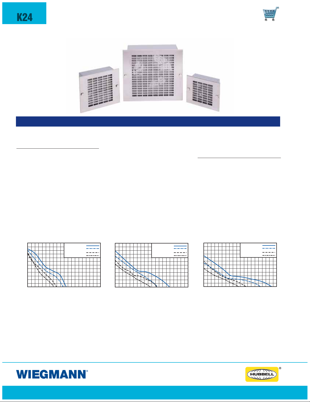
WPFB/WPFBE FILTERED BOX FANS & GRILLES
FEATURES-SPECIFICATIONS
Applications
Used for enclosure cooling in low static
pressure applications.
Features
• High airflow with low noise operation makes these versatile cooling
fans very popular in a wide range
of applications
• Reliable cooling is achieved particularly in areas with minimum space
requirements
• The cooling system incorporates the
filtered fan boxes as its air inlet, while
the exhaust grille is the air outlet
PERFORMANCE GRAPHS
WPFB100
.30
.15
STATIC PRESSURE
.03
10
50
AIRFLOW C.F.M.
KP40
60 Hz.
Fan:
50 Hz.
60 Hz.
Unit:
50 Hz.
100 15 00 200
• The washable aluminum filter grille
and air filter is easily accessible
and can be removed for cleaning
• Available in 115 VAC or 230 VAC
50/60 Hz versions
• Heavy gauge steel construction
• Attractive, ascetically appealing
grille design
• All models can pressurize or
exhaust
• Aluminum filter is coated with
adhesive baffle surfaces for dust
and dirt collection. Can be recoated
after cleaning for optimum performance
WPFB200
1. 0
.5
STATIC PRESSURE
.1
15
0 300
75
60
Fan:
Unit:
150 225
AIRFLOW C.F.M.
60 Hz.
50 Hz.
60 Hz.
50 Hz.
Note: One grille and filter are included with each fan package. Normally,
an additional exhaust grille and filter
required for each installation and
must be ordered separately.
Accessories
• Exhaust Grille and Filters
(see page L25)
• Filter Coat
WPFB500
.50
.25
STATIC PRESSURE
.05
30
150
AIRFLOW C.F.M.
KP100
60 Hz.
Fan:
50 Hz.
60 Hz.
Unit:
50 Hz.
300 4500 600
Static pressure is in inches of water.
www.hubbell-wiegmann.com
Data Subject To Change Without Notice
Page 25

ENVIRONMENTAL CONTROLS
WPFB/WPFBE SERIES FILTERED BOX FANS & GRILLES
K25
“WPFBE” Exhaust Grille with Filter Filter Coat“WPFB” Box Fan
FEATURES-SPECIFICATIONS
WPFB SERIES BOX FANS
CATALOG FREE-FLOW AIR RATED NOMINAL RUNNING
NUMBER DELIVERY (CFM) VOLTAGE (RPM) AMPS
WPFB100115 105 115 3000 0.18 15
WPFB100230 105 230 3000 0.18 15
WPFB200115 210 115 3300 0.29 33
WPFB200230 210 230 3300 0.29 33
WPFB500115 560 115 1600 0.87 60
WPFB500230 560 230 1600 0.87 60
WPFBE SERIES EXHAUST GRILLES WITH FILTERS
CATALOG NUMBER
WITH FILTER FILTER ONLY
WPFBE100 WPFBM100
WPFBE200 WPFBM200
WPFBE500 WPFBM500
ABDEFGW*
6.13 7.38 5.62 6.38 4.13 0.75 5.66
(156) (188) (143) (162) (105) (19) (144)
7.63 8.88 7.12 7.88 4.50 1.31 7.16
(194) (226) (181) (200) (114) (33) (182)
11.62 13.00 11.13 11.88 6.88 2.13 11.16
(295) (330) (283) (302) (175) (54) (283)
WATTS A B C D E F G H
Industry
Standards
UR, cUR, and CE recognized
6.13 7.38 2.38 5.62 6.38 4.13 0.75 7.00
(156) (188) (61) (143) (162) (105) (19) (178)
6.13 7.38 2.38 5.62 6.38 4.13 0.75 7.00
(156) (188) (61) (143) (162) (105) (19) (178)
7.63 8.88 3.00 7.12 7.88 4.50 1.31 8.50
(194) (226) (76) (181) (200) (114) (33) (216)
7.63 8.88 3.00 7.12 7.88 4.50 1.31 8.50
(194) (226) (76) (181) (200) (114) (33) (216)
11.62 13.00 4.56 11.13 11.88 6.88 2.13 12.50
(295) (330) (116) (283) (302) (175) (54) (318)
11.62 13.00 4.56 11.13 11.88 6.88 2.13 12.50
(295) (330) (116) (283) (302) (175) (54) (318)
FILTER COAT
CATALOG
NUMBER
WAX10 10 oz pump spray bottle
DESCRIPTION
C
D
H
E
0.19 DIA 4 PLACES
D
F
G
AIR
FLOW
B
A
0.36
D
E
F
D
G
www.hubbell-wiegmann.com
Data Subject To Change Without Notice
Page 26

K26
ENVIRONMENTAL CONTROLS
MUFFIN FANS & FINGER GUARDS
FEATURES-SPECIFICATIONS
WAGARD6WA4AXFN
MUFFIN FANS &
FINGER GUARDS
Applications
Designed for use in enclosures where
space is limited and reliable cooling
is required.
Features
• Fan furnished standard with 24"
lead wire. 90 degree plug attached
• Black color
• Impeller and frame are glass
reinforced thermoplastic, UL94-VO
• Die cast aluminum housing
WAXFN SERIES MUFFIN FANS & WAGARD SERIES FINGER GUARDS
CATALOG NUMBER
FAN
WA4AXFN WAGARD4 115 17/15 50/60 2500/3000 37 ± 2 2.5/3.1 88/110 5.8/7.0 4.71x4.71x1.50 (120x120x38)
WA4AXFN2 WAGARD4 230 17/15 50/60 3500/3000 37 ± 2 2.5/3.1 88/110 5.8/7.0 4.71x4.71x1.50 (120x120x38)
WA6AXFN WAGARD6 115 26/35 50/60 2800/3500 46 ± 2 5.4/6.6 190/235 5.4/6.6 6.77x6.77x2.01 (172x172x51)
WA6AXFN2 WAGARD6 230 26/35 50/60 2800/3500 46 ± 2 5.4/6.6 190/235 5.4/6.6 6.77x6.77x2.01 (172x172x51)
WA10AXFN WAGARD10 1 15 35 5 0/ 60 1650 5 5 547 10 10.00x10.00x3.50 (254x254x89)
WA10AXFN2 WAGARD10 230 33 50/60 1650 55 547 10 10.00x10.00x3.50 (254x254x89)
FAN
GUARD (WATTS) (RPM)
VOLTAGE
RATING
RATED
INPUT
FREQ
(Hz)
RATED
SPEED
MAXIMUM AIR FLOW
NOISE
LEVEL
(M3/MIN) CFM
• Finger guards are welded electroplated nickel chrome steel wire.
Guards withstand 200 lbs. separation
force to meet UL, CSA standards
• One finger guard and all mounting
hardware is provided. Additional
finger guards can be mounted on
either side for maximum safety
MAXIMUM
STATIC
PRESSURE/H20
DIMENSIONS
HXWXD
www.hubbell-wiegmann.com
Data Subject To Change Without Notice
Page 27

WAVK, WAVK-SS & WAFLT LOUVER PLATE KITS & FILTER KITS
WAVK0303SSA WAFLT33
FEATURES-SPECIFICATIONS
ENVIRONMENTAL CONTROLS
K27
LOUVER PLATE KITS
Description
Designed to provide ventilation or cooling in enclosures
where excessive moisture or excessive internal heat is
a problem. These kits are fabricated from 14 gauge steel
and include all hardware for mounting. Kits are easily field
installed by making a cutout of the proper size and attaching
the louver plate in place. Finish is ANSI 61 gray polyester
powder finish over phosphatized surfaces or 316 stainless
FILTER KITS FOR LOUVER PLATES KITS
Description
Designed for use with Louver Plate Kit. Mounting holes
on filter brackets align with mounting holes on louver kits.
Aluminum filters are good for stopping dust and dirt from
penetrating the enclosures. Filters are designed to mount
behind louver kits. Kit consists of aluminum filter, brackets
and all necessary hardware for installation. Louver kit must
be ordered separately.
steel. Filter kit must be ordered separately.
WAVK SERIES LOUVER PLATE KIT AND WAFLT SERIES FILTER KITS FOR LOUVER PLATES
LOUVER KIT LOUVER KIT
PAINTED 316 S.S.
WAVK0203 WAVK0203SSA —31
WAVK0303 WAVK0303SSA WAFLT33 31
WAVK0304 WAVK0304SSA WAFLT34 41
WAVK0404 WAVK0404SSA WAFLT44 41
WAVK0604 WAVK0604SSA WAFLT64 81
WAVK0606 WAVK0606SSA WAFLT66 12 1
WAVK0806 WAVK0806SSA WAFLT86 12 2
WAVK0808 WAVK0808SSA WAFLT88 16 2
WAVK0812 WAVK0812SSA WAFLT812 24 2
Note: Center holes (dimension “S”) are not needed on any filter kits. Only 6x6andlargerlouverkits require center holes.
CATALOG NUMBER
FILTER KIT
NUMBER NUMBER
OF OF LOUVER
LOUVERS ROWS
LOUVER
LENGTH
2.00 3.25 3.25 2.00 2.00 2.50 2.50 —
(51) (83) (83) (51) (51) (64) (64)
3.00 3.87 4.50 2.62 3.25 3.12 3.75 —
(76) (98) (114) (67) (83) (79) (95)
3.00 4.75 4.50 3.50 3.25 4.00 3.75 —
(76) (121) (114) (89) (83) (102) (95)
4.00 5.62 5.50 4.37 4.25 4.87 4.75 —
(102) (143) (140) (111) (108) (124) (121)
3.00 5.62 7.50 4.37 6.25 4.87 6.75 —
(76) (143) (191) (111) (159) (124) (171)
3.00 7.87 7.50 6.62 6.25 7.12 6.75 3.56
(76) (200) (191) (168) (159) (181) (171) (90)
4.00 8.18 9.50 6.93 8.25 7.43 8.75 3.71
(102) (208) (241) (176) (210) (189) (222) (94)
4.00 10.56 9.50 9.31 8.25 9.81 8.75 4.90
(102) (268) (241) (236) (210) (249) (222) (124)
4.00 15.31 9.50 14.06 8.25 14.56 8.75 7.28
(102) (389) (241) (357) (210) (370) (222) (185)
ABLMPR S
www.hubbell-wiegmann.com
Data Subject To Change Without Notice
Page 28

K28
ENVIRONMENTAL CONTROLS
WAVK, WAVK-SS & WAFLT LOUVER PLATE KITS & FILTER KITS
Notes:
Installation Instructions
1. M akesurethe proper louver kit and/or filter kit has been ordered.
2. Locate and mar kholes and cutout as showninfigure 1.
3. Drill holes using a 7/32"drill bit making sure there are no electrical
wires or internal components in the way.
4. Assemble louver kits and/or filter kits as showninfigure 2.
Note: After installation is complete, make sure louver andfilter kits
do not interfere with any internal or external equipment.
www.hubbell-wiegmann.com
Data Subject To Change Without Notice
Page 29

ENVIRONMENTAL CONTROLS
EHG SERIES ENCLOSURE RADIANT HEATERS
K29
EHG030
FEATURES-SPECIFICATIONS
Applications
Designed to provide enclosed electronic,
pneumatic, hydraulic, and mechanical
equipment with protection from low
temperatures, condensation, and
corrosion.
Features
• Positive Temperature Coefficient
heater unit maintains a stable temperature environment within enclo-
EHG SERIES ENCLOSURE RADIANT HEATERS
CATALOG
NUMBER VOLTAGE H X W X D
EHG015 15 110 - 250 50/60 2.60x2.80x2.00 (65x70x50)
EHG030 30 110 - 250 50/60 2.60x2.80x2.00 (65x70x50)
EHG045 45 110 - 250 50/60 2.60x2.80x2.00 (65x70x50)
EHG060 60 110 - 250 50/60 5.50x2.80x2.00 (140x70x50)
EHG075 75 110 - 250 50/60 5.50x2.80x2.00 (140x70x50)
EHG100 100 110 - 250 50/60 5.50x2.80x2.00 (140x70x50)
EHG150 150 110 - 250 50/60 8.70x2.80x2.00 (220x70x50)
*Due to the nature of PTC heaters, the actual power rating of the heater can be up to 10% lower,
or 5% higher than the nominal power rating at 68ºF (20ºC) ambient temperature.
WATTS*
RATED
sures, allowing critical components
to perform with consistent reliability
for longer periods
• Expanded voltage range of 110V
to 230V
• Heating body is extruded, black
anodized, aluminum
• Easily installed by clip mounting on
35mm DIN rails
• Connection: Push-type terminals
Hz
DIMENSIONS
Industry
Standards
UL Recognized Component
cUL Recognized Co m ponent
CE Recognized
• Max surface temperature of heater
is 194°F
• Protection Class: 1 (tested for
grounding at 1,600V)
• CAUTION— Do not mount on wooden structures. Avoid placement
near heat-sensitive components
Accessories
• Thermostats (see pages K33-K34)
www.hubbell-wiegmann.com
Data Subject To Change Without Notice
Page 30

K30
F
F
P
P
O
O
FEATURES-SPECIFICATIONS
ENVIRONMENTAL CONTROLS
WHVL SERIES ENCLOSURE F
F
WHVLO31100120
AN HEATERS
Industry Standards
UL Recognized Component
cUL Recognized Component
CE Recognized
Applications
Used when larger heating capacities
or internal forced air circulation is
required and space is limited.
Features
• Compact design to prevent
condensation or maintain minimum
temperature in enclosures
• Cartridge heater heating element
WHVL SERIES ENCLOSURE FAN HEATERS
CATALOG RATED
NUMBER VOLTAGE
WHVLO31100120 120 100 0.89 250ºF (120ºC) 1.85x3.15x4.41(47x80x112)
WHVLO31150120 120 150 1.30 320ºF (160ºC) 1.85x3.15x4.41(47x80X112)
WHVLO31200120 120 200 1.79 250ºF (120ºC) 1.85x4.68x5.94(47x119x151)
WHVLO31300120 120 300 2.62 320ºF (160ºC) 1.85x4.68x5.94(47x119x151)
WHVLO31400120 120 400 3.45 360ºF (180ºC) 1.85x4.68x5.94(47x119x151)
WATTS CURRENT TEMPERATURE
OPERATING MAXIMUM
(AMPS) WITH FAN
• 50,000 hour life expectancy at
77˚F ambient
• Connection: 5 pole terminal for
max. 14 AWG
• Easily installed by clip mounting
on 35mm DIN rails
• Protection class 1 (tested for
grounding at 1,500 V)
• Heater comes fully assembled
with fan
DIMENSIONS
H X W X D
• CAUTION— Do not mount on
wooden structures. Avoid placement
near heat-sensitive components.
Note that fan must be used in
conjunction with heating element
Accessories
• Thermostats (see pages K33-K34)
• Also available in 230 V
100 & 150W Heaters 200, 300 & 400W Heaters
www.hubbell-wiegmann.com
Data Subject To Change Without Notice
Page 31

ENVIRONMENTAL CONTROLS
WCR SERIES FAN HEATERS
K31
Industry
Standards
UL Recognized Co m p o n ent
cUL Recognized Component
WCR027350120
CE Recognized
FEATURES-SPECIFICATIONS
Applications
Designed to protect sensitive
mechanical, electrical, and electronic
equipment from the harmful effects
of condensation, corrosion, and low
temperatures. Thermostatically controlled
fan-driven heater units maintain a
stable temperature with enclosure so
critical components can perform more
reliably over a longer period of time.
WCR SERIES FAN HEATERS
CATALOG RATED MAX. AMPS THERMOSTAT AXIAL FAN TEMPERATURE DIMENSIONS
NUMBER VOLTAGE
WCR027350120 120 550 11A 32-140ºF (0-60ºC) 20 CFM Fahrenheit 6.50x3.94x5.00 (165x100x128)
WCR027350230 230 400 13A 32-140ºF (0-60ºC) 20 CFM Celsius 6.50x3.94x5.00 (165x100x128)
WCR027550120 120 650 14A 32-140ºF (0-60ºC) 26 CFM Fahrenheit 6.50x3.94x5.00 (165x100x128)
WCR027550230 230 550 15A 32-140ºF (0-60ºC) 26 CFM Celsius 6.50x3.94x5.00 (165x100x128)
WATTS
(INRUSH CURRENT) ADJUSTABLE FROM BALL BEARING SCALE H X W X D
Features
• Positive Temperature Coefficient (PTC)
semiconductor heating element, self
regulating and temperature limiting
• Adjustable thermostat
• LED lamp for optical indication of
function
• Durable, non-metallic plastic housing, UL94-VO
• Connection: 2 - pole terminal, max.
AWG 14
• Easily installed by clip-mounting on
35mm DIN rail
• CAUTION— Do not mount on
wooden structures. Avoid placement
near heat-sensitive components
For spacing, add 2" clearance for heat sensitive parts
www.hubbell-wiegmann.com
Data Subject To Change Without Notice
Page 32

K32
ENVIRONMENTAL CONTROLS
EGL SERIES F
AN HEATERS
FEATURES-SPECIFICATIONS
EGL250-120
Industry Standards
UL Recognized Component
cUL Re cognized Component
CE Recognized
VDE Approval
Applications
• Use when larger heating capacities
or internal forced air circulation
is required.
• Designed to prevent condensation
or maintain minimum temperature
in enclosures.
Features
• Heating element is micanite with
fail safe thermostat
• Silver, anodized aluminum extruded
body
• Ball bearing life expectancy is
50,000 hrs. at 77ºF (20ºC)
• Easily installed by clip mounting on
35mm DIN rails
• CAUTION— Do not mount on
wooden structures. Avoid placement
near heat-sensitive components
Accessories
• Thermostats (see pages K33-K34)
• Connection: 3 pole terminal for
AWG 16 max, with strain relief
EGL SERIES FAN HEATERS
CATALOG RATED STARTING SURFACE
NUMBER VOLTAGE
EGL250-120 120 250 2.2 167ºF Ball Bearing 32 CFM Free Blowing 7.20x3.15x3.94 (182x80x100)
EGL250 230 250 1.1 167ºF Ball Bearing 26 CFM Free Blowing 7.20x3.15x3.94 (182x80x100)
EGL400-120 120 400 3.5 167ºF Ball Bearing 32 CFM Free Blowing 8.70x3.15x3.94 (222x80x100)
EGL400 230 400 1.7 167ºF Ball Bearing 26 CFM Free Blowing 8.70x3.15x3.94 (222x80x100)
WATTS
AMPS TEMPERATURE POWER H X W X D
AXIAL FAN
CIRCULATION DIMENSIONS
For spacing, add 2" clearance for heat sensitive parts
www.hubbell-wiegmann.com
Data Subject To Change Without Notice
Page 33

ETR202 ETR202F ZR011
FEATURES-SPECIFICATIONS
ENVIRONMENTAL CONTROLS
& ZR SERIES THERMOSTATS
ETR
• Twothermostats in one unit
– one Normally Closed (NC)
and one Normally Open (NO)
– or two Normally Open (NO)
• Eachwithwideadjustable tem-
perature range
• Available with°For°C scale
• DIN rail mountable
Industry Standards
UL Recognized Component
cUL Recognized Component
CE Recognized
CSA Rated
K33
Applications
ETR202C and ETR202F
• Designed to provide air temperature
control and monitoring in switch
gear enclosures that are set up to
operate with heaters, fans, filter
ventilators, heat exchangers,
and/or signal transmitters.
• When the enclosure reaches the
pre-determined set point, temperature contacts in the thermostat are
activated and the fan or heater
automatically begins to operate.
• Thermostats prolong the life
expectancy of heaters and fans by
curtailing their operating hours and
also increase the working efficiency
of electrical components by exposing them to fewer contaminants from
the surrounding environment.
ZR011
• The ZR011 houses two separate
thermostats, allowing the independent
control of heating and cooling or
other equipment. Both thermostats
offer wide adjustment ranges and
are color coded for easy function
recognition.
• Switching capacity:
NC: 10A resistive/2A inductive
@250VAC
NO: 5A resistive/2A inductive
@250VACDC30W
Features
• Normally Closed Thermostat — For
the control of fan heaters and heaters
• Normally Open Thermostat — For the
control of cooling units, fans, filter
ventilators or switching, or signal
transmitters in the event of overheating
• Available in Fahrenheit or Celsius scale
• Thermostatic bi-metallic sensor element
• Housing made from gray flame
retardant UL94-VO plastic
• Connection: 2 pole terminal for max.
14 AWG
• Switching Difference (hysteresis):
12ºF (7ºC)
• Switching Capacity: 15 A (2) AC
120V, 10 A (2) AC 250V, 10A 12V
DC, 5A 24V DC
• Easily installed by clip mounting on
35mm or 38mm DIN rails
ETR & ZR SERIES THERMOSTATS
CATALOG TEMP. TEMP.
NUMBER SCALE RANGE TYPE HXWXD
ETR202F Fahrenheit 32-140ºF Normally Closed Heating 2.40x1.30x1.40 (60x33x35)
ETR202 Celsius 0-60ºC Normally Closed Heating 2.40x1.30x1.40 (60x33x35)
ETR201F Fahrenheit 32-140ºF Normally Open Cooling 2.40x1.30x1.40 (60x33x35)
ETR201 Celsius 0-60ºC Normally Open Cooling 2.40x1.30x1.40 (60x33x35)
ZR 011F Fahrenheit 32-140ºF
ZR 011C Celsius 0-60ºC
SWITCHING
Normally Closed/
Normally Open
Normally Closed/
Normally Open
FOR PRODUCT DIMENSIONS
Heating/Cooling 2.60x2.00x1.80 (67x50x46)
Heating/Cooling 2.60x2.00x1.80 (67x50x46)
www.hubbell-wiegmann.com
Data Subject To Change Without Notice
Page 34

K34
ENVIRONMENTAL CONTROLS
ETF SERIES THERMOSTATS
FEATURES-SPECIFICATIONS
ETF-3000
Industry Standards
UL Recognized Component
cUL Recognized Component
CE recogn ized
Applications
• Designed to provide both air temperature and humidity control as well
as monitoring in electrical and electronic enclosures.
• Highly effective in ATM’s, parking
control gates, ticket dispensers and
traffic control systems where equipment is exposed to wide range of
Features
• Independently senses the relative
humidity and temperature. Resistive
and inductive loads (heaters or
Filterfans
™
) can be switched
• 100,000 cycle life expectancy
• LED lamp for optical indication
of function
• Durable, non metallic plastic gray
housing, UL94-VO
• Easily installed by clip mounting
on 35mm DIN rail
• Switching capacity: 8A(4) AC 240V,
0.8A DC 48V, 8A DC 24V
outdoor elements.
ETF SERIES FAN HEATERS
CATALOG OPERATING TEMPERATURE
NUMBER VOLTAGE SCALE
ETF3000120F 120 Fahrenheit Approx. 3.6ºF (2ºK) Approx. 160 32-140ºF 50 to 90% 2.64x1.97x1.54 (67x50x39)
ETF3000 230 Celsius Approx. 3.6ºF (2ºK) Approx. 160 0-60ºC 50 to 90% 2.64x1.97x1.54 (67x50x39)
SWITCHING RESPONSE
DIFFERENCE TIME
(HYSTERESIS) (SECONDS)
TEMPERATURE RELATIVE DIMENSIONS
RANGE HUMIDITY RANGE H X W X D
www.hubbell-wiegmann.com
Data Subject To Change Without Notice
Page 35

STFX05
FEATURES-SPECIFICATIONS
ENVIRONMENTAL CONTROLS
STFX SERIES UNIVERSAL THERMOST
AT MOUNT
K35
Applications
Effective substitute for DIN rail or
“Unistrut”. Multipurpose mounting
devise which allow the mounting of
small DIN rail mountable appliances
reducing time and labor.
Features
• Provides direct snap-in mounting
for thermostats, time relays, small
heaters, terminals, and other
appliances with DIN rail mounting
or by the use of screw holes
• Manufactured from black UL94-VO
polyamide material
• Included self adhesive bears
continuous loads of 1.1 lbs.
(after 24 hours)
• Holes for screw mounting are
provided for heavy applications
STFX SERIES UNIVERSAL THERMOSTAT MOUNT
CATALOG HOLDING PACKAGE TEMP. RANGE OF DIMENSIONS
NUMBER CAPACITY QUANTITY* MOUNTING MATERIAL H X W X D
STFX05 1.1 lbs. (500g) after 5
.44 lbs. (200g) initially
24 hour curing period
*Sold in package quantity only
-22-131ºF 1.50x1.70x.55
(-30-55ºC) (38x43x14)
www.hubbell-wiegmann.com
Data Subject To Change Without Notice
Page 36

K36
ENVIRONMENTAL CONTROLS
WAFMP SERIES FAN MOUNTING PLATE
FEATURES-SPECIFICATIONS
WAFMP4
Fan Mounting Plate
Description
Designed to mount a fan and louver
kit together. This fan mounting plate
kit consists of a fan mounting plate,
filter and all necessary hardware for
installation. When ordering a fan
mounting plate, you will need to
order a fan, louver kit and a fan
guard. Fans, louver kits and fan
guards must be ordered separately.
Note: Fan guard, fan
and louver plate are
not included in kit.
Order separately.
WAFMP SERIES FAN MOUNTING PLATE
CATALOG NUMBER
FAN, FILTER & LOUVER
MOUNTING PLATE KIT PAINTED** GUARD ***
WAFMP4 WA4AXFN WAVK0606 WAGARD4
WAFMP4 WA4AXFN2 WAVK0606 WAGARD4
WAFMP6 WA6AXFN WAVK0806 WAGARD6
WAFMP6 WA6AXFN2 WAVK0806 WAGARD6
WAFMP10 WA10AXFN WAVK0812 WAGARD10
WAFMP10 WA10AXFN2 WAVK0812 WAGARD10
*See page K26 for information on fans.
**See page K27 for information on louver kits.
***See page K26 for information on guards.
FAN*
LOUVER KIT FAN
Notes:
Installation Instructions:
1. Make sure that the proper kits have been ordered.
2. Locate and mark holes and cutout per louver kit
instructions on page K27-K28.
3. Assemble kits as shown in figure 1.
4. After installation is complete, make sure that no
e interferes with any internal or external
hardwar
equipment.
www.hubbell-wiegmann.com
Data Subject To Change Without Notice
Page 37

1800 SERIES - FILTER FANS/EXHAUST FILTER & MATS
SERIES 1803
FEATURES-SPECIFICATIONS
ENVIRONMENTAL CONTROLS
SERIES 1800, 1801, 1802
K37
Industry standards
IP54
IP55 (with fine filter mat)
UR Recognized component
Application
• The latest passive technology for
fan cooling and pressurizing of
industrial enclosures
• Filtered passive ventilation can be
provided by an exhaust filter for
either convection cooling or in
combination with a fan in forced
air cooling
Features
• All four models are available in 120
and 230 volt with an expected service life of 50,000 hours
• Self-adhesive seal on mounting
frame prevents dust and water from
entering the enclosure
• The functional design of the intake
exhaust fan hoods minimize direct
infiltration of falling water
• By simply turning the axial fan, the
direction of the airflow can be
changed by 180 degrees
• Air Channeling makes the filter fan
particularly quiet in operation
• Plastic self-extinguishing UL94-V0
and temperature resistant –31˚F to
158˚F
• Durable, reusable medium filter mat
included
• RAL7035 Light Gray Finish
• Ball Bearing Axial Fan with plastic
impeller UL94V-01. 2 lead wires
4" long (pressure clamps inclusive)
Time-Saving Assembly and Maintenance
Time-Saving Steps
1800 Series Fans can be easily connected and installed from the outside
of the cabinet.
1. Remove protective film from the
sealing strips provided on the
mounting frame
2. Insert mounting frame into enclosure cutout.
3. Terminate the axial fan with push
type connectors and slide the unit
into the mounting frame.
4. Insert the Filter Mat and snap on
the protective Hood.
www.hubbell-wiegmann.com
Data Subject To Change Without Notice
Page 38

K38
ENVIRONMENTAL CONTROLS
1800 SERIES - FILTER FANS/EXHAUST FILTER & MATS
3.4"
2.3"
5.1"
1.4"
5.1"
1.6"
6.2"
2.0"
8.2"
11.2" (284mm)
2.6"
(68mm)
1.8"
(45mm)
3.8"
5.3"
4.9"
6.7"
6.9"
8.9"
9.8" (250mm)
1800 SERIES FILTER FAN
Catalog No. (for 120V 60Hz) W01800120-4 W01801120-5 W01802120-7 W01803120-10
Catalog No. (for 230V 50Hz) W01800230-4 W01801230-5 W01802230-7 W01803230-10
Filter mat: Medium grade 350 g/m , filtering degree 83%, Particle < 10 μm, G4(EN779)
Air volume
free blowing: 12 cfm (21 m
with exhaust filter: 9 cfm (16 m
3
/h) 35 cfm (55 m3/h) 60 cfm (102 m3/h) 176 cfm (300 m3/h)
3
/h) 24 cfm (42 m3/h) 40 cfm (68 m3/h) 135 cfm (230 m3/h)
Current consumption 120V 160 mA 180 mA 180 mA 400 mA
230V 80 mA 100 mA 100 mA 700 mA
Power consumption 120V 13W 15W 15W 60W
230V 13W 15W 15W 60W
Average noise level at 3 ft
DIN EN ISO 9614-2 31 dB (A) 40 dB (A) 39 dB (A) 53 dB (A)
Mounting depth 1.8" (45 mm) 2.3" (58 mm) 3.4" (86 mm) 2.6" (65 mm)
Enclosure cut-out 3.8" x 3.8" (97 x 97mm +0.4) 4.9" x 4.9" (125 x 125mm +0.4) 6.9" x 6.9" (176 x 176mm +0.4) 9.84" x 9.84" (250 x 250mm)
Weight 1.2 lbs (0.54 kg) 2.2 lbs (1.0 kg) 4.2 lbs (1.9 kg) 7.7 lbs (3.5 kg)
120V / 60Hz models have increased air volume performance of approx. 15%
1800 SERIES EXHAUST GRILLE & FILTER
Catalog No. W11800F-4 W11801F-5 W11802F-7 W11803F-10
Filter mat: Medium grade 350 g/m
2
, filtering degree 94%, Particle Ø to 10 μm, G4 (DIN 24185)
Mounting depth 0.6" (16 mm) 0.6" (16 mm) 0.6" (16 mm) 9" (22 mm)
Enclosure cut-out 3.8" x 3.8" (97 x 97mm +0.4) 4.9" x 4.9" (125 x 125mm +0.4) 6.9" x 6.9" (176 x 176mm +0.4) 9.8" x 9.8" (250 x 250mm +.4)
Weight 0.6 lbs (0.27 kg) 0.8 lbs (0.38 kg) 1.3 lbs (0.60 kg) 2.1 lbs (95 kg)
REPLACEMENT FILTER MATS*
Medium filter (G4) MM08600-4 MM08601-5 MM08602-7 MM08608-10
Fine filter (F5) FM08603-4 FM08604-5 FM08605-7 FM08609-10
*Box of (3)
MOUNTING FRAME HOLE CENTERS FOR ATTACHING WITH SCREWS - HOLE Ø 1/8” (3MM)
X = 4.3" (109 mm) X = 5.4" (137 mm) X = 7.4" (188 mm) X = 10.4" (264 mm)
Y
X
www.hubbell-wiegmann.com
Data Subject To Change Without Notice
Page 39

WPF10-115BK
FEATURES-SPECIFICATIONS
ENVIRONMENTAL CONTROLS
WPF SERIES FILTERFANS™
Industry Standards
UR, cUR, and CE recognized
IP43
(IP54 with optional WPFG Series gasket)
K39
Applications
•
Most innovative technology for fan
cooling and pressurizing of industrial enclosures
• Provides a high quality, economical
method of cooling enclosures
• Filtered passive ventilation can be
provided by an exhaust filter for
either convection cooling or in
combination with a fan in forced
air cooling
• Slim line design allows grille to
protrude from enclosure surface
less than one quarter inch
• Maintains aesthetics of enclosure
Features
• All models are 115V with an expected
service life of 30,000 hours
• High performance fan motors and
finger guards
• Polycarbonate fire retardant plastic
grilles, UL94-VO
• Durable, reusable filter mat included
• Grilles are available in black or beige
• Patented “Click and Fit” system
allows for rapid filter fan and exhaust
filter installation without screws; this
time saving feature will cut installation time by up to 30 minutes from
traditional box fan packages
-0/+1 mm
WPF10 WPF20
-0/+1 mm
• Cutout template provided with
every unit
• Fan or exhaust filter simply snaps
into cutout opening
• Connector type: WPF10 Series 2,
12" wires. WPF20 – WPF60 Series
terminal strip
Accessories
• Exhaust Filters
• Gaskets (WPFG Series) recommended
if installing on enclosure with
textured finish (only WPF10)
• Replacement Filters
-0/+1 mm
WPF25
WPF30
-0/+1 mm
WPF50
WPF60
www.hubbell-wiegmann.com
Data Subject To Change Without Notice
Page 40
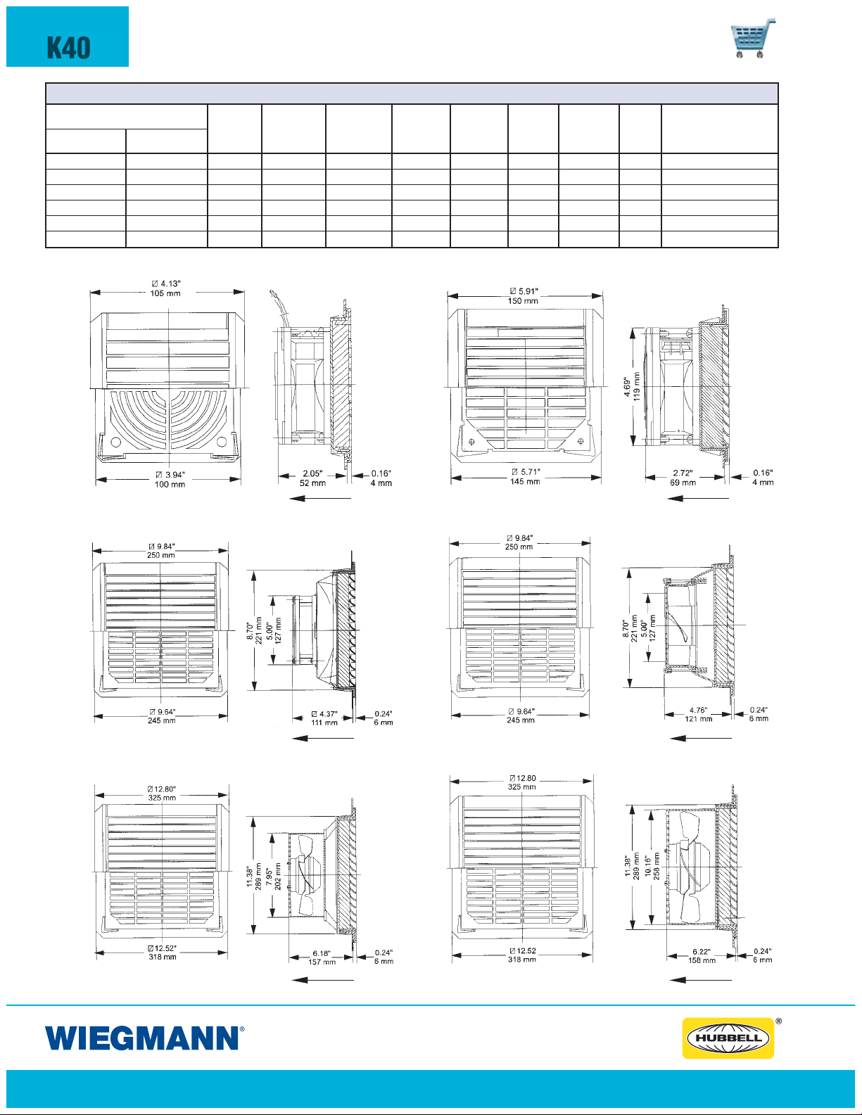
K40
ENVIRONMENTAL CONTROLS
WPF SERIES FILTERFANS™
WPF SERIES FILTERFANS™
CATALOG NUMBER
BLACK GRILLE BEIGE GRILLE
WPF10-115BK WPF10-115 115V 16.22 10.12 29.00 140/14 150.00 67% 39 3.62x 3.62 (92x92)
WPF20-115BK WPF20-115 115V 37.95 28.41 69.00 122/14 350.00 83% 49 4.92x 4.92 (125x125)
WPF25-115BK WPF25-115 115V 88.67 62.29 57.00 122/14 350.00 83% 55 8.78x 8.78 (223x223)
WPF30-115BK WPF30-115 115V 168.59 142.14 89.00 122/14 350.00 83% 55 8.78x 8.78 (223x223)
WPF50-115BK WPF50-115 115V 312.11 236.90 205.00 122/14 350.00 83% 69 11.46x11.46 (291x291)
WPF60-115BK WPF60-115 115V 423.09 304.64 225.00 122/14 350.00 83% 71 11.46x11.46 (291x291)
*Add 15% for operation @ 60Hz
RATED AIR DELIVERY STATIC TEMP.
VOLTAGE DELIVERY W/EXHAUST PRESSURE DEGREE F
FREE FLOW AIR MAX. AMBIENT
(CFM)* (CFM) (PA) MAX/MIN
FILTER SOUND
DENSITY
(G/M2)
FILTERING
LEVEL
LEVEL
(DB)
REQUIRED CUT OUT
DIMENSION
WPF10
WPF25
Air Flow Air Flow
Air Flow Air Flow
WPF20
WPF30
WPF50 WPF60
Air Flow Air Flow
www.hubbell-wiegmann.com
Data Subject To Change Without Notice
Page 41

WPFA10BK WPFA10
FEATURES-SPECIFICATIONS
ENVIRONMENTAL CONTROLS
WPFA SERIES EXHAUST GRILLE WITH FILTER
Industry Standards
IP43
(IP54 with optional WPFG Series gasket)
K41
Applications
• Polycarbonate fire retardant plastic
grilles, UL94-VO
• Durable, reusable filter mat included
• Grilles are available in black or beige
Accessories
• Gaskets (WPFG series) recommended if installing on enclosure
with textured finish
WPFA 10 WPFA 20
EXHAUST GRILLE WITH FILTER
CATALOG NUMBER
BLACK GRILLE
WPFA10BK WPFA10 150 67% 3.60x3.60/92x92
WPFA20BK WPFA20 350 83% 4.90x4.90/125x125
WPFA25/30BK WPFA25/30 350 83% 8.80x8.80/223x223
WPFA50/60BK WPFA50/60 350 83% 11.50x11.50/291x291
BEIGE GRILLE
FILTER FILTERING REQUIRED CUT OUT
DENSITY (G/M2) LEVEL DIMENSIONS
WPFA 25/30 WPFA 50/60
www.hubbell-wiegmann.com
Data Subject To Change Without Notice
Page 42

K42
ENVIRONMENTAL CONTROLS
FILTERFAN™ REPLACEMENT ACCESSORIES
WPFG25/30
FEATURES-SPECIFICATIONS
GASKETS FOR FILTERFANS
Applications
• Packaged individually
• Provides added sealing protection
• Recommended when fans or
exhaust grilles are installed on
enclosures with textured finishes
• Changes Filer Fan rating from IP43
to IP 54 when installed
AC & FILTERFAN
™
REPLACEMENT FILTER MATS
Applications
Replacement filter mat for WPF-115
Series Filterfans and WPFA Series
Exhaust Grilles.
Features
• Packaged in quantities of 5
• Made of synthetic fibers
• Re-usable up to 20 times
• 100% resistant to humidity
WPG1BKWPFM20 WPG25/30BE
™
WPFG SERIES GASKET FOR FILTERFANS™
GASKET USE WITH FILTER FAN NO. USE WITH EXHAUST GRILL NO.
WPFG10
WPFG20
WPFG25/30
WPFG50/60
AC & FILTERFAN™ REPLACEMENT FILTER MATS
FILTER USE WITH USE WITH MASS FILTER
CATALOG FILTER FAN EXHAUST FILTER DENSITY H W
NUMBER OR A/C SERIES GRILLE LEVEL % (G/M2)
WPFM10 WPF10-115 WPFA10 67 150 3.40 (85) 3.40 (85)
WPFM20 WPF20-115 WPFA20 83 350 4.50 (115) 4.50 (115)
WPFM25/30
WPFM50/60
WPFM25/30AC WDTS1200-6000 — 83 150 8.30 (210) 8.3 (210)
WPFM50/60AC WDTS8000-12000 — 83 150 11.00 (280) 11.00 (280)
WPFMDTTAC WDTT3500-4500 — 83 150 11.81 (300) 11.81 (300)
WPF25-115
WPF30-115
WPF50-115
WPF60-115
CATALOG NUMBER
WPF10-115BK WPFA10BK
WPF10-115 WPFA10
WPF20-115BK WPFA20BK
WPF20-115 WPFA20
WPF25-115BK WPFA25BK
WPF30-115BK WPFA30BK
WPF25-115 WPFA25
WPF30-115 WPFA30
WPF50-115BK WPFA50BK
WPF60-115BK WPFA60BK
WPF50-115 WPFA50
WPF60-115 WPFA60
WPFA30 83 350 8.30 (210) 8.30 (210)
WPFA50 83 350 11.00 (280) 11.00 (280)
FILTERFAN
™
REPLACEMENT GRILLES
Features
• Packaged individually
• Grille only replacement for filter fans
• Available in black or beige
FILTERFAN™ REPLACEMENT GRILLES
CATALOG NUMBER
BLACK BEIGE USE WITH GRILLE GRILLE FOR EXHAUST FOR EXHAUST
GRILLE GRILLE A/C UNIT GRILLE FOR FILTER FOR FILTER GRILLE GRILLE
WPG1BK WPG1BE — WPF10-115BK WP F10-115 WPFA10BK WPFA10
WPG2BK WPG2BE — WPF20-115BK WP F20-115 WPFA20BK WPFA20
WPG3BK WPG3BE WDTS1200-6000
WPG5BK WPG5BE WDTS6000-12000
BLACK BEIGE BLACK GRILLE BEIGE GRILLE
FAN FAN W/FILTER W/FILTER
WPF25-115BK WPF25-115 WPFFA25BK WPFA25
WPF30-115BK WP F30-115 WPFA30BK WPFA30
WPF50-115BK WPF50-115 WPFA50BK WPFA50
WPF60-115BK WPF60-115 WPFA60BK WPFA60
www.hubbell-wiegmann.com
Data Subject To Change Without Notice
Page 43

NOTES
www.hubbell-wiegmann.com
Data Subject To Change Without Notice
Page 44

NOTES
www.hubbell-wiegmann.com
Data Subject To Change Without Notice
 Loading...