

Page 1
Section F Index
F1
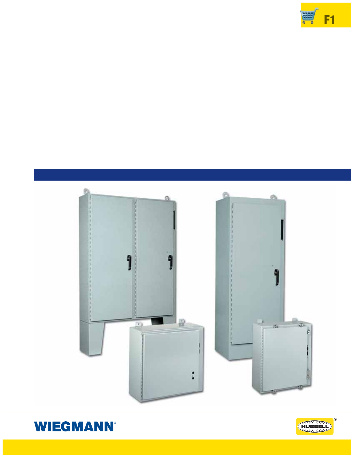
SDN12 Series
NEMA 12 Flanged Single Door
Disconnects ..........................................F3
N412CD, N412CDSS, N412CDSSA Series
ULTIMATE Flanged Single Door
Disconnects ..........................................F6
N412CSTD, N412CSSSTD Series
ULTIMATE Slope-Top Flanged
Single Door Disconnects .........................F8
SN4 Series
NEMA 4 Flanged Single Door
Disconnects ........................................F10
DISCONNECTS
SSN4X Series
NEMA 4 Flanged Single Door
Disconnects ........................................F12
ABN12 Series (1494F & 1494D)
NEMA 12 Flanged Single Door
Disconnects ........................................F23
WAX-U & WACPX-U Series
NEMA 12 Floor-Mount Disconnects ......F28
WAX-MU Series (1, 2, 3, 4, 5 Door)
NEMA 12 Heavy Duty Freestanding
Disconnects ..........................................F34
WMOD Series
NEMA 12 Modular Freestanding
Disconnects ........................................F40
WAX-SSN4, WACPX-SSN4 Series
NEMA 4X Floor Mount Disconnects .......F45
WAX-MSSN4 Series
NEMA 4X Freestanding Single & Double
Door Disconnects .................................F47
NEMA 12 Adapter Plates ....................F61
www.hubbell-wiegmann.com
Data Subject To Change Without Notice
Page 2
F2
ABN12 (V, U, C), & SDN12, SDN12PL, N412CD, N412CSTD, SN4, SSN4X SERIES
ENCLOSURES NEMA 12 FLANGED WALL MOUNT DISCONNECTS
• General Electric Type STDA flange handles and variable-
depth operating mechanisms for disconnect switches and
circuit breakers. Also SPECTRAFLEX
™
cable operators for
circuit breakers
• Siemens ITE Max-Flex
™
flange-mount variable-depth oper-
ating handles for circuit breakers.
• Schneider Square D
®
Class 9422 disconnect switches with
flange-mount variable-depth operating mechanisms or cable
mechanisms and Class 9422 flange-mount variable-depth
operating mechanism or cable mechanisms for circuit breakers.
These enclosures will not accept Schneider Square D
®
Class 9422 bracket-mounted disconnect devices, Class
9422TGI, or TG2 devices
“WM” PREFERRED CUTOUT
FEATURES-SPECIFICATIONS
Applications
These
General purpose disconnect enclosures accept major
brand disconnect switches and circuit breakers, available
with or without Wiegman-supplied defeater door handle and
handle hardware (door handle supplied on SDN12PL,
N412CD and N412CSTD models only).
Enclosures having the “WM” preferred cutout are sized for
use with up to 200A disconnect switches and up to 400A
circuit breakers unless otherwise specified. The “WM” preferred cutout accepts the smaller operating handle whose
mounting hole centers are 4.677 in. apart. “WM” preferred
cutouts are standard in mild steel wall-mount enclosures,
modular enclosures and some select large mild steel enclosures. They are also present on all standard stainless steel
offerings. Mild steel operator adapter plates with brand specific “WM” preferred cutouts are available for enclosures
with a rectangular universal cutout.
“WM” preferred cutouts are designed to house the following:
Allen-Bradley
• 1494V disconnect switches with flange-mount variable
depth operating mechanisms and 1494V flange-mounted
variable depth operating mechanisms for circuit breakers
• 140U flexible cable operating mechanisms and 140U
molded case circuit breakers
• 1494C cable-operated disconnect switches with flange-
mount handles
• 194RC cable-operated flange-mount handles for use with the
NFPA 79 compliant 194R IEC rotary disconnect switches
Allen-Bradley 1494V-R1, -R2 and -W2 operating handles and
Allen-Bradley 1494F disconnect devices or 1494D circuit
breaker operators will NOT fit these enclosures.
See Pages F20-F23 for ABN12 149F & 1494D models
• ABB Controls flange-mount variable-depth operating
mechanism for disconnect switches and circuit breakers.
Also the cable version for circuit breakers.
• Eaton Cutler-Hammer Type C361 flange-mount variable-
depth operating mechanisms with disconnect switches
and Type C371 flange-mount variable-depth operating
mechanisms for circuit breakers.
Important Ordering Information
Depending on model, order as follows:
On SDN12PL, N412 CD and N412CSTD Models
• Customer must order operating mechanism, operating
handle, and disconnect switch or circuit breakers from the
disconnect manufacturers (door handle and latching hardware included). See page F14 for ordering information.
On SDN12 and ABN12 V, U, C Models
• Customer must order operating mechanism and disconnect switch or circuit breakers, operating handle, and
door hardware from the disconnect manufacturers (see
page F14 for ordering information).
On SN4 and SSN4X Models
• Customer must order operating mechanism, operating
handle and disconnect switch or circuit breakers, from the
disconnect manufacturers (these models do NOT get
door hardware). See page F15 for ordering information.
Wire Bend Space
• See pages F16-F22 for wire bend space available when
various manufactures’ disconnect switches are installed.
Check the enclosure dimension drawings to verify the
chosen disconnect switch will fit in the enclosure.
Note:
E = 4.75 when Depth = 8.00
E = 7.09 when Depth = 10.00
E = 11.62 when Depth = 12.00 or 16.00
E = 18.38 for SDN 12603812A
WB = Wiring Space
See Pages F11-F19 for
various brands of disconnects for “F”, “G” & “WB”
dimensions.
Disconnects will occupy
space on panel shown by
dimensions “E”, “F” & “G”.
Wiring space “WB” is
available when disconnect
is installed in the enclosure.
Refer to National Electrical
Code article 430-10(b) for
wiring space required for
line side conductors to be
connected to disconnect.
Verify your application to
determine if wiring space
is adequate.
1.50
THIS SPACE IS
OCCUPIED BY
DISCONNECT
SWITCH AND
FUSE CLIP
(IF USED) OR
CIRCUIT
BREAKER
WB
G
TOP HOLE IN
R.H. FLANGE
E
FF
1.59
2.63
*Operator adapter plates are not required with these enclosures
www.hubbell-wiegmann.com
Data Subject To Change Without Notice
Page 3
FEATURES-SPECIFICATIONS
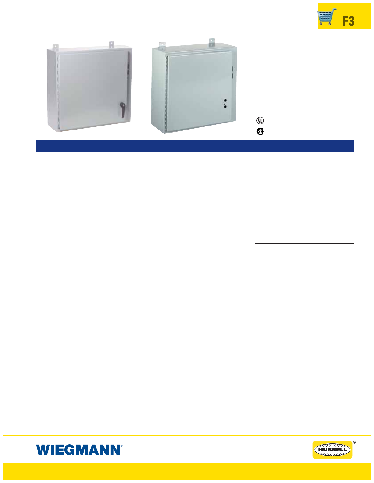
SDN12 & SDN12PL SERIES ENCLOSURES
NEMA 12 FLANGED SINGLE DOOR DISCONNECT
Industry Standards
UL 508
CSA Certified, Type 12
NEMA/EEMAC Types 12 & 13
,Types12&13
UL Files E64791
CSA File LL66078
F3
Construction
• Bodies and doors fabricated from
14 gauge steel
• Plasma welded seams
• Rolled lip around all sides of
enclosure opening excludes liquids
and contaminants
• Doors easily removed by pulling
continuous hinge pin
• Polyurethane poured-in-place gasket
• External mounting feet
• Collar studs for mounting optional
back panel
• Grounding provisions provided
• Holes are provided in body and
door for mounting operating handle,
operating mechanism, and door
closing mechanism
• Guide brackets and interlock door
catch are welded to the inside of
door
• A cover latch bar is also included
for door hardware
• Print pocket is provided
• Enclosures under 40" high require
2-point door hardware
• Enclosures 40" high and larger
require 3-point door hardware
• Instructions to locate and install
disconnect switches, circuit breakers, and operating mechanisms are
provided
• Enclosures available with or without
padlocking, defeater handle and
latching system
Fini sh
• ANSI 61 gray polyester powder
inside and out over phosphatized
surfaces
• Optional back panels are white
polyester powder over phosphatized surfaces
• Optional “G” panels have a con-
ductive finish
Acces sories
• Back panels (reference tables)
• Blank Adapter Plates on page F61
IMPORTANT Ordering Information
• See F2 for disconnect switch, circuit
breakers, operating handle and operating mechanism.
www.hubbell-wiegmann.com
Data Subject To Change Without Notice
Page 4
F4
SDN12 & SDN12PL SERIES ENCLOSURES
NEMA 12 FLANGED SINGLE DOOR DISCONNECT
SDN12 & SDN12PL SERIES WALL-MOUNT DISCONNECTS
CATALOG NUMBER BODY/DOOR ENCLOSURE SIZE BACK PANEL CATALOG NUMBER* BACK PANEL
WITH HANDLE WITHOUT HANDLE
STEEL GAUGE
H X W X D WHITE “G” SIZE A X B
SDN12202108PL SDN12202108 14/14 20.00x21.38x8.13 (508x543x206) NP2020 NP2020G 17.00x17.00 (432x432)
SDN12242108PL SDN12242108 14/14 24.00x21.38x8.13 (610x543x206) NP2420 NP2420G 21.00x17.00 (533x432)
SDN12242508PL SDN12242508 14/14 24.00x25.38x8.13 (610x645x206) NP2424 NP2424G 21.00x21.00 (533x533)
SDN12302108PL SDN12302108 14/14 30.00x21.38x8.13 (762x543x206) NP3020 NP3020G 27.00x17.00 (686x432)
SDN12302508PL SDN12302508 14/14 30.00x25.38x8.13 (762x645x206) NP3024 NP3024G 27.00x21.00 (686x533)
SDN12362508PL SDN12362508 14/14 36.00x25.38x8.13 (914x645x206) NP3624 NP3624G 33.00x21.00 (838x533)
SDN12363108PL SDN12363108 14/14 36.00x31.38x8.13 (914x797x206) NP3630 NP3630G 33.00x27.00 (838x686)
SDN12423208PL SDN12423208 14/14 42.00x31.38x8.13 (1067x797x206) NP4230 NP4230G 39.00x27.00 (991x686)
SDN12423708PL SDN12423708 14/14 42.00x37.38x8.13 (1067x949x206) NP4236 NP4236G 39.00x33.00 (991x838)
SDN12483708PL SDN12483708 14/14 48.00x37.38x8.13 (1219x949x206) NP4836 NP4836G 45.00x33.00 (1143x838)
SDN12603808PL SDN12603808 14/14 60.00x37.38x8.13 (1524x949x207) NP6036 NP6036G 57.00x33.00 (1448x838)
SDN12202110PL SDN12202110 14/14 20.00x21.38x10.25 (508x543x257) NP2020 NP2020G 17.00x17.00 (432x432)
SDN12242110PL SDN12242110 14/14 24.00x21.38x10.25 (610x543x257) NP2420 NP2420G 21.00x17.00 (533x432)
SDN12242510PL SDN12242510 14/14 24.00x25.38x10.25 (610x645x257) NP2424 NP2424G 21.00x21.00 (533x533)
SDN12302110PL SDN12302110 14/14 30.00x21.38x10.25 (762x543x257) NP3020 NP3020G 27.00x17.00 (686x432)
SDN12302510PL SDN12302510 14/14 30.00x25.38x10.25 (762x645x257) NP3024 NP3024G 27.00x21.00 (686x533)
SDN12362510PL SDN12362510 14/14 36.00x25.38x10.25 (914x645x257) NP3624 NP3624G 33.00x21.00 (838x533)
SDN12363110PL SDN12363110 14/14 36.00x31.38x10.25 (914x797x257) NP3630 NP3630G 33.00x27.00 (838x686)
SDN12423110PL SDN12423110 14/14 42.00x31.38x10.25 (1067x797x257) NP4230 NP4230G 39.00x27.00 (991x686)
SDN12423710PL SDN12423710 14/14 42.00x37.38x10.25 (1067x949x257) NP4236 NP4236G 39.00x33.00 (991x838)
SDN12483710PL SDN12483710 14/14 48.00x37.38x10.25 (1219x949x257) NP4836 NP4836G 45.00x33.00 (1143x838)
SDN12603710PL SDN12603710 14/14 60.00x37.38x10.25 (1524x949x257) NP6036 NP6036G 57.00x33.00 (1448x838)
SDN12302612PL SDN12302612 14/14 30.00x25.38x12.13 (762x645x308) NP3024 NP3024G 27.00x21.00 (686x533)
SDN12363212PL SDN12363212 14/14 36.00x31.38x12.13 (914x797x308) NP3630 NP3630G 33.00x27.00 (838x686)
SDN12423212PL SDN12423212 14/14 42.00x31.38x12.13 (1067x797x308) NP4230 NP4230G 39.00x27.00 (991x686)
SDN12423812PL SDN12423812 14/14 42.00x37.38x12.13 (1067x949x308) NP4236 NP4236G 39.00x33.00 (991x838)
SDN12483812PL SDN12483812 14/14 48.00x37.38x12.13 (1219x949x308) NP4836 NP4836G 45.00x33.00 (1143x838)
SDN12603812PL — 14/14 60.00x37.38x12.13 (1524x949x308) NP6036 NP6036G 57.00x33.00 (1448x838)
SDN12603812APL SDN12603812A** 14/14 60.00x37.38x12.13 (1524x949x308) NP6036 NP6036G 57.00x33.00 (1448x838)
SDN12363116PL SDN12363116 14/14 36.00x31.38x16.13 (914x797x410) NP3630 NP3630G 33.00x27.00 (838x686)
SDN12483816PL SDN12483816 14/14 48.00x37.38x16.13 (1219x949x410) NP4836 NP4836G 45.00x33.00 (1143x838)
SDN12603816PL SDN12603816 14/14 60.00x37.38x16.13 (1524x949x410) NP6036 NP6036G 57.00x33.00 (1448x838)
* Back panels must be ordered separately.
** Enclosure catalog number SDN12603812A will receive only 400 amp and 600 amp Allen-Bradley 1494V disconnect switches and Siemens ITE Max-Flex
800 amp and 1200 amp circuit breakers. The 400 amp and 600 amp Allen-Bradley disconnect switch will not fit any other size enclosure from the SDN12
family. Blank Adapter plates will not fit catalog number SDN12603812A. Enclosures 12" and 16" deep can be modified to accept Siemens ITE Max-Flex
800 amp and 1200 amp circuit breakers. (When using an Siemens ITE Max-Flex™circuit breaker and an enclosure with an “H” dimension of 30", 36" or 42",
™
verify the amount of wire bend space required for both the line and load sides.) Consult factory for details.
™
PL Version
www.hubbell-wiegmann.com
Data Subject To Change Without Notice
Notes:
1. Large print pocket (8"x10") is provided in each
enclosure
2. Panels are made from 12 Ga. steel
3. Panels have flanges along all sides when either
dimension exceeds 17"
4. Catalog number SDN12603812A has a larger
cutout in the enclosure flange to accommodate
the Allen-Bradley 1494V-H2 and I-T-E FHOHN
operating handles.
5. Enclosures under 40" high have 2-point door
hardware and enclosures 40"highandlarger
have 3-point door hardware.
6. The handle includes a zinc diecast padlocking
defeater handle and all latching hardware is
installed on disconnect enclosures ending in PL.
Order separately for other disconnect enclosures.
7.
See Page F27 for Stiffener Location.
Page 5
SDN12 & SDN12PL SERIES ENCLOSURES
NEMA 12 FLANGED SINGLE DOOR DISCONNECT
F5
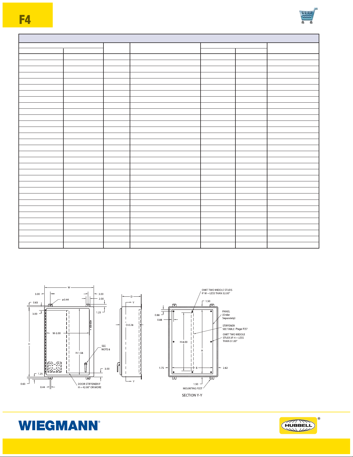
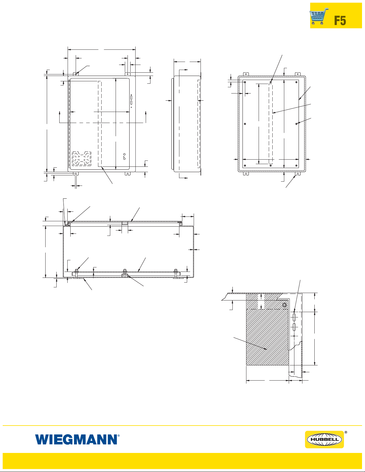
0.63
W
3.00
W-3.00
Ø0.44
GASKET
H-1.56
DOOR STIFFENER IF
H = 42.00"OR MORE
0.63
3.00
X
H
1.25
0.44
CONTINUOUS
HINGE
0.63
0.88
3.00
2.00
1.25
X
3.00
DOOR
STIFFENER
2.38
D
Y
0.88
0.88
D-0.28
H-6.00
Y
MOUNTING FEET
SECTION Y-Y
Notes:
1. Large print pocket (8"x10") is provided in each enclosure.
OMIT TWO MIDDLE STUDS
IF W = LESS THAN 32.00"
1.50
A
B1.75 2.62
1.50
PANEL
(Order
Separately)
STIFFENER
SEEPageF27
OMIT TWO MIDDLE
STUDSIFH= LESS
THAN 31.00"
2. Panels are made from 12 Ga. steel.
1.31
D
1.09
0.69
TYP
3/8 - 16 COLLAR
STUD
12 GA.
1.25 TYP
PA NE L
(ORDER SEPARATELY)
2.75
14 GA.
3. Panels have flanges along all sides when either dimension
exceeds 17".
4. Catalog number SDN12603812A has a larger cutout in the
enclosure flange to accommodate the Allen-Bradley
1494V-H2 and I-T-E FHOHN operating handles.
5. Enclosures under 40" high require 2-point door hardware and
enclosures 40" high and larger require 3-point door hardware.
6. See Page F27 for Stiffener Location
0.19
MOUNTING
FEET
BODY
STIFFENER
SECTION X-X
Note:
E = 4.75 when Depth = 8.00
E = 7.09 when Depth = 10.00
E = 11.62 when Depth = 12.00 or 16.00
E = 18.38 for SDN12603812A
WB = Wiring Space
See Pages F16-F22 for various brands of disconnects
for “F”, “G”,&“WB” dimensions.
Disconnects will occupy space on panel shown by
dimensions “E”, “F”,&“G”. Wiring space “WB” is
available when disconnect is installed in the enclosure.
Refer to National Electrical Code article 430-10(b)
for wiring space required for line side conductors to be
connected to disconnect. Verify your application to determine
if wiring space is adequate.
0.75
1.50
THIS SPACE IS OCCUPIED
BY DISCONNECT SWITCH
AND FUSE CLIP (IF USED)
OR CIRCUIT BREAKER.
SDN12 Version
www.hubbell-wiegmann.com
Data Subject To Change Without Notice
WB
TOPHOLEIN
R.H. FLANGE
E
FF
1.59
G
2.63
Page 6

F6
FEATURES-SPECIFICATIONS
N412-CD N412-CDSS ULTIMATE SERIES ENCLOSURES
NEMA 412 FLANGED SINGLE DOOR DISCONNECT
(CARBON, 304 AND 316L STAINLESS STEEL)
Industry Standards
UL 508,
CSA Certified, Type 12, 13,4&4X
NEMA/EEMAC Types 12, 13,4&4X
Types 12, 13,4&4X
UL Files E64791
CSA File LL66078
Construction
• CD enclosure version bodies and
doors fabricated from 14 gauge
carbon steel
• CDSS enclosure version bodies
and doors fabricated from 14
gauge 304 stainless steel 316L also
available)
• Continuously plasma welded seams
• Increased tub opening for better
access
• Concealed hinges
• Doors are interchangeable and
easily removable
• Grounding provisions provided
• Doors are sealed with poured-inplace polyurethane gasket
• Mounting holes in rear of enclosure
• Studs for mounting optional sub
panel
• Door latching system installed on
door with a slotted insert defeater
mechanism to open
• Latching system interlocks with the
disconnect handle for added safety
• 2pt latch system up to 36" in height
and 3pt latch system on enclosures
42" and higher
Finish
• ANSI 61 gray polyester powder
inside and out over phosphatized
surfaces
• Stainless steel enclosures #4 brush
finish
• Optional back panels are white
polyester powder over phosphatized surfaces
• Optional “G” panels have a con-
ductive finish
Accessories
• Back panels (reference tables)
• Blank Adapter Plates on page F61
IMPO RTANT Ordering Information
• See F2 for disconnect switch, circuit
breakers, operating handle and operating mechanism.
*See Page F27 for Stiffener Location.
A
B
www.hubbell-wiegmann.com
Data Subject To Change Without Notice
Page 7
N412-CD N412-CDSS ULTIMATE SERIES ENCLOSURES
NEMA 412 FLANGED SINGLE DOOR DISCONNECT
(CARBON, 304 AND 316L STAINLESS STEEL)
N412CD ULTIMATE SERIES WALLMOUNT DISCONNECTS CARBON STEEL, PAINTED ANSI 61 POLYESTER POWDER
CATALOG BODY/DOOR BACK PANEL CATALOG NUMBER* BACK PANEL
NUMBER STEEL GAUGE
N412202208CD 14/14 20.00 x 22.00 x 8.00 (508 x 559 x 203) NP2020C NP2020CG 18.2 x 18.2 (462 x 462)
N412242208CD 14/14 24.00 x 22.00 x 8.00 (610 x 559 x 203 NP2420C NP2420CG 22.2 x 18.2 (564 x 462)
N412242608CD 14/14 24.00 x 26.00 x 8.00 (610 x 660 x 203 NP2424C NP2424CG 22.2 x 22.2 (564 x 564)
N412302608CD 14/14 30.00 x 26.00 x 8.00 (762 x 660 x 203) NP3024C NP3024CG 28.2 x 22.2 (716 x 564)
N412362608CD 14/14 36.00 x 26.00 x 8.00 (914 x 660 x 203) NP3624C NP3624CG 34.2 x 22.2 (869 x 564)
N412363208CD 14/14 36.00 x 32.00 x 8.00 (914 x 813 x 203) NP3630C NP3630CG 34.2 x 28.2 (869 x 716)
N412423212CD 14/14 42.00 x 32.00 x 12.00 (1067 x 813 x 305) NP4230C NP4230CG 40.2 x 28.2 (1021 x 716)
N412423812CD 14/14 42.00 x 38.00 x 12.00 (1067 x 965 x 305) NP4236C NP4236CG 40.2 x 34.2 (1021 x 869)
N412483812CD 14/14 48.00 x 38.00 x 12.00 (1219 x 965 x 305) NP4836C NP4836CG 46.2 x 34.2 (1173 x 869)
N412603812CD 14/14 60.00 x 38.00 x 12.00 (1524 x 965 x 305) NP6036C NP6036CG 58.2 x 34.2 (1478 x 869)
N412CDSS ULTIMATE SERIES WALLMOUNT DISCONNECTS 304 STAINLESS STEEL
CATALOG BODY/DOOR BACK PANEL CATALOG NUMBER* BACK PANEL
NUMBER STEEL GAUGE
N412202208CDSS 14/14 20.00 x 22.00 x 8.00 (508 x 559 x 203) NP2020C NP2020CG 18.2 x 18.2 (462 x 462)
N412242208CDSS 14/14 24.00 x 22.00 x 8.00 (610 x 559 x 203 NP2420C NP2420CG 22.2 x 18.2 (564 x 462)
N412242608CDSS 14/14 24.00 x 26.00 x 8.00 (610 x 660 x 203 NP2424C NP2424CG 22.2 x 22.2 (564 x 564)
N412302608CDSS 14/14 30.00 x 26.00 x 8.00 (762 x 660 x 203) NP3024C NP3024CG 28.2 x 22.2 (716 x 564)
N412362608CDSS 14/14 36.00 x 26.00 x 8.00 (914 x 660 x 203) NP3624C NP3624CG 34.2 x 22.2 (869 x 564)
N412363208CDSS 14/14 36.00 x 32.00 x 8.00 (914 x 813 x 203) NP3630C NP3630CG 34.2 x 28.2 (869 x 716)
N412423212CDSS 14/14 42.00 x 32.00 x 12.00 (1067 x 813 x 305) NP4230C NP4230CG 40.2 x 28.2 (1021 x 716)
N412423812CDSS 14/14 42.00 x 38.00 x 12.00 (1067 x 965 x 305) NP4236C NP4236CG 40.2 x 34.2 (1021 x 869)
N412483812CDSS 14/14 48.00 x 38.00 x 12.00 (1219 x 965 x 305) NP4836C NP4836CG 46.2 x 34.2 (1173 x 869)
N412603812CDSS 14/14 60.00 x 38.00 x 12.00 (1524 x 965 x 305) NP6036C NP6036CG 58.2 x 34.2 (1478 x 869)
ENCLOSURE SIZE HXWXD
ENCLOSURE SIZE HXWXD
WHITE “G” SIZE A X B
WHITE “G” SIZE A X B
F7
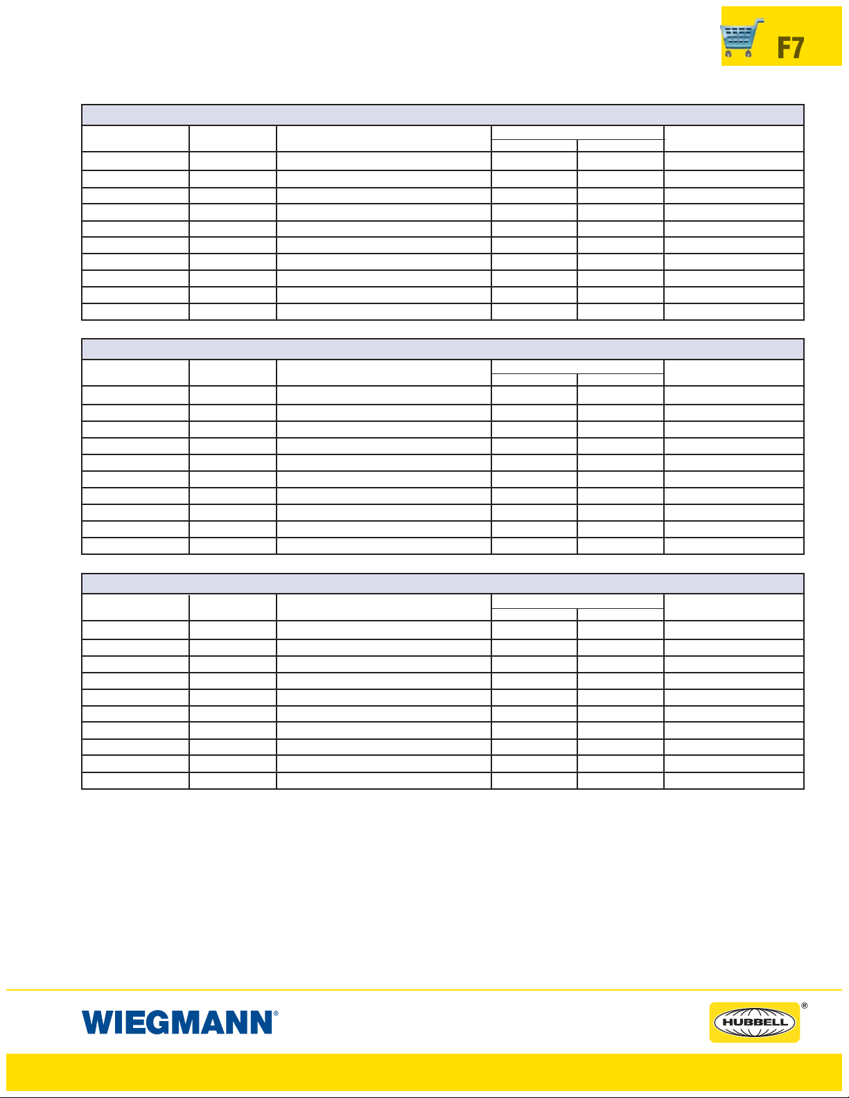
N412CDSSA ULTIMATE SERIES WALLMOUNT DISCONNECTS 316L STAINLESS STEEL
CATALOG BODY/DOOR BACK PANEL CATALOG NUMBER* BACK PANEL
NUMBER STEEL GAUGE
N412202208CDSSA 14/14 20.00 x 22.00 x 8.00 (508 x 559 x 203) NP2020C NP2020CG 18.2 x 18.2 (462 x 462)
N412242208CDSSA 14/14 24.00 x 22.00 x 8.00 (610 x 559 x 203 NP2420C NP2420CG 22.2 x 18.2 (564 x 462)
N412242608CDSSA 14/14 24.00 x 26.00 x 8.00 (610 x 660 x 203 NP2424C NP2424CG 22.2 x 22.2 (564 x 564)
N412302608CDSSA 14/14 30.00 x 26.00 x 8.00 (762 x 660 x 203) NP3024C NP3024CG 28.2 x 22.2 (716 x 564)
N412362608CDSSA 14/14 36.00 x 26.00 x 8.00 (914 x 660 x 203) NP3624C NP3624CG 34.2 x 22.2 (869 x 564)
N412363208CDSSA 14/14 36.00 x 32.00 x 8.00 (914 x 813 x 203) NP3630C NP3630CG 34.2 x 28.2 (869 x 716)
N412423212CDSSA 14/14 42.00 x 32.00 x 12.00 (1067 x 813 x 305) NP4230C NP4230CG 40.2 x 28.2 (1021 x 716)
N412423812CDSSA 14/14 42.00 x 38.00 x 12.00 (1067 x 965 x 305) NP4236C NP4236CG 40.2 x 34.2 (1021 x 869)
N412483812CDSSA 14/14 48.00 x 38.00 x 12.00 (1219 x 965 x 305) NP4836C NP4836CG 46.2 x 34.2 (1173 x 869)
N412603812CDSSA 14/14 60.00 x 38.00 x 12.00 (1524 x 965 x 305) NP6036C NP6036CG 58.2 x 34.2 (1478 x 869)
*Back panels must be ordered separately.
ENCLOSURE SIZE HXWXD
WHITE “G” SIZE A X B
www.hubbell-wiegmann.com
Data Subject To Change Without Notice
Page 8
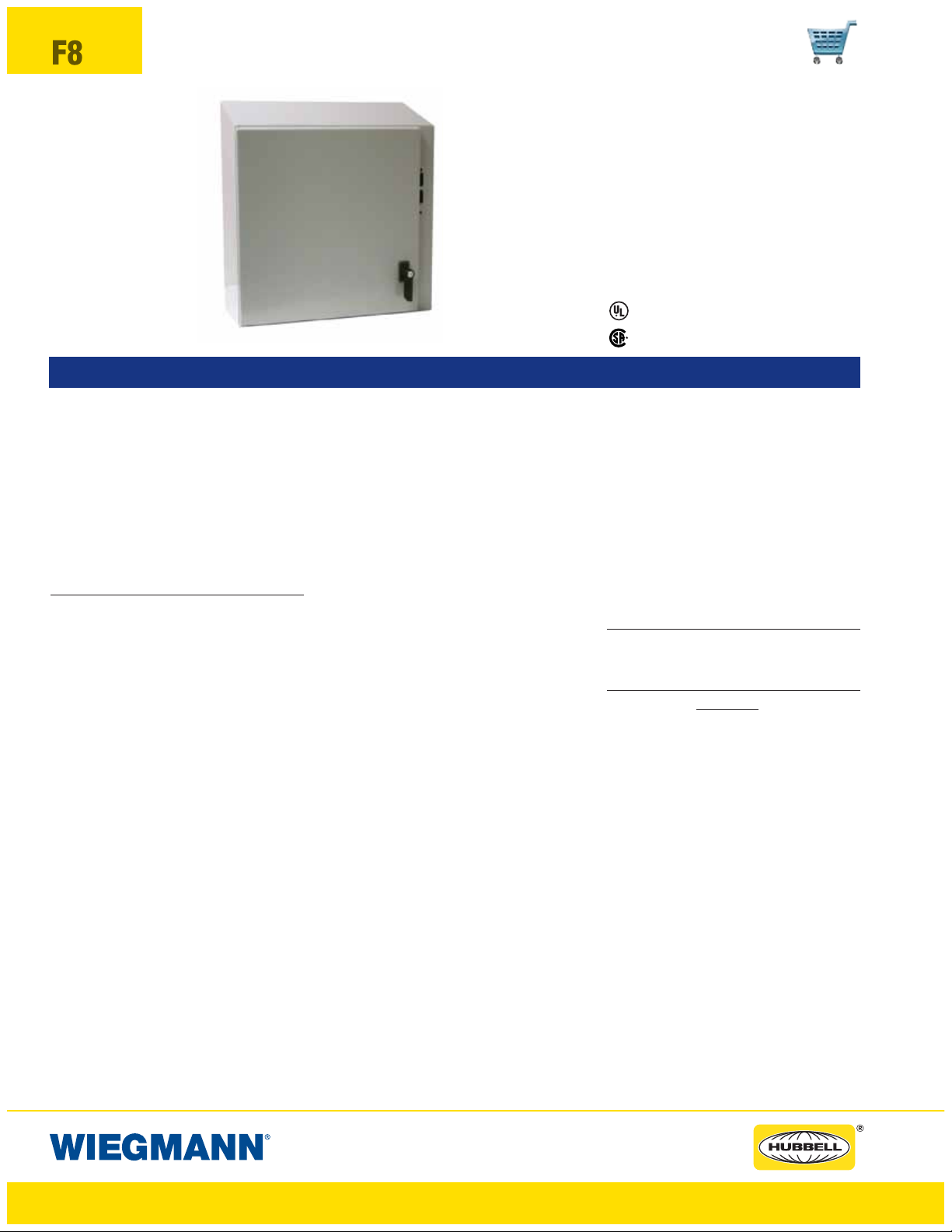
F8
N412-CSTD & N412-CSSSTD SLOPE TOP DISCONNECT
ULTIMATE SERIES ENCLOSURES
Industry Standards
UL 508,
CSA Certified, Types 4, 4x, 12, & 13
NEMA/EEMAC Types 4, 4x, 12, & 13
UL File E64791
Types 4, 4x, 12, & 13
N412242608CSSSTD
FEATURES-SPECIFICATIONS
Applications
Hubbell Wiegmann N412CDTD &
N412CSSSTD Ultimate Series
Disconnects are designed to house
and protect electrical and electronic
components from harsh, dirty environments. For use in installations where
dirt, dust, oil, water or other contaminants are present. Streamlined
styling, latching and attractive
durable finish complement any high
tech electronic equipment.
Construction
• Bodies and doors fabricated from
14 gauge steel (optional 304 also
available)
• Continuously Plasma welded seams
• Increased tub opening for better
access
• 20 Degree sloped top
• Sloped “Top tub flange”
• Concealed hinges
• Doors are interchangeable and
easily removable
• Grounding provisions provided
• 1/4-turn semi-flush oil tight latches
are supplied to hold door securely
closed
• Print pocket is provided
• Doors are sealed with poured-inplace polyurethane gasket
• Mounting holes in rear of enclosure
• Studs for mounting optional back
panel (the Ultimate back panels
have increased in size to accommodate larger foot-print installations)
• Ultimate Accessory Driven
• Door handle and latching hardware
are provided
• Door latching system installed on
door with slotted insert defeater
mechanism to open
• Latching system interlocks with the
disconnect handle for added safety
• 2pt latch system up to 36" in height
and 3pt latch system on enclosures
42" and higher
CSA File LL66078
Fini sh
• ANSI 61 gray polyester powder
inside and out over phosphatized
surfaces
• Stainless: interior = standard commercial finish, ext = standard
grained finish
• Optional back panels are white
polyester powder over phosphatized surfaces
• Optional “G” panels have a con-
ductive finish
Acces sories
• Back panels (reference tables)
• See pages J1-J22
IMPORTANT Ordering Information
• See F2 for disconnect switch, circuit
breakers, operating handle and operating mechanism.
www.hubbell-wiegmann.com
Data Subject To Change Without Notice
Page 9
N412CSTD & N412CSSTD ULTIMATE SERIES ENCLOSURES
NEMA 4X SLOPE TOP SINGLE DOOR DISCONNECT
N412-CSTD ULTIMATE SERIES ENCLOSURES NEMA 4X SLOPE TOP SINGLE DOOR DISCONNECT
CATALOG BODY/DOOR BACK PANEL CATALOG NUMBER* BACK PANEL
NUMBER STEEL GAUGE
N412202208CSTD 14/14 20.00 x 22.00 x 8.00 (508 x 559 x 203) NP2020C NP2020CG 18.2 x 18.2 (462 x 462)
N412242208CSTD 14/14 24.00 x 22.00 x 8.00 (610 x 559 x 203 NP2420C NP2420CG 22.2 x 18.2 (564 x 462)
N412242608CSTD 14/14 24.00 x 26.00 x 8.00 (610 x 660 x 203 NP2424C NP2424CG 22.2 x 22.2 (564 x 564)
N412302608CSTD 14/14 30.00 x 26.00 x 8.00 (762 x 660 x 203) NP3024C NP3024CG 28.2 x 22.2 (716 x 564)
N412363210CSTD 14/14 36.00 x 32.00 x 10.00 (914 x 660 x 203) NP3630C NP3630CG 34.2 x 28.2 (869 x 716)
N412423212CSTD 14/14 42.00 x 32.00 x 12.00 (1067 x 813 x 305) NP4230C NP4230CG 40.2 x 28.2 (1021 x 716)
N412483812CSTD 14/14 48.00 x 38.00 x 12.00 (1219 x 965 x 305) NP4836C NP4836CG 46.2 x 34.2 (1173 x 869)
N412603812CSTD 14/14 60.00 x 38.00 x 12.00 (1524 x 965 x 305) NP6036C NP6036CG 58.2 x 34.2 (1478 x 869)
N412-CSSSTD ULTIMATE SERIES ENCLOSURES NEMA 4X SLOPE TOP SINGLE DOOR DISCONNECT
CATALOG BODY/DOOR BACK PANEL CATALOG NUMBER* BACK PANEL
NUMBER STEEL GAUGE
N412242608CSSSTD 14/14 24.00 x 26.00 x 8.00 (610 x 660 x 203 NP2424C NP2424CG 22.2 x 22.2 (564 x 564)
N412302608CSSSTD 14/14 30.00 x 26.00 x 8.00 (762 x 660 x 203) NP3024C NP3024CG 28.2 x 22.2 (716 x 564)
N412363210CSSSTD 14/14 36.00 x 32.00 x 10.00 (914 x 660 x 203) NP3630C NP3630CG 34.2 x 28.2 (869 x 716)
N412483812CSSSTD 14/14 48.00 x 38.00 x 12.00 (1219 x 965 x 305) NP4836C NP4836CG 46.2 x 34.2 (1173 x 869)
N412603812CSSSTD 14/14 60.00 x 38.00 x 12.00 (1524 x 965 x 305) NP6036C NP6036CG 58.2 x 34.2 (1478 x 869)
*Back panels must be ordered separately.
ENCLOSURE SIZE HXWXD
ENCLOSURE SIZE HXWXD
WHITE “G” SIZEAXB
WHITE “G” SIZEAXB
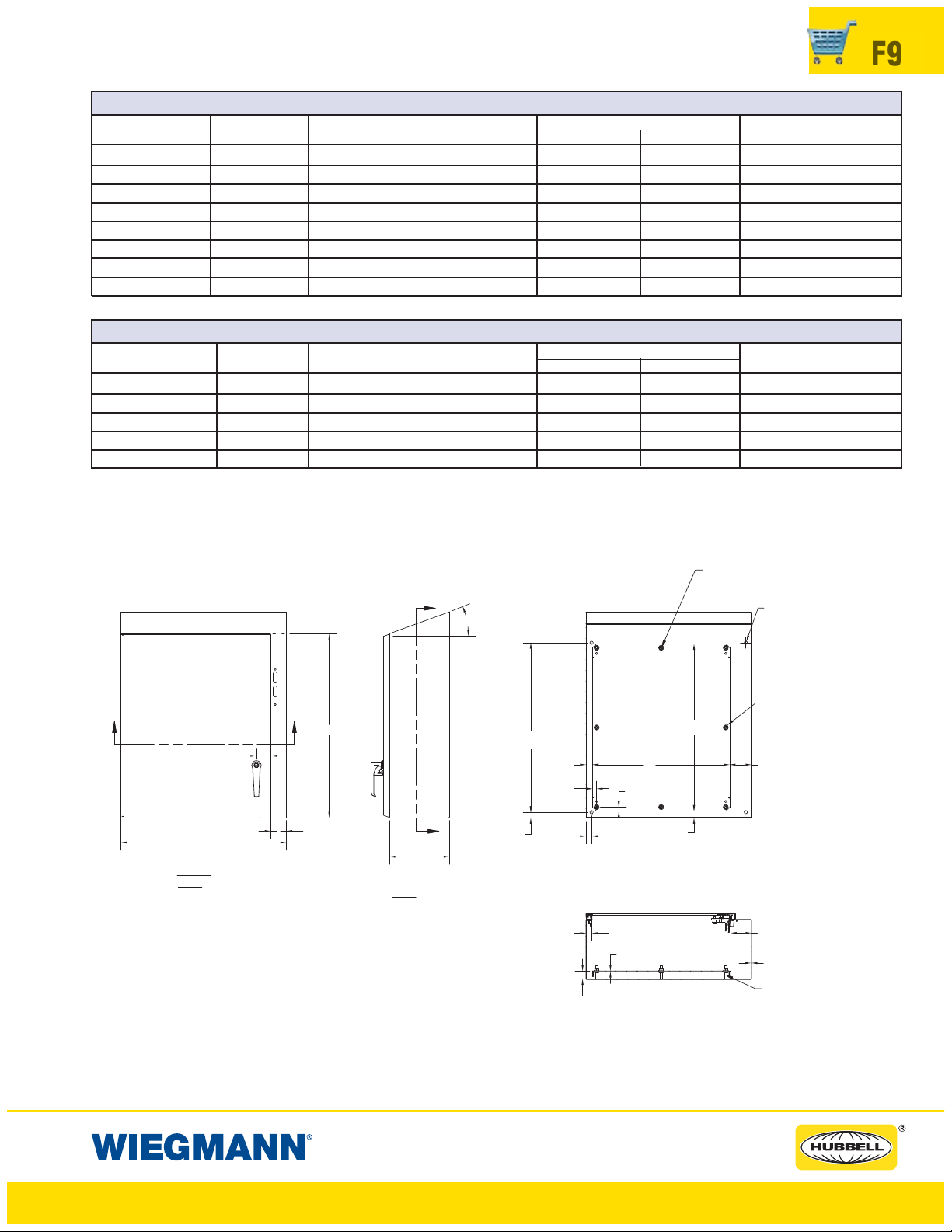
F9
FRONT
VIEW
OMIT TWO MIDDLE
STUDS IF W = LESS THAN 32.00"
A
20°
B
0.900
TYP.
A
H
BB
1.875
W
2.101
RIGHT
VIEW
A
D
0.750
TYP.
E
0.900
0.520
TYP.
0.750
TYP.
1.074
0.520
TYP.
SECTION A-A
0.812
12 GA.
Ø0.438 MOUNTING
PROVISION (4 PL.)
OMIT TWO MIDDLE STUDS
IF H = LESS THAN 31.00"
2.900
2.750
14 GA.
5/16-18 COLLAR
STUDS
SECTION B-B
www.hubbell-wiegmann.com
Data Subject To Change Without Notice
Page 10
F10
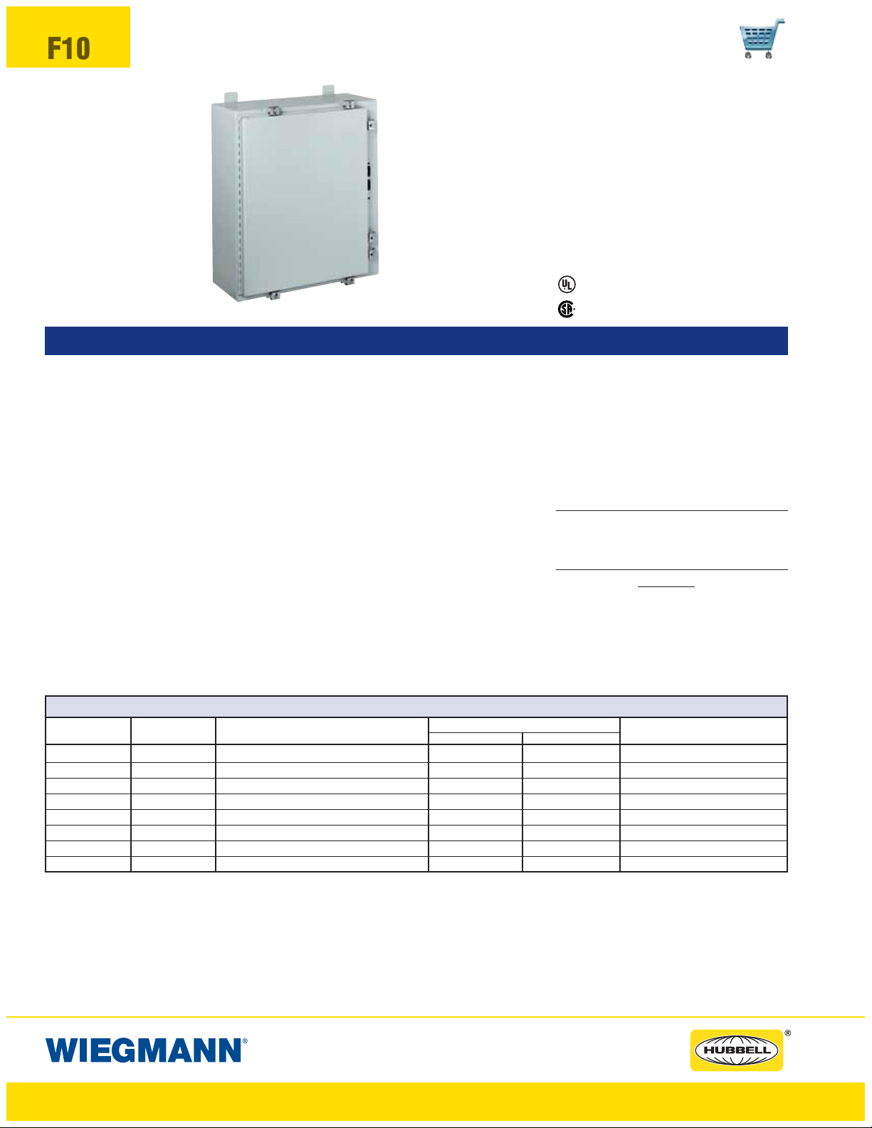
SN4 SERIES ENCLOSURES
NEMA 4 FLANGED SINGLE DOOR DISCONNECT
Industry Standards
UL 508
,Types4,12,&13
CSA Certified, Types 4 & 12
NEMA/EEMAC Types 3,4,12,&13
UL File E64791
SN4242108
CSA File LL66078
FEATURES-SPECIFICATIONS
Construction
• Bodies and doors fabricated from
14 gauge steel
• Plasma welded seams
• Rolled lip around all sides of enclosure opening excludes liquids and
contaminants
• All exterior hardware is stainless
steel
• Stainless steel door clamps are
provided around three sides of
doors for a watertight seal, additional door hardware is not required
• Body and door stiffeners provided
in larger enclosures for extra rigidity
• Doors easily removed by pulling
continuous hinge pin
SN4 SERIES WALL-MOUNT DISCONNECTS
CATALOG BODY/DOOR ENCLOSURE SIZE BACK PANEL CATALOG NUMBER* BACK PANEL
NUMBER STEEL GAUGE H X W X D WHITE “G” SIZE A X B
SN4242108 14/14 24.00x21.38x8.13 (610x543x207) NP2420 NP2420G 21.00x17.00 (533x432)
SN4242508 14/14 24.00x25.38x8.13 (610x645x207) NP2424 NP2424G 21.00x21.00 (533x533)
SN4302508 14/14 30.00x25.38x8.13 (762x645x207) NP3024 NP3024G 27.00x21.00 (686x533)
SN4363108 14/14 36.00x31.38x8.13 (914x797x207) NP3630 NP3630G 33.00x27.00 (838x686)
SN4423112 14/14 42.00x31.38x12.13 (1067x797x308) NP4230 NP4230G 39.00x27.00 (991x686)
SN4423712 14/14 42.00x37.38x12.13 (1067x949x308) NP4236 NP4236G 39.00x33.00 (991x838)
SN4483712** 14/14 48.00x37.38x12.13 (1219x949x308) NP4836 NP4836G 45.00x33.00 (1143x838)
SN4603712** 14/14 60.00x37.38x12.13 (1524x949x308) NP6036 NP6036G 57.00x33.00 (1448x838)
*Back panels must be ordered separately.
**Enclosures are supplied with closed cell neoprene gasket (not foam-in-place).
• Polyurethane poured-in-place gasket
• External mounting feet.
• Collar studs for mounting optional
back panel
• Grounding provisions provided
• Bracket welded to door for attaching disconnect interlock door catch
• Holes provided in body for mounting disconnect operating handle
and operating mechanism. These
enclosures are designed to operate
properly without the use of door
hardware
• Print pocket is provided
Fini sh
• ANSI 61 gray polyester powder
inside and out over phosphatized
surfaces
• Optional back panels are white
polyester powder over phosphatized surfaces
• Optional “G” panels have a con-
ductive finish
Acces sories
• Back panels (reference tables)
• Blank Adapter Plates on page F61
IMPORTANT Ordering Information
• See F2 & F15 for disconnect switch,
circuit breakers, operating handle
and operating mechanism.
www.hubbell-wiegmann.com
Data Subject To Change Without Notice
Page 11
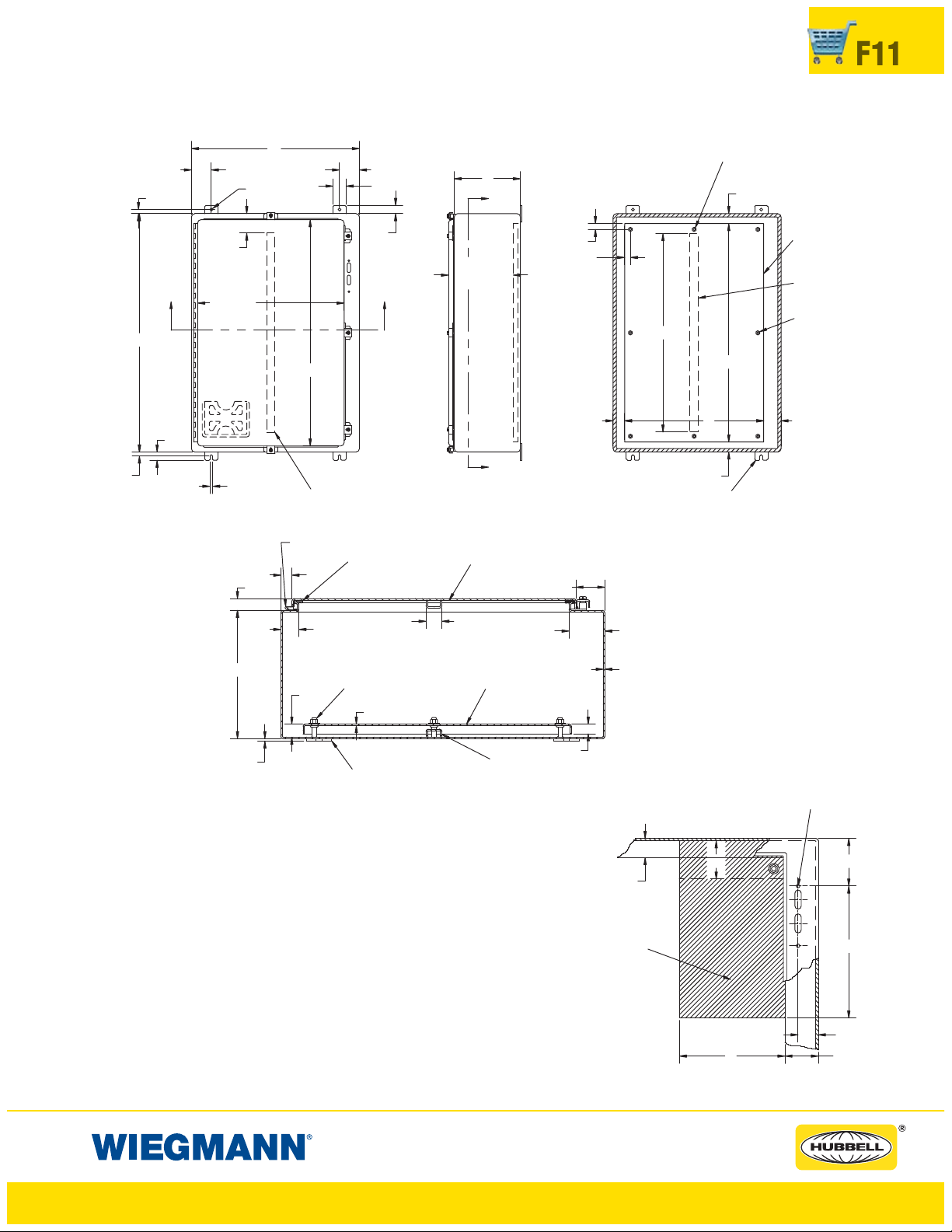
SN4 SERIES ENCLOSURES
NEMA 4 FLANGED SINGLE DOOR DISCONNECT
F11
0.63
W
1.25
3.00
2.00
D
Y
0.88
0.88
D-0.28
X
H-6.00
Y
MOUNTING FEET
3.00
3.00
TYP
W-3.13
Ø0.44
H-1.63
DOOR STIFFENER
IF H = 42.00"OR
MORE
0.63
X
H
1.25
0.44
OMIT TWO MIDDLE STUDS
IF W = LESS THAN 32.00"
1.50
A
B1.75 2.62
1.50
PANEL
(Order
Separately)
STIFFENER
SEE Page F27
OMIT TWO MIDDLE
STUDS IF H = LESS
THAN 31.00"
SECTION Y-Y
CONTINUOUS
HINGE
0.63
0.88
1.31
D
1.09
GASKET
3/8-16 COLLAR
STUD
12 GA.
DOOR
STIFFENER
1.25 TYP
PANEL
(ORDER SEPARATELY)
2.50
14 GA.
2.75
Notes:
1. Large print pocket (8" x 10") is
provided in each enclosure.
2. Panelsaremadefrom12Ga. steel.
3. Panels have flanges along all sides
when either dimension exceeds 17".
4. The number of door clamps is
dependent on size of enclosure.
Clamps are furnished along three
sides of door.
5. See page F27 for Stiffener Location.
0.19
MOUNTING
FEET
SECTION X-X
Space Occupied by Disconnect
E = 8.63 when Depth = 8.00
E = 11.62 when Depth = 12.00
WB = Wiring Space
See pages F16-F22 for various brands of disconnects
for “F”, “G”,&“WB” dimensions.
Disconnects will occupy space on panel shown by dimensions
“E”, “F”,&“G”. Wiring space “WB” is available when disconnect
is installed in the enclosure.
Refer to National Electrical Code article 430-10(b) for wiring
space required for line side conductors to be connected to disconnect.
Verify your application to determine if wiring space is adequate.
BODY
STIFFENER
0.75
1.50
THIS SPACE IS OCCUPIED
BY DISCONNECT SWITCH
AND FUSE CLIP (IF USED)
OR CIRCUIT BREAKER.
www.hubbell-wiegmann.com
Data Subject To Change Without Notice
TOP HOLE IN
R.H. FLANGE
W
G
E
F
1.59
2.75
Page 12
F12
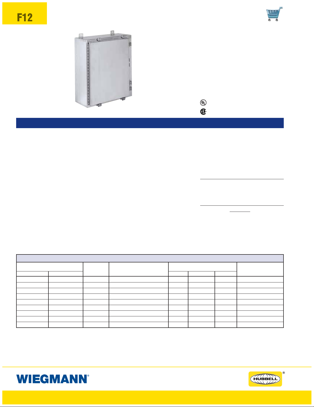
SSN4X SERIES ENCLOSURES
NEMA 4X FLANGED SINGLE DOOR DISCONNECT
Industry Standards
UL 508,
Types 4, 4X, 12, & 13
CSA Certified, Types 4 & 12
NEMA/EEMAC Types 4, 4X, 12, & 13
UL File E64791
SSN4X242108
CSA File LL66078
FEATURES-SPECIFICATIONS
Construction
• Bodies and doors fabricated from
14 gauge 304 stainless steel
• Continuously welded seams ground
smooth
• Rolled lip around all sides of enclosure opening excludes liquids and
contaminants
• All exterior hardware is stainless
steel
• All interior and exterior parts of
stainless steel enclosures are stainless steel except for print pocket
• Stainless steel door clamps are
provided around three sides of
doors for a watertight seal, additional door hardware is not required
• Body and door stiffeners provided
in larger enclosures for extra rigidity
• Doors removed by pulling stainless
steel continuous hinge pin
• Polyurethane poured-in-place gasket
• External mounting feet
• Collar studs for mounting optional
back panel
• Grounding provisions provided
• Bracket welded to door for attaching disconnect interlock door catch
• Holes are provided in body for
mounting disconnect operating
handle and operating mechanism.
These enclosures are designed to
operate properly without the use of
door hardware
Fini sh
• Enclosures have a grained finish on
all external surfaces
• Optional back panels are white
polyester powder over phosphatized
surfaces
• Optional “G” panels have a con-
ductive finish
Acces sories
• Back panels (reference tables)
• Blank Adapter Plates are on page
F61
IMPORTANT Ordering Information
• See F2 & F15 for disconnect switch,
circuit breakers, operating handle
and operating mechanism.
• Print pocket is provided
SSN4X SERIES STAINLESS WALL-MOUNT DISCONNECTS
CATALO G NU MB E R BODY/DOOR ENCLOSURE SIZE BACK PANEL CATALOG NUMBER* BACK PANEL
304 316L WHITE 304 SS “G”
SSN4X242108 SSN4X242108A 14/14 24.00x21.38x8.13 (610x543x207) NP2420 NP2420SS NP2420G 21.00x17.00 (533x432)
SSN4X242508 SSN4X242508A 14/14 24.00x25.38x8.13 (610x645x207) NP2424 NP2424SS NP2424G 21.00x21.00 (533x533)
SSN4X302508 SSN4X302508A 14/14 30.00x25.38x8.13 (762x645x207) NP3024 NP3024SS NP3024G 27.00x21.00 (686x533)
SSN4X362508 SSN4X362508A 14/14 36.00x25.38x8.13 (914x645x207) NP3624 NP3624SS NP3624G 33.00x21.00 (838x533)
SSN4X363108 SSN4X363108A 14/14 36.00x31.38x8.13 (914x797x207) NP3630 NP3630SS NP3630G 33.00x27.00 (838x686)
SSN4X423112 SSN4X423112A 14/14 42.00x31.38x12.13 (1067x797x308) NP4230 NP4230SS NP4230G 39.00x27.00 (991x686)
SSN4X423712 SSN4X423712A 14/14 42.00x37.38x12.13 (1067x949x308) NP4236 NP4236SS NP4236G 39.00x33.00 (991x838)
SSN4X483712 SSN4X483712A 14/14 48.00x37.38x12.13 (1219x949x308) NP4836 NP4836SS NP4836G 45.00x33.00 (1143x838)
SSN4X603712** SSN4X603712A** 14/14 60.00x37.38x12.13 (1524x949x308) NP6036 NP6036SS NP6036G 57.00x33.00 (1448x838)
*Back panels must be ordered separately.
**Enclosures are supplied with closed cell neoprene gasket (not foam-in-place).
STEEL GAUGE H X W X D SIZ E A X B
www.hubbell-wiegmann.com
Data Subject To Change Without Notice
Page 13
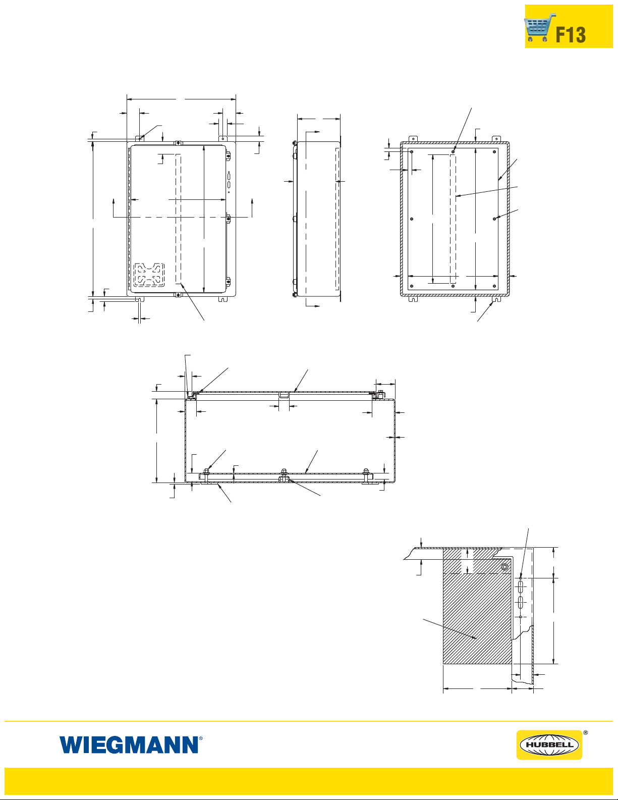
SSN4X SERIES ENCLOSURES
NEMA 4X FLANGED SINGLE DOOR DISCONNECT
F13
0.63
W
1.25
3.00
2.00
D
Y
0.88
0.88
D-0.28
X
H-6.00
Y
MOUNTING FEET
3.00
3.00
TYP
W-3.13
Ø0.44
H-1.63
DOOR STIFFENER
IF H = 42.00"OR
MORE
0.63
X
H
1.25
0.44
OMIT TWO MIDDLE STUDS
IF W = LESS THAN 32.00"
1.50
A
B1.75 2.62
1.50
PA NE L
(Order
Separately)
STIFFENER
SEE Page F27
OMIT TWO MIDDLE
STUDS IF H = LESS
THAN 31.00"
SECTION Y-Y
CONTINUOUS
HINGE
0.63
0.88
1.31
D
1.09
GASKET
3/8-16 COLLAR
STUD
12 GA.
DOOR
STIFFENER
1.25 TYP
PANEL
(ORDER SEPARATELY)
2.50
14 GA.
2.75
Notes:
1. Large print pocket (8" x 10") is
provided in each enclosure.
2. Panels are made from 12 Ga. steel.
3. Panels have flanges along all sides
when either dimension exceeds 17".
4. The number of door clamps is
dependent on size of enclosure.
Clamps are furnished along three
sides of door.
5. See page F27 for Stiffener Location.
0.19
MOUNTING
FEET
SECTION X-X
Space Occupied by Disconnect
E = 8.63 when Depth = 8.00
E = 11.62whenDepth= 12.00
WB = Wiring Space
See pages F16-F22 for various brands of disconnects
for “F”, “G”,&“WB” dimensions.
Disconnects will occupy space on panel shown by dimensions
“E”, “F”,&“G”. Wiring space “WB” is available when disconnect
is installed in the enclosure.
Refer to National Electrical Code article 430-10(b) for wiring
space required for line side conductors to be connected to disconnect.
Verify your application to determine if wiring space is adequate.
BODY
STIFFENER
0.75
1.50
THIS SPACE IS OCCUPIED
BY DISCONNECT SWITCH
AND FUSE CLIP (IF USED)
OR CIRCUIT BREAKER.
www.hubbell-wiegmann.com
Data Subject To Change Without Notice
TOPHOLEIN
R.H. FLANGE
W
G
E
F
1.59
2.75
Page 14
F14
ABN12, SDN12, SDN12PL, N412CD, N412CSTD, & N412CSSSTD SERIES
ENCLOSURES NEMA 12 FLANGED SINGLE DOOR DISCONNECT
DISCONNECT ORDERING INFORMATION
When ordering wall-mounted disconnects from the various manufacturers, be sure to order
all of the necessary items. Each company has a different system, so care is required. Order
the following items from the disconnect manufacturer.
Allen-Bradley
• 1494V disconnect switches with flange-mount
variable depth operating mechanisms and
1494V flange-mounted variable depth operating
mechanisms for circuit breakers
• 140U flexible cable operating mechanisms and
140U molded case circuit breakers
• 1494C cable-operated disconnect switches with
flange-mount handles
• 194RC cable-operated flange-mount handles for
use with the NFPA 79 compliant 194R IEC rotary
disconnect switches
Allen-Bradley 1494V-R1, -R2 and -W2 operating
handles and Allen-Bradley 1494F disconnect
devices or 1494D circuit breaker operators will
NOT fit these enclosures.
When using a Bulletin 1494V disconnect
order:
* 1. A disconnect switch with operating
mechanism (Bulletin 1494V)
* 2. Bulletin 1494-H1 operating handle (Use
Bulletin 1494-H2 for enclosure catalog
number SDN12603812A)
* 3. A connecting rod [Bulletin 1494V-RA1 for
8.00" (203mm) and 10.00" (254mm) deep
enclosures; Bulletin 1494V-RA2 for 12.00"
(305mm) and 16.00" (406mm) deep
enclosures; two of Bulletin 1494-RB2 for
400 amp or 600 amp switch in a
SDN12603812A]
switch,
* 4. A trailer fuse block kit, if required (Bulletin 1494V)
* 5. A fuse clip kit, if required
6. Line and load connectors, if required
** 7. Door hardware (Bulletin 1494V-L1 for
2-point latching or Bulletin 1494V-L1
and 1494V-L2 for 3-point door latching)
When using a Bulletin 1494V circuit breaker
operating mechanism, order:
1. A circuit breaker (C-H)
2. A circuit breaker operating mechanism
(Bulletin 1494V)
3. An operating handle (Bulletin 1494V-H11)
4. A connecting rod [Bulletin 1494V-RA1 for
8.00" (203mm) and 10.00" (254mm) deep
enclosures or Bulletin 1494V-RA2 for 12.00"
(305mm) and 16.00" (406mm) deep enclosures]
** 5. Door hardware (Bulletin 1494V-L1 for
2-point latching or Bulletin 1494V-L1
and 1494V-L2 for 3-point door latching)
Allen-Bradley 1494 F Series See F23-F26
ABB Controls
When using a disconnect switch, order:
1. A flange operated switch (fusible or non-fusible)
2. A shaft [DSFHS-12 for 8.00” (203mm),
10.00" (254mm) and 12.00" (305mm) deep
enclosures or DSFHS-17 for 16.00”
(406mm) deep enclosures]
3. A handle (DSFGN-HS12)
** 4. Door hardware (FH-DHK for 2-point latching
or FH-DHK and FH-3RL for 3-point latching)
When using a circuit breaker, order:
1. A circuit breaker (ABB)
* 2. An operating mechanism
* 3. A shaft [FHS-12 for 8.00” (203mm), 10.00"
(254mm) and 12.00" (305mm) deep enclosures or FHS-17 for 16.00” (406mm) deep
enclosures]
* 4. Handle mechanism (FHN-HS12)
** 5. Door hardware (FH-DHK for 2-point latching
or FH-DHK and FH-3RL for 3-point latching)
Eaton Cutler-Hammer
When using a Type C361 disconnect switch, order:
* 1. A disconnect switch with an operating
mechanism
* 2. An operating handle (C361H1 or C361H3)
** 3. Door hardware (C361KJ4 or C361KJ6 for
2-point latching, C361KJ4 or C361KJ6 and
C361KR for 3-point latching)
When using a Type C371 circuit breaker
operating mechanism with a C-H circuit
breaker, order:
1. A circuit breaker
* 2. An operating mechanism
* 3. An operating handle
** 4. Door hardware (C361KJ4 or C361KJ6 for
2-point latching, C361KJ4 or C361KJ6 and
C361KR for 3-point latching)
When using a C-H circuit breaker with a Flex
™
Shaft
handle mechanism, order:
1. A circuit breaker
2. A complete Flex Shaft
** 3. Door hardware (C361KJ4 or C361KJ6 for
2-point latching, C361KJ4 or C361KJ6 and
C361KR for 3-point latching)
™
handle mechanism
General Electric
When using a disconnect switch, order:
1. A disconnect switch (Type QMR or QMW)
2. A fuse clip kit or no-fuse kit
3. A flange handle (STDA1 or STDA2)
4. A variable depth operating mechanism
** 5. Door hardware (TDV1 for 2-point latching
or TDV1 and TDV3 for 3-point latching)
When using a circuit breaker with a Spectra Flex
cable operator, order:
1. A circuit breaker
2. A flange-mounted handle mechanism
3. A breaker-mounted mechanism
4. An operating cable
** 5. Door hardware (TDV1 for 2-point latching
or TDV1 and TDV3 for 3-point latching)
When using a circuit breaker, order:
1. A circuit breaker
2. A flange handle (STDA1 or STDA2)
3. A variable depth operating mechanism
** 4. Door hardware (TDV1 for 2-point latching
or TDV1 and TDV3 for 3-point latching)
Siemens I-T-E Max-Flex
When using a disconnect switch, order:
1. A basic switch (right-hand)
2. A fuse or no-fuse kit
* 3. FHOHS flange-mounted handle
*4. Switchoperator
* 5. Cable, 36"
** 6. Door hardware (DKR2 for 2-point latching
or DKR3 for 3-point latching)
NOTE: Some I-T-E fixed depth switch operators can be
used. Contact Hubbell/Wiegmann for more information.
When using a circuit breaker, order:
1. A circuit breaker
2. Pressure wire connectors
* 3. FHOH flange-mounted handle (Use
FHOHN for enclosure catalog number
SDN12603812A)
™
Siemens ITE Max-Flex
™
(cont.)
* 4. A circuit breaker operator mechanism
* 5. An operating cable (standard 36.00" for 125
amp to 600 amp circuit breakers, and
48.00" for 800 amp to 1200 amp circuit
breakers)
** 6. Door hardware (DKR2 for 2-point latching or
DKR2 for 3-point latching)
Schneider Square D
®
When using a Class 9422 disconnect switch, order:
* 1. A disconnect switch with operating
mechanism (Class 9422)
* 2. A handle mechanism (Class 9422 Type A-1)
** 3. A door closing mechanism (Class 9423
Type M4 for 2-point latching, or Class 9423
Type M9 or M4 and Class 9423 Type M3 for
3-point latching)
When using a circuit breaker, order:
1. A circuit breaker (Schneider Square D
* 2. An operating mechanism (Class 9422)
* 3. A handle mechanism (Class 9422 Type A-1)
** 4. A door closing mechanism (Class 9423
Type M4 for 2-point latching, or Class 9423
Type M9 or M4 and Class 9423 Type M3
for 3-point latching)
When using a Class 9422 Type “T” disconnect
switch with a cable mechanism, order:
1. A disconnect switch with operating
mechanism (Class 9422, Type T)
2. A handle mechanism (Class 9422, Type A-1)
3. A cable mechanism (Class 9422, CFT_O)
3-, 5-, or 10-foot
** 4. A door closing mechanism (Class 9423
Type M4 for 2-point latching, or Class 9423
Type M9 or M4 and Class 9423 Type M3
for 3-point latching)
When using a circuit breaker with a cable
™
mechanism, order:
1. A circuit breaker (Schneider Square D
2. A handle mechanism (Class 9422, Type A-1)
3. A cable mechanism (Class 9422, CFT_O)
3-, 5-, or 10-foot
** 4. A door closing mechanism (Class 9423
Type M4 for 2-point latching, or Class 9423
Type M9 or M4 and Class 9423 Type M3
for 3-point latching)
* Items available from disconnect manufacturer as
complete kits.
** Enclosure “A” dimension less than 40.00" (1016mm)
requires a 2-point door closing mechanism.
Enclosures with an “A” dimension of 40.00" or more
require a 3-point latching mechanism.
PLEASE NOTE:
1. Operator adapter plates are not required with
enclosures on page F2-F13.
2. Various other switch accessories and circuit
breaker accessories are available from disconnect manufacturers. The information is subject
to change without notice. Please contact
Hubbell/Wiegmann or the disconnect manufacturer if there are further questions.
3. The “Space Occupied” tables (pages F16-F22)
are based upon information supplied by disconnect manufacturers. Hubbell/Wiegmann
does not assume responsibility for the accuracy
of these dimensions.
4. Check to make certain enclosure size is adequate for disconnect mechanisms and wire
bend space both above line lugs and below
load lugs.
®
)
®
)
www.hubbell-wiegmann.com
Data Subject To Change Without Notice
Page 15

SN4 & SSN4X SERIES ENCLOSURES
NEMA 4 FLANGED SINGLE DOOR DISCONNECT
DISCONNECT ORDERING INFORMATION
When ordering wall-mounted disconnects from the various
manufacturers, be sure to order all of the necessary items.
Each company has a different system, so care is required.
Order the following items from the disconnect manufacturer.
F15
Use a Type 4 & 4X disconnect operating handle on the
enclosure flange to provide corrosion resistance and maintain enclosure rating.
Allen-Bradley
When using a Bulletin 1494V disconnect switch, order:
1. A disconnect switch with operating
mechanism (Bulletin 1494V)
2. An operating handle (Bulletin
1494V-W1)
3. A connecting rod [Bulletin 1494VRA1 for 8.00" (203mm) deep enclosures; Bulletin 1494V-RA2 for
12.00" (305mm) deep enclosures]
4. A trailer fuse block kit, if required
(Bulletin 1494V)
5. A fuse clip kit, if required
6. Line and load connectors, if
required
When using a Bulletin 1494V circuit
breaker operating mechanism, order:
1. A circuit breaker (C-H)
2. A circuit breaker operating mechanism (Bulletin 1494V)
3. An operating handle (Bulletin
494V-W11)
4. A connecting rod [Bulletin 1494VRA1 for 8.00" (203mm) deep enclosures; Bulletin 1494V-RA2 for
12.00" (305mm) deep enclosures]
ABB Controls
When using a disconnect switch,
order:
1. A flange operated switch (fusible
or non-fusible)
2. A shaft [DSFHS-12]
3. A handle (DSFHN-HS4)
When using a circuit breaker, order:
1. A circuit breaker (ABB)
2. An operating mechanism
3. A shaft [FHS-12]
4. A handle (FHN-HS4)
Eaton Cutler-Hammer
When using a Type C361 disconnect
switch, order:
1. A disconnect switch with an
operating mechanism
2. An operating handle (C361H2 or
C361H4)
When using a Type C371 circuit breaker
operating mechanism with a C-H
circuit breaker, order:
1. A circuit breaker
2. An operating mechanism
3. An operating handle (C371H2 or
C371H4)
When using a C-H circuit breaker
with a Type 4/4X Flex Shaft
™
handle
mechanism, order:
1. A circuit breaker
2. A complete Flex Shaft
™
handle
mechanism
General Electric
When using a disconnect switch,
order:
1. A disconnect switch (Type QMR
or QMW)
2. A fuse clip kit or no-fuse kit
3. A flange handle (STDA1X)
4. A variable depth operating mechanism
When using a circuit breaker, order:
1. A circuit breaker
2. A flange handle (STDA1X)
3. A variable depth operating mechanism
When using a circuit breaker with a
Spectra Flex
™
cable operator, order:
1. A circuit breaker
2. A flange-mounted handle mechanism
3. A breaker-mounted mechanism
4. An operating cable
PLEASE NOTE:
1. Operator adapter plates and door hardware are not required with enclosures on page F2-F13.
2. Various other switch accessories and circuit breaker accessories are available from disconnect manufacturers. The above information is subject to change without notice. Please
contact Hubbell-Wiegmann or the disconnect manufacturer if there are further questions.
3. The “Space Occupied” tables (pages F16-F22) are based upon information supplied by
disconnect manufacturers. Hubbell-Wiegmann does not assume responsibility for the accuracy of these dimensions.
* Items available from disconnect manufacturer as complete kits.
Siemens ITE Max-Flex
™
When using a disconnect switch,
order:
1. A basic switch (right-hand)
2.Afuseorno-fusekit
3. A flange-mounted handle (FHOHS4)
4. Switch operator
5. Cable, 36.00"
When using a circuit breaker, order:
1. A circuit breaker
2. Pressure wire connectors
3. A flange-mounted handle (FH0H4)
4. A circuit breaker operator mechanism
5. An operating cable (standard 36.00")
Schneider Square D
®
When using a Class 9422 disconnect
switch, order:
1. A disconnect switch with operating
mechanism (Class 9422)
2. A handle mechanism (Class 9422
Type A-2 or A-1)
When using a circuit breaker, order:
1. A circuit breaker (Schneider Square D
2. An operating mechanism (Class
9422)
3. A handle mechanism (Class 9422
Type A-2 or A-1)
When using a Class 9422 Type “T”
disconnect switch with a cable mechanism, order:
1. A disconnect switch with operating
mechanism (Class 9422, Type T)
2. A handle mechanism (Class 9422
Type A-1)
3. A cable mechanism (Class 9422
CFT_O) 3-, 5-, or 10-foot
When using a circuit breaker with a
cable mechanism, order:
1. A circuit breaker (Schneider
Square D
®
)
2. A handle mechanism (Class 9422
Type A-1)
3. A cable mechanism (Class 9422
CFT_O) 3-, 5-, or 10-foot
®
)
www.hubbell-wiegmann.com
Data Subject To Change Without Notice
Page 16
F16
ABN12, SDN12, SDN12PL, N412CD,
N412CSTD, N412CSSSTD, SN4 & SSN4X SERIES ENCLOSURES
DISCONNECT SPACE OCCUPIED & AVAILABLE WIRING SPACE INFORMATION
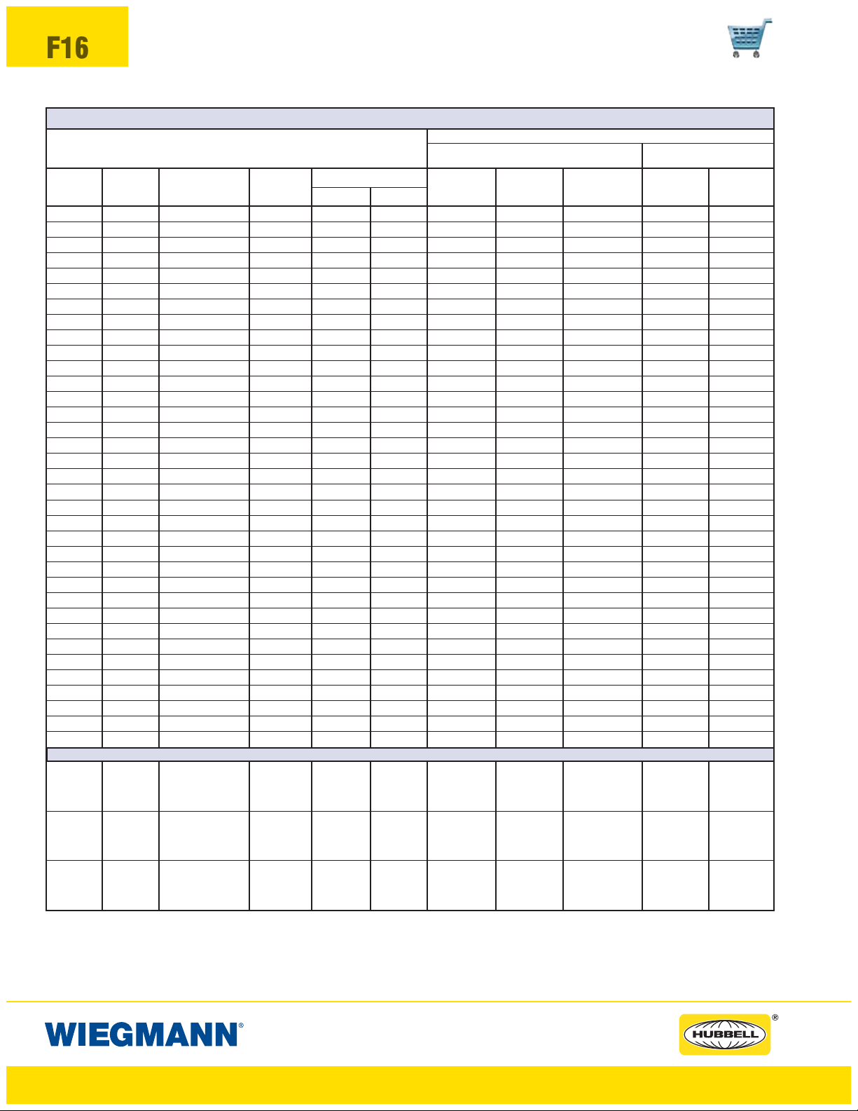
ALLEN-BRADLEY BULLETIN 1494V DISCONNECTS
ABN12, SDN12, SDN12PL, N412CD, SN4 & SSN4X WALL-MOUNTS
N412CSTD & N412CSSSTD (PAGES F2-F9) (PAGES F10-F13)
TYPE AMP FUSE FUSE
NUMBER RATING CLIP CLASS
DS30 30A No fuse — 3.88 6.62 2.78 5.15 9.66 6.66 9.66
DS30 30A 30A-250V H, K, R 5.25 6.62 2.78 5.15 9.66 6.66 9.66
DS30 30A 30A-600V H, K, R 8.00 6.62 2.78 5.15 9.66 6.66 9.66
DS30 30A 30A-600V J 5.25 6.62 2.78 5.15 9.66 6.66 9.66
DS30 30A 60A-250V H, K 6.00 6.62 2.78 5.15 9.66 6.66 9.66
DS30 30A 60A-600V H, K 8.50 6.62 2.78 5.15 9.66 6.66 9.66
DS30 30A 60A-600V J 5.38 6.62 2.78 5.15 9.66 6.66 9.66
DS60 60A No fuse — 3.88 6.62 2.01 4.35 8.89 5.89 8.89
DS60 60A 60A-250V H, K, R 6.00 6.62 2.01 4.35 8.89 5.89 8.89
DS60 60A 60A-600V H, K, R 8.50 6.62 2.01 4.35 8.89 5.89 8.89
DS60 60A 60A-600V J 5.38 6.62 2.01 4.35 8.89 5.89 8.89
DS60 60A 30A-600V H, K, R 8.00 6.62 2.01 4.35 8.89 5.89 8.89
DS60 60A 100A-250V H, K 8.50 6.62 2.01 4.35 8.89 5.89 8.89
DS60 60A 100A-600V H, K 10.50 6.62 2.01 4.35 8.89 5.89 8.89
DS60 60A 100A-600V J 7.25 6.62 2.01 4.35 8.89 5.89 8.89
DS100 100A*** No fuse — 3.88 6.62 — 4.17 8.67 5.70 8.70
DS100 100A*** 100A-250V H, K, R 8.12 6.62 — 4.17 8.67 5.70 8.70
DS100 100A*** 100A-600V H, K, R 10.12 6.62 — 4.17 8.67 5.70 8.70
DS100 100A*** 100A-600V J 6.88 6.62 — 4.17 8.67 5.70 8.70
DS100 100A*** 60A-600V H, K, R 10.12 6.62 — 4.17 8.67 5.70 8.70
DS100 100A*** 60A-600V J 8.88 6.62 — 4.17 8.67 5.70 8.70
DS200 200A*** No fuse — 4.75 7.88 — — 8.12 — 8.12
DS200 200A*** 200A-250V H, K, R 10.88 7.88 — — 8.12 — 8.12
DS200 200A*** 200A-600V H, K, R 13.38 7.88 — — 8.12 — 8.12
DS200 200A*** 200A-600V J 9.50 7.88 — — 8.12 — 8.12
DS200 200A*** 100A-600V H, K, R 12.00 7.88 — — 8.12 — 8.12
DS200 200A*** 100A-600V J 8.75 7.88 — — 8.12 — 8.12
DS400 400A** No fuse — 10.75 10.88 — — — — —
DS400 400A** 400A-250V H, K, R 16.12 10.88 — — — — —
DS400 400A** 400A-600V H, K, R 19.12 10.88 — — — — —
DS400 400A** 400A-600V J 14.62 10.88 — — — — —
DS600 600A No fuse — 10.75 10.88 — — — — —
DS600 600A**** 600A-250V H, R 10.75 10.88 — — — — —
DS600 600A**** 600A-600V H, R 10.75 10.88 — — — — —
DS600 600A 600A-600V J 17.59 10.88 — — — — —
ALLEN-BRADLEY BULLETIN 1494V CIRCUIT BREAKERS
SPACE OCCUPIED
FG*
WHEN WHEN WHEN WHEN WHEN
D=8.00 D=10.00 D=12 OR 16 D=8.00 D=12.00
WB WB WB WB WB
WIRE BEND SPACE “WB” ABOVE DISCONNECT
M40 15A-150A
M50 70A-250A
M60 100A-400A
* Does not include space for optional auxiliary switch.
** The 400 amp disconnect switch and the 600 amp disconnect switch will only fit catalog number SDN12603812A
(see page F4). Wire bend space of 12.13" is provided above disconnect when installed.
*** Series B
**** ”F” and “G” do not include separately mounted fuse blocks.
EHD, FD, FDB
FDC, HFD, HMCP,
Circuit Breakers
HJD, HMCP
Circuit Breakers
HKD, HMCP
— 5.00 4.50 4.25 6.62 11.12 8.12 11.12
— 9.75 4.75 — — 10.62 — 10.62JD, JDB, JDC,
— 9.69 6.12 — — 10.50 — 10.50KD, KDB, KDC,
www.hubbell-wiegmann.com
Data Subject To Change Without Notice
Page 17
ABN12, SDN12, SDN12PL, N412CD,
N412CSTD, N412CSSSTD, SN4 & SSN4X SERIES ENCLOSURES
DISCONNECT SPACE OCCUPIED & AVAILABLE WIRING SPACE INFORMATION
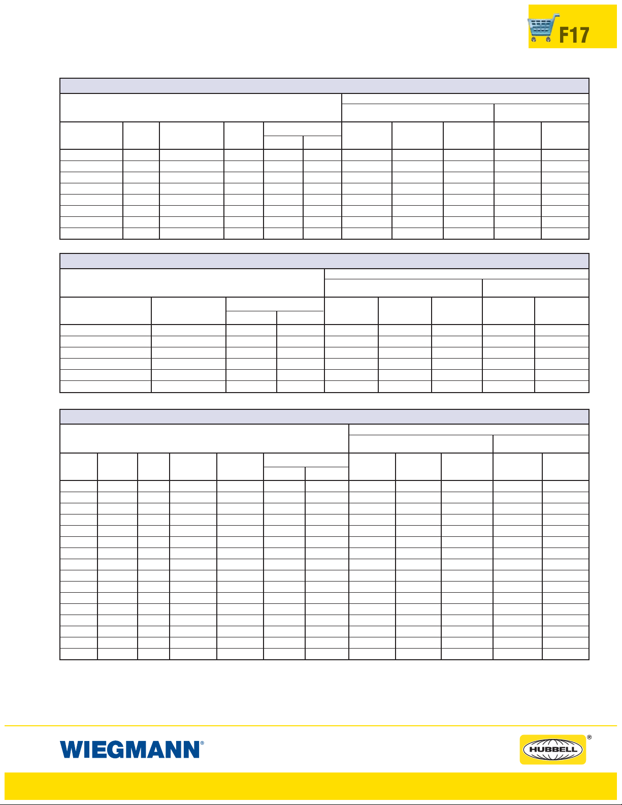
ABB CONTROLS DISCONNECT SWITCHES WITH FLANGE-MOUNTED OPERATORS
K2FHD-M
ABN12, SDN12, SDN12PL, N412CD, SN4 & SSN4X WALL-MOUNTS
N412CSTD & N412CSSSTD (PAGES F2-F9) (PAGES F10-F13)
TYPE AMP FUSE FUSE
NUMBER RATING CLIP CLASS
OETL-NF30-F 40A No fuse — 4.45 3.78 6.41 8.75 13.28 10.28 13.28
OETL-NF60-F 80A No fuse — 4.86 3.78 6.22 8.56 13.09 10.09 13.09
OETL-NF100-F 100A No fuse — 4.86 4.78 5.66 8.00 12.53 9.53 12.53
OETL-NF175-F 175A No fuse — 7.30 6.49 — 5.75 10.28 7.28 10.28
OETL-NF200-F 200A No fuse — 7.36 7.28 — 5.75 10.28 7.28 10.28
OESA-F30J6-F 30A 30A-600V J 4.28 6.58 4.73 7.07 11.61 8.61 11.61
OESA-F60J6-F 60A 60A-600V J 4.28 6.26 4.73 7.07 11.61 8.61 11.61
OESA-F100J6-F 100A 100A-600V J 6.54 7.65 4.30 6.64 11.17 8.17 11.17
ABB CONTROLS CIRCUIT BREAKERS WITH FLANGE-MOUNTED OPERATORS
MECHANISM AMP RATING
K2FHD-M 100A 6.92 3.94 3.39 5.73 10.26 7.26 10.26
K3FHD-M 150A-225A 5.98 4.23 — — 5.56 5.56 5.56
K4FHD-M 250A 7.44 4.23 — — 3.95 — 3.95
K5FHD-M 400A 9.71 5.62 — — — — —
K5FHD-M 600A/800A 8.28 11.26 — — — — —
K5FHD-M 800A 10.11 11.26 — — — — —
SPACE OCCUPIED
FG
SPACE OCCUPIED
FG
WHEN WHEN WHEN WHEN WHEN
D=8.00 D=10.00 D=12 OR 16 D=8.00 D=12.00
WB WB WB WB WB
ABN12, SDN12, SDN12PL, N412CD, SN4 & SSN4X WALL-MOUNTS
N412CSTD & N412CSSSTD (PAGES F2-F9) (PAGES F10-F13)
WHEN WHEN WHEN WHEN WHEN
D=8.00 D=10.00 D=12 OR 16 D=8.00 D=12.00
WB WB WB WB WB
WIRE BEND SPACE “WB” ABOVE DISCONNECT
WIRE BEND SPACE “WB” ABOVE DISCONNECT
F17
EATON CUTLER-HAMMER C361 CIRCUIT DISCONNECT SWITCHES
K2FHD-M
ABN12, SDN12, SDN12PL, N412CD, SN4 & SSN4X WALL-MOUNTS
N412CSTD & N412CSSSTD (PAGES F2-F9) (PAGES F10-F13)
SWITCH TYPE AMP FUSE FUSE
NUMBER NUMBER RATING CLIP CLASS
C361 NC 30A No fuse — 5.75 7.43 3.44 5.75 10.31 7.31 10.31
C361 SC21 30A 30A-250V H, K, R 8.38 7.43 3.44 5.75 10.31 7.31 10.31
C361 SC61 30A 60A-250V H, K, R 8.38 7.43 3.44 5.75 10.31 7.31 10.31
C361 SC61 30A 30A-600V H, J, K, R 8.38 7.43 3.44 5.75 10.31 7.31 10.31
C361 ND 60A No fuse — 5.75 7.43 3.44 5.75 10.31 7.31 10.31
C361 SD22 60A 60A-250V H, K, R 8.38 7.43 3.44 5.75 10.31 7.31 10.31
C361 SD22 60A 30A-600V J 8.38 7.43 3.44 5.75 10.31 7.31 10.31
C361 SD62 60A 60A-600V H, K, R 8.38 7.43 3.44 5.75 10.31 7.31 10.31
C361 SD62 60A 60A-600V J 8.38 7.43 3.44 5.75 10.31 7.31 10.31
C361 NE 100A No fuse — 5.56 8.95 3.00 5.38 9.91 7.47 9.91
C361 SE263 100A 100A-250V H, K, R 10.31 8.95 3.00 5.38 9.91 7.47 9.91
C361 SE263 100A 100A-600V H, K, R 10.31 8.95 3.00 5.38 9.91 7.47 9.91
C361 SE263 100A 100A-600V J 10.31 8.95 3.00 5.38 9.91 7.47 9.91
C361 NF* 200A No fuse — 13.06 10.00 — — 7.94 4.94 7.94
C361 SF264* 200A 200A-250V H, K, R 13.06 10.00 — — 7.94 4.94 7.94
C361 SF264* 200A 200A-600V H, J, K, R 13.06 10.00 — — 7.94 4.94 7.94
*200 amp switch should be installed in an enclosure with an "H" dimension of 30.00" (762mm) or more.
SPACE OCCUPIED
FG
WHEN WHEN WHEN WHEN WHEN
D=8.00 D=10.00 D=12 OR 16 D=8.00 D=12.00
WB WB WB WB WB
WIRE BEND SPACE “WB” ABOVE DISCONNECT
www.hubbell-wiegmann.com
Data Subject To Change Without Notice
Page 18
F18
ABN12, SDN12, SDN12PL, N412CD,
N412CSTD, N412CSSSTD, SN4 & SSN4X SERIES ENCLOSURES
DISCONNECT SPACE OCCUPIED & AVAILABLE WIRING SPACE INFORMATION
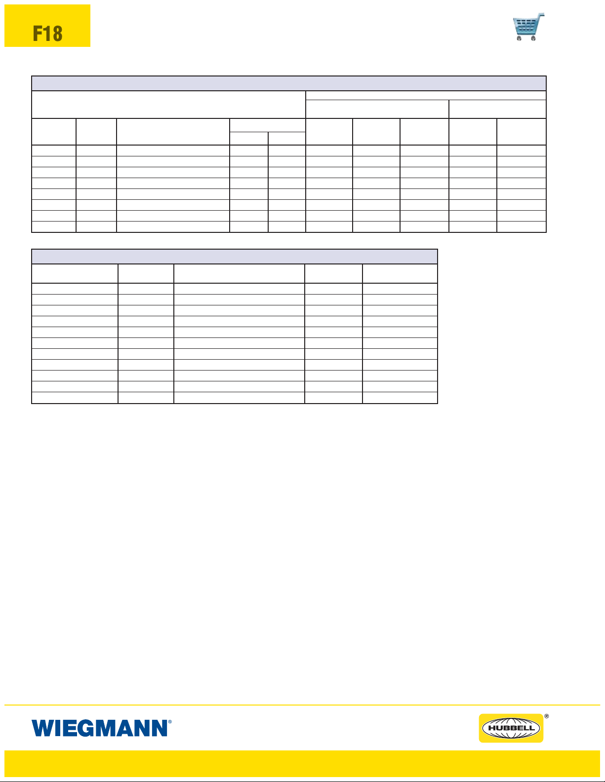
EATON CUTLER-HAMMER C371 CIRCUIT BREAKER OPERATORS FOR C-H CIRCUIT BREAKERS
ABN12, SDN12, SDN12PL, N412CD, SN4 & SSN4X WALL-MOUNTS
N412CSTD & N412CSSSTD (PAGES F2-F9) (PAGES F10-F13)
TYPE
NUMBER
C371E 225A F Frame: EHD, FDB, FD, HFD, FDC 6.00 5.50 4.44 6.81 11.44 8.44 11.44
C371E 150A F Frame: HMCP 6.00 5.50 4.44 6.81 11.44 8.44 11.44
C371F 250A J Frame: JDB, JD, HJD, JDC 8.94 8.00 — 6.75 11.25 — 11.25
C371F 250A J Frame: HMCP 10.94 8.00 — 6.75 11.25 — 11.25
C371F 400A K Frame: DK, KDB, KD, HKD 9.75 8.00 — — 10.75 — 10.75
C371F 400A K Frame: HMCP 9.75 8.00 — — 10.75 — 10.75
C371G 600A L Frame: LD, HLD, LDC 8.44 11.88 — — 9.18 — 9.18
C371G 600A L Frame: HMCP 8.44 11.88 — — 9.18 — 9.18
EATON CUTLER-HAMMER FLEX SHAFT™OPERATOR MECHANISMS FOR C-H CIRCUIT BREAKERS
COMPLETE OPERATOR AMP FRAME BREAKER BREAKER
MECHANISM RATING TYPE HEIGHT WIDTH
Catalog numbers for complete mechanisms include a flange-mounted handle, flexible shaft and circuit breaker mechanism.The last digit of the catalog number denotes the length of shaft (F1S03 = 3-foot shaft). The F, J, K frame Flex Shafts
are available in 3-foot to 10-foot lengths. The L, N, R frame Flex Shafts are available in 4-foot to 6-foot lengths.
Space Occupied by Disconnect
• The Flex Shaft
mechanism.
• Refer to National Electrical Code
• Choose the length of shaft based on placement of the circuit breaker in the enclosure ensuring a 4-inch min. bending
radius for the Flex Shaft
• Space occupied by circuit breaker is determined by overall height "X", width "Y", wire bend space "WB" and location "G"
as selected from right to left.
MAX
AMP
RATING WB WB WB WB WB
F1S03 225A F Frame: EHD, FDB, FD, HFD, FDC 6.00 4.12
F1S03 150A F Frame: HMCP 6.00 4.12
F2S03 250A J Frame: JDB, JD, HJD, JDC 10.00 4.12
F2S03 250A J Frame: HMCP 10.00 4.12
F3S03 400A K Frame: DK, KDB, KD, HKD 10.12 5.50
F3S03 400A K Frame: HMCP 12.45 5.50
F4S04 600A L Frame: LD, HLD, LDC 10.75 8.25
F4S04 600A L Frame: HMCP 12.50 8.25
F7S04 800A M Frame: MD, MDS 16.00 8.25
F5S04 1200A N Frame: ND, HND, NDC 16.00 8.25
F6S04 2500A R Frame: RD, CRD, RDC 16.00 15.50
™
system allows the circuit breaker to be positioned independent from the flange-mounted handle
™
.
FRAME TYPE
®
article 430-10(b) for wiring space "WB" required for line side conductors.
SPACE OCCUPIED
FG
WHEN WHEN WHEN WHEN WHEN
D=8.00 D=10.00 D=12 OR 16 D=8.00 D=12.00
WIRE BEND SPACE “WB” ABOVE DISCONNECT
™
www.hubbell-wiegmann.com
Data Subject To Change Without Notice
Page 19
ABN12, SDN12, SDN12PL, N412CD,
N412CSTD, N412CSSSTD, SN4 & SSN4X SERIES ENCLOSURES
DISCONNECT SPACE OCCUPIED & AVAILABLE WIRING SPACE INFORMATION
GENERAL ELECTRIC TYPE STDA OPERATORS FOR DISCONNECTS
ABN12, SDN12, SDN12PL, N412CD, SN4 & SSN4X WALL-MOUNTS
N412CSTD, N412CSSSTD & SN4 (PAGES F2-F9) (PAGES F10-F13)
MECHANISM
TDOM1A 30A No fuse — 7.75** 5.25 6.18* 7.62 12.12 9.12 12.12
TDOM1A 30A 30A-250V H, R 7.75** 5.25 6.18* 7.62 12.12 9.12 12.12
TDOM1B 30A 30A-600V H, R 12.38** 5.25 6.18* 7.62 12.12 9.12 12.12
TDOM1B 30A 60A-250V H, R 12.38** 5.25 6.18* 7.62 12.12 9.12 12.12
TDOM1B 30A 60A-600V H, R 12.38** 5.25 6.18* 7.62 12.12 9.12 12.12
TDOM1A 60A No fuse — 7.75** 5.25 6.18* 7.62 12.12 9.12 12.12
TDOM1B 60A 60A-250V H, R 12.38** 5.25 6.18* 7.62 12.12 9.12 12.12
TDOM1B 60A 60A-600V H, R 12.38** 5.25 6.18* 7.62 12.12 9.12 12.12
TDOM1B 60A 100A-250V H, R 12.38** 5.25 6.18* 7.62 12.12 9.12 12.12
TDOM1B 60A 100A-600V H, R 12.38** 5.25 6.18* 7.62 12.12 9.12 12.12
TDOM1A 100A No fuse — 7.75** 5.25 6.18* 7.62 12.12 9.12 12.12
TDOM1B 100A 100A-250V H, R 12.38** 5.25 6.18* 7.62 12.12 9.12 12.12
TDOM1B 100A 100A-600V H, R 12.38** 5.25 6.18* 7.62 12.12 9.12 12.12
TDOM1B 100A 200A-250V H, R 12.38** 5.25 6.18* 7.62 12.12 9.12 12.12
TDOM1B 100A 200A-600V H, R 12.38** 5.25 6.18* 7.62 12.12 9.12 12.12
TDOM2 200A No fuse — 7.00 9.12 — — 9.50 6.50 9.50
TDOM2 200A 200A-250V H, R 15.38 9.12 — — 9.50 6.50 9.50
TDOM2 200A 200A-600V H, R 15.38 9.12 — — 9.50 6.50 9.50
* Disconnect moved down .88" to fit on panel.
**Dimension applies to 8.00" (203mm) deep enclosures and is .88" less in deeper enclosures.
AMP FUSE FUSE
RATING CLIP CLASS
SPACE OCCUPIED
FG
WHEN WHEN WHEN WHEN WHEN
D=8.00 D=10.00 D=12 OR 16 D=8.00 D=12.00
WB WB WB WB WB
WIRE BEND SPACE “WB” ABOVE DISCONNECT
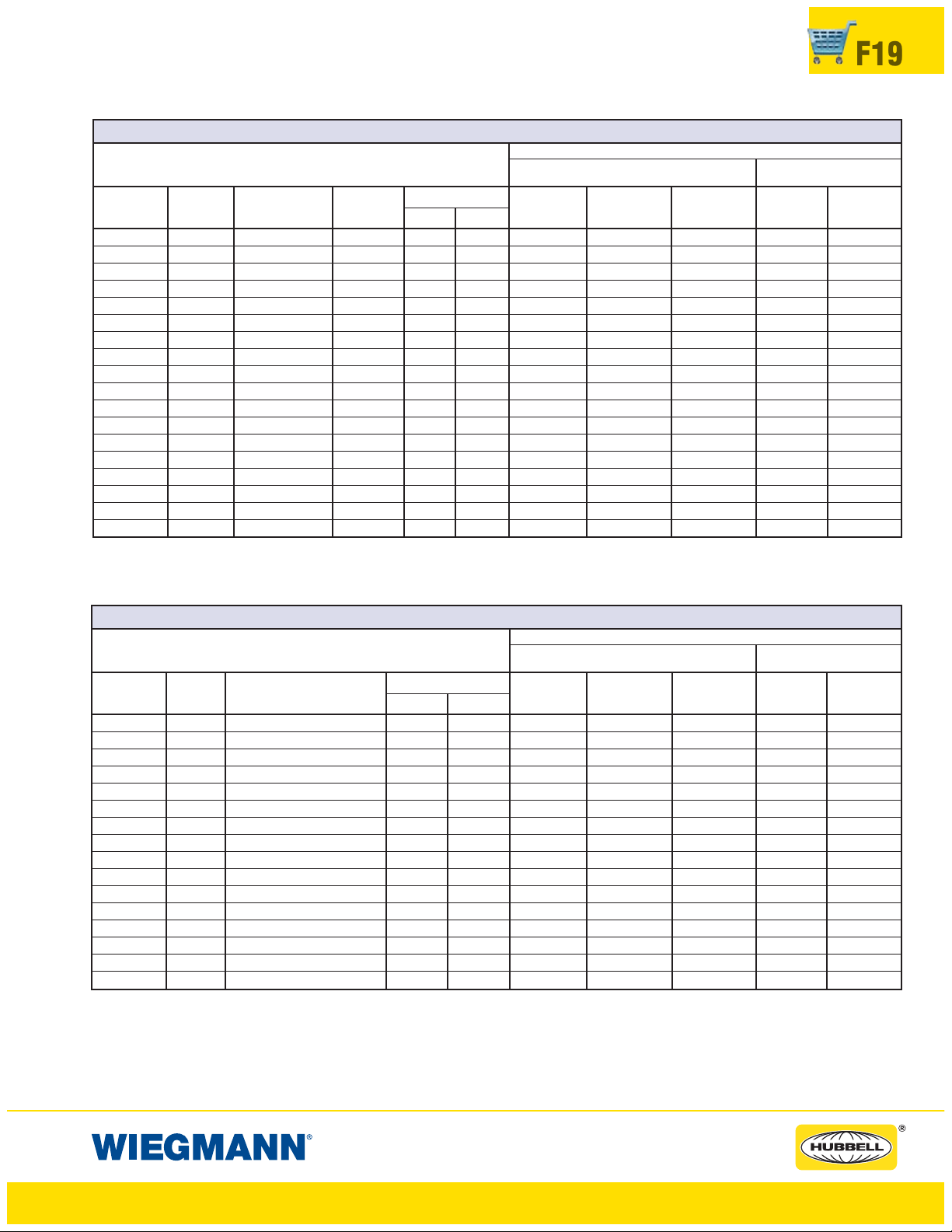
F19
GENERAL ELECTRIC TYPE STDA OPERATORS FOR CIRCUIT BREAKERS
OPERATORS FOR CIRCUIT BREAKERS
MECHANISM
SDOM1A 150A TEB, TED, THED 7.75** 5.25 6.06* 7.50 12.06 9.06 12.06
SDOM1A 150A TEC 7.75** 5.25 6.06* 7.50 12.06 9.06 12.06
TDOM1B 150A TB1 12.38** 5.25 6.06* 7.50 12.06 9.06 12.06
TDOM1B 150A TEC, TECL 12.38** 5.25 6.06* 7.50 12.06 9.06 12.06
TDOM1C 150A TEL 7.75** 5.25 6.06* 7.50 12.06 9.06 12.06
TDOM1D 150A THLC1 7.75** 5.25 — 5.12 9.62 6.62 9.62
TDOM3 225A TFJ 10.38 5.75 — 6.06 10.62 7.62 10.62
TDOM3 225A TFK, THFK, TFL 10.38 5.75 — 6.06 10.62 7.62 10.62
TDOM4 400A TJJ, TJK4, THJK4, TJL4V 8.25 9.38 — 5.12 9.69 6.69 9.69
TDOM4 600A TJK6, THJK6, TJ4V, TJL4V 8.25 9.38 — 5.12 9.69 6.69 9.69
TDOM5 400A TB4, TJH6S 14.25 9.38 — 5.12 9.69 6.69 9.69
TDOM6 225A TLB2, THLC2 11.75 9.38 — — 9.12 6.12 9.12
TDOM6 400A TLB4, THLC4 11.75 9.38 — — 7.75 4.75 7.75
SDOM1A 150A SPECTRA SE150 7.75** 5.25 6.06* 7.50 12.06 9.06 12.06
SDOM3 250A SPECTR SF250 10.38 5.75 — 6.06 10.62 7.06 10.06
SDOM4 600A SPECTRA SG600 10.00 7.00 — — 7.93 — 7.93
* Disconnect moved down .88" to fit on panel.
**Dimension applies to 8.00" (203mm) deep enclosures and is .88" less in deeper enclosures.
AMP
RATING
FRAME TYPE
SPACE OCCUPIED
FG
ABN12, SDN12, SDN12PL, N412CD, SN4 & SSN4X WALL-MOUNTS
N412CSTD, N412CSSSTD & SN4 (PAGES F2-F9) (PAGES F10-F13)
WHEN WHEN WHEN WHEN WHEN
D=8.00 D=10.00 D=12 OR 16 D=8.00 D=12.00
WB WB WB WB WB
WIRE BEND SPACE “WB” ABOVE DISCONNECT
www.hubbell-wiegmann.com
Data Subject To Change Without Notice
Page 20

F20
ABN12, SDN12, SDN12PL, N412CD,
N412CSTD, N412CSSSTD, SN4 & SSN4X SERIES ENCLOSURES
DISCONNECT SPACE OCCUPIED & AVAILABLE WIRING SPACE INFORMATION
GENERAL ELECTRIC CIRCUIT BREAKERS WITH SPECTRA FLEX™CABLE OPERATORS
FRAME MAXIMUM CIRCUIT BREAKER CIRCUIT BREAKER
SIZE AMP RATING HEIGHT X WIDTH Y
E150 150A 6.31 4.12
SE150 150A 6.31 4.12
SF250 250A 10.12 4.12
SG600 600A 10.09 5.50
SK1200 1200A 15.50 8.25
FRAME BREAKER FLANGE-MOUNTING OPERATING
SIZE MECHANISM HANDLE** CABLE*
E150 SCOM1A SCH1 SC3L
SE150/SF250 SCOM1EF SCH1 SC3L
SG600 SCOM1G SCH1 SC3L
SK1200 SCOM1K SCH2K SC3H
* Operating cables are available in 3-foot to 10-foot lengths. (The number 3 in the catalog number denotes
3-foot cable.)
** Add “X” for NEMA 4 or 4X flange-mounted handle.
ABN12, SDN12, SDN12PL, N412CD, SN4 & SSN4X
N412CSTD, N412CSSSTD, SN4 & SSN4X WALL-MOUNTS
For enclosures that
accept these devices,
see pages F2-F9.
For enclosures that
accept these devices,
see pages F10-F13.
Space Occupied by Circuit Breaker
• The General Electric Spectra-Flex
the flange-mounted handle mechanism.
• Refer to National Electrical Code
• Choose the operating cable length based on placement of the circuit breaker in the enclosure ensuring a 3"
minimum bending radius for the cable.
• Space occupied by circuit breaker is determined by overall circuit breaker size ("X" height and "Y" width)
plus "WB" wire bend space and location "G" as selected from right to left.
I-T-E DISCONNECT SWITCHES FOR MAX-FLEX™OPERATORS
SWITCH
MCS603R 30A No fuse — 5.52 6.13
MCS603R 30A 30A-250V H, K, R 8.11 6.13
MCS603R 30A 30A-600V H, K, R 10.11 6.13
MCS603R 30A 30A-600V J 8.48 6.13
MCS606R 60A No fuse — 5.52 6.13
MCS606R 60A 60A-250V H, K, R 7.86 6.13
MCS606R 60A 60A-600V H, K, R 10.38 6.13
MCS606R 60A 60A-600V J 8.36 6.13
MCS610R 100A No fuse — 7.59 7.38
MCS610R 100A 100A-250V H, K, R 11.85 7.38
MCS610R 100A 100A-600V H, K, R 13.85 7.38
MCS610R 100A 100A-600V J 10.60 7.38
MCS620R 200A No fuse — 9.02 9.17
MCS620R 200A 200A-250V H, K, R 14.70 9.17
MCS620R 200A 200A-600V H, K, R 17.20 9.17
MCS620R 200A 200A-600V J 13.32 9.17
AMP FUSE FUSE DISCONNECT DISCONNECT
RATING CLIP CLASS HEIGHT X WIDTH Y
™
system allows the circuit breaker to be positioned independent from
®
article 430-10(b) for wiring space "WB" required for line side conductors.
ABN12, SDN12, SDN12PL, N412CD, SN4 & SSN4X
N412CSTD, N412CSSSTD, SN4 & SSN4X WALL-MOUNTS
For enclosures that
accept these devices,
see pages F2-F9.
For enclosures
that accept these
devices, see
pages F10-F13.
www.hubbell-wiegmann.com
Data Subject To Change Without Notice
Page 21

ABN12, SDN12, SDN12PL, N412CD,
N412CSTD, N412CSSSTD, SN4 & SSN4X SERIES ENCLOSURES
DISCONNECT SPACE OCCUPIED & AVAILABLE WIRING SPACE INFORMATION
SIEMENS ITE CIRCUIT BREAKERS FOR MAX-FLEX™OPERATORS
COMPLETE OPERATOR CIRCUIT BREAKER MAXIMUM CIRCUIT BREAKER CIRCUIT BREAKER
MECHANISM FRAME AMP RATING HEIGHT X WIDTH Y
FHOE036 ED 125A 6.34 3.00 ED2. ED4. ED6. HED4. HED6
FHOE036 CED 125A 9.58 3.00 CED6
FHOF036 FD 250A 9.50 4.50 FXD6-A, FD6-A, HFD6, FXD6-ETJ, HHFD6, HHFXD6
FHOJ036 CFD 250A 14.25 4.50 CFD6, CFD6-ETI
FHOJ036 JD 400A 11.00 7.50 JXD2, JXD6, JD6, HJD6, HHJD6, HHJXD6, JXD6-ETI
FHOJ036 CJD 400A 17.86 7.50 CJD6, CJD6-ETI
FHOJ036 LD 600A 11.00 7.50 LXD6, LD6, HLD6, HHLD6, HHLDX6, LXD6-ETI
FHOJ036 CLD 600A 17.86 7.50 CLD6, CLD6-ETI
FHOLM036 LMD 800A 16.00 9.00 LMD6, LMXD6, HLMD6, HLMXD6, LMXD6-ETI
FHON048* MD 80 0 A 24. 00 9.0 0 MD2, MXD6, HMD6, HMXD6, CMD6, MXD6-ETI, CMD6-ETI
FHON048* ND 1200A 24.00 9.00 ND6, NXD6, HND6, HNXD6, CND6
Mechanisms and circuit breakers listed above will fit any disconnect wall-mounts
on pages F10-F13, or SN4 wall-mounts on pages F2-F9 except as noted.
The last 3 digits of operator mechanism number indicates cable length in inches.
Also 48" cables are available for ED, FD, JD/LD operators, and 60" cables for
MD/ND, PD/RD operators.
For Type 4 applications order handle, cable and circuit breaker separately.
*This operator mechanism can only be installed in catalog number
SDN12603812A (see page F3) which has the appropriate flange cutout.
Space Occupied by Disconnect
• The Siemens ITE Max-Flex
tioned independent from the flange-mounted handle mechanism.
• Refer to National Electrical Code
required for line side conductors.
• Refer to Siemens ITE Max-Flex
nect location when 36-inch or 48-inch Max-Flex
• Space occupied by disconnect is determined by overall height “X”, width
“Y”, wire bend space “WB” and location “G” as selected from right to left.
™
CIRCUIT BREAKER TYPE
cable system allows the disconnect to be posi-
®
article 430-10(b) for wiring space “WB”
™
installation instructions for limits on discon-
™
cables.
F21
SCHNEIDER SQUARE D®CLASS 9422 DISCONNECT SWITCHES USED WITH CABLE MECHANISM 9422-CFT30 & 9422A-1 HANDLE MECHANISM
SWITCH
TCN-30C 30A No fuse — 5.90 6.20
TCF-30C 30A 30A-250V H, K, R 7.50 6.20
TCF-33C 30A 30A-600V H, K, R 10.15 6.20
TCF-33C 30A 60A-250V H, K, R 8.15 6.20
TCF-33C 30A 30A-600V J 7.50 6.20
TDN-60C 60A No fuse — 5.90 6.20
TDF-60C 60A 30A-600V H, K, R 10.15 6.20
TDF-60C 60A 60A-250V H, K, R 8.15 6.20
TDF-63C 60A 60A-600V H, K, R 10.65 6.20
TDF-63C 60A 60A-600V J 7.50 6.20
TEN-10C 100A No fuse — 5.90 6.20
TEF-10C 100A 100A-250V H, K, R 10.35 6.20
TEF-10C 100A 100A-600V H, K, R 10.35 6.20
TEF-10C 100A 100A-600V J 10.35 6.20
Use switches listed above with appropriate cable mechanism and 9422-A1 handle mechanism.
SCHNEIDER SQUARE D®CLASS 9422 CABLE MECHANISM FOR CIRCUIT BREAKERS
CABLE TYPE AMP FRAME CIRCUIT BREAKER CIRCUIT BREAKER ABN12, SDN12, SDN12PL, N412CD, SN4 & SSN4X
SWITCH RATING TYPE HEIGHT X WIDTH Y N412CSTD, N412CSSSTD, SN4 & SSN4X WAL L-M OUNTS
9422 CGJ30 75A GJL 4.75 3.50
9422 CGJ300 100A GJL 4.75 3.50
9422 CGJ30 100A FAL, FHL 6.00 4.50
9422 CGJ30 250A KAL, KHL 8.00 4.50
9422 CGJ30 400A LAL, LHL, Q4L 11.00 6.00
Use cable mechanism with appropriate circuit breaker and 9422-A1 handle mechanism. Cable operators are available in 3-foot, 5-foot, and 10-foot lengths.
Numbers shown (30) are for 3-foot cables.
Space Occupied by Disconnect Switch or Circuit Breaker
• Schneider Square D®cable mechanisms allows disconnect devices to be
positioned independent from the flange-mounted handle mechanism.
•RefertoNational Electrical Code
required for line side conductors.
AMP FUSE FUSE DISCONNECT DISCONNECT ABN12, SDN12, SDN12PL, N412CD, S N 4 & SS N 4 X
RATING CLIP CLASS HEIGHT X WIDTH Y N412CSTD, N412CSSSTD, SN4 & SSN4X WALL-MOUNTS
®
article 430-10(b) for wiring space "WB"
For enclosures that
accept these devices,
see pages F2-F9.
For enclosures that
accept these devices,
see pages F2-F9.
• Choose cable mechanism length based on placement of disconnect in
enclosure. See Schneider Square D®Instruction Bulletin for minimum bend
radius for cable.
• Space occupied by disconnect is determined by overall height “X”, width
“Y”, wire bend space “WB” and location “G” as selected from right to left.
For enclosures that
accept these devices,
see pages F10-F13.
For enclosures that
accept these devices,
see pages F10-F13.
www.hubbell-wiegmann.com
Data Subject To Change Without Notice
Page 22

F22
ABN12, SDN12, SDN12PL, N412CD,
N412CSTD, N412CSSSTD, SN4 & SSN4X SERIES ENCLOSURES
DISCONNECT SPACE OCCUPIED & AVAILABLE WIRING SPACE INFORMATION
SCHNEIDER SQUARE D®CLASS 9422 VARIABLE DEPTH DISCONNECTS
ABN12, SDN12, SDN12PL, N412CD, SN4 & SSN4X WALL-MOUNTS
N412CSTD, N412CSSSTD & SN4 (PAGES F2-F9) (PAGES F10-F13)
MECHANISM
TCN-30 30A No fuse — 3.80 6.84 3.69 6.03 10.56 7.56 10.56
TCF-30 30A 30A-250V H, K, R 5.53 6.84 3.69 6.03 10.56 7.56 10.56
TCF-33 30A 30A-600V H, K, R 8.15 6.84 3.69 6.03 10.56 7.56 10.56
TCF-33 30A 60A-250V H, K, R 6.15 6.84 3.69 6.03 10.56 7.56 10.56
TCF-33 30A 30A-600V J 5.53 6.84 3.69 6.03 10.56 7.56 10.56
TDN-60 60A No fuse — 3.80 6.84 3.69 6.03 10.56 7.56 10.56
TDF-60 60A 30A-600V H, K, R 8.15 6.84 3.69 6.03 10.56 7.56 10.56
TDF-60 60A 60A-250V H, K, R 6.15 6.84 3.69 6.03 10.56 7.56 10.56
TDF-63 60A 60A-600V H, K, R 8.65 6.84 3.69 6.03 10.56 7.56 10.56
TDF-63 60A 60A-600V J 5.53 6.84 3.69 6.03 10.56 7.56 10.56
TEN-10 100A No fuse — 3.80 6.84 — 5.91 10.44 7.44 10.44
TEF-10 100A 100A-250V H, K, R 8.25 6.84 — 5.91 10.44 7.44 10.44
TEF-10 100A 100A-600V H, K, R 10.25 6.84 — 5.91 10.44 7.44 10.44
TEF-10 100A 100A-600V J 7.05 6.84 — 5.91 10.44 7.44 10.44
TC-1 30A No fuse — 5.75 6.00 3.12 5.12 9.62 6.62 9.62
TC-2 30A 30A-250V H, K, R 5.75 6.00 3.12 5.12 9.62 6.62 9.62
TC-3 30A 30A-600V H, K, R 7.75 6.00 3.12 5.12 9.62 6.62 9.62
TC-3 30A 60A-250V H, K, R 5.88 6.00 3.12 5.12 9.62 6.62 9.62
TC-3 30A 30A-600V J 5.75 6.00 3.12 5.12 9.62 6.62 9.62
TD-1 60A No fuse — 6.38 6.62 3.62 6.00 10.50 7.50 10.50
TD-2 60A 30A-600V H, K, R 8.50 6.62 3.62 6.00 10.50 7.50 10.50
TD-2 60A 60A-250V H, K, R 6.50 6.62 3.62 6.00 10.50 7.50 10.50
TD-3 60A 60A-600V H, K, R 9.00 6.62 3.62 6.00 10.50 7.50 10.50
TD-3 60A 60A-600V J 6.38 6.62 3.62 6.00 10.50 7.50 10.50
TE-1 100A No fuse — 4.75 8.38 — 5.75 10.25 — 10.25
TE-2 100A 100A-250V H, K, R 7.50 8.38 — 5.75 10.25 — 10.25
TE-2 100A 100A-600V H, K, R 9.50 8.38 — 5.75 10.25 — 10.25
TE-2 100A 100A-600V J 6.25 8.38 — 5.75 10.25 — 10.25
TE-3 100A 200A-600V J 13.75 8.38 — 5.75 10.25 — 10.25
TF-1 200A No fuse — 5.50 11.62 — — 8.88 — 8.88
TF-2 200A 200A-250V H, K, R 11.50 11.62 — — 8.88 — 8.88
TF-2 200A 200A-600V H, K, R 14.00 11.62 — — 8.88 — 8.88
TF-2 200A 200A-600V J 10.12 11.62 — — 8.88 — 8.88
TF-3 200A 400A-600V J 14.50 11.62 — — 8.88 — 8.88
SCHNEIDER SQUARE D®CLASS 9422 VARIABLE DEPTH
RG-1 75A GJL Circuit breaker 3.53 3.74 3.59 5.93 10.47 7.47 10.47
RG-1 100A GJL Circuit breaker 3. 53 3.74 3.59 5.93 10.47 7.47 10.47
RN-1 100A FAL, FHL Circuit breaker 5. 12 5.25 3.75 6.12 10.62 7.62 10.62
RP-1 250A KAL, KHL Circuit breaker 7 .12 5.62 4.25* 6.88 11.38 8.38 11.38
RR-1 400A LAL,LHL,Q4L Circuit breaker 7.62 8.75 — — 7.00 — 7.00
*Not recommended except with #1 or smaller line conductors.
AMP FUSE FUSE
RATING CLIP CLASS
SPACE OCCUPIED
FG
WHEN WHEN WHEN WHEN WHEN
D=8.00 D=10.00 D=12 OR 16 D=8.00 D=12.00
WB WB WB WB WB
WIRE BEND SPACE “WB” ABOVE DISCONNECT
www.hubbell-wiegmann.com
Data Subject To Change Without Notice
Page 23

ABN12 FIXED DEPTH SERIES ENCLOSURES
NEMA 12 FLANGED SINGLE DOOR DISCONNECT
Industry Standards
UL 508
,Types12&13
CSA Certified, Type 12
NEMA/EEMAC Types 12 & 13
UL File E64791
F23
ABN12242108
FEATURES-SPECIFICATIONS
Applications
Designed to house Allen-Bradley 1494F
flange-mounted disconnect switches
and Bulletin 1494D
operators for circuit breakers. Provides
protection from dust, dirt, oil and water.
Construction
• Bodies and doors fabricated from
14 gauge steel
• Plasma welded seams
• Rolled lip around all sides of
enclosure opening excludes liquids
and contaminants
• Doors easily removed by pulling
continuous hinge pin
• Polyurethane poured-in-place gasket
• External mounting feet
• Collar studs for mounting optional
back panel
• Grounding provisions provided
• Holes are provided in body and door
for mounting disconnect switch, operating mechanism and door hardware.
flange-mounted
• Guide brackets and door catch are
welded to inside of door
• Locking bars are also provided for
door hardware
• Spacers and screws are provided
to secure disconnect switch and
fuse block adapter plate to the panel
• Print pocket is provided
• Enclosures under 40" high require
2-point door hardware
• Enclosures 40" high and larger
require 3-point door hardware
• Instructions to locate and install
disconnect switches, circuit breakers,
and operating mechanisms is
provided
Finish
• ANSI 61 gray polyester powder inside
and out over phosphatized surfaces
• Optional back panels are white
polyester powder over phosphatized surfaces
• Optional “G”panelshaveaconductive finish
CSA File LL66078
Accessories
• Back panels (reference tables)
• Blank Adapter Plates are on page
F61
IMPORTANT
• Disconnect switch or circuit breakers, operating handle, operating
mechanism, and door hardware
are not furnished with enclosure
and must be ordered separately
from the disconnect manufacturer
• Operator adapter plates are not
required with this enclosure
• Disconnect and door hardware
ordering information is located on
page F25
• Review space occupied by disconnect drawing on page F25 and
disconnect tables on page F26 to
determine if the disconnect device
you are using will fit the enclosure
size you have selected
ABN12 FIXED DEPTH SERIES WALL-MOUNT DISCONNECTS
CATALOG BODY/DOOR ENCLOSURE SIZE BACK PANEL CATALOG NUMBER* BACK PANEL
NUMBER STEELGAUGE HXWXD WHITE “G” SIZE A X B
ABN12242108 14/14 24.00x21.38x8.13 (610x543x206) NP2420 NP2420 21.00x17.00 (533x432)
ABN12242508 14/14 24.00x25.38x8.13 (610x645x206) NP2424 NP2424 21.00x21.00 (533x533)
ABN12302108 14/14 30.00x21.38x8.13 (762x543x206) NP3020 NP3020 27.00x17.00 (686x432)
ABN12302508 14/14 30.00x25.38x8.13 (762x645x206) NP3024 NP3024 27.00x21.00 (686x533)
ABN12362508 14/14 36.00x25.38x8.13 (914x645x206) NP3624 NP3624 33.00x21.00 (838x533)
ABN12363108 14/14 36.00x31.38x8.13 (914x797x206) NP3630 NP3630 33.00x27.00 (838x686)
ABN12423108 14/14 42.00x31.38x8.13 (1067x797x206) NP4230 NP4230 39.00x27.00 (991x686)
ABN12242110 14/14 24.00x21.38x10.13 (610x543x257) NP2420 NP2420 21.00x17.00 (533x432)
ABN12242510 14/14 24.00x25.38x10.13 (610x645x257) NP2424 NP2424 33.00x21.00 (838x533)
ABN12302110 14/14 30.00x21.38x10.13 (762x543x257) NP3020 NP3020 27.00x17.00 (686x432)
ABN12302510 14/14 30.00x25.38x10.13 (762x645x257) NP3024 NP3024 27.00x21.00 (686x533)
*Back panels must be ordered separately.
www.hubbell-wiegmann.com
Data Subject To Change Without Notice
Page 24

F24
ABN12 FIXED DEPTH SERIES ENCLOSURES
NEMA 12 FLANGED SINGLE DOOR DISCONNECT
ABN12 FIXED DEPTH SERIES WALL-MOUNT DISCONNECTS (CONT.)
CATALOG BODY/DOOR ENCLOSURE SIZE BACK PANEL CATALOG NUMBER* BACK PANEL
NUMBER STEEL GAUGE HXWXD WHITE “G” SIZEAXB
ABN12362510 14/14 36.00x25.38x10.13 (914x645x257) NP3624 NP3624G 33.00x21.00 (838x533)
ABN12363110 14/14 36.00x31.38x10.13 (914x797x257) NP3630 NP3630G 33.00x27.00 (838x686)
ABN12423110 14/14 42.00x31.38x10.13 (1067x797x257) NP4230 NP4230G 39.00x27.00 (991x686)
ABN12483710** 14/14 48.00x37.38x10.13 (1219x949x257) NP4836 NP4836G 45.00x33.00 (1143x838)
ABN12603710** 14/14 60.00x37.38x10.13 (1524x949x257) NP6036 NP6036G 57.00x33.00 (1448x838)
ABN12363212 14/14 36.00x32.38x12.13 (914x822x308) NP3630 NP3630G 33.00x30.00 (838x762)
ABN12423212 14/14 42.00x32.38x12.13 (1067x822x308) NP4230 NP4230G 45.00x30.00 (1143x762)
ABN12483812** 14/14 48.00x38.38x12.13 (1219x975x308) NP4836 NP4836G 45.00x34.00 (1143x864)
ABN12483812A*** 14/14 48.00x38.38x12.13 (1219x975x308) NP4836 NP4836G 45.00x34.00 (1143x864)
ABN12603812 14/14 60.00x38.38x12.13 (1524x975x308) NP6036 NP6036G 57.00x34.00 (1448x864)
ABN12603812A*** 14/14 60.00x38.38x12.13 (1524x975x308) NP6036 NP6036G 57.00x34.00 (1448x864)
ABN12483816 14/14 48.00x38.38x16.13 (1219x975x410) NP4836 NP4836G 45.00x33.00 (1143x838)
ABN12603816 14/14 60.00x38.38x16.13 (1524x975x410) NP6036 NP6036G 57.00x33.00 (1448x838)
*Back panels must be ordered separately.
**Enclosures are supplied with closed cell neoprene gasket (not foam-in-place)
***Suitable for 200 AMP disconnect Switches and 1494FL4 door hardware only. Blank adapter plate WA22BAP will not fit on these enclosures.
0.63
3.00
Ø0.44
W
3.00
2.00
D
Y
OMIT TWO MIDDLE STUDS
IF W = LESS THAN 32.00"
1.50
3.00
X
W-3.00
H
1.25
0.63
0.63
0.88
1.31
D
0.19
Note:
E = 3.84 when Depth = 8.00
E = 6.75 when Depth = 10.00
E = 9.50 when Depth = 12.00
(Except enclosures for 200 amp switches)
E = 9.50 when Depth = 16.00
E = 10.50 when Depth = 12.00
(Except enclosures for 200 amp switches)
WB = Wiring Space
0.44
CONTINUOUS
HINGE
1.09
GASKET
3/8 - 16 COLLAR
STUD
12 GA.
MOUNTING
FEET
H-1.56
DOOR STIFFENER
IF H = 42.00" OR MORE
1.25 TYP
SECTION X-X
1.25
D-0.28
X
3.00
Y
Notes:
DOOR
STIFFENER
2.38
2.75
PANEL
(ORDER SEPARATELY)
BODY
STIFFENER
Disconnects will occupy space on panel shown by
Dimensions “E”, “ F”, & “G”. Wiring space “WB” is
available when disconnect is installed in the enclosure.
Refer to National Electrical Code article 430-10(b)
for wiring space requited for line side conductors to be
connected to disconnect. Verify you application to
determine if wiring space is adequate.
14 GA.
0.75
1. Large print pocket (8" x 10") is
provided in each enclosure.
2. Panels are made from 12 Ga. steel.
3. Panels have flanges along all sides
when either dimension exceeds 17".
4. Enclosures under 40" high require
2-point door hardware and enclosures
40" high and larger require 3-point
door hardware.
5. See page F27 for Stiffener Locations.
0.88
0.88
1.50
THIS SPACE IS OCCUPIED
BY DISCONNECT SWITCH
AND FUSE CLIP (IF USED)
OR CIRCUIT BREAKER.
H-6.00
B1.75 2.62
1.50
MOUNTING FEET
SECTION Y-Y
WB
C
L
G
PANEL
(Order
Separately)
STIFFENER
SEE Page F27
OMIT TWO MIDDLE
STUDS IF H = LESS
THAN 31.00"
A
TOP HOLE IN
R.H. FLANGE.
E
F
1.31
2.63
www.hubbell-wiegmann.com
Data Subject To Change Without Notice
Page 25

ABN12 FIXED DEPTH SERIES ENCLOSURES
o
17"
NEMA 12 FLANGED SINGLE DOOR DISCONNECT
F25
Space Occupied by Disconnect
E =3.84 when Depth = 8.00
E =6.75 when Depth = 10.00
E = 9.50 when Depth = 12.00
(Except enclosures for 200 amp switches)
E = 9.50 when Depth = 16.00
E = 10.50 when Depth = 12.00
(Except enclosures for 200 amp switches)
WB = Wiring Space
See page F26 for various brands of disconnects for “F”, “G” & “WB” dimensions.
Disconnects will occupy space on panel
shown by dimensions “E”, “F” & “G”. Wiring
space “WB” is available when disconnect is
installed in the enclosure.
Refer to National Electrical Code
®
article
430-10(b) for wiring space required for line
side conductors to be connected to disconnect. Verify your application to determine if
wiring space is adequate.
ension exceeds
er 40" high require
dware and enclosures
ger require 3-point
r Stiffener Locations.
THIS SPACE IS OCCUPIED
BY DISCONNECT SWITCH
AND FUSE CLIP (IF USED)
OR CIRCUIT BREAKER.
.
1.50
TOP HOLE IN
R.H. FLANGE.
WB
C
L
G
E
F
1.31
2.63
DISCONNECT ORDERING INFORMATION
When ordering wall-mounted disconnects from the following manufacturer, be sure to order
all of the necessary items. Order the following items from the disconnect manufacturer.
Allen-Bradley
When using a Bulletin 1494F disconnect
switch, order:
*1. A disconnect switch (30A, 60A,
or 100A)
2. A fuse block adapter, if required
2. Line and load connectors, if required
**4. Door hardware (Bulletin 1494F-L1 for
2-point latching, or Bulletin 1494F-L2
and 1494F-L3 for 3-point latching)
When using a Bulletin 1494D circuit
breaker operating mechanism, order:
1. A circuit breaker (C-H)
2. An operating mechanism
3. A slide mechanism
**4. Door hardware Bulletin 1494F-L1 for
2-point latching, or Bulletin 1494F-L2
and 1494F-L3 for 3-point latching)
* Items available from disconnect manufacturer as complete kits.
**Enclosure “H” dimension less than 40" (1016mm) requires a 2-point door hardware (one Allen-Bradley
catalog number 1494F-L1). Enclosures with an “H” dimension of 40.00-inches or more require a 3point door hardware (one Allen-Bradley catalog number 1494F-L2 and one catalog number 1494F-L3.
PLEASE NOTE:
1. Operator adapter plates are not required
with enclosures on page F61.
2. Various other switch accessories and
circuit breaker accessories are available
from disconnect manufacturers. The
above information is subject to change
without notice. Please contact
Hubbell/Wiegmann or the disconnect
manufacturer if there are further questions.
3. The “Space Occupied” tables (page
F26) are based upon information supplied by the disconnect manufacturer.
Hubbell/Wiegmann does not assume
responsibility for the accuracy of these
dimensions.
www.hubbell-wiegmann.com
Data Subject To Change Without Notice
Page 26

F26
ABN12 /1494F & 1494D SERIES ENCLOSURES
DISCONNECT SPACE OCCUPIED & AVAILABLE WIRING SPACE INFORMATION
ALLEN-BRADLEY 1494F DISCONNECT SWITCHES
WIRE BEND SPACE “WB” ABOVE DISCONNECT
ABN12 / 1494F (PAGES F20-22)
FITS ENCLOSURE DEPTH
8.00 10.00 12.00 16.00
(203) (254) (305) (406) WB WB WB
••••N30 30A No fuse — 4.62 6.25 3.25 6.25 8.88
••••NF30 30A 30A-250V H, K, R 6.25 6.25 3.25 6.25 8.88
••••NF30 30A 60A-250V H, K, R 7.25 6.25 3.25 6.25 8.88
••••NF30 30A 30A-600V H, K, R 9.25 6.25 3.25 6.25 8.88
••••NF30 30A 60A-600V H, K, R 9.75 6.25 3.25 6.25 8.88
••••NF30 30A 30A-600V J 6.50 6.25 3.25 6.25 8.88
••••NF30 30A 60A-600V J 6.62 6.25 3.25 6.25 8.88
••••N60 60A No fuse — 4.62 6.25 2.50 5.25 8.12
••••NF60 60A 30A-600V H, K, R 10.38 6.25 2.50 5.25 8.12
••••NF60 60A 60A-250V H, K, R 8.38 6.25 2.50 5.25 8.12
••••NF60 60A 100A-250V H, K, R 10.88 6.25 2.50 5.25 8.12
••••NF60 60A 60A-600V H, K, R 10.88 6.25 2.50 5.25 8.12
••••NF60 60A 100A-600V H, K, R 12.88 6.38 2.50 5.25 8.12
••••NF60 60A 60A-600V J 7.75 6.25 2.50 5.25 8.12
••••NF60 60A 100A-600V J 9.75 6.25 2.50 5.25 8.12
—•••N100 100A No fuse — 4.62 7.00 — 3.50 6.25
—•••NF100 100A 100A-250V H, K, R 11.38 7.00 — 3.50 6.25
—•••NF100 100A 200A-250V H, K, R 12.25 7.25 — 3.50 6.25
—•••NF100 100A 100A-600V H, K, R 13.38 7.12 — 3.50 6.25
—•••NF100 100A 200A-600V H, K, R 14.75 7.38 — 3.50 6.25
—•••NF100 100A 100A-600V J 10.12 7.00 — 3.50 6.25
—•••NF100 100A 200A-600V J 10.88 7.25 — 3.50 6.25
——•—N200 200A* No fuse — 7.12 10.00 — — 7.00
——•—NF200 200A* 200A-250V H, K, R 15.00 10.00 — — 7.00
——•—NF200 200A* 400A-250V H, K, R 16.56 10.38 — — 7.00
——•—NF200 200A* 200A-600V H, K, R 17.56 10.00 — — 7.00
——•—NF200 200A* 400A-600V H, K, R 19.56 10.62 — — 7.00
——•—NF200 200A* 200A-600V J 13.69 10.00 — — 7.00
——•—NF200 200A* 400A-600V J 15.00 10.25 — — 7.00
TYPE AMP FUSE FUSE
NUMBER RATING CLIP CLASS
SPACE OCCUPIED
FG**
WHEN WHEN WHEN
E=3.84 E=6.75 E=9.50
ALLEN-BRADLEY 1494D CIRCUIT BREAKER OPERATORS
WIRE BEND SPACE “WB” ABOVE DISCONNECT
ABN12 / 1494D (PAGES F20-22)
FITS ENCLOSURE DEPTH
8.00 10.00 12.00 16.00
(203) (254) (305) (406) WB WB WB
•• • •
•••
•••
•••
* 200 amp switches can be installed only in 12.00-inch (305mm) deep enclosures that have provisions for 200 amp switches.
** The “G” dimension does not include space for auxiliary switches. See Allen-Bradley instructions for additional space required.
TYPE FRAME BREAKER TYPE
NUMBER RATING FRAME SIZE (3POLE)
N4/N40 150A 5.81 4.31 3.25 6.12 8.88
N5/N55 225A
N5/N50 250A
N5/N60 400A
EHD, FD, FDB, FDC, HFD, HMCP
General Electric
TFK, THFK, TFC
C-H
JD, JDB, JDC, HJD, HMCP
C-H
KD, KDB, KDC, HKD, HMCP
SPACE OCCUPIED
FG
8.81 4.50 — 5.34 8.09
8.81 4.50 — 5.31 8.06
8.81 5.62 — 5.44 8.19
WHEN WHEN WHEN
E=3.84 E=6.75 E=9.50
www.hubbell-wiegmann.com
Data Subject To Change Without Notice
Page 27

SDN12, SDN12 - PL, N412 - CD, N412 - CDSS, ABN12, SN4 & SSN4X SERIES
DISCONNECT ENCLOSURES STIFFENER MATRIX
F27
SDN12 & SDN12-PL SERIES WALL-MOUNT DISCONNECTS
CATALOG NUMBER STIFFENER
WITH HANDLE WITHOUT HANDLE
SDN12202108PL SDN12202108 NO NO
SDN12242108PL SDN12242108 NO NO
SDN12242508PL SDN12242508 NO NO
SDN12302108PL SDN12302108 NO NO
SDN12302508PL SDN12302508 NO NO
SDN12362508PL SDN12362508 NO NO
SDN12363108PL SDN12363108 NO YES
SDN12423208PL SDN12423208 YES YES
SDN12423708PL SDN12423708 YES YES
SDN12483708PL SDN12483708 YES YES
SDN12603808PL SDN12603808 YES YES
SDN12202110PL SDN12202110 NO NO
SDN12242110PL SDN12242110 NO NO
SDN12242510PL SDN12242510 NO NO
SDN12302110PL SDN12302110 NO NO
SDN12302510PL SDN12302510 NO NO
SDN12362510PL SDN12362510 NO NO
SDN12363110PL SDN12363110 NO YES
SDN12423110PL SDN12423110 YES YES
SDN12423710PL SDN12423710 YES YES
SDN12483710PL SDN12483710 YES YES
SDN12603710PL SDN12603710 YES YES
SDN12302612PL SDN12302612 NO NO
SDN12363212PL SDN12363212 NO YES
SDN12423212PL SDN12423212 YES YES
SDN12423812PL SDN12423812 YES YES
SDN12483812PL SDN12483812 YES YES
SDN12603812PL — YES YES
SDN12603812APL SDN12603812A YES YES
SDN12363116PL SDN12363116 NO YES
SDN12483816PL SDN12483816 YES YES
SDN12603816PL SDN12603816 YES YES
ABN12 SERIES WALL-MOUNT DISCONNECTS
CATALOG NUMBER
ABN12242108 NO NO
ABN12242508 NO NO
ABN12302108 NO NO
ABN12302508 NO NO
ABN12363108 NO YES
ABN12423108 YES YES
ABN12362510 NO NO
ABN12363110 NO YES
ABN12483710 YES YES
ABN12603710 YES YES
ABN12483812 YES YES
ABN12483816 YES YES
DOOR
STIFFENER
DOOR BODY
BODY
N412-CD ULTIMATE SERIES WALL-MOUNT DISCONNECTS
CATALOG NUMBER
N412202208CD NO NO
N412242208CD NO NO
N412242608CD NO NO
N412302608CD NO NO
N412362608CD NO YES
N412363208CD YES YES
N412423212CD YES YES
N412423812CD YES YES
N412603812CD YES YES
N412-CDSS ULTIMATE SERIES STAINLESS WALL-MOUNT DISCONNECTS
N412242208CDSS NO NO
N412242608CDSS NO NO
N412302608CDSS NO NO
N412362608CDSS NO NO
N412363208CDSS NO NO
N412423212CDSS NO YES
N412423812CDSS YES YES
N412483812CDSS YES YES
N412423812CDSS YES YES
SN4 SERIES WALL-MOUNT DISCONNECTS
CATALOG NUMBER
SN4242108 NO NO
SN4242508 NO NO
SN4302508 NO NO
SN4363108 NO YES
SN4423112 YES YES
SN4423712 YES YES
SN4483712 YES YES
SN4603712 YES YES
SSN4X SERIES WALL-MOUNT DISCONNECTS
CATALOG NUMBER
SSN4X242108 NO NO
SSN4X242508 NO NO
SSN4X302508 NO NO
SSN4X362508 NO NO
SSN4X363108 NO YES
SSN4X423112 YES YES
SSN4X423712 YES YES
SSN4X483712 YES YES
SSN4X603712 YES YES
STIFFENER
DOOR BODY
STIFFENER
DOOR BODY
STIFFENER
DOOR BODY
www.hubbell-wiegmann.com
Data Subject To Change Without Notice
Page 28
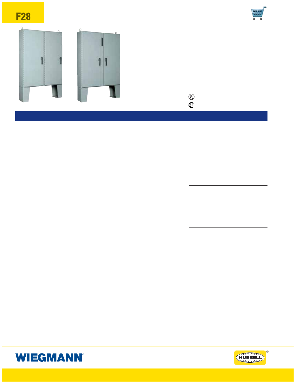
F28
WAX-U & WACPX-U SERIES ENCLOSURES
NEMA 12 FLOOR-MOUNT DISCONNECT
WA60X4912U
WA60CPX4912U
FEATURES-SPECIFICATIONS
Industry Standards
UL 508, Type 12
CSA Certified, Type 12
NEMA/EEMAC Type 12
UL File E64791
CSA File LL66078
Applications
The Wiegmann universal cutout is used in
large freestand and floorstand enclosures.
Operator Adapter Kits are required in order
to install the various manufacturers’ hardware. Note that 400 A (or greater) disconnect switches and 600 A (or greater) circuit
breakers need to use the “Large” or “High
Amp” cutout, which is provided in the
WA21ABVA kit for Allen-Bradley variabledepth disconnect switches or the WA21ITE
kit for Siemens (and select other manufacturers) flex-cable devices. The “Large” or
“High Amp” cutout accepts the larger operating handle whose mounting hole centers
are 6.500-in. apart.
Allen-Bradley
• 1494V disconnect switches with flangemount variable depth operating mechanisms and 1494V flange-mounted variable depth operating mechanisms for circuit breakers
• 140U flexible cable operating mechanisms and 140U molded case circuit
breakers
• 1494C cable-operated disconnect
switches with flange-mount handles
• 194RC cable-operated flange-mount
handles for use with the NFPA 79 compliant 194R IEC rotary disconnect switches
Allen-Bradley 1494V-R1, -R2 and -W2 operating handles and Allen-Bradley 1494F disconnect devices or 1494D circuit breaker
operators will NOT fit these enclosures.
• ABB Controls flange-mounted variable
depth operating mechanisms for disconnect switches and circuit breakers
• Eaton Cutler-Hammer Type C361 discon-
nect switches and operating mechanisms, and Type C371 circuit breakers
and circuit breakers operating mechanisms. Also Type SM safety handle
mechanisms and Flex Shaft
™
handle
operators for circuit breakers
• General Electric Type STDA flange han-
dles and variable depth operating mechanisms for disconnect switches and circuit breakers. Also Spectra Flex
™
cable
operators for circuit breakers
™
• Siemens ITE Max-Flex
flange-mounted
variable depth operating handles for disconnect switches and circuit breakers
®
• Schneider Square D
disconnect switches and circuit breakers used with Class
9422 flange-mounted variable depth
operating mechanisms or cable mechanisms
These enclosures will not receive Class
9422 bracket-mounted disconnect
devices, 9422TG1, or TG2 devices
Construction
• Bodies and doors fabricated from
10 gauge steel
• Continuously welded seams ground
smooth
• Body stiffeners provided for extra rigidity
• Heavy gauge continuous hinges to
secure doors
• Heavy duty 3-point padlocking handles
on all doors
• Print pocket is provided
• 15-inch floor stands are welded to enclosure
• Doors are sealed with polyurethane
poured-in-place gasket
• Heavy duty lifting eyes and provisions for
fluorescent lighting are provided
• Panel supports
• Collar studs are provided for mounting
optional sub panels
• Grounding provisions provided
• Unless specified, the right door is considered to be the “master” door on the
“Right Flange” mount enclosures and the
left door is the “master” door on the
“Center Post” mount enclosures
• A mechanical interlock is provided and
prevents the slave door from opening
before opening the master door
• Disconnects come with a universal cutout
which provides mounting for most disconnects operators by using operator
adapters
• Removable center post permits easy
panel installation
• FTC rolled lip around all sides of enclosure opening excludes liquids and contaminants
Finish
• ANSI 61 gray polyester powder inside
and out over phosphatized surfaces
• Optional back panels are white poly-
ester powder over phosphatized surfaces
• Optional “G” panels have a conductive
finish
Accessories
• Back panels (reference tables)
• See pages J1-J22
• Blank adapter plates on pages F61
IMPORTANT
• Disconnect switch or circuit breakers,
operating handle and operating mechanism are not furnished with the enclosure
and must be ordered separately from the
disconnect manufacturer.
• Operator adapter plates are required with
this enclosure and must be purchased
separately. See page F61 to select the
proper operator adapter for the brand
and type of disconnect being used
• Disconnect ordering information is located on page F31
• Review space occupied by disconnect
drawings on page F30 and disconnect
tables on pages F51-F60 to determine if
the disconnect device you are using will
fit the enclosure size you have selected
www.hubbell-wiegmann.com
Data Subject To Change Without Notice
Page 29

WAX-U & WACPX-U SERIES ENCLOSURES
NEMA 12 FLOOR-MOUNT DISCONNECT
WAX-U AND WACPX-U SERIES FLOOR-MOUNT DISCONNECTS
PROVISION CATALOG NUMBER
RIGHT FLANGE MNT. CENTER POST MNT.
WA60X4912U WA60CPX4912U 10/10 60.13x49.75x12.13 (1527x1264x308) NPDD6048 NPDD6048G 56.00x44.00 (1422x1118)
WA60X4918U — 10/10 60.13x49.75x18.13 (1527x1264x460) NPDD6048 NPDD6048G 56.00x44.00 (1422x1118)
WA60X4924U WA60CPX4924U 10/10 60.13x49.75x24.13 (1527x1264x613) NPDD6048 NPDD6048G 56.00x44.00 (1422x1118)
WA60X6112U WA60CPX6112U 10/10 60.13x61.75x12.13 (1527x1568x308) NPDD6060 NPDD6060G 56.00x56.00 (1422x1422)
WA60X6118U — 10/10 60.13x61.75x18.13 (1527x1568x460) NPDD6060 NPDD6060G 56.00x56.00 (1422x1422)
WA60X6124U WA60CPX6124U 10/10 60.13x61.75x24.13 (1527x1568x613) NPDD6060 NPDD6060G 56.00x56.00 (1422x1422)
WA72X6112U — 10/10 72.13x61.75x12.13 (1832x1568x308) NPDD7260 NPDD7260G 68.00x56.00 (1727x1422)
WA72X6118U — 10/10 72.13x61.75x18.13 (1832x1568x460) NPDD7260 NPDD7260G 68.00x56.00 (1727x1422)
WA72X7312U WA72CPX7312U 10/10 72.13x73.75x12.13 (1832x1873x308) NPDD7272 NPDD7272G 68.00x68.00 (1727x1727)
WA72X7318U WA72CPX7318U 10/10 72.13x73.75x18.13 (1832x1873x460) NPDD7272 NPDD7272G 68.00x68.00 (1727x1727)
WA72X7324U — 10/10 72.13x73.75x24.13 (1832x1873x613) NPDD7272 NPDD7272G 68.00x68.00 (1727x1727)
*Back panels must be ordered separately. Panels are made from 10 gauge steel.
BODY/DOOR ENCLOSURE SIZE BACKPANEL CATALOG NUMBER* BACKPANEL
STEELGAUGE HXWXD
WHITE “G”
SIZE A X B
F29
WAX-U
0.69
H H - 1.38
0.69
15.00
WACPX-U
0.69
1.75 W/2 - 3.50
H H - 1.38
0.69
15.00
3.50
W
1.94
1.50
H - 3.00
1.50
CONTINUOUS
HINGE
X
X
W/2 - 4.13
0.81 2.191.75
1.94 4.81 4.81
1.94
1.75 W/2 - 4.13
1.94
W/2 - 2.38 W/2 - 2.38
REMOVABLE
CENTER POST
FRONT VIEW
REMOVABLE
W
1.88 0.81
X
1.50
X
3.50
W/2 - 3.50
H - 3.00
3.00
TYP
1.50
0.81
1.94 4.81 4.81 1.94
1.94
1.94
W/2 - 1.75 W/2 - 1.75
CENTER POST
LIFTING
EYE
CLEAR
SPACE
AVAILABLE
3.00
3.00
TYP
BODY STIFFENER
(NOT PROVIDED IF
H OR W = 56.00"
1.75
CLEAR
SPACE
AVAILABLE
BODY STIFFENER
(NOT PROVIDED IF
H OR W = 56.00"
CONTINUOUS
HINGE
OPTIONAL
PANEL
OR LESS)
PANEL
SUPPORT
OPTIONAL
PANEL
OR LESS)
PANEL
SUPPORT
0.88
3.31
0.88
3.31
0.88
0.88
LIGHT BRACKET
(UNISTRUT CHANNEL)
2.06
A
2.06
SECTION Y-Y
LIGHT BRACKET
(UNISTRUT CHANNEL)
2.06
A
2.06
D1.25
Y
PADLOCKING
HANDLE
B
2.44
C
L
D
0.438
1.0 0
SECTION X-X
H/2 + 15.00"
C
L
Y
SIDE VIEW
D1.25
Y
PADLOCKING
HANDLE
B
2.44
C
L
H/2 + 15.00"
D
0.438
1.00
SECTION X-X
C
L
FRONT VIEW
SECTION Y-Y
www.hubbell-wiegmann.com
Data Subject To Change Without Notice
SIDE VIEW
Y
Page 30

F30
WAX-U & WACPX-U SERIES ENCLOSURES
NEMA 12 FLOOR-MOUNT DISCONNECT
Space Occupied by Disconnect
WB
C
L
PANEL
TOP OF DISCONNECT
TOP HOLE IN
DISCONNECT HANDLE
THIS SPACE
OCCUPIED BY
DISCONNECT
SWITCH AND
FUSE CLIP
(IF USED) OR
CIRCUIT BREAKER
G 2.44
"WAX-U" Style Enclosure
2.062.06
E
F
WB
C
L
DISCONNECT HANDLE
PANEL
TOP OF DISCONNECT
TOP HOLE IN
THIS SPACE
OCCUPIED BY
DISCONNECT
SWITCH AND
FUSE CLIP
(IF USED) OR
CIRCUIT BREAKER
AND OPERATING
HANDLE
G + 1.18
"WACPX-U" Style Enclosure
Note:
1. See pages F51-F60 for various brands of disconnects for “E”,“F”,“G”,“K”
and “WB” dimensions.
2. Disconnects will occupy space on panel shown by dimensions “E”,“F”,
“G” and “K”. Wiring space “WB” is available when disconnect is installed
in the enclosure.
3. When ordering 24.13 (613mm) deep enclosures, long connecting
rods must be ordered. Long connecting rods are available from disconnect manufacturers.
• ABB Controls flange-operated devices
• Eaton Cutler-Hammer C361 devices
• Eaton Cutler-Hammer C371 operating mechanisms C371E and
C371F, order catalog number C371CS1 connecting rod. For C371G
and C371K, order catalog number C371CS2 connecting rod.
• General Electric TDA devices, order catalog number TDSR
extended length drive rod
• For Schneider Square D
®
9422 devices, order catalog number
9422-R2 extra long op erat in g rod(s). Some devices require two
rods.
C
OF PANEL
L
E
F
K
Refer to National Electrical Code
®
article 430-10(b) for wir ing space
required for line side conductors to be connected to disconnect. Verify your
application to determine if wiring space is adequate.
www.hubbell-wiegmann.com
Data Subject To Change Without Notice
Page 31

WAX-U & WACPX-U SERIES ENCLOSURES
NEMA 12 FLOOR-MOUNT DISCONNECT
DISCONNECT ORDERING INFORMATION
When ordering wall-mounted disconnects from the various manufacturers, be sure to order
all of the necessary items. Each company has a different system, so care is required. Order
the following items from the disconnect manufacturer.
F31
Allen-Bradley
When using a Bulletin 1494F flange-mounted
disconnect switch, order:
1. A disconnect switch
2. A fuse block adapter, if required
3. Line and load connectors, if required
When using a Bulletin 1494
D flange-mounted
operator for a circuit breaker, order:
1. A circuit breaker
2. A flange-mounted operating mechanism
3. A slide mechanism
When using a Bulletin 1494V
disconnect
switch, order:
* 1. A disconnect switch
* 2. An operating handle
* 3. A connecting rod (long)
* 4. A trailer fuse block kit, if required
* 5. A fuse clip kit, if required
6. Line and load connectors, if required
When using a Bulletin 1494V circuit
breaker operating mechanism, order:
1. A circuit breaker
2. A circuit breaker operating mechanism
3. An operating handle
4. A connecting rod (long)
An optional Allen-Bradley channel support kit
is recommended when Allen-Bradley Bulletin
1494V devices are installed in 72.12" (1832mm)
high enclosures with operating handle mounted
on centerpost.
ABB Controls
When using a disconnect switch, order:
1. A flange operated switch (fusible or
non-fusible)
2. A shaft [DSFHS-12 for 12.12” (308mm)
deep or DSFHS-17 for 18.12” (460mm)
deep enclosures; in 24.12" (613mm)
deep enclosures a platform must be
used with shaft]
3. A handle (DSFHN-HS12)
When using a circuit breaker, order:
1. A circuit breaker (ABB)
* 2. An operating mechanism
* 3. A shaft [FHS-12 for 12.12” (308mm)
deep or FHS-17 for 18.12” (460mm)
deep enclosures; in 24.12" (613mm)
deep enclosures a platform must be
used with shaft]
* 4. Handle mechanism (FHN-HS12)
* Items available from disconnect manufacturer as complete kits.
Eaton Cutler-Hammer
When using a Type C361 disconnect switch,
order:
* 1. A disconnect switch with an
operating mechanism
* 2. An operating handle (C361H1 or
C361H3)
When using a Type C371 circuit breaker
operating mechanism with a circuit breaker,
order:
1. A circuit breaker
* 2. An operating mechanism
* 3. An operating handle
When using a Type SM handle mechanism,
order:
1. A circuit breaker
2. A type SM handle mechanism
When using a Flex Shaft
™
handle mechanism,
order:
1. A circuit breaker
2. A complete Flex Shaft
™
handle
mechanism
General Electric
When using a disconnect switch, order:
1. A disconnect switch (Type QMR or QMW)
2. A fuse clip kit or no-fuse kit
3. A flange handle (STDA1 or STDA2)
4. A variable depth operating mechanism
5. An extended length drive rod
(if required)
When using a circuit breaker, order:
1. A circuit breaker
2. A flange handle (STDA1 or STDA2)
3. A variable depth operating mechanism
4. An extended length drive rod (if required)
When optional General Electric Flange
Stiffener Kit (catalog number TDSR) is recommended when General Electric Type TDA
devices are installed in 72.12" (1832) high
enclosures with operating handle mounted on
centerpost. Use with TDOM1, TDOM2,
TDOM3, S100M1A, and S100M3 operating
mechanisms.
When using a circuit breaker with a Spectra
™
Flex
cable operator, order:
1. A circuit breaker
2. A flange-mounted handle mechanism
3. A breaker-mounted mechanism
4. An operating cable
PLEASE NOTE:
1. Various other switch accessories and circuit breaker accessories are available from disconnect
manufacturers. The above information is subject to change without notice. Please contact
Hubbell-Wiegmann or the disconnect manufacturer if there are further questions.
2. The “Space Occupied” tables (pages F51-F60) are based upon information supplied by disconnect manufacturers. Hubbell-Wiegmann does not assume responsibility for the accuracy of
these dimensions.
Siemens ITE Max-Flex
™
When using a disconnect switch, order:
1. A basic switch (right-hand)
2. A fuse or no-fuse kit
* 3. FHOHS flange-mounted handle
* 4. Switch operator
* 5. FHOECO36 cable for 12.12" (308mm)
deep enclosures or FHOECO48 for
18.12 (460mm) and 24.12" (613mm)
deep enclosures
When using a circuit breaker, order:
1. A circuit breaker
2. Pressure wire connectors
* 3. A flange-mounted handle
* 4. A circuit breaker operator mechanism
* 5. An operating cable [12.12" (308mm)
deep or 18.12 (460mm) deep enclosures
accept 36.00" (914mm) or 48.00 (1219mm)
cables; 24.12" (613mm) deep enclosures require a 48.00" (1219mm) cable]
* These items are available from Siemens ITE Max-Flex
ITE as a complete mechanism with a 36.00" (914mm)
operating cable only. Order items separately when
using a 48.00" (1219mm) operating cable.
Schneider Square D
®
When using a disconnect switch, order:
1. A disconnect switch with operating
mechanism
2. A universal handle mechanism
3. A long operating rod, if required
When using a circuit breaker, order:
1. A circuit breaker
2. An operating mechanism
3. A universal handle mechanism
4. A long operating rod, if required
When using a Class 9422 Type “T” disconnect
switch with a cable mechanism, order:
1. A disconnect switch with operating
mechanism (Class 9422 Type T)
2. A handle mechanism (Class 9422
Type A-1)
3. A cable mechanism (Class 9422 CFT_O)
3-, 5-, or 10-foot
When using a circuit breaker with a cable
mechanism, order:
1. A circuit breaker (Schneider Square D
®
2. A handle mechanism (Class 9422
Type A-1)
3. A cable mechanism (Class 9422 CFT_O)
3-, 5-, or 10-foot
An optional Schneider Square D
®
Channel
Flange Support Kit (catalog number 9422-C1)
is recommended when some Schneider
Square D
®
devices are installed in 72.12"
(1832mm) high enclosures with operating handle mounted on centerpost.
™
)
www.hubbell-wiegmann.com
Data Subject To Change Without Notice
Page 32
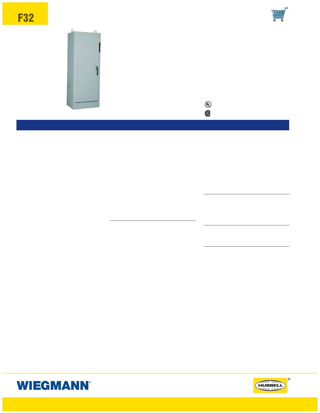
F32
WAXM-U SERIES ENCLOSURES
NEMA 12 HEAVY DUTY FREESTANDING DISCONNECT
Industry Standards
UL
CSACertified,Type12
NEMA/EEMAC Type 12
508, Type 12
UL File E64791
WA72XM2718U
FEATURES-SPECIFICATIONS
Applications
The Wiegmann universal cutout is used in
large freestand and floorstand enclosures.
Operator Adapter Kits are required in order
to install the various manufacturers’ hardware. Note that 400 A (or greater) disconnect switches and 600 A (or greater) circuit
breakers need to use the “Large” or “High
Amp” cutout, which is provided in the
WA21ABVA kit for Allen-Bradley variabledepth disconnect switches or the WA21ITE
kit for Siemens (and select other manufacturers) flex-cable devices. The “Large” or
“High Amp” cutout accepts the larger operating handle whose mounting hole centers
are 6.500-in. apart.
Allen-Bradley
• 1494V disconnect switches with flangemount variable depth operating mechanisms and 1494V flange-mounted
variable depth operating mechanisms
for circuit breakers
• 140U flexible cable operating mechanisms and 140U molded case circuit
breakers
• 1494C cable-operated disconnect
switches with flange-mount handles
• 194RC cable-operated flange-mount
handles for use with the NFPA 79 compliant 194R IEC rotary disconnect switches
Allen-Bradley 1494V-R1, -R2 and -W2 operating handles and Allen-Bradley 1494F disconnect devices or 1494D circuit breaker
operators will NOT fit these enclosures.
• ABB Controls flange-mounted variable
depth operating mechanisms for disconnect switches and circuit breakers
• Eaton Cutler-Hammer Type C361 discon-
nect switches and operator mechanisms.
Eaton Cutler-Hammer Type C371 circuit
breaker operating mechanisms. Also
Type SM safety handle mechanisms and
Flex Shaft
™
handle operators for circuit
breakers
• General Electric Type STDA flange han-
dles and variable depth operating mechanisms for disconnect switches and
circuit breakers. Also Spectra Flex
™
cable
operators for circuit breakers
™
• Siemens ITE Max-Flex
flange-mounted
variable depth operating handles for disconnect switches and circuit breakers
®
• Schnider Square D
disconnect switches
and circuit breakers used with Class 9422
flange-mounted variable depth operating
mechanisms or cable mechanism
These enclosures will not receive Class
9422 bracket-mounted disconnect
devices or Class 9422TG1 or TG2
devices
Construction
• Bodies and doors fabricated from
10 gauge steel.
• Removable 10 gauge steel back panels
are included and mounted on collar studs
• Continuously welded seams ground
smooth
• Body stiffeners provided for extra rigidity
• Heavy duty lifting eyes and provisions for
fluorescent lighting are provided
• Heavy gauge continuous hinges
support each door
• 3-point padlocking handles on all doors
• Panel supports
• Center posts are removable to permit
easy panel installation.
• Print pocket is provided
• Grounding provisions provided
• Doors are sealed with polyurethane
poured-in-place gasket
• Unless specified, the far right door is
considered to be the “Master” door. All
other doors are considered slave doors
CSA File LL66078
• The mechanical interlock is activated by
the master door which prevents the slave
doors from being opened first. Doors can
be closed in any order
• Disconnects come with a universal cutout
which provides mounting for most disconnect operators by using operator
adapters
• FTC rolled lip around all sides of enclosure opening excludes liquids and contaminants
Fini sh
• ANSI 61 gray polyester powder inside
and out over phosphatized surfaces
• Included back panels are white polyester
powder over phosphatized surfaces
Acces sories
• See pages J1-J22
• Blank adapter plates on pages F61
IMPORTANT
• Disconnect switch or circuit breakers,
operating handle and operating mechanism are not furnished with enclosure
and must be ordered separately from the
disconnect manufacturer
• Operator adapter plates are required with
this enclosure and must be purchased
separately. See pages F61 to select the
proper operator adapter for the brand
and type of disconnect being used
• Disconnect ordering information is located on page F39
• Review space occupied by disconnect
drawings on page F38 and disconnect
tables on pages F51-F60 to determine if
the disconnect device you are using will
fit the enclosure size you have selected
www.hubbell-wiegmann.com
Data Subject To Change Without Notice
Page 33
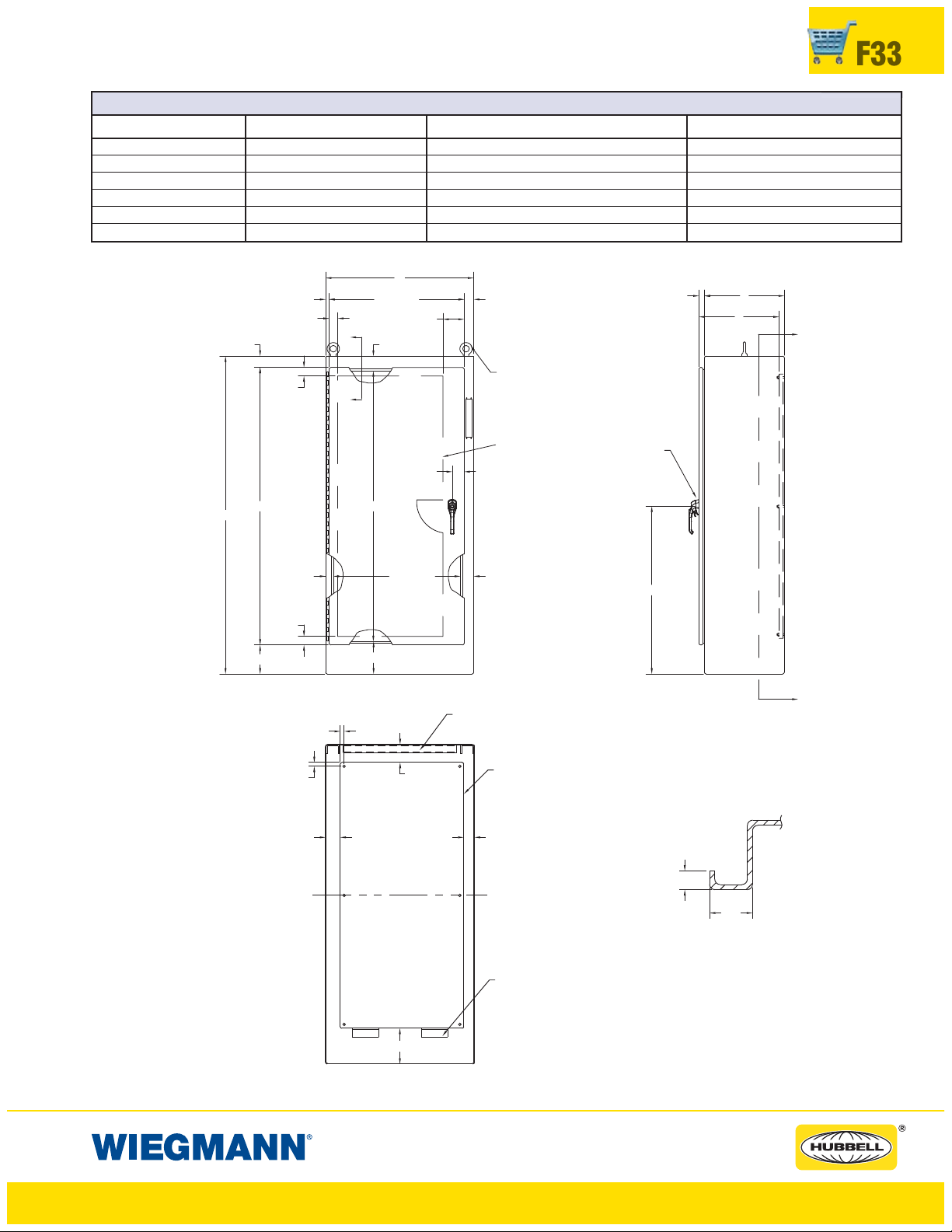
WAXM-U SERIES ENCLOSURES
NEMA 12 HEAVY DUTY FREESTANDING DISCONNECT
WAXM-U SERIES HEAVY DUTY SINGLE DOOR DISCONNECTS
CATALOG NUMBER BODY/DOOR STEEL GAUGE ENCLOSURE SIZE H X W X D BACK PANEL SIZE A X B*
WA72XM2718U 10/10 72.13x27.50x18.13 (1832x699x460) 60.00x21.75 (1524x552)
WA72XM3318U 10/10 72.13x33.50x18.13 (1832x851x460) 60.00x27.75 (1524x705)
WA72XM3918U 10/10 72.13x39.50x18.13 (1832x1003x460) 60.00x33.75 (1524x857)
WA84XM3918U 10/10 84.13x39.50x18.13 (2137x1003x460) 72.00x33.75 (1829x857)
WA90XM3920U 10/10 90.13x39.50x20.13 (2289x1003x511) 78.00x33.75 (1981x857)
WA90XM3924U 10/10 90.13x39.50x24.13 (2289x1003x613) 78.00x33.75 (1981x857)
*Back panels are furnished with enclosures.
W
1.25 D
D
HANDLE
2.56
1.94
1.94
2.19W - 3.000.81
4.81
X
3.38
LIFTING
EYE
X
CLEAR
2.69
SPACE
AVAILABLE
PADLOCKING
F33
Y
H-9.12
H
1.94
6.56
0.88
3.31 2.44
C
OF
L
PAN EL
H - 10.75
7.38
FRONT VIEW
0.88
W - 4.751.75
4.06
3.00
LIGHT BRACKET
(UNISTRUT CHANNEL)
PANEL
H/2+2.00
Y
SIDE VIEW
.438
1. 00
SECTION X-X
PAN EL
SUPPORT
8.06
SECTION Y-Y
www.hubbell-wiegmann.com
Data Subject To Change Without Notice
Page 34

F34
WAXM-U SERIES ENCLOSURES
NEMA 12 HEAVY DUTY FREESTANDING DISCONNECT
WAXM-U SERIES HEAVY DUTY TWO DOOR DISCONNECTS
CATALOG NUMBER BODY/DOOR STEEL GAUGE ENCLOSURE SIZEHXWXD BACK PANEL SIZE A X B*
WA72XM5318U 10/10 72.13x53.75x18.13 (1832x1365x460) 60.00x48.00 (1524x1219)
WA72XM6518U 10/10 72.13x65.75x18.13 (1832x1670x460) 60.00x60.00 (1524x1524)
WA72XM7718U 10/10 72.13x77.75x18.13 (1832x1975x460) 60.00x72.00 (1524x1829)
WA72XM7724U 10/10 72.13x77.75x24.13 (1832x1975x613) 60.00x72.00 (1524x1829)
WA84XM7718U 10/10 84.13x77.75x18.13 (2137x1975x461) 72.00x72.00 (1829x1829)
WA90XM7720U 10/10 90.13x77.75x20.13 (2289x1975x511) 78.00x72.00 (1981x1829)
WA90XM7724U 10/10 90.13x77.75x24.13 (2289x1975x613) 78.00x72.00 (1981x1829)
*Back panels are furnished with enclosures.
W
1.751.94
X
X
H - 10.75
W/2 - 2.38
3.38
4.814.81
2.69
LIFTING
EYE
1.94
PADLOCKING
1.25 D
D
HANDLE
0.81 2.19
2.56
W/2 - 2.38
CLEAR SPACE
AVAILABLE
Y
H-9.12
H
3.50
3.00
2.443.31
BODY STIFFENER
(OMIT IF HOR W =
56.00" OR LESS)
H/2 + 2.00
Y
SIDE VIEW
.438
1.00
SECTION X-X
6.56
PAN EL
1.94
0.88
W/2 - 4.122.50
REMOVABLE
CENTERPOST
0.88
FRONT VIEW
4.06
7.38
W/2 - 4.12
LIGHT BRACKET
(UNISTRUT CHANNEL)
8.06
SECTION Y-Y
PAN EL
SUPPORT
www.hubbell-wiegmann.com
Data Subject To Change Without Notice
Page 35

WAXM-U SERIES ENCLOSURES
NEMA 12 HEAVY DUTY FREESTANDING DISCONNECT
WAXM-U SERIES HEAVY DUTY THREE DOOR DISCONNECTS
CATALOG NUMBER BODY/DOOR STEEL GAUGE ENCLOSURE SIZE HXWXD NO.OFPANELS BACK PANEL SIZE A X B*
WA72XM3EQ18U 10/10 72.13x99.50x18.13 (1832x2527x460)
WA72XM3EW18U 10/10 72.13x117.50x18.13 (1832x2985x460)
WA84XM3EW18U 10/10 84.13x117.50x18.13 (2137x2985x460)
WA90XM3EW24U 10/10 90.13x117.50x24.13 (2289x2985x613)
*Back panels are furnished with enclosures.
1 60.00x60.00 (1524x1524)
1 60.00x27.75 (1524x705)
1 60.00x72.00 (1524x1829)
1 60.00x33.75 (1524x857)
1 72.00x72.00 (1829x1829)
1 72.00x33.75 (1829x857)
1 78.00x72.00 (1981x1829)
1 78.00x33.75 (1981x857)
F35
W
2.69W/3 - 2.67W/3- 2.67W/3 - 2.670.81
4.122.621.884.12
X
X
H - 10.75
3.38
7.38
REMOVABLE
CENTERPOST
W/3 - 4.42
4.06
2.75 TYP.
3.50
CONTINUOUS
FRONT VIEW
LIGHT BRACKET
(UNISTRUT CHANNEL)
HINGE
CLEAR SPACE
AVAILABLEON
ALL DOORS
1.94 4.81
4.50
SOLID
CENTERPOST
0.88
2.56
H - 9.12
H
6.56
8.12
LIFTING EYE
1.94
PADLOCKING
3.50W/3 - 4.42W/3 - 4.421.75
1.94
8.12
HANDLE
H/2+2.00
1.25 D
D - 1.00
SIDE VIEW
Y
Y
PAN EL
SUPPORT
0.88
.438
1.00
SECTION X-X
2.25
8.06
REMOVEABLE PANEL
(LARGE)
6.56
REMOVABLE PANEL
(SMALL)
2.94
SECTION Y-Y
www.hubbell-wiegmann.com
Data Subject To Change Without Notice
Page 36
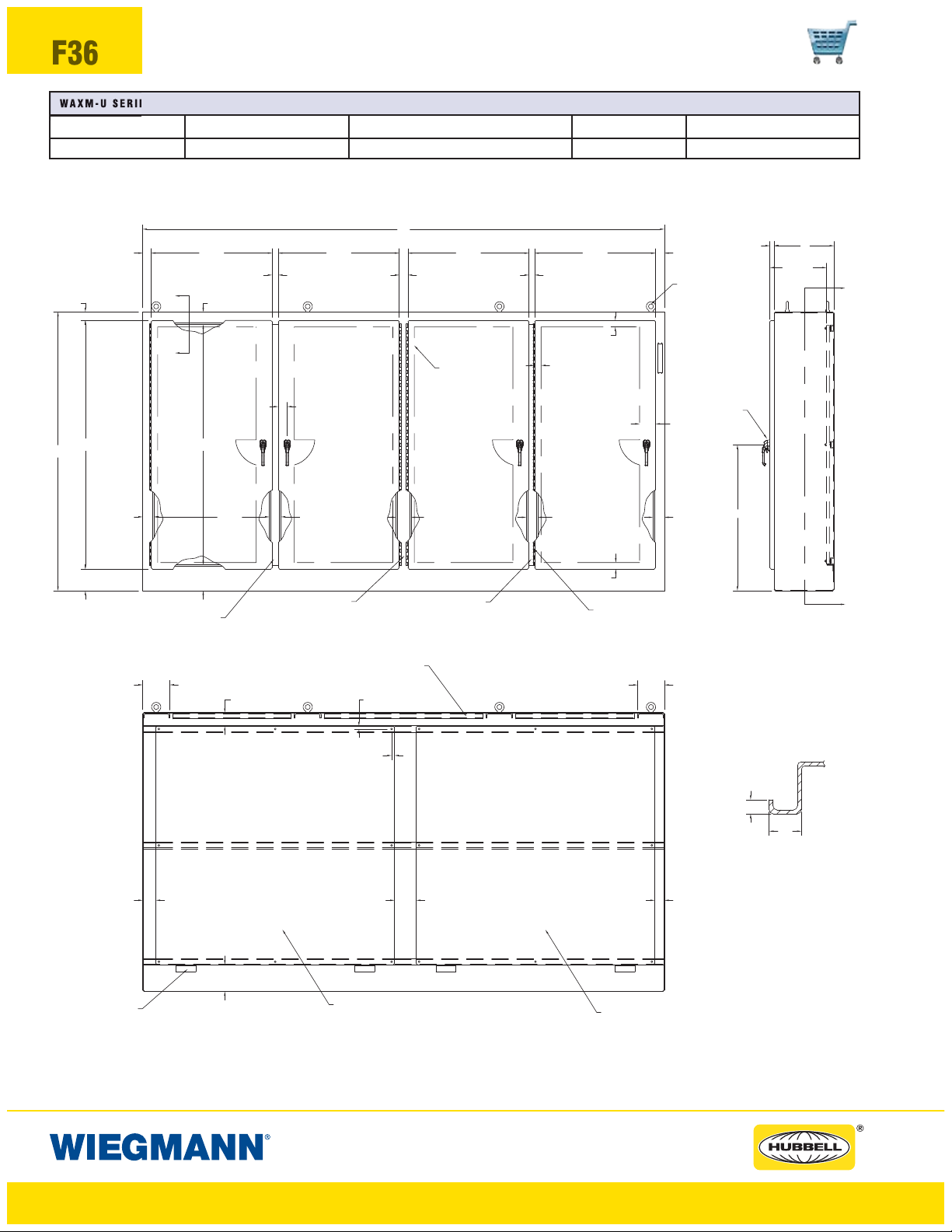
F36
WAXM-U SERIES ENCLOSURES
NEMA 12 HEAVY DUTY FOUR DOOR FREESTANDING DISCONNECT
WAXM-U SERIES HEAVY DUTY FOUR DOOR DISCONNECTS
CATALOG NUMBER BODY/DOOR STEEL GAUGE ENCLOSURE SIZE HXWXD NO.OFPANELS BACK PANEL SIZE A X B*
WA84XM4EW18U 10/10 84.13x157.50x18.13 (2137x4001x461) 2 72.00x72.00 (1829x1829)
*Back panels are furnished with enclosures.
W
1.25 D
D - 1.00
2.56
2.56
36.50
X
3.38
X
36.50
36.50
CLEAR SPACE
AVAILABLE
36.50
1.752.621.88
1.94
1.94
2.69
LIFTING
EYE
Y
2.75 TYP.
8.12
H - 10.75
7.38
REMOVABLE
CENTERPOST
34.75
TYP.
4.06
3.50
SOLID
CENTERPOST
FRONT VIEW
LIGHT BRACKETS
(UNISTRUT CHANNEL)
.88 TYP.
.88 TYP.
REMOVABLE
CENTERPOST
1.94
CONTINUOUS
HINGE
8.12
H - 9.12
H
3.50
6.56
4.81
3.503.504.50
PADLOCKING
HANDLE
H/2 + 2.00
Y
SIDE VIEW
.438
1.00
SECTION X-X
4.00
PANEL
SUPPORTS
8.06
REMOVABLE PANEL
SECTION Y-Y
2.946.56
REMOVABLE PANEL
www.hubbell-wiegmann.com
Data Subject To Change Without Notice
Page 37

WAXM-U SERIES ENCLOSURES
NEMA 12 HEAVY DUTY FREESTANDING FIVE DOOR DISCONNECT
WAXM-U SERIES HEAVY DUTY FIVE DOOR DISCONNECTS
CATALOG NUMBER BODY/DOOR STEEL GAUGE ENCLOSURE SIZE HXWXD NO.OFPANELS BACK PANEL SIZE A X B*
WA84XM5EW18U 10/10 84.13x196.75x18.13 (2137x4997x460)
*Back panels are furnished with enclosures.
W
2.56
3.38
X
2.621.882.621.88
2 72.00x72.00 (1829x1829)
1 72.00x33.75 (1829x857)
2.692.56 36.50 36.50 36.50 36.50 36.50
LIFTING
EYE
1.94
D1.25
D - 1.00
F37
Y
H - 9.12
H
3.50 3.50
6.56
8.12
X
H - 10.75
7.38
CONTINUOUS
HINGE
34.75 TYP. 4.50
REMOVABLE
CENTERPOST
.88
.88
2.75 TYP.
SOLID
CENTERPOST
FRONT VIEW
4.06
CLEAR SPACE
AVAILABLEON
ALL DOORS
3.50
REMOVABLE
CENTERPOST
LIGHT BRACKETS
(UNISTRUT CHANNEL)
1.94
4.50
SOLID
CENTERPOST
8.12
4.81
3.50
1.94
PADLOCKING
HANDLE
H/2 + 2.00
Y
SIDE VIEW
PAN EL
SUPPORTS
4.00
REMOVABLE PANEL
(LARGE)
5.50
8.06
REMOVABLE PANEL
SECTION Y-Y
(LARGE)
www.hubbell-wiegmann.com
Data Subject To Change Without Notice
6.56
2.94
REMOVABLE PANEL
(SMALL)
.438
1.00
SECTION X-X
Page 38
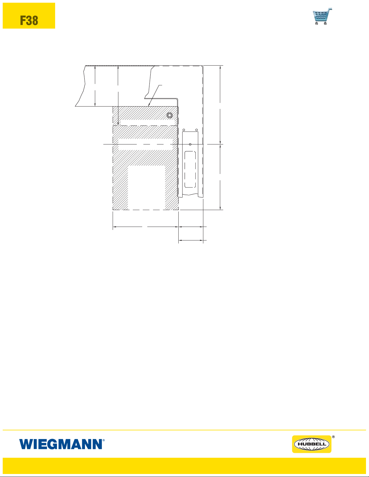
F38
WAXM-U SERIES ENCLOSURES
NEMA 12 HEAVY DUTY FREESTANDING DISCONNECT
Space Occupied by Disconnect
4.06
WB
TOP OF DISCONNECT
C
L
TOPHOLEIN
DISCONNECT HANDLE
THIS SPACE
OCCUPIED BY
DISCONNECT
SWITCH AND
FUSE CLIP
(IF USED)
OR CIRCUIT
BREAKER
G 2.44 FOR 1&2DOOR
PA NE L
E
F
2.94 FOR 3,4&5DOOR
Note:
1. See pages F51-F60 for various brands of disconnects for “E”, “F”, “G” and “WB” dimensions.
2. Disconnects will occupy space on panel shown by dimensions “E”, “F” and “G”. Wiring space “WB”
is available when disconnect is installed in the enclosure.
3. When ordering 24.13 (613mm) deep enclosures, long connecting rods must be ordered. Long
connecting rods are available from disconnect manufacturers.
• ABB Controls flange-operated devices
• Eaton Cutler-Hammer C361 devices
• Eaton Cutler-Hammer C371 operating mechanisms C371E and C371F, order catalog
number C371CS1 connecting rod. For C371G and C371K, order catalog number C371CS2
connecting rod.
• General Electric TDA devices, order catalog number TDSR extended length drive rod
• For Schneider Square D
®
9422 devices, order catalog number 9422-R2 extra long operating
rod(s). Some devices require two rods.
Refer to National Electrical Code
®
article 430-10(b) for wiring space required for line side conductors
to be connected to disconnect. Verify your application to determine if wiring space is adequate.
www.hubbell-wiegmann.com
Data Subject To Change Without Notice
Page 39

WAXM-U SERIES ENCLOSURES
NEMA 12 HEAVY DUTY FREESTANDING DISCONNECT
DISCONNECT ORDERING INFORMATION
When ordering wall-mounted disconnects from the various manufacturers, be sure to order
all of the necessary items. Each company has a different system, so care is required. Order
the following items from the disconnect manufacturer.
F39
Allen-Bradley
When using a Bulletin 1494F flangemounted disconnect switch, order:
1. A disconnect switch
2. A fuse block adapter, if required
3. Line and load connectors, if required
When using a Bulletin 1494D flange-mounted
operator for a circuit breaker, order:
1. A circuit breaker
2. A flange-mounted operating mechanism
3. A slide mechanism
When using a Bulletin 1494V disconnect
switch, order:
*1. A disconnect switch
*2. An operating handle
*3. A connecting rod (long)
*4. A trailer fuse block kit, if required
*5. A fuse clip kit, if required
6. Line and load connectors, if required
When using a Bulletin 1494V circuit
Eaton Cutler-Hammer
When using a Type C361 disconnect
switch, order:
*1. A disconnect switch with an
operating mechanism
*2. An operating handle (C361H1 or
C361H3)
When using a Type C371 circuit breaker
operating mechanism with a C-H order:
1. A circuit breaker
*2. An operating mechanism
*3. An operating handle
When using a Type SM handle mechanism,
order:
1. A circuit breaker
2. A type SM handle mechanism
When using a Flex Shaft
mechanism, order:
1. A circuit breaker
2. A complete Flex Shaft
mechanism
™
handle
™
handle
breaker operating mechanism, order:
1. A circuit breaker
2. A circuit breaker operating mechanism
3. An operating handle
4. A connecting rod (long)
ABB Controls
When using a disconnect switch, order:
1. A flange operated switch (fusible or
non-fusible)
2. A shaft [DSFHS-17 for 18.12”
(460mm) deep or DSFHS-22 for
20.12" (511mm) deep enclosures; in
24.12" (613mm) deep enclosures a
platform must be used with shaft]
3. A handle (DSFHN-HS12)
When using a circuit breaker, order:
1. A circuit breaker (ABB)
*2. An operating mechanism
*3. A shaft [FHS-17 for 18.12” (460mm)
deep or FHS-22 for 20.12" (511mm)
deep enclosures; in 24.12" (613mm)
deep enclosures a platform must be
used with shaft]
General Electric
When using a disconnect switch, order:
1. A disconnect switch (Type QMR or
QMW)
2. A fuse clip kit or no-fuse kit
3. A flange handle (STDA1 or STDA2)
4. A variable depth operating mechanism
5. An extended length drive rod
(if required)
When using a circuit breaker, order:
1. A circuit breaker
2. A flange handle (STDA1 or STDA2)
3. A variable depth operating mechanism
4. An extended length drive rod
(if required)
When using a circuit breaker with a Spectra
™
Flex
cable operator, order:
1. A circuit breaker
2. A flange-mounted handle mechanism
3. A breaker-mounted mechanism
4. An operating cable
*4. Handle mechanism (FHN-HS12)
PLEASE NOTE:
1. Various other switch accessories and circuit breaker accessories are available from disconnect manufacturers. The above information is subject to change without notice. Please
contact Hubbell-Wiegmann or the disconnect manufacturer if there are further questions.
2. The “Space Occupied” tables (pages F51-F60) are based upon information supplied by
disconnect manufacturers. Hubbell-Wiegmann does not assume responsibility for the
accuracy of these dimensions.
Siemens ITE Max-Flex
™
When using a disconnect switch, order:
1. A basic switch (right-hand)
2. A fuse or no-fuse kit
*3. FHOHS flange-mounted handle
*4. Switch operator
*5. FHOECO48 cable
When using a circuit breaker, order:
1. A circuit breaker
2. Pressure wire connectors
*3. A flange-mounted handle
*4. A circuit breaker operator mechanism
*5. An operating cable [18.12" (460mm)
deep or 20.12" (511mm) deep
enclosures accept 36.00" (914mm)
or 48.00" (1219mm) cables; 24.12"
(613mm) deep enclosures require
a 48.00" (1219mm) cable]
* These items are available from Siemens ITE Max-Flex
as a complete mechanism with a 36.00" (914mm) operating cable only. Order items separately when using a
48.00" (1219mm) operating cable.
Schneider Square D
®
When using a disconnect switch, order:
1. A disconnect switch with operating
mechanism
2. A universal handle mechanism
3. A long operating rod, if required
When using a circuit breaker, order:
1. A circuit breaker
2. An operating mechanism
3. A universal handle mechanism
4. A long operating rod, if required
When using a Class 9422 Type “T” disconnect switch with a cable mechanism, order:
1. A disconnect switch with operating
mechanism (Class 9422 Type T)
2. A handle mechanism (Class 9422
Type A-1)
3. A cable mechanism (Class 9422
CFT_O) 3-, 5-, or 10-foot
When using a circuit breaker with a cable
mechanism, order:
1. A circuit breaker (Schneider Square D
2. A handle mechanism (Class 9422
Type A-1)
3. A cable mechanism (Class 9422
CFT_O) 3-, 5-, or 10-foot
™
®
)
* Items available from disconnect manufacturer as complete kits.
www.hubbell-wiegmann.com
Data Subject To Change Without Notice
Page 40
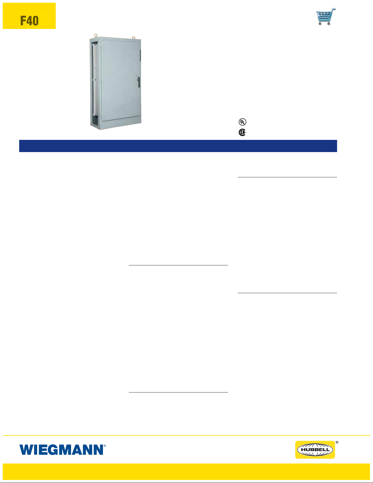
F40
WMOD SERIES ENCLOSURES
NEMA 12 MODULAR FREESTANDING DISCONNECT
Industry Standards
UL 508, Type 12
CSA Certified, Type 12
NEMA/EEMAC Type 12
UL File E64791
WMOD72X4018U
FEATURES-SPECIFICATIONS
Applications
Modular single-door and double-door Modular
free-standing enclosures are designed to be
bolted together in a variety of lengths and combinations to meet the customer’s specific application. Modular disconnects enclosures are
designed to house the following flange-mounted
disconnect switches and circuit breakers:
The Wiegmann universal cutout is used in large
freestand and floorstand enclosures. Operator
Adapter Kits are required in order to install the
various manufacturers’ hardware. Note that 400
A (or greater) disconnect switches and 600 A (or
greater) circuit breakers need to use the “Large”
or “High Amp” cutout, which is provided in the
WA21ABVA kit for Allen-Bradley variable-depth
disconnect switches or the WA21ITE kit for
Siemens ITE Max-Flex
™
(and select other manufacturers) flex-cable devices. The “Large” or
“High Amp” cutout accepts the larger operating
handle whose mounting hole centers are 6.500in. apart.
Allen-Bradley
• 1494V disconnect switches with flange-mount
variable depth operating mechanisms and
1494V flange-mounted variable depth operating mechanisms for circuit breakers
• 140U flexible cable operating mechanisms and
140U molded case circuit breakers
• 1494C cable-operated disconnect switches
with flange-mount handles
• 194RC cable-operated flange-mount handles
for use with the NFPA 79 compliant 194R IEC
rotary disconnect switches
Allen-Bradley 1494V-R1, -R2 and -W2 operating
handles and Allen-Bradley 1494F disconnect
devices or 1494D circuit breaker operators will
NOT fit these enclosures.
• ABB Controls flange-mounted variable
depth operating mechanisms for disconnect
switches and circuit breakers
• Eaton Cutler-Hammer Type C361 discon-
nect switches and operating mechanisms,
and Type C371 circuit breaker operating
mechanisms. Also Type SM safety handle
™
mechanisms and Flex Shaft
handle oper-
ators for circuit breakers
• General Electric Type STDA flange han-
dles and variable depth operating mechanisms for disconnect switches and circuit
breakers. Also Spectra Flex
tors for circuit breakers
• Siemens ITE Max-Flex
™
cable opera-
™
flange-mounted
variable depth operating handles for disconnect switches and circuit breakers
• Schneider Square D
®
disconnect switches
and circuit breakers used with Class 9422
flange-mounted variable depth operating
mechanisms or cable mechanisms
These enclosures will not receive
Schneider Square D
®
Class 9422 bracketmounted disconnect devices or Class
9422TG1 or TG2 devices.
Construction
• Bodies and doors fabricated from 10 ga. steel
• Removable 10-gauge back panels are includ-
ed and mounted on collar studs
• Continuously welded seams ground smooth
• Body stiffeners are provided for extra rigidity
• Door and side openings are flanged to provide extra strength and smooth edges
• Heavy duty lifting eyes and provisions for fluorescent lighting are provided
• Heavy gauge continuous hinges
• Grounding provisions provided
• 3-point padlocking handle on all doors
• Doors are supplied with a poured-in-place
polyurethane gasket
• Print pocket is provided
• Panel supports
• Mechanical interlocks come standard on each
enclosure. Parts required to connect interlock system between adjacent enclosures are provided
Finish
• ANSI 61 gray polyester powder inside and out
over phosphatized surfaces
• Back panels are white polyester powder over
phosphatized surfaces
CSA File LL66078
Accessories
• See pages J1-J22
• Blank adapter plates on pages F61
IMPORTANT
• Disconnect switch or circuit breakers, operating handle and operating mechanism are not
furnished with enclosure and must be ordered
separately from the disconnect manufacturer
• Operator adapter plates are required with the
modular flange disconnect enclosure only and
must be purchased separately. Modular nondisconnect enclosures do not require a operator adapter plate. See page F61 to select the
proper operator adapter for the brand and
type of disconnect being used
• Disconnect ordering information is located on
page F44
• Review space occupied by disconnect drawings on page F43 and disconnect tables on
pages F51-F60 to determine if the disconnect
device you are using will fit the enclosure size
you have selected
A modular enclosure syst em consists of:
• A disconnect (master) enclosure
• Any quantity of slave enclosures
• Gasket kits to be used between enclosures
• End plate
• An operator adapter plate or blank adapter
plate
• Disconnect device (order from disconnect
manufacturer)
Single and Two Door Enclosures
• Left side is open (see drawings on pages F41
and F42)
• Master door hinged on left
• Master door activates mechanical interlock
which prevents slave enclosures from being
opened first
• Doors may be closed in any order
Single and Two Door Slave Enclosures
• Both sides are open (see drawings on pages
F41 and F42)
• Door cannot be opened until master enclosure is opened or the interlock is defeated
www.hubbell-wiegmann.com
Data Subject To Change Without Notice
Page 41

WMOD SERIES ENCLOSURES
NEMA 12 MODULAR FREESTANDING DISCONNECT
WMOD SERIES SINGLE DOOR MODULAR FLANGE DISCONNECT (LEFT SIDE OPEN)
CATALOG NUMBER BODY/DOOR STEEL GAUGE ENCLOSURE SIZE H X W X D BACK PANEL SIZE A X B*
WMOD72X4018U 10/10 72.13x39.75x18.13 (1832x1010x460) 60.00x33.75 (1524x857)
WMOD84X4018U 10/10 84.13x39.75x18.13 (2137x1010x460) 72.00x33.75 (1829x857)
WMOD84X4024U 10/10 84.13x39.75x24.13 (2137x1010x613) 72.00x33.75 (1829x857)
WMOD SERIES SINGLE DOOR MODULAR NON-DISCONNECT (BOTH SIDES OPEN)
CATALOG NUMBER BODY/DOOR STEEL GAUGE ENCLOSURE SIZE H X W X D BACK PANEL SIZE A X B*
WMOD723818 10/10 72.13x38.75x18.13 (1832x984x460) 60.00x33.75 (1524x857)
WMOD843818 10/10 84.13x38.75x18.13 (2137x984x460) 72.00x33.75 (1829x857)
WMOD843824 10/10 84.13x38.75x24.13 (2137x984x613) 72.00x33.75 (1829x857)
*Back panels are furnished with enclosures.
Single-Door Enclosure with left side open
D
3.38
X
1.25
CONTINUOUS
HINGE
2.94
W
W-4.00 2.50
3.38
LIFTING EYES
4.06
LIGHT BRACKET
(UNISTRUT CHANNEL)
0.88
0.88
F41
2.00
2.00
CONTINUOUS
HINGE
H-9.88
H
6.94
2.00
2.94
H-9.88
H
2.00
H/2+2.00
6.94
3.69
X
1.50
H-10.75
W-5.00
7.38
PADLOCKING
HANDLE
3.00
10 GA. PANEL
INCLUDED
PANEL SUPPORTS
A
B
8.06
SECTION X-X
2.753.25
Single-Door Enclosure with both sides open
W-4.00
1.50
W
W-3.00
H-10.75
7.38
3.38
1.50
LIFTING EYES
PADLOCKING
HANDLE
2.00
H/2+2.00
3.69
2.00
D1.25
3.38
X
X
10 GA. PANEL
2.00
2.50 2.50
INCLUDED
8.06
PANEL SUPPORTS
SECTION X-X
4.06
B
0.88
0.88
A
LIGHT BRACKET
(UNISTRUT CHANNEL)
www.hubbell-wiegmann.com
Data Subject To Change Without Notice
Page 42

F42
WMOD SERIES ENCLOSURES
NEMA 12 MODULAR FREESTANDING DISCONNECT
WMOD SERIES TWO DOOR MODULAR RIGHT FLANGE DISCONNECT (LEFT SIDE OPEN)
CATALOG NUMBER BODY/DOOR STEEL GAUGE ENCLOSURE SIZEHXWXD BACK PANEL SIZE A X B*
WMOD72X7818U 10/10 72.13x78.00x18.13 (1832x1981x460) 60.00x72.00 (1524x1829)
WMOD84X7818U 10/10 84.13x78.00x18.13 (2137x1981x460) 72.00x72.00 (1829x1829)
WMOD84X7824U 10/10 84.13x78.00x24.13 (2137x1981x613) 72.00x72.00 (1829x1829)
WMOD SERIES TWO DOOR MODULAR NON-DISCONNECT (BOTH SIDES OPEN)
CATALOG NUMBER BODY/DOOR STEEL GAUGE ENCLOSURE SIZEHXWXD BACK PANEL SIZE A X B*
WMOD727718 10/10 72.13x77.00x18.13 (1832x1956x460) 60.00x72.00 (1524x1829)
WMOD847718 10/10 84.13x77.00x18.13 (2137x1956x460) 72.00x72.00 (1829x1829)
WMOD847724 10/10 84.13x77.00x24.13 (2137x1956x613) 72.00x72.00 (1829x1829)
*Back panels are furnished with enclosures.
Two-Door Right Flange Disconnect with left side open
LIFTING EYES
D
3.38
X
1.25
H/2+2.00
CONTINUOUS HINGES
1.38
2.94
H-9.88
H
2.00
3.38
W
PADLOCKING
2.63
HANDLE
W/2-4.31
OPENING
(2PL)
W/2-3.25 W/2-3.25
H-10.75
OPENING
2.50
3.00
3.25
LIGHT BRACKET
4.06
A
B
(UNISTRUT CHANNEL)
0.88
0.88
10 GA. PANEL
INCLUDED
2.75
2.00
H
2.00
H-9.88
6.94
1.38
2.00
2.94
6.94
3.69
X
7.38
REMOVABLE
CENTERPOST
8.06
PANEL SUPPORTS
SECTION X-X
Two-Door enclosure with both sides open
W/2-2.75
3.38
H-10.75
OPENING
7.38
CONTINUOUS
HINGES
W
W/2-2.75
2.75
PADLOCKING
HANDLE
W/2-3.81
OPENING
(2PL)
REMOVABLE
CENTERPOST
1.38
LIFTING
EYE
2.00
H/2+2.00
1.25
3.69
3.38
D
X
2.00
2.00
X
4.06
A
3.25
B
8.06
PANEL SUPPORTS
SECTION X-X
LIGHT BRACKET
(UNISTRUT CHANNEL)
0.88
0.88
10 GA. PANEL
INCLUDED
2.50
www.hubbell-wiegmann.com
Data Subject To Change Without Notice
Page 43

WMOD SERIES ENCLOSURES
NEMA 12 MODULAR FREESTANDING DISCONNECT
ACCESSORIES FOR MODULAR WMOD SERIES NEMA 12 FLANGE-MOUNTED DISCONNECTS
CATALOG NUMBER BODY/DOOR STEEL GAUGE SIZEHXD(SEE DRAWING BELOW)
WMOD7218EPT Formed end plate with gasket and bolts 72.13x18.13 (1832x460)
WMOD7218FTPT Flat end plate with gasket and bolts 72.00x18.50 (1829x470)
WMOD7218GK Gasket kit with gasket and bolts 72.00x18.00 (1829x457)
WMOD8418EPT Formed end plate with gasket and bolts 84.13x18.13 (2137x460)
WMOD8424EPT Formed end plate with gasket and bolts 84.13x24.13 (2137x613)
WMOD8418FTPT Flat end plate with gasket and bolts 84.00x18.50 (2134x470)
WMOD8424FTPT Flat end plate with gasket and bolts 84.00x24.50 (2134x622)
WMOD8418GK Gasket kit with gasket and bolts 84.00x18.00 (2134x457)
WMOD8424GK Gasket kit with gasket and bolts 84.00x24.00 (2134x610)
F43
DD
HHH
GASKETGASKET
2.63
Space Occupied by Disconnect
Note:
1. See pages F51-F60 for various brands of disconnects for “E”, “F”, “G” and
“WB” dimensions.
2. Disconnects will occupy space on panel shown by dimensions “E”, “F” and “G”. Wiring
space “WB” is available when disconnect is installed in the enclosure.
3. When ordering 24.13 (613mm) deep enclosures, long connecting rods must be
ordered. Long connecting rods are available from disconnect manufacturers.
• ABB Controls flange-operated devices
• Eaton Cutler-Hammer C361 devices
• Eaton Cutler-Hammer C371 operating mechanisms C371E and C371F, order
catalog number C371CS1 connecting rod . For C371G and C371K, order catalog number C371CS2 connecting rod.
• General Electric TDA devices, order catalog number TDSR extended length
drive rod
• For Schneider Square D
long operating rod(s). Some devices require two rods.
Refer to National Electrical Code
side conductors to be connected to disconnect. Verify your application
to determine if wiring space is adequate.
0.75
®
9422 devices, order catalog number 9422-R2 extra
®
article 430-10(b) for wiring space required for line
D
End Plates
Used to seal open end(s) of an assembly of modular enclosures. End plates are available
in two types:
• The 2.63" thick End Plates allow extra wiring
• The Flat End Plate provides a low profile
Gasket Kit
Used to join modular enclosures together, includes
gasket and mounting hardware.
Gasket KitFlat End PlateFlanged End Plate
TOP OF DISCONNECT
THIS SPACE IS OCCUPIED
BY DISCONNECT SWITCH
AND FUSE CLIP (IF USED)
OR CIRCUIT BREAKER.
space. The end plate includes a gasket and
mounting bolts.
cover for the open end of a modular enclosure.
The flat end plate includes gasket and mounting
bolts.
PANEL
TOP HOLE IN
DISCONNECT
HANDLE
4.06
WBWB
C
L
E
WB
F
2.75G
www.hubbell-wiegmann.com
Data Subject To Change Without Notice
Page 44
F44
WMOD SERIES ENCLOSURES
NEMA 12 MODULAR FREESTANDING DISCONNECT
DISCONNECT ORDERING INFORMATION
When ordering wall-mounted disconnects from the various manufacturers, be sure to order
all of the necessary items. Each company has a different system, so care is required. Order
the following items from the disconnect manufacturer.
Allen-Bradley
When using a Bulletin 1494F flange-mounted
disconnect switch, order:
1. A disconnect switch
2. A fuse block adapter, if required
3. Line and load connectors, if required
When using a Bulletin 1494D flange-mounted
operator for a circuit breaker, order:
1. A circuit breaker
2. A flange-mounted operating mechanism
3. A slide mechanism
When using a Bulletin 1494V disconnect
switch, order:
*1. A disconnect switch
*2. An operating handle
*3. A connecting rod (long)
*4. A trailer fuse block kit, if required
*5. A fuse clip kit, if required
6. Line and load connectors, if required
When using a Bulletin 1494V circuit
breaker operating mechanism, order:
1. A circuit breaker
2. A circuit breaker operating mechanism
3. An operating handle
4. A connecting rod (long)
ABB Controls
When using a disconnect switch, order:
1. A flange operated switch (fusible or
non-fusible)
2. A shaft [DSFHS-17 for 18.12”
(460mm) deep or DSFHS-22 for
20.12" (511mm) deep enclosures; in
24.12" (613mm) deep enclosures a
platform must be used with shaft]
3. A handle (DSFHN-HS12)
When using a circuit breaker, order:
1. A circuit breaker (ABB)
*2. An operating mechanism
*3. A shaft [FHS-17 for 18.12” (460mm)
deep or FHS-22 for 20.12" (511mm)
deep enclosures; in 24.12" (613mm)
deep enclosures a platform must be
Eaton Cutler-Hammer
When using a Type C361 disconnect
switch, order:
*1. A disconnect switch with an
operating mechanism
*2. An operating handle (C361H1 or
C361H3)
When using a Type C371 circuit breaker
operating mechanism with a C-H circuit
breaker, order:
*1. A circuit breaker
*2. An operating mechanism
*3. An operating handle
When using a Type SM handle mechanism,
order:
1. A or circuit breaker
2. A type SM handle mechanism
When using a Flex Shaft
™
handle
mechanism, order:
1. A circuit breaker
2. A complete Flex Shaft™handle
mechanism
General Electric
When using a disconnect switch, order:
1. A disconnect switch (Type QMR or
QMW)
2. A fuse clip kit or no-fuse kit
3. A flange handle (STDA1 or STDA2)
4. A variable depth operating mechanism
5. An extended length drive rod
When using a circuit breaker, order:
1. A circuit breaker
2. A flange handle (STDA1 or STDA2)
3. A variable depth operating mechanism
4. An extended length drive rod
When using a circuit breaker with a Spectra
™
Flex
cable operator, order:
1. A circuit breaker
2. A flange-mounted handle mechanism
3. A breaker-mounted mechanism
4. An operating cable
used with shaft]
*4. Handle mechanism (FHN-HS12)
PLEASE NOTE:
1. Various other switch accessories and circuit breaker accessories are available from disconnect manufacturers. The above information is subject to change without notice. Please
contact Hubbell-Wiegmann or the disconnect manufacturer if there are further questions.
2. The “Space Occupied” tables (pages F51-F60) are based upon information supplied by
disconnect manufacturers. Hubbell-Wiegmann does not assume responsibility for the
accuracy of these dimensions.
Siemens ITE Max-Flex
™
When using a disconnect switch, order:
1. A basic switch (right-hand)
2. A fuse or no-fuse kit
*3. FHOHS flange-mounted handle
*4. Switch operator
*5. FHOECO48 cable
When using a circuit breaker, order:
1. A circuit breaker
2. Pressure wire connectors
*3. A flange-mounted handle
*4. A circuit breaker operator mechanism
*5. An operating cable [18.12" (460mm)
deep or 20.12" (511mm) deep
enclosures accept 36.00" (914mm)
or 48.00" (1219mm) cables; 24.12"
(613mm) deep enclosures require
a 48.00" (1219mm) cable]
* These items are available from Siemens ITE Max-Flex
as a complete mechanism with a 36.00" (914mm) operating cable only. Order items separately when using a
48.00" (1219mm) operating cable.
Schneider Square D
®
When using a disconnect switch, order:
1. A disconnect switch with operating
mechanism
2. A universal handle mechanism
3. A long operating rod, if required
When using a circuit breaker, order:
1. A circuit breaker
2. An operating mechanism
3. A universal handle mechanism
4. A long operating rod, if required
When using a Class 9422 Type “T” disconnect switch with a cable mechanism, order:
1. A disconnect switch with operating
mechanism (Class 9422 Type T)
2. A handle mechanism (Class 9422
Type A-1)
3. A cable mechanism (Class 9422
CFT_O) 3-, 5-, or 10-foot
When using a circuit breaker with a cable
mechanism, order:
1. A circuit breaker (Schneider Square D
2. A handle mechanism (Class 9422
Type A-1)
3. A cable mechanism (Class 9422
CFT_O) 3-, 5-, or 10-foot
™
®
)
* Items available from disconnect manufacturer as complete kits.
www.hubbell-wiegmann.com
Data Subject To Change Without Notice
Page 45
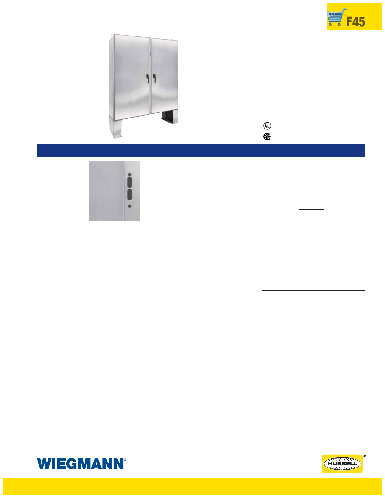
WAX-SSN4 & WACPX-SSN4 ENCLOSURES
NEMA 4X TWO DOOR FLOOR MOUNT DISCONNECT
Industry Standards
UL 508, Types 4, 4X & 12
CSA Certified, Type 12
NEMA/EEMAC Types 4, 4X & 12
(UL4&4XpendingonCPXversion)
UL File E64791
F45
WA72X7312SSN4
FEATURES-SPECIFICATIONS
Applications
Enclosure having
the “WM” preferred
cutout are sized for
use with up to 200A
disconnect switches
and up to 400A circuit breakers unless
otherwise specified.
The “WM” preferred
cutout accepts the
smaller operating
handle whose mounting hole centers are
“WM” PREFERRED
CUTOUT
for WAXSSN4 &
WACPXSSN4
4.677 in. apart. “WM” preferred cutouts are
standard in mild steel wall-mount enclosures, modular enclosures and some select
large mild steel and standard stainless steel
offerings.
“WM” preferred cutout are designed to
house the following:
Allen-Bradley
• 1494V disconnect switches with flangemount variable depth operating mechanisms and 1494V flange-mounted
variable depth operating mechanisms
for circuit breakers
• 140U flexible cable operating mechanisms and 140U molded case circuit
breakers
• 1494C cable-operated disconnect
switches with flange-mount handles
• 194RC cable-operated flange-mount
handles for use with the NFPA 79 compliant 194R IEC rotary disconnect switches
Allen-Bradley 1494V-R1, -R2 and -W2 operating handles and Allen-Bradley 1494F disconnect devices or 1494D circuit breaker
operators will NOT fit these enclosures.
• ABB Controls flange-mounted variable
depth operating mechanisms for disconnect switches and circuit breakers. Also
the cable version for circuit breakers.
• Eaton Cutler-Hammer Type C361 flange-
mount variable depth operating mecha-
nisms with disconnect switches and Type
C371 flange-mount variable-depth operating mechanisms for circuit breakers.
• General Electric Type STDA flange han-
dles and variable depth operating mechanisms for disconnect switches and
circuit breakers. Also Spectra Flex
™
cable
operators for circuit breakers
™
• Siemens ITE Max-Flex
flange-mounted
variable depth operating handles for circuit breakers
®
• Schneider Square D
Class 9422 disconnect switches with flange-mounted variable depth operating mechanisms or
cable mechanisms and Class 9422
flange-mount variable-depth operating
mechanism or cable mechanisms for circuit breakers.
These enclosures will not accept
Schneider Square D
®
Class 9422 bracket-mounted disconnect devices, Class
9422TG1 or TG2 devices.
All 24.12 in. and deeper enclosures using
short connecting rods by the following
manufacturers
• ABB Controls flange-operated devices
• Eaton Cutler-Hammer C361 devices
• Eaton Cutler-Hammer C371 mechanisms
which use C371E, F, G, K operating
mechanism (see Disconnect Enclosure
Accessories)
• General Electric Type TDA devices (see
Disconnect enclosure Accessories)
• Schneider Square D Class 9422 devices
(see Disconnect enclosure Accessories)
Require long connecting rods order ed in
place of short connecting rods.
• For Eaton Cutler-Hammer operating
mechanisms C371E and C371F order catalog number C371CS1 connecting rod.
For C371G and C371K order catalog
number C371CS2 connecting rod.
CSA File LL66078
• For General Electric devices, order
catalog number TDSR extended length
drive rod
• For Schneider Square D devices, order
catalog number 9422-R2 extra long operating rod(s). Some devices require two rods.
IMPORTANT Ordering Information
• Disconnect switch or circuit breakers,
operating handle and operating mechanism are not furnished with the enclosure
and must be ordered separately from the
disconnect manufacturer
• Disconnect ordering information is
located on page F50
• Review space occupied by disconnect
drawings on page F46 and disconnect
tables on pages F51-F60 to determine if
the disconnect device you are using will
fit the enclosure size you have selected
Construction
• Bodies and doors fabricated from
12 & 10 gauge 304 stainless steel.
• Continuously welded seams ground
smooth
• Body stiffeners provided for extra rigidity
• Heavy gauge continuous hinges to
secure doors
• Heavy duty 3-PT 316L SS padlocking
handles on all doors
• Print pocket is provided
• 15-inch floor stands are welded to
enclosure
• Doors are sealed with polyurethane
poured-in-place gasket
• Heavy duty lifting eyes and provisions
for fluorescent lighting are provided
• Panel supports
• Collar studs are provided for mounting
optional sub panels
• Grounding provisions provided
www.hubbell-wiegmann.com
Data Subject To Change Without Notice
Page 46

F46
WAX-SSN4 & WACPX-SSN4 ENCLOSURES
NEMA 4X TWO DOOR FLOOR MOUNT DISCONNECT
• Unless specified, the right door in considered to be the “master” door on the
“Right Flange” mount enclosures and the
left door is the “master” door on the
“Center Post” mount enclosures.
• A mechanical interlock is provided and
prevents the slave door from opening
before opening the master door
• Disconnects come with a universal
disconnectsoperatorsbyusingoperator
adapters
• Removable center post permits easy
panel installation
Finish
• Except for back, exterior has standard
grained finish, interior has standard
commercial finish
cutout which provides mounting for most
WAX-SSN4 ENCLOSURES NEMA 4X TWO DOOR RIGHT FLANGE DISCONNECT
CATALOG NUMBER
WA60X4912SSN4 60.12x49.75x12.12 (1527x1264x308) NPDD6048 NPDD6048G 56.00x44.00 (1422x1118)
WA60X4918SSN4 60.12x49.75x18.12 (1527x1264x460) NPDD6048 NPDD6048G 56.00x44.00 (1422x1118)
WA60X6112SSN4 60.12x61.75x12.12 (1527x1568x308) NPDD6060 NPDD6060G 56.00x56.00 (1422x1422)
WA60X6118SSN4 60.12x61.75x18.12 (1527x1568x460) NPDD6060 NPDD6060G 56.00x56.00 (1422x1422)
WA72X6112SSN4 72.12x61.75x12.12 (1832x1568x308) NPDD7260 NPDD7260G 68.00x56.00 (1727x1422)
WA72X6118SSN4 72.12x61.75x18.12 (1832x1568x460) NPDD7260 NPDD7260G 68.00x56.00 (1727x1422)
WA72X7312SSN4 72.12x73.75x12.12 (1832x1873x308) NPDD7272 NPDD7272G 68.00x68.00 (1727x1727)
WA72X7318SSN4 72.12x73.75x18.12 (1832x1873x460) NPDD7272 NPDD7272G 68.00x68.00 (1727x1727)
WA72X7324SSN4 72.12x73.75x24.12 (1832x1873x613) NPDD7272 NPDD7272G 68.00x68.00 (1727x1727)
WACPX-SSN4 ENCLOSURES NEMA 4X TWO DOOR CENTERPOST FLOOR MOUNT DISCONNECT
CATALOG NUMBER
WA60CPX4812SSN4 60.12x48.50x12.12 (1527x1273x308 NPDD6048 NPDD6048G 56.00x44.00 (1422x1118)
WA60CPX6012SSN4 60.12x60.50x12.12 (1527x1273x308) NPDD6060 NPDD6060G 56.00x56.00 (1422x1422)
WA72CPX7212SSN4 72.12x72.50x12.12 (1832x1273x308) NPDD7272 NPDD7272G 68.00x68.00 (1728x1728)
WA72CPX7218SSN4 72.12x72.50x18.12 (1832x1273x460) NPDD7272 NPDD7272G 68.00x68.00 (1728x1728)
*Back panels must be ordered separately. Panels are made from 10 gauge steel.
2.06
WB
PAN EL
TOP OFDISCONNECT
TOP HOLE IN
C
L
DISCONNECT HANDLE
THIS SPACE
OCCUPIED BY
DISCONNECT
SWITCH AND
FUSE CLIP
(IF USED)
OR CIRCUIT
BREAKER
"WAX-SSN4"Style Enclosures "WACPX-SSN4"Style Enclosure
“WAX-SSN4” Style Enclosures “WACPX-SSN4” Style Enclosures
C
L
1.31
2.44G
ENCLOSURE SIZE BACKPANEL CATALOG NUMBER* BACKPANEL
HXWXD
WHITE “G”
ENCLOSURE SIZE BACKPANEL CATALOG NUMBER* BACKPANEL
E
F
HXWXD
2.06
C
L
WB
PAN EL
TOP OFDISCONNECT
TOP HOLEIN
DISCONNECT HANDLE
THIS SPACE
OCCUPIED BY
DISCONNECT
SWITCH AND
FUSE CLIP
(IF USED)
OR CIRCUIT
BREAKER
C
OF PANEL
L
G+1.18 K
WHITE “G”
C
L
1.92
• Optional back panels are white polyester
powder over phosphatized surfaces
• Optional “G” panels have a conductive
finish
Acces sories
• See pages J1-J22
• Blank adapter plates on pages F61
SIZE A X B
SIZE A X B
Note:
1. See pages F51-F60 for various brands of
disconnects for “E”,“F”,“G”, “K” and “WB”
dimensions.
2. Disconnects will occupy space on panel
E
F
shown by dimensions “E”,“F”, “G” and “K”.
Wiring space “WB” is available when disconnect is installed in the enclosure.
3. When ordering 24.13 (613mm) deep enclosures, long connecting rods must be
ordered. Long connecting rods are available from disconnect manufacturers.
• ABB Controls flange-operated devices
• Eaton Cutler-Hammer C361 devices
• Eaton Cutler-Hammer C371 operating
mechanisms C371E and C371F, order
catalog number C371CS1 connecting rod.
For C371G and C371K, order catalog
number C371CS2 connecting rod.
• General Electric TDA devices, order
catalog number TDSR extended length
drive rod
• For Schneider Square D
®
9422 devices,
order catalog number 9422-R2 extra long
operating rod(s). Some devices require two
rods.
Refer to National Electrical Code
®
article 43010(b) for wiring space required for line side
conductors to be connected to disconnect. Verify
your application to determine if wiring space is
adequate.
www.hubbell-wiegmann.com
Data Subject To Change Without Notice
Page 47

WAX-SSN4 & WACPX-SSN4 ENCLOSURES
NEMA 4X TWO DOOR FLOOR MOUNT DISCONNECT
F47
WAX-SSN4
.69
1.94
H -1.38H
1.94
.69
15.00
WACPX-SSN4
0.81
.69
1.94
H -1.38H
1.94
.69
15.00
W/2 -4.13 W/2 - 4.131.75
REMOVABLE
CENTER POST
W/2 -3.50 W/2 - 3.501.75
3.50
FRONT VIEW
REMOVABLE
CENTER POST
FRONT VIEW
W
W
1.75 2.190.81
1.94
1.50
H -3.00
1.50
CONTINUOUS
HINGE
3.50
3.00
TYP.
W/2 -2.38W/2- 2.38
PADLOCKING
HANDLE
H/2 +15.00"
PADLOCKING
HANDLE
H/2 +15.00"
1.25 D
SIDE VIEW
1.25 D
SIDE VIEW
Y
D
.438
1.00
SECTION X-X
Y
Y
D
.438
1.00
SECTION X-X
Y
LIGHT BRACKET
2.06
(UNISTRUT CHANNEL)
2.06
A
C
L
B
2.44
C
L
4.814.811.94
X
X
3.00
2.69
TYP.
LIFTING
EYE
CLEAR
SPACE
AVAILABLE
OPTIONAL
BODY STIFFENER
(NOT PROVIDEDIF
H ORW = 56.00"
SUPPORT
0.88
0.88
3.31
PANEL
OR LESS)
PANE L
SECTION Y-Y
W/2 -1.75W/2 -1.75
X
1.50
X
H -3.00
1.50
0.811.88
1.944.814.811.94
1.75
CLEAR
SPACE
AVAILABLE
CONTINUOUS
HINGE
OPTIONAL
PANE L
BODY STIFFENER
(NOT PROVIDEDIF
H ORW = 56.00"
OR LESS)
PANEL
SUPPORT
0.88
0.88
3.31
2.06
LIGHT BRACKET
(UNISTRUT CHANNEL)
2.06
A
C
L
B
2.44
C
L
SECTION Y-Y
www.hubbell-wiegmann.com
Data Subject To Change Without Notice
Page 48

F48
WAXM-SSN4 ENCLOSURES
NEMA 4X TWO DOOR FLOOR MOUNT DISCONNECT
Industry Standards
UL 508, Type 3R, 4, 4X & 12
CSA Certified, Type 12
NEMA/EEMAC Type 3R, 4, 4X & 12
Single Door Rating Pending UL (Ref: 4 & 4X)
UL File E64791
WA72XM2818SSN4
FEATURES-SPECIFICATIONS
Applications
Enclosure having
the “WM” preferred
cutout are sized for
usewithupto200A
disconnect switches
and up to 400A circuit breakers unless
otherwise specified.
The “WM” preferred
cutout accepts the
smaller operating
handle whose mount-
“WM” PREFERRED
CUTOUT
WAXM-SSNR
ing hole centers are
4.677 in. apart. “WM” preferred cutouts are
standard in mild steel wall-mount enclosures, modular enclosures and some select
large mild steel and standard stainless steel
offerings.
See Page F45 for Allen-Bradley, ABB,
Eaton Cutler Hammer, General Electric,
Siemens ITE & Schneider Square D
options.
IMPORTANT Ordering Information
• Disconnect switch or circuit breakers,
operating handle and operating mechanism are not furnished with the enclosure
and must be ordered separately from the
disconnect manufacturer
• Disconnect ordering information is
located on page F50
• Review space occupied by disconnect
drawings on page F30 and disconnect
tables on pages F51-F60 to determine if
the disconnect device you are using will
fit the enclosure size you have selected
Construction
• Bodies and doors fabricated from
12 & 10 gauge 304 stainless steel.
• Removable 10 gauge steel back panels
are included and mounted on collar studs
• Continuously welded seams ground
smooth
• Body stiffeners provided for extra rigidity
• Heavy gauge continuous hinges to support each door
• Heavy duty lifting eyes and provisions for
fluorescent lighting are provided
• 3-PT 316L SS padlocking handles on all
doors
• Panel supports
• Center posts are removable to permit
easy panel installation
• Print pocket is provided
• Grounding provisions provided
• Doors are sealed with polyurethane
poured-in-place gasket
• Unless specified, the far right door in
considered to be the “master” door. All
other doors are considered slave doors.
• The mechanical interlock is activated by
the master door which prevents the slave
doors from being opened first. Doors can
be closed in any order
• Disconnects come with a universal
cutout which provides mounting for most
disconnect operators by using operator
adapters
Finish
• Except for back, exterior has a standard
grained finish
• Included back panels are white polyester
powder over phosphatized surfaces
Accessories
•SeepagesJ1-J22
• Back panels (see reference tables)
CSA File LL66078
Space Occupied by Disconnect
4.06
WB
TOPOFDISCONNECT
TOP HOLEIN
C
L
DISCONNECT HANDLE
Note:
1. See pages F51-F60 for various brands of
disconnects for “E”, “F”, “G” and “WB” dim.
2. Disconnects will occupy space on panel
shown by dimensions “E”, “F” and “G”.
Wiring space “WB” is available when disconnect is installed in the enclosure.
3. When ordering 24.13 (613mm) deep
enclosures, long connecting rods must
be ordered. Long connecting rods are
available from disconnect manufacturers.
• ABB Controls flange-operated devices
• Eaton Cutler-Hammer C361 devices
• Eaton Cutler-Hammer C371 operating
mechanisms C371E and C371F, order
catalog number C371CS1 connecting
rod. For C371G and C371K, order catalog number C371CS2 connecting rod.
• General Electric TDA devices, order
catalog number TDSR extended length
drive rod
• For Schneider Square D
devices, order catalog number 9422R2 extra long operating rod(s). Some
devices require two rods.
Refer to National Electrical Code
430-10(b) for wiring space required for line
side conductors to be connected to disconnect. Verify your application to determine if
wiring space is adequate.
PANEL
THIS SPACE
OCCUPIED BY
DISCONNECT
SWITCH AND
FUSE CLIP
(IF USED)
OR CIRCUIT
BREAKER
”WAXM-SSN4”Style Enclosure
C
L
®
9422
®
1.31FOR1&2DOOR
2.44FOR1&2DOORG
article
E
F
www.hubbell-wiegmann.com
Data Subject To Change Without Notice
Page 49

WAXM-SSN4 SERIES ENCLOSURES NEMA 4X RIGHT FLANGE
SINGLE & DOUBLE DOOR FREESTANDING DISCONNECT
WAXM-SSN4 ENCLOSURES NEMA 4X ONE DOOR RIGHT FLANGE FREESTANDING HANDLE DISCONNECT
CATALOG NUMBER SIZE H X W X D BACK PANEL SIZE A X B
WA72XM2718SSN4 72.12x27.50x18.12 (1832x718x460) 60.00x21.75 (1524x552)
WA72XM3318SSN4 72.12x33.50x18.12 (1832x870x460) 60.00x27.75 (1524x705)
WA72XM3918SSN4 72.12x39.50x18.12 (1832x1022x460) 60.00x33.75 (1524x857)
WA84XM3918SSN4 84.12x39.50x18.12 (2137x1022x460) 72.00x33.75 (1829x857)
WA84XM3924SSN4 84.12x39.50x24.12 (2137x1022x613) 78.00x33.75 (1981x857)
WA90XM3918SSN4 90.12x40.25x18.12 (2289x1022x460) 79.00x33.75 (2007x857)
WA90XM3920SSN4 90.12x40.25x20.12 (2289x1022x511) 80.00x33.75 (2032x857)
WA90XM3924SSN4 90.12x40.25x24.12 (2289x1022x613) 81.00x33.75 (2057x857)
WA-XM-SSN4 ENCLOSURES NEMA 4X TWO DOOR RIGHT FLANGE FREESTANDING DISCONNECT
CATALOG NUMBER BODY/DOOR 304 SS BACK PANEL SIZE A X B
WA72XM5318SSN4 72.12x53.75x18.12 (1832x1384x460) 60.00x48.00 (1524x1219)
WA72XM6518SSN4 72.12x65.75x18.12 (1832x1689x460) 60.00x60.00 (1524x1524)
WA72XM7718SSN4 72.12x77.75x18.12 (1832x1994x460) 60.00x72.00 (1524x1829)
WA72XM7724SSN4 72.12x77.75x24.12 (1832x1994x613) 60.00x72.00 (1524x1829)
WA84XM7718SSN4 84.12x77.75x18.12 (2137x1022x460) 72.00x72.00 (1829x1829)
WA84XM7724SSN4 84.12x77.75x24.12 (2137x1022x613) 72.00x72.00 (1829x1829)
WA90XM7718SSN4 90.12x77.75x18.12 (2289x1994x460) 78.00x72.00 (1981x1829)
WA90XM7720SSN4 90.12x77.75x20.12 (2289x1994x511) 78.00x72.00 (1981x1829)
WA90XM7724SSN4 90.12x77.75x24.12 (2289x1994x613) 78.00x72.00 (1981x1829)
*Back panels must be ordered separately. Panels are made from 10 gauge steel.
F49
1.94
1.94
1.94
W/2- 2.38
CLEARSPACE
AVAILAB LE
W/2- 4.122.50
REMOVABLE
CENTERPOST
X
X
H -10.75
7.38
3.50
FRONT VIEW
2.56
H -9.12
H
6.56
0.81 2.19
2.56
H- 9.12
H
1.94
6.56
W
3.38
W -4.751.75
FRONT VIEW
W
1.751.94
X
X
H- 10.75
LIFTING
EYE
CLEAR
SPACE
AVAILABLE
1.94
2.69
3.00
H/2 +2.00
LIFTING
EYE
1.25 D
PADLOCKING
HANDLE
PADLO CKING
HANDLE
H/2+ 2.00
SIDE VIEW
1.25 D
SIDE VIEW
8.06
4.06
4.06
8.06
SECTION Y-Y
LIGHT BRACKET
(UNISTRUTCHANNEL)
PAN EL
PAN EL
SUPPORT
LIGHTBRACKET
(UNISTRUTCHANNEL)
.438
1.00
SECTION X-X
2.443.31
BODYSTIFFENER
(OMITIF HOR W =
56.00"OR LESS)
PANEL
SUPPORT
.438
1.00
SECTION X-X
D
Y
C
L
PAN EL
Y
D
Y
Y
0.88
0.88
3.31 2.44
OF
SECTION Y-Y
0.88
0.88
PANEL
2.19W -3.000.81
4.81
2.69
3.00
W/2- 2.38
4.814.81
3.38
W/2- 4.12
7.38
www.hubbell-wiegmann.com
Data Subject To Change Without Notice
Page 50

F50
WAX-SSN4, WAXM-SSN4 & WACPX-SSN4 SERIES ENCLOSURES
NEMA 4X RIGHT FLANGE FREESTANDING DISCONNECT
DISCONNECT ORDERING INFORMATION
When ordering wall-mounted disconnects from the various manufacturers, be sure to order
all of the necessary items. Each company has a different system, so care is required. Order
the following items from the disconnect manufacturer.
Allen-Bradley
When using a Bulletin 1494F flange-mounted disconnect switch, order:
1. A disconnect switch
2. A fuse block adapter, if required
3. Line and load connectors, if required
When using a Bulletin 1494D flange-mounted operator for a circuit breaker, order:
1. A circuit breaker
2. A flange-mounted operating mechanism
3. A slide mechanism
When using a Bulletin 1494V
disconnect
switch, order:
*1. A disconnect switch
*2. An operating handle
*3. A connecting rod (long)
*4. A trailer fuse block kit, if required
*5. A fuse clip kit, if required
6. Line and load connectors, if required
When using a Bulletin 1494V circuit
breaker operating mechanism, order:
1. A circuit breaker
2. A circuit breaker operating mechanism
3. An operating handle
4. A connecting rod (long)
ABB Controls
When using a disconnect switch, order:
1. A flange operated switch (fusible or
non-fusible)
2. A shaft [DSFHS-17 for 18.12”
(460mm) deep or DSFHS-22 for
20.12" (511mm) deep enclosures; in
24.12" (613mm) deep enclosures a
platform must be used with shaft]
3. A handle (DSFHN-HS12)
When using a circuit breaker, order:
1. A circuit breaker (ABB)
*2. An operating mechanism
*3. A shaft [FHS-17 for 18.12” (460mm)
deep or FHS-22 for 20.12" (511mm)
deep enclosures; in 24.12" (613mm)
deep enclosures a platform must be
Eaton Cutler-Hammer
When using a Type C361 disconnect
switch, order:
*1. A disconnect switch with an
operating mechanism
*2. An operating handle (C361H1 or
C361H3)
When using a Type C371 circuit breaker
operating mechanism with a C-H circuit
breaker, order:
*1. A circuit breaker
*2. An operating mechanism
*3. An operating handle
When using a Type SM handle mechanism,
order:
1. A circuit breaker
2. A type SM handle mechanism
When using a Flex Shaft
™
handle
mechanism, order:
1. A circuit breaker
2. A complete Flex Shaft™handle
mechanism
General Electric
When using a disconnect switch, order:
1. A disconnect switch (Type QMR or
QMW)
2. A fuse clip kit or no-fuse kit
3. A flange handle (STDA1 or STDA2)
4. A variable depth operating mechanism
5. An extended length drive rod
When using a circuit breaker, order:
1. A circuit breaker
2. A flange handle (STDA1 or STDA2)
3. A variable depth operating mechanism
4. An extended length drive rod
When using a circuit breaker with a Spectra
™
Flex
cable operator, order:
1. A circuit breaker
2. A flange-mounted handle mechanism
3. A breaker-mounted mechanism
4. An operating cable
used with shaft]
*4. Handle mechanism (FHN-HS12)
PLEASE NOTE:
1. Various other switch accessories and circuit breaker accessories are available from disconnect manufacturers. The above information is subject to change without notice. Please
contact Hubbell-Wiegmann or the disconnect manufacturer if there are further questions.
2. The “Space Occupied” tables (pages F51-F60) are based upon information supplied by
disconnect manufacturers. Hubbell-Wiegmann does not assume responsibility for the
accuracy of these dimensions.
Siemens ITE Max-Flex
™
When using a disconnect switch, order:
1. A basic switch (right-hand)
2. A fuse or no-fuse kit
**3. FHOHS flange-mounted handle
**4. Switch operator
**5. FHOECO48 cable
When using a circuit breaker, order:
1. A circuit breaker
2. Pressure wire connectors
**3. A flange-mounted handle
**4. A circuit breaker operator mechanism
**5. An operating cable [18.12" (460mm)
deep or 20.12" (511mm) deep
enclosures accept 36.00" (914mm)
or 48.00" (1219mm) cables; 24.12"
(613mm) deep enclosures require
a 48.00" (1219mm) cable]
** These items are available from Siemens ITE Max-Flex
as a complete mechanism with a 36.00" (914mm)
operating cable only. Order items separately when
using a 48.00" (1219mm) operating cable.
Schneider Square D
®
When using a disconnect switch, order:
1. A disconnect switch with operating
mechanism
2. A universal handle mechanism
3. A long operating rod, if required
When using a circuit breaker, order:
1. A circuit breaker
2. An operating mechanism
3. A universal handle mechanism
4. A long operating rod, if required
When using a Class 9422 Type “T” disconnect switch with a cable mechanism, order:
1. A disconnect switch with operating
mechanism (Class 9422 Type T)
2. A handle mechanism (Class 9422
Type A-1)
3. A cable mechanism (Class 9422
CFT_O) 3-, 5-, or 10-foot
When using a circuit breaker with a cable
mechanism, order:
1. A circuit breaker (Schneider Square D
2. A handle mechanism (Class 9422
Type A-1)
3. A cable mechanism (Class 9422
CFT_O) 3-, 5-, or 10-foot
™
®
)
* Items available from disconnect manufacturer as complete kits.
www.hubbell-wiegmann.com
Data Subject To Change Without Notice
Page 51

FLOOR-MOUNT • FREESTANDING • MODULAR SERIES ENCLOSURES
DISCONNECT SPACE OCCUPIED & AVAILABLE WIRING SPACE INFORMATION
F51
ALLEN-BRADLEY TYPE 1494F DISCONNECT SWITCHES
TYPE AMP FUSE FUSE
NUMBER RATING CLIP CLASS
N30 30A No fuse — 4.62 6.50 0.99 5.31 11.31 9.31 15.31 18.31
NF30 30A 30A-250V H, K, R 6.50 6.50 0.99 5.31 11.31 9.31 15.31 18.31
NF30 30A 60A-250V H, K, R 7.25 6.50 0.99 5.31 11.31 9.31 15.31 18.31
NF30 30A 30A-600V H, K, R 9.25 6.50 0.99 5.31 11.31 9.31 15.31 18.31
NF30 30A 60A-600V H, K, R 9.75 6.50 0.99 5.31 11.31 9.31 15.31 18.31
NF30 30A 30A-600V J 6.50 6.50 0.99 5.31 11.31 9.31 15.31 18.31
NF30 30A 60A-600V J 6.62 6.50 0.99 5.31 11.31 9.31 15.31 18.31
N60 60A No fuse — 4.62 6.50 0.99 4.62 10.62 8.62 14.62 17.62
NF60 60A 30A-600V H, K, R 10.38 6.50 0.99 4.62 10.62 8.62 14.62 17.62
NF60 60A 60A-250V H, K, R 8.38 6.50 0.99 4.62 10.62 8.62 14.62 17.62
NF60 60A 100A-250V H, K, R 10.88 6.50 0.99 4.62 10.62 8.62 14.62 17.62
NF60 60A 60A-600V H, K, R 10.88 6.50 0.99 4.62 10.62 8.62 14.62 17.62
NF60 60A 100A-600V H, K, R 12.88 6.62 0.99 4.62 10.62 8.62 14.62 17.62
NF60 60A 60A-600V J 7.75 6.50 0.99 4.62 10.62 8.62 14.62 17.62
NF60 60A 100A-600V J 9.75 6.50 0.99 4.62 10.62 8.62 14.62 17.62
N100 100A No fuse — 4.62 7.25 0.99 — 8.75 6.75 12.75 15.75
NF100 100A 100A-250V H, K, R 11.38 7.38 0.99 — 8.75 6.75 12.75 15.75
NF100 100A 200A-250V H, K, R 12.25 7.62 0.99 — 8.75 6.75 12.75 15.75
NF100 100A 100A-600V H, K, R 13.38 7.50 0.99 — 8.75 6.75 12.75 15.75
NF100 100A 200A-600V H, K, R 14.75 7.75 0.99 — 8.75 6.75 12.75 15.75
NF100 100A 100A-600V J 10.12 7.38 0.99 — 8.75 6.75 12.75 15.75
NF100 100A 200A-600V J 10.88 7.50 0.99 — 8.75 6.75 12.75 15.75
N200 200A No fuse — 7.12 10.38 1.06 — 7.12 5.12 11.12 14.12
NF200 200A 200A-250V H, K, R 15.00 10.38 1.06 — 7.12 5.12 11.12 14.12
NF200 200A 400A-250V H, K, R 16.56 10.75 1.06 — 7.12 5.12 11.12 14.12
NF200 200A 200A-600V H, K, R 17.56 10.38 1.06 — 7.12 5.12 11.12 14.12
NF200 200A 400A-600V H, K, R 19.56 11.00 1.06 — 7.12 5.12 11.12 14.12
NF200 200A 200A-600V J 13.69 10.38 1.06 — 7.12 5.12 11.12 14.12
NF200 200A 400A-600V J 15.00 10.62 1.06 — 7.12 5.12 11.12 14.12
†
TWO DOOR FLOOR-MOUNT
(PAGES F28-F29 & F45-F46) (PAGES F32-F49)
SPACE OCCUPIED
FG* K
WIRE BEND SPACE “WB” ABOVE DISCONNECT
FREESTANDING & MODULAR
WHEN WHEN WHEN WHEN WHEN
H=60.12 H=72.12 H=72.12 H=84.12 H=90.12
WB WB WB WB WB
ALLEN-BRADLEY TYPE 1494D OPERATORS FOR CIRCUIT BREAKERS
TYPE AMP CIRCUIT BREAKER TYPE
NUMBER RATING FRAME SIZE
N4/N40 150A 5.81 4.56 0.99 5.25 11.25 9.25 15.25 18.15EHD, FD, FDB, FDC, HFD, HMCP
N5/N55 225A
N5/N50 250A 8.81 4.75 0.99 4.44 10.44 8.44 14.44 17.44
N5/N60 400A 8.81 5.88 0.99 — 10.50 8.50 14.50 17.50KD, KDB, KDC, HKD, HMCP
*The “G” dimension does not include space for auxiliary switches. See Allen-Bradley instructions for additional space required.
†For Two Door Floor-Mount NEMA 12 “E” = 5.88 when “H” = 60.12
(Pages F28-F29 & F45-F46) “E” = 11.38 when “H” = 72.12, except 200A switches
For Heavy Duty Freestanding “E” = 9.88 when “H” = 72.12, except 200A switch “E” = 8.56 when “H” = 72.12, 200A switch
and Modular Enclosures “E” = 15.38 when “H” = 84.12, except 200A switch “E” = 14.06 when “H” = 84.12, 200A switch
(Pages F32 - F49) “E” = 18.38 when “H” = 90.12, except 200A switch “E” = 17.06 when “H” = 90.12, 200A switch
General Electric
TFK, THFK, TFC
JD, JDB, JDC, HJD, HMCP
“E” = 10.06 when “H” = 72.12, 200A switches only
SPACE OCCUPIED
FG* K
8.81 4.75 0.99 4.44 10.44 8.44 14.44 17.44
†
TWO DOOR FLOOR-MOUNT
(PAGES F28-F29 & F45-F46) (PAGES F32-F49)
WIRE BEND SPACE “WB” ABOVE DISCONNECT
FREESTANDING & MODULAR
WHEN WHEN WHEN WHEN WHEN
H=60.12 H=72.12 H=72.12 H=84.12 H=90.12
WB WB WB WB WB
www.hubbell-wiegmann.com
Data Subject To Change Without Notice
Page 52

F52
FLOOR-MOUNT • FREESTANDING • MODULAR SERIES ENCLOSURES
DISCONNECT SPACE OCCUPIED & AVAILABLE WIRING SPACE INFORMATION
ALLEN-BRADLEY TYPE 1494V DISCONNECT SWITCHES
TYPE AMP FUSE FUSE
NUMBER RATING CLIP CLASS
DS30 30A No fuse — 3.88 6.75 0.56 5.85 11.85 9.85 15.85 18.85
DS30 30A 30A-250V H, K, R 5.25 6.75 0.56 5.85 11.85 9.85 15.85 18.85
DS30 30A 30A-600V H, K, R 8.00 6.75 0.56 5.85 11.85 9.85 15.85 18.85
DS30 30A 30A-600V J 5.25 6.75 0.56 5.85 11.85 9.85 15.85 18.85
DS30 30A 60A-250V H, K 6.00 6.75 0.56 5.85 11.85 9.85 15.85 18.85
DS30 30A 60A-600V H, K 8.50 6.75 0.56 5.85 11.85 9.85 15.85 18.85
DS30 30A 60A-600V J 5.38 6.75 0.56 5.85 11.85 9.85 15.85 18.85
DS60 60A No fuse — 3.88 6.75 0.56 5.08 11.08 9.08 15.08 18.08
DS60 60A 60A-250V H, K, R 6.00 6.75 0.56 5.08 11.08 9.08 15.08 18.08
DS60 60A 60A-600V H, K, R 8.50 6.75 0.56 5.08 11.08 9.08 15.08 18.08
DS60 60A 60A-600V J 5.38 6.75 0.56 5.08 11.08 9.08 15.08 18.08
DS60 60A 30A-600V H, K, R 8.00 6.75 0.56 5.08 11.08 9.08 15.08 18.08
DS60 60A 100A-250V H, K 8.50 6.75 0.56 5.08 11.08 9.08 15.08 18.08
DS60 60A 100A-600V H, K 10.50 6.75 0.56 5.08 11.08 9.08 15.08 18.08
DS60 60A 100A-600V J 7.25 6.75 0.56 5.08 11.08 9.08 15.08 18.08
DS100** 100A No fuse — 3.88 6.75 0.56 4.89 10.89 8.89 14.89 17.89
DS100** 100A 100A-250V H, K, R 8.12 6.75 0.56 4.89 10.89 8.89 14.89 17.89
DS100** 100A 100A-600V H, K, R 10.12 6.75 0.56 4.89 10.89 8.89 14.89 17.89
DS100** 100A 100A-600V J 6.80 6.75 0.56 4.89 10.89 8.89 14.89 17.89
DS100** 100A 60A-600V H, K, R 10.12 6.75 0.56 4.89 10.89 8.89 14.89 17.89
DS100** 100A 60A-600V J 8.88 6.75 0.56 4.89 10.89 8.89 14.89 17.89
DS200** 200A No fuse — 4.75 8.00 0.56 4.34 10.34 8.34 14.34 17.34
DS200** 200A 200A-250V H, K, R 10.88 8.00 0.56 4.34 10.34 8.34 14.34 17.34
DS200** 200A 200A-600V H, K, R 13.88 8.00 0.56 4.34 10.34 8.34 14.34 17.34
DS200** 200A 200A-600V J 9.50 8.00 0.56 4.34 10.34 8.34 14.34 17.34
DS200** 200A 100A-600V H, K, R 12.00 8.00 0.56 4.34 10.34 8.34 14.34 17.34
DS200** 200A 100A-600V J 8.75 8.00 0.56 4.34 10.34 8.34 14.34 17.34
DS400 400A No fuse — 10.75 11.00 — — — — 10.14 13.14
DS400 400A 400A-250V H, K, R 16.12 11.00 — — — — 10.14 13.14
DS400 400A 400A-600V H, K, R 19.12 11.00 — — — — 10.14 13.14
DS400 400A 400A-600V J 14.62 11.00 — — — — 10.14 13.14
DS600 600A No fuse — 10.75 11.00 — — — — 10.14 13.14
DS600*** 600A 600A-250V H, R 10.75 11.00 — — — — 10.14 13.14
DS600*** 600A 600A-600V H, R 10.75 11.00 — — — — 10.14 13.14
DS600 600A 600A-600V J 17.59 11.00 — — — — 10.14 13.14
* The “G” dimension does not include space for auxiliary switches. See Allen-Bradley instructions for additional space required.
** Series B
*** “F” and “G” do not include separately mounted fuse block.
†
TWO DOOR FLOOR-MOUNT
(PAGES F28-F29 & F45-F46) ( PAGES F32-F49)
SPACE OCCUPIED
FG* K
WIRE BEND SPACE “WB” ABOVE DISCONNECT
FREESTANDING & MODUL AR
WHEN WHEN WHEN WHEN WHEN
H=60.12 H=72.12 H=72.12 H=84.12 H=90.12
WB WB WB WB WB
†For Two Door Floor-Mount NEMA 12 “E” = 7.88 when “H” = 60.12
(Pages F28-F29 & F45-F46) “E” = 13.38 when “H” = 72.12
For Heavy Duty Freestanding “E” = 11.88 when “H” = 72.12
and Modular Enclosures “E” = 17.38 when “H” = 84.12, except 400A or 600A switches
(Pages F32 - F49) “E” = 20.38 when “H” = 90.12, except 400A or 600A switches
“E” = 15.93 when “H” = 84.12, 400A and 600A switches only
“E” = 18.93 when “H” = 90.12, 400A and 600A switches only
www.hubbell-wiegmann.com
Data Subject To Change Without Notice
Page 53

FLOOR-MOUNT • FREESTANDING • MODULAR SERIES ENCLOSURES
DISCONNECT SPACE OCCUPIED & AVAILABLE WIRING SPACE INFORMATION
F53
ALLEN-BRADLEY TYPE 1494V OPERATORS FOR CIRCUIT BREAKERS
TYPE AMP CIRCUIT BREAKER TYPE
NUMBER RATING FRAME SIZE
M40 15A-150A 5.00 4.62 0.56 7.25 13.25 11.25 17.25 20.25EHD, FD, FDB, FDC, HFD, HMCP
M50 70A-250A 9.75 4.88 0.56 6.81 12.81 10.81 16.81 19.81
M60 100A-400A 9.69 6.25 0.56 — 12.62 10.62 16.62 19.62KD, KDB, KDC, HKD, HMCP
*The “G” dimension does not include space for auxiliary switches. See Allen-Bradley instructions for additional space required.
†For Two Door Floor-Mount NEMA 12 “E” = 7.88 when “H” = 60.12
(Pages F28-F29 & F45-F46) “E” = 13.38 when “H” = 72.12
For Heavy Duty Freestanding “E” = 11.88 when “H” = 72.12
and Modular Enclosures “E” = 17.38 when “H” = 84.12, except 400A or 600A switches
(Pages F32 - F49) “E” = 20.38 when “H” = 90.12, except 400A or 600A switches
ABB CONTROLS DISCONNECT SWITCHES WITH FLANGE-MOUNTED OPERATORS
SWITCH AMP FUSE FUSE
NUMBER RATING CLIP CLASS
OETL-NF30-F 40A No fuse — 4.45 3.91 0.56 9.53 15.53 13.53 19.53 22.53
OETL-NF60-F 80A No fuse — 4.86 3.91 0.56 9.34 15.34 13.34 19.34 22.34
OETL-NF100-F 100A No fuse — 4.86 4.91 0.56 8.78 14.78 12.78 18.78 21.78
OETL-NF175-F 175A No fuse — 7.30 6.62 0.56 6.53 12.53 10.53 16.53 19.53
OETL-NF200-F 200A No fuse — 7.36 7.41 0.56 6.53 12.53 10.53 16.53 19.53
OESA-F30J6-F 30A 30A-600V J 4.28 6.70 0.56 7.85 13.85 11.86 17.86 20.86
OESA-F60J6-F 60A 60A-600V J 4.28 6.39 0.56 7.85 13.85 11.86 17.86 20.86
OESA-F100J6-F 100A 100A-600V J 6.54 7.78 0.56 7.42 13.42 11.42 17.42 20.42
JD, JDB, JDC, HJD, HMCP
“E” = 15.93 when “H” = 84.12, 400A and 600A switches only
“E” = 18.93 when “H” = 90.12, 400A and 600A switches only
SPACE OCCUPIED
FG* K
SPACE OCCUPIED
FGK
†
TWO DOOR FLOOR-MOUNT
(PAGES F28-F29 & F45-F46) (P A GES F32-F49)
†
TWO DOOR FLOOR-MOUNT
(PAGES F28-F29 & F45-F46) ( PA GES F32-F49)
WIRE BEND SPACE “WB” ABOVE DISCONNECT
FREESTANDING & MODUL AR
WHEN WHEN WHEN WHEN WHEN
H=60.12 H=72.12 H=72.12 H=84.12 H=90.12
WB WB WB WB WB
WIRE BEND SPACE “WB” ABOVE DISCONNECT
FREESTANDING & MODUL AR
WHEN WHEN WHEN WHEN WHEN
H=60.12 H=72.12 H=72.12 H=84.12 H=90.12
WB WB WB WB WB
ABB CONTROLS CIRCUIT BREAKERS WITH FLANGE-MOUNTED OPERATORS
MECHANISM
FHD-M 150A D 6.92 4.06 0.56 8.42 13.92 12.42 17.92 20.92
FHF-M 150A, 225A E/Q 5.98 4.55 0.56 6.97 12.47 10.97 16.47 19.47
FHF-M 225A F 7.44 4.55 0.56 6.97 12.47 10.97 16.47 19.47
FHJ-M 400A J 9.71 5.75 0.56 5.02 10.52 9.02 14.52 17.52
FHM-M 600A L 8.28 11.39 0.56 — 10.03 8.53 14.03 17.03
FHM-M 800A M 10.11 11.39 0.56 — 9.62 8.12 13.62 16.62
FHN-M 1200A N 12.18 11.39 0.56 — — — 9.81 12.81
†For Two Door Floor-Mount NEMA 12 “E” = 7.88 when “H” = 60.12
(Pages F28-F29 & F45-F46) “E” = 13.38 when “H” = 72.12
For Heavy Duty Freestanding “E” = 11.88 when “H” = 72.12
and Modular Enclosures “E” = 17.38 when “H” = 84.12
(Pages F32- F49) “E” = 20.38 when “H” = 90.12
AMP
RATING
FRAME TYPE
SPACE OCCUPIED
FGK
†
TWO DOOR FLOOR-MOUNT
(PAGES F28-F29 & F45-F46) (PA G E S F32-F49)
WIRE BEND SPACE “WB” ABOVE DISCONNECT
FREESTANDING & MODUL AR
WHEN WHEN WHEN WHEN WHEN
H=60.12 H=72.12 H=72.12 H=84.12 H=90.12
WB WB WB WB WB
www.hubbell-wiegmann.com
Data Subject To Change Without Notice
Page 54

F54
FLOOR-MOUNT • FREESTANDING • MODULAR SERIES ENCLOSURES
DISCONNECT SPACE OCCUPIED & AVAILABLE WIRING SPACE INFORMATION
EATON CUTLER-HAMMER C361 DISCONNECT SWITCHES
TYPE AMP FUSE FUSE
NUMBER RATING CLIP CLASS
C361NC 30A No fuse — 5.75 7.55 0.56 6.50 12.50 10.50 16.50 19.50
C361SC21 30A 30A-250V H, K, R 8.38 7.55 0.56 6.50 12.50 10.50 16.50 19.50
C361SC61 30A 60A-250V H, K, R 8.38 7.55 0.56 6.50 12.50 10.50 16.50 19.50
C361SC61 30A 30A-600V H, J, K, R 8.38 7.55 0.56 6.50 12.50 10.50 16.50 19.50
C361ND 60A No fuse — 5.75 7.55 0.56 6.50 12.50 10.50 16.50 19.50
C361SD22 60A 60A-250V H, K, R 8.38 7.55 0.56 6.50 12.50 10.50 16.50 19.50
C361SD22 60A 30A-600V J 8.38 7.55 0.56 6.50 12.50 10.50 16.50 19.50
C361SD62 60A 60A-600V H, K, R 8.38 7.55 0.56 6.50 12.50 10.50 16.50 19.50
C361SD62 60A 60A-600V J 8.38 7.55 0.56 6.50 12.50 10.50 16.50 19.50
C361NE 100A No fuse — 5.56 9.07 0.56 6.06 12.06 10.06 16.06 19.06
C361SE263 100A 100A-250V H, K, R 10.31 9.07 0.56 6.06 12.06 10.06 16.06 19.06
C361SE263 100A 100A-250V H, K, R 10.31 9.07 0.56 6.06 12.06 10.06 16.06 19.06
C361SE263 100A 100A-600V J 10.31 9.07 0.56 6.06 12.06 10.06 16.06 19.06
C361NF 200A No fuse — 13.06 10.12 0.56 4.06 10.06 8.06 14.06 17.06
C361SF264 200A 200A-250V H, K, R 13.06 10.12 0.56 4.06 10.06 8.06 14.06 17.06
C361SF264 200A 200A-600V H, K, R 13.06 10.12 0.56 4.06 10.06 8.06 14.06 17.06
EATON CUTLER-HAMMER C371 CIRCUIT BREAKER OPERATORS
MECHANISM
C371E 225A F Frame: EHD, FDB, FD, HFD, FDC 6.00 5.62 0.56 7.62 13.62 11.62 17.12 20.12
C371E 150A F Frame: HMCP 6.00 5.62 0.56 7.62 13.62 11.62 17.12 20.12
C371F 225A J Frame: JDB, JD, HJD, JDC 8.94 8.12 0.56 7.50* 13.00 11.44 16.94 20.00
C371F 225A J Frame: HMCP 10.94 8.12 0.56 7.50* 13.00 11.44 16.94 20.00
C371F 400A K Frame: DK, KDB, KD, HKD 9.75 8.12 0.56 7.00* 13.00 11.00 17.00 20.00
C371F 400A K Frame: HMCP 9.75 8.12 0.56 7.00* 13.00 11.00 17.00 20.00
C371G 600A L Frame: LD, HLD, LDC 8.44 12.00 0.56 — 10.88** 9.38 15.38 18.38
C371G 600A L Frame: HMCP 8.44 12.00 0.56 — 10.88** 9.38 15.38 18.38
C371K 800A M Frame: MD, MDS 10.25 12.00 0.56 — — — 11.81 14.81
C371K 1200A N Frame: ND, HND, NDC 10.25 12.00 0.56 — — — 11.81*** 14.81
* Available wire bend space "WB" does not allow cable sizes larger than 4/0 AWG in a 60.12-inch tall enclosure.
** Available wire bend space "WB" does not allow cable sizes larger than 300 MCM.
*** Available wire bend space "WB" does not allow cable sizes larger than 350 MCM in a 90.12-inch tall enclosure when using 4 cable per terminal.
See National Electrical Code
with TA1201NB1 terminals.
AMP
RATING
FRAME TYPE
®
, table 373-6(b) for more information. Available wire bend space “WB” is insufficient for use with breakers equipped
†
TWO DOOR FLOOR-MOUNT
(PAGES F28-F29 & F45-F46) ( P A G ES F32-F49)
SPACE OCCUPIED
FGK
†
TWO DOOR FLOOR-MOUNT
(PAGES F28-F29 & F45-F46) ( PAGES F32-F49)
SPACE OCCUPIED
FG K
WIRE BEND SPACE “WB” ABOVE DISCONNECT
FREESTANDING & MODUL AR
WHEN WHEN WHEN WHEN WHEN
H=60.12 H=72.12 H=72.12 H=84.12 H=90.12
WBWB WB WBWB
WIRE BEND SPACE “WB” ABOVE DISCONNECT
FREESTANDING & MODUL AR
WHEN WHEN WHEN WHEN WHEN
H=60.12 H=72.12 H=72.12 H=84.12 H=90.12
WB WB WB WB WB
†For Two Door Floor-Mount NEMA 12 “E” = 7.88 when “H” = 60.12
(Pages F28-F29 & F45-F46) “E” = 13.38 when “H” = 72.12
For Heavy Duty Freestanding “E” = 11.88 when “H” = 72.12
and Modular Enclosures “E” = 17.38 when “H” = 84.12
(Pages F32 - F49) E” = 20.38 when “H” = 90.12
www.hubbell-wiegmann.com
Data Subject To Change Without Notice
Page 55

FLOOR-MOUNT • FREESTANDING • MODULAR SERIES ENCLOSURES
DISCONNECT SPACE OCCUPIED & AVAILABLE WIRING SPACE INFORMATION
EATON CUTLER-HAMMER FLEX SHAFT™OPERATOR MECHANISMS
COMPLETE OPERATOR AMP FRAME BREAKER BREAKER
MECHANISM RATING TYPE HEIGHT WIDTH
F1S03 225A F Frame: EHD, FDB, FD, HFD 6.00 4.12
F1S03 150A F Frame: HMCP 6.00 4.12
F2S03 250A J Frame: JDB, JD, HJD, JDC 10.00 4.12
F2S03 250A J Frame: HMCP 10.00 4.12
F3S03 400A K Frame: DK, KDB, KD, HKD 10.12 5.50
F3S03 400A K Frame: HMCP 12.45 5.50
F4S04 600A L Frame: LD, HLD, LDC 10.75 8.25
F4S04 600A L Frame: HMCP 12.50 8.25
F7S04 800A M Frame: MD, MDS 16.00 8.25
F5S04 1200A N Frame: ND, HND, NDC 16.00 8.25
F6S04 2500A R Frame: RD, CRD, RDC 16.00 15.50
• Catalog numbers for complete mechanisms include a flange-mounted handle, flexible shaft and circuit breaker mechanism.
• The last digit of the catalog number denotes the length of shaft (F1S03 = 3-foot shaft). The F, J, K frame Flex Shafts
are available in 3-foot to 10-foot lengths. The L, N, R frame Flex Shafts are available in 4-foot to 6-foot lengths.
Space Occupied by Disconnect
• The Flex Shaft™system allows the circuit breaker to be positioned independent from the flange-mounted handle mechanism.
• Refer to National Electrical Code®article 430-10(b) for wiring space "WB" required for line side conductors.
• Choose the length of shaft based on placement of the circuit breaker in the enclosure ensuring a 4-inch min. bending
radius for the Flex Shaft.
• Space occupied by circuit breaker is determined by overall height "X", width "Y", wire bend space "WB" and location "G"
as selected from right to left.
™
™
F55
EATON CUTLER-HAMMER TYPE SM SAFETY HANDLE MECHANISMS
HANDLE USE WITH
MECHANISM CIRCUIT BREAKER
SM101PR FB Tri-Pac 8.00 5.38 0.81 6.50 12.50 10.50 16.50 19.50
SM150R F Frame: EHD, FDB, FD, HFD, FDC 8.00 5.38 0.81 6.50 12.50 10.50 16.50 19.50
SM250JR J Frame: JDB, JD, HJD, JDC 8.50 7.50 0.81 — 10.00 8.00 14.00 17.00
SM400KR K Frame: DK, KDB, KD, HKD 9.06 7.50 0.81 — 9.62 7.62 13.62 16.62
SM400PR LA Tri-Pac 14.44 9.75 0.81 — 9.75 7.75 13.75 16.75
SM600R L Frame: LD, HLD, LDC 8.81 7.62 0.81 — — — 12.88 15.88
SM800R M Frame: MD, MDS, HMD 10.68 9.75 0.81 — — — 10.16 13.16
SM800PR NB Tri-Pac 16.81 9.75 0.81 — — — 10.16 13.16
† For Two Door Floor-Mount NEMA 12 “E” = 7.31 when “H” = 60.12 for up to type SM200
(Pages F28-F29 & F45-F46) “E” = 12.81 when “H” = 72.12 for up to type SM200
For Heavy Duty Freestanding “E” = 11.31 when “H” = 72.12 for up to type SM200
and Modular Enclosures “E” = 16.81 when “H” = 84.12 for up to type SM200
(Pages F32 - F49) “E” = 19.81 when “H” = 90.12 for up to type SM200
“E” = 6.88 when “H” = 60.12 for type SM200 and larger
“E” = 12.38 when “H” = 72.12 for type SM200 and larger
“E” = 10.88 when “H” = 72.12 for type SM200 and larger
“E” = 16.38 when “H” = 84.12 for type SM200 and larger
“E” = 19.38 when “H” = 90.12 for type SM200 and larger
SPACE OCCUPIED
FG K
†
TWO DOOR FLOOR-MOUNT
(PAGES F28-F29 & F45-F46) (PA GES F32-F49)
WIRE BEND SPACE “WB” ABOVE DISCONNECT
FREESTANDING & MODUL AR
WHEN WHEN WHEN WHEN WHEN
H=60.12 H=72.12 H=72.12 H=84.12 H=90.12
WB WB WB WB WB
www.hubbell-wiegmann.com
Data Subject To Change Without Notice
Page 56

F56
FLOOR-MOUNT • FREESTANDING • MODULAR SERIES ENCLOSURES
DISCONNECT SPACE OCCUPIED & AVAILABLE WIRING SPACE INFORMATION
GENERAL ELECTRIC TYPE STDA DISCONNECT SWITCH OPERATORS
SWITCH AMP FUSE FUSE
MECHANISM RATING CLIP CLASS
TDOM1A 30A No fuse — 6.88 5.38 0.56 8.38 14.38 12.38 18.38 21.38
TDOM1A 30A 30A-250V H, R 6.88 5.38 0.56 8.38 14.38 12.38 18.38 21.38
TDOM1B 30A 30A-600V H, R 11.50 5.38 0.56 8.38 14.38 12.38 18.38 21.38
TDOM1B 30A 60A-250V H, R 11.50 5.38 0.56 8.38 14.38 12.38 18.38 21.38
TDOM1B 30A 60A-600V H, R 11.50 5.38 0.56 8.38 14.38 12.38 18.38 21.38
TDOM1A 60A No fuse — 6.88 5.38 0.56 8.38 14.38 12.38 18.38 21.38
TDOM1B 60A 60A-250V H, R 11.50 5.38 0.56 8.38 14.38 12.38 18.38 21.38
TDOM1B 60A 60A-600V H, R 11.50 5.38 0.56 8.38 14.38 12.38 18.38 21.38
TDOM1B 60A 100A-250V H, R 11.50 5.38 0.56 8.38 14.38 12.38 18.38 21.38
TDOM1B 60A 100A-600V H, R 11.50 5.38 0.56 8.38 14.38 12.38 18.38 21.38
TDOM1A 100A No fuse — 6.88 5.38 0.56 8.38 14.38 12.38 18.38 21.38
TDOM1B 100A 100A-250V H, R 11.50 5.38 0.56 8.38 14.38 12.38 18.38 21.38
TDOM1B 100A 100A-600V H, R 11.50 5.38 0.56 8.38 14.38 12.38 18.38 21.38
TDOM1B 100A 200A-250V H, R 11.50 5.38 0.56 8.38 14.38 12.38 18.38 21.38
TDOM1B 100A 200A-600V H, R 11.50 5.38 0.56 8.38 14.38 9.69 18.38 21.38
TDOM2 200A No fuse — 7.00 9.25 0.56 5.69 11.69 9.69 15.69 18.69
TDOM2 200A 200A-250V H, R 15.38 9.25 0.56 5.69 11.69 9.69 15.69 18.69
TDOM2 200A 200A-600V H, R 15.38 9.25 0.56 5.69 11.69 9.69 15.69 18.69
GENERAL ELECTRIC TYPE STDA CIRCUIT BREAKERS OPERATORS
CIRCUIT
BREAKER
MECHANISM WB WB WB WB WB
SDOM1A 150A TEB, TED, THED 6.88 5.38 0.56 7.24 13.24 11.24 17.24 20.24
SDOM1A 150A TEC 6.88 5.38 0.56 7.24 13.24 11.24 17.24 20.24
TDOM1B 150A TBI 11.50 5.38 0.56 7.24 13.24 11.24 17.24 20.24
TDOM1B 150A TEC, TECL 11.50 5.38 0.56 7.24 13.24 11.24 17.24 20.24
TDOM1C 150A TEL 6.88 5.38 0.56 7.24 13.24 11.24 17.24 20.24
TDOM1D 150A THLCI 6.88 5.38 0.56 5.87 11.87 9.87 15.87 18.87
TDOM3 225A TFJ 10.38 5.88 0.56 6.81 12.81 10.81 16.31 19.81
TDOM3 225A TFK, THFK, TFL 10.38 5.88 0.56 6.81 12.81 10.81 16.31 19.81
TDOM4 400A TJJ, TJK4, THJK4, TJL4V 8.25 9.50 0.56 — 11.91 9.91 15.91 18.91
TDOM4 600A TJK6, THJK6, TJ4V, TJL4V 8.25 9.50 0.56 — 11.91 9.91 15.91 18.91
TDOM5 400A TB4, TJH6S 14.25 9.50 0.56 — 11.91 9.91 15.91 18.91
TDOM6 225A TLB2, THLC2 11.75 9.50 0.56 — 11.35 — 15.35 18.35
TDOM6 400A TLB4, THLC4 11.75 9.50 0.56 — 9.97 — 13.97 16.97
TDOM6 800A-1200A TKMA, THKMA, TK4V 11.75 9.50 0.56 — — — — 18.38
TDOM6 1200A TK4V, THK4V 11.75 9.50 0.56 — — — — 18.38
TDOM7 600A TB6 18.12 9.50 0.56 — — — 12.25 15.25
TDOM7 800A TB8 18.12 9.50 0.56 — — — 12.25 15.25
TDOM7 1200A TKLI2S 18.12 9.50 0.56 — — — — 15.25
SDOM1A 150A SPECTRA SE150 6.88 5.38 0.56 7.24 12.74 11.24 16.74 19.74
SDOM3 250A SPECTRA SF250 10.38 5.88 0.56 6.81 11.38 10.81 16.31 19.31
SDOM4 600A SPECTRA SG600 10.00 7.12 0.56 — 8.68 — 12.68 15.68
†For Two Door Floor-Mount NEMA 12 “E” = 7.88 when “H” = 60.12
(Pages F28-F29 & F45-F46) “E” = 13.38 when “H” = 72.12
For Heavy Duty Freestanding “E” = 11.88 when “H” = 72.12
and Modular Enclosures “E” = 17.38 when “H” = 84.12
(Pages F32 - F49) “E” = 20.38 when “H” = 90.12
AMP
RATING
FRAME TYPE
SPACE OCCUPIED
FG K
SPACE OCCUPIED
FG K
†
TWO DOOR FLOOR-MOUNT
(PAGES F28-F29 & F45-F46) ( PAGES F32-F49)
†
TWO DOOR FLOOR-MOUNT
(PAGES F28-F29 & F45-F46) ( PAG E S F32-F49)
WIRE BEND SPACE “WB” ABOVE DISCONNECT
FREESTANDING & MODUL AR
WHEN WHEN WHEN WHEN WHEN
H=60.12 H=72.12 H=72.12 H=84.12 H=90.12
WB WB WB WB WB
WIRE BEND SPACE “WB” ABOVE DISCONNECT
FREESTANDING & MODUL AR
WHEN WHEN WHEN WHEN WHEN
H=60.12 H=72.12 H=72.12 H=84.12 H=90.12
www.hubbell-wiegmann.com
Data Subject To Change Without Notice
Page 57

FLOOR-MOUNT • FREESTANDING • MODULAR SERIES ENCLOSURES
DISCONNECT SPACE OCCUPIED & AVAILABLE WIRING SPACE INFORMATION
F57
GENERAL ELECTRIC CIRCUIT BREAKERS WITH SPECTRA-FLEX™CABLE OPERATORS
FRAME MAXIMUM CIRCUIT BREAKER CIRCUIT BREAKER TWO DOOR
SIZE AMP RATING HEIGHT X WIDTH Y FLOOR-MOUNT
E150 150A 6.31 4.12
SE150 150A 6.31 4.12
SF250 250A 10.12 4.12
SG600 600A 10.09 5.50
SK1200 1200A 15.50 8.25
FRAME BREAKER FLANGE MOUNTING OPERATING
SIZE MECHANISM HANDLE CABLE*
E150 SCOM1A SCH1 SC3L
SE150/SF250 SCOM1EF SCH1 SC3L
SG600 SCOM1G SCH1 SC3L
SK1200 SCOM1K SCH2K SC3H
*Operating cables are available in 3-foot to 10-foot lengths. (The number 3 in the catalog number denotes
3-foot cable.)
Space Occupied by Circuit Breaker
• The General Electric Spectra-Flex
flange-mounted handle mechanism.
• Refer to National Electrical Code
• Choose the length based on placement of the circuit breaker in the enclosure ensuring a 3-inch minimum
bending radius for the cable.
• Space occupied by circuit breaker is determined by overall height "X", width "Y", wire bend space "WB" and
location "G" as selected from right to left.
™
system allows the circuit breaker to be positioned independent from the
®
article 430-10(b) for wiring space "WB" required for line side conductors.
†
For enclosures
that accept these
devices,(See pages
F28-F29 & F45F46)
FREESTANDING & MODULAR
For enclosures
that accept these devices,
(See pages F32-F49)
†For Two Door Floor-Mount NEMA 12 “E” = 7.88 when “H” = 60.12
(Pages F28-F29 & F45-F46) “E” = 13.38 when “H” = 72.12
For Heavy Duty Freestanding “E” = 11.88 when “H” = 72.12
and Modular Enclosures “E” = 17.38 when “H” = 84.12
(Pages F32 & F49) “E” = 20.38 when “H” = 90.12
www.hubbell-wiegmann.com
Data Subject To Change Without Notice
Page 58

F58
FLOOR-MOUNT • FREESTANDING • MODULAR SERIES ENCLOSURES
DISCONNECT SPACE OCCUPIED & AVAILABLE WIRING SPACE INFORMATION
SIEMENS ITE MAX-FLEX™DISCONNECT SWITCHES FOR MAX-FLEX™OPERATORS
SWITCH
MCS603R 30A No fuse — 5.52 6.13
MCS603R 30A 30A-250V H, K, R 8.11 6.13
MCS603R 30A 30A-600V H, K, R 10.11 6.13
MCS603R 30A 30A-600V J 8.48 6.13
MCS606R 60A No fuse — 5.52 6.13
MCS606R 60A 60A-250V H, K, R 7.86 6.13
MCS606R 60A 60A-600V H, K, R 10.38 6.13 For enclosures
MCS606R 60A 60A-600V J 8.36 6.13 that accept
MCS610R 100A No fuse — 7.59 7.38 these devices,
MCS610R 100A 100A-250V H, K, R 11.85 7.38 see pages
MCS610R 100A 100A-600V H, K, R 13.85 7.38 F28-F29 &
MCS610R 100A 100A-600V J 10.60 7.38 F45-F46
MCS620R 200A No fuse — 9.00 9.17
MCS620R 200A 200A-250V H, K, R 14.70 9.17
MCS620R 200A 200A-600V H, K, R 17.20 9.17
MCS620R 200A 200A-600V J 13.32 9.17
2 Door Floor-Mount NEMA 12, Heavy Duty Freestanding and Modular Enclosures, that are 24.00-inches deep, require a 48-inch Max-Flex™cable (minimum cable length).
SIEMENS ITE MAX-FLEX™CIRCUIT BREAKERS FOR MAX-FLEX™OPERATORS
COMPLETE OPERATOR CIRCUIT MAXIMUM CIRCUIT BREAKER CIRCUIT BREAKER
MECHANISM FRAME SIZE AMP RATING HEIGHT X WIDTH Y
FHOE036 ED 125A 6.34 3.00 ED2. ED4. ED6. HED4. HED6
FHOE036 CED 125A 9.58 3.00 CED6
FHOF036 FD 250A 9.50 4.50 FXD6-A, FD6-A, HFD6, FXD6-ETJ, HHFD6, HHFXD6
FHOF036 CFD 250A 14.25 4.50 CFD6, CFD6-ETI
FHOJ036 JD 400A 11.00 7.50 JXD2, LXD6, JD6, HJD6, HHJD6, HHJXD6, JXD6-ETI
FHOJ036 CJD 400A 17.86 7.50 CJD6, CJD6-ETI
FHOJ036 LD 600A 11.00 7.50 LXD6, LD6, HLD6, HHLD6, HHLDX6, LXD6-ETI
FHOJ036 CLD 600A 17.86 7.50 CLD6, CLD6-ETI
FHOLM036 LMD 800A 16.00 9.00 LMD6, LMXD6, HLMD6, HLMXD6, LMXD6-ETI
FHON048 MD 800A 24.00 9.00 MD6, MXD6, HMD6, HMXD6, CMD6, MXD6-ETI, CMD6-ETI
FHON048 ND 1200A 24.00 9.00 ND6, NXD6, HND6, HNXD6, CND6
FHON048* PD 1600A 24.50 13.63 PD6, PXD6, HPD6, HPXD6, CPD6
FHON048* RD 2000A 24.50 13.63 RD6, RXD6, HRD6, HRXD6
Mechanisms and circuit breakers listed above will fit any 2 Door Floor-Mount NEMA 12, Heavy Duty Freestanding and Modular Enclosure.
Catalog numbers are for complete mechanisms which include flange-mounted handle, flexible operating cable, and circuit breaker operator. The last 3 digits
indicate cable length in inches.
24" deep enclosures require longer operating cables. Order components separately.
*Circuit breakers size includes required base mounting block.
AMP FUSE FUSE DISCONNECT DISCONNECT TWO DOOR
RATING CLIP CLASS HEIGHT X WIDTH Y FLOOR-MOUNT
†
FREESTANDING & MODULAR
For enclosures that accept
these devices,
(See pages F32-F49)
†
CIRCUIT BREAKER TYPE
Space Occupied by Circuit Breaker
• The Siemens ITE Max-Flex™cable system allows the disconnect to be positioned independent from the flange-mounted handle mechanism.
• Refer to National Electrical Code®article 430-10(b) for wiring space “WB” required for line side conductors.
• Refer to Siemens ITE Max-Flex™installation instructions for limits on disconnect location when using 36" or 48" Max-Flex™cables.
• Space occupied by disconnect is determined by overall height “X”, width “Y”, wire bend space “WB” and location “G” as selected from right to left.
†For Two Door Floor-Mount NEMA 12 “E” = 7.88 when “H” = 60.12
(Pages F28-F29 & F45-F46) “E” = 13.38 when “H” = 72.12
For Heavy Duty Freestanding “E” = 11.88 when “H” = 72.12
and Modular Enclosures “E” = 17.38 when “H” = 84.12
(Pages F32 - F49) “E” = 20.38 when “H” = 90.12
(Deduct 1.45 inches from "E" for FHON048 operator mechanism for MD, ND, PD, RD circuit breakers.)
(Deduct 1.45 inches from "E" for FHON048 operator mechanism for MD, ND, PD, RD circuit breakers.)
www.hubbell-wiegmann.com
Data Subject To Change Without Notice
Page 59
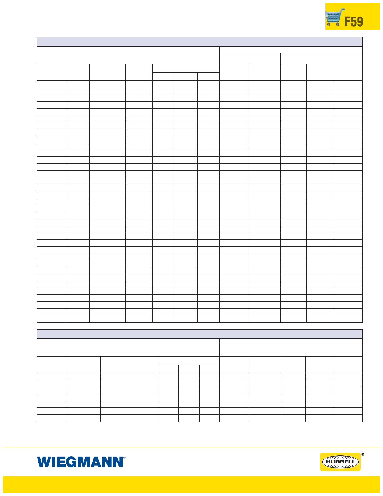
FLOOR-MOUNT • FREESTANDING • MODULAR SERIES ENCLOSURES
DISCONNECT SPACE OCCUPIED & AVAILABLE WIRING SPACE INFORMATION
F59
SCHNEIDER SQUARE D®CLASS 9422 VARIABLE DEPTH DISCONNECT SWITCHES
TYPE AMP FUSE FUSE
NUMBER RATING CLIP CLASS
TCN-30 30A No fuse — 3.80 6.97 0.56 6.75 12.75 10.75 16.75 19.75
TCF-30 30A 30A-250V H, K, R 5.53 6.97 0.56 6.75 12.75 10.75 16.75 19.75
TCF-33 30A 30A-600V H, K, R 8.15 6.97 0.56 6.75 12.75 10.75 16.75 19.75
TCF-33 30A 60A-250V H, K, R 6.15 6.97 0.56 6.75 12.75 10.75 16.75 19.75
TCF-33 30A 30A-600V J 5.53 6.97 0.56 6.75 12.75 10.75 16.75 19.75
TDN-60 60A No fuse — 3.80 6.97 0.56 6.75 12.75 10.75 16.75 19.75
TDF-60 60A 30A-600V H, K, R 8.15 6.97 0.56 6.75 12.75 10.75 16.75 19.75
TDF-60 60A 60A-250V H, K, R 6.15 6.97 0.56 6.75 12.75 10.75 16.75 19.75
TDF-63 60A 60A-600V H, K, R 8.65 6.97 0.56 6.75 12.75 10.75 16.75 19.75
TDF-63 60A 60A-600V J 5.53 6.97 0.56 6.75 12.75 10.75 16.75 19.75
TEN-10 100A No fuse — 3.80 6.97 0.56 6.62 12.62 10.62 16.62 19.62
TEF-10 100A 100A-250V H, K, R 8.25 6.97 0.56 6.62 12.62 10.62 16.62 19.62
TEF-10 100A 100A-600V H, K, R 10.25 6.97 0.56 6.62 12.62 10.62 16.62 19.62
TEF-10 100A 100A-600V J 7.05 6.97 0.56 6.62 12.62 10.62 16.62 19.62
TEF-13 100A 200A-600V J — — 0.56 6.62 12.62 10.62 16.62 19.62
TC-1 30A No fuse — 5.75 6.12 0.56 5.88 11.88 9.88 15.88 18.88
TC-2 30A 30A-250V H, K, R 5.75 6.12 0.56 5.88 11.88 9.88 15.88 18.88
TC-3 30A 30A-600V H, K, R 7.75 6.12 0.56 5.88 11.88 9.88 15.88 18.88
TC-3 30A 60A-250V H, K, R 5.88 6.12 0.56 5.88 11.88 9.88 15.88 18.88
TC-3 30A 30A-600V J 5.75 6.12 0.56 5.88 11.88 9.88 15.88 18.88
TD-1 60A No fuse — 6.38 6.75 0.56 6.75 12.75 10.75 16.75 19.75
TD-2 60A 30A-600V H, K, R 8.50 6.75 0.56 6.75 12.75 10.75 16.75 19.75
TD-2 60A 60A-250V H, K, R 6.50 6.75 0.56 6.75 12.75 10.75 16.75 19.75
TD-3 60A 60A-600V H, K, R 9.00 6.75 0.56 6.75 12.75 10.75 16.75 19.75
TD-3 60A 60A-600V J 6.38 6.75 0.56 6.75 12.75 10.75 16.75 19.75
TE-1 100A No fuse — 4.75 8.50 0.56 6.50 12.50 10.50 16.50 19.50
TE-2 100A 100A-250V H, K, R 7.50 8.50 0.56 6.50 12.50 10.50 16.50 19.50
TE-2 100A 100A-600V H, K, R 9.50 8.50 0.56 6.50 12.50 10.50 16.50 19.50
TE-2 100A 100A-600V J 6.25 8.50 0.56 6.50 12.50 10.50 16.50 19.50
TE-3 100A 200A-600V J 13.75 8.50 0.56 6.50 12.50 10.50 16.50 19.50
TF-1 200A No fuse — 5.50 11.75 0.56 5.12 11.12 9.12 15.12 18.12
TF-2 200A 200A-250V H, K, R 11.50 11.75 0.56 5.12 11.12 9.12 15.12 18.12
TF-2 200A 200A-600V H, K, R 14.00 11.75 0.56 5.12 11.12 9.12 15.12 18.12
TF-2 200A 200A-600V J 10.12 11.75 0.56 5.12 11.12 9.12 15.12 18.12
TF-3 200A 400A-600V J 14.50 11.75 0.56 5.12 11.12 9.12 15.12 18.12
SPACE OCCUPIED
FG K
†
TWO DOOR FLOOR-MOUNT
(PAGES F28-F29 & F45-F46) (PA GES F32-F49)
WIRE BEND SPACE “WB” ABOVE DISCONNECT
FREESTANDING & MODUL AR
WHEN WHEN WHEN WHEN WHEN
H=60.12 H=72.12 H=72.12 H=84.12 H=90.12
WB WB WB WB WB
SCHNEIDER SQUARE D®CLASS 9422 VARIABLE DEPTH OPERATOR CIRCUIT BREAKERS
TYPE AMP
NUMBER RATING
RG-1 75A GJL 3.53 3.87 0.56 6.69 12.69 10.69 16.69 19.69
RG-1 100A GJL 3.53 3.87 0.56 6.69 12.69 10.69 16.69 19.69
RN-1 100A FAL, FHL 5.12 5.38 0.56 6.88 12.88 10.88 16.88 19.88
RP-1 250A KAL, KHL 7.12 5.75 0.56 7.56 13.06 11.56 17.56 20.56
RR-1 400A LAL,LHL,Q4L 7.62 8.88 0.56 — 9.25 — 13.25 16.25
RT-1 800A MEL, MXL 9.12 12.00 0.56 — — — 13.25 16.25
RT-1 1000A MAL, MHL 9.12 12.00 0.56 — — — 13.25 16.25
†For Two Door Floor-Mount NEMA 12 “E” = 7.88 when “H” = 60.12
(Pages F28-F29 & F45-F46) “E” = 13.38 when “H” = 72.12
FRAME TYPE
SPACE OCCUPIED
FG K
For Heavy Duty Freestanding “E” = 11.88 when “H” = 72.12
and Modular Enclosures “E” = 17.38 when “H” = 84.12
(Pages F32 - F49) “E” = 20.38 when “H” = 90.12
†
TWO DOOR FLOOR-MOUNT
(PAGES F28-F29 & F45-F46) ( PAG E S F32-F49)
WIRE BEND SPACE “WB” ABOVE DISCONNECT
FREESTANDING & MODUL AR
WHEN WHEN WHEN WHEN WHEN
H=60.12 H=72.12 H=72.12 H=84.12 H=90.12
WB WB WB WB WB
www.hubbell-wiegmann.com
Data Subject To Change Without Notice
Page 60
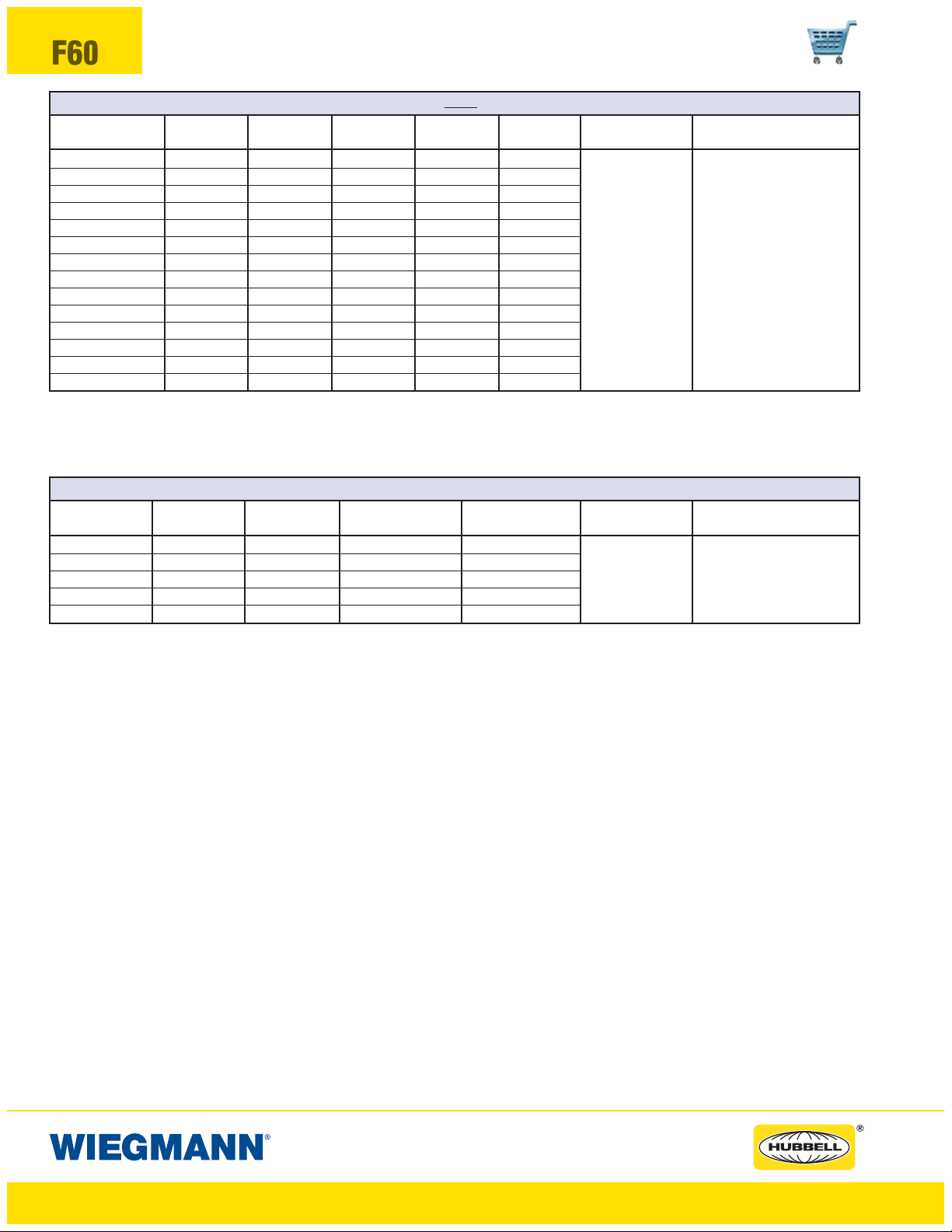
F60
FLOOR-MOUNT • FREESTANDING • MODULAR SERIES ENCLOSURES
DISCONNECT SPACE OCCUPIED & AVAILABLE WIRING SPACE INFORMATION
SCHNEIDER SQUARE D®CLASS 9422 DISCONNECT SWITCHES USED WITH CABLE MECHANISM 9422-CFT30 AND 9422-A1 HANDLE MECHANISM
TYPE AMP FUSE FUSE DISCONNECT DISCONNECT TWO DOOR
NUMBER RATING CLIP CLASS HEIGHT X WIDTH Y FLOOR-MOUNT
TCN-30C 30A No fuse — 5.90 6.20
TCF-30C 30A 30A-250V H, K, R 7.50 6.20
TCF-33C 30A 30A-600V H, K, R 10.15 6.20
TCF-33C 30A 60A-250V H, K, R 8.15 6.20
TCF-33C 30A 30A-600V J 7.50 6.20
TDN-60C 60A No fuse — 5.90 6.20 For enclosures
TDF-60C 60A 30A-600V H, K, R 10.15 6.20 that accept
TDF-60C 60A 60A-250V H, K, R 8.15 6.20 these devices,
TDF-63C 60A 60A-600V H, K, R 10.65 6.20 see pages F28-F29
TDF-63C 60A 60A-600V J 7.50 6.20 & F45-F46
TEN-10C 100A No fuse — 5.90 6.20
TEF-10C 100A 100A-250V H, K, R 10.35 6.20
TEF-10C 100A 100A-600V H, K, R 10.35 6.20
TEF-10C 100A 100A-600V J 10.35 6.20
Use switches listed above with appropriate cable mechanism and 9422-A1 handle mechanism. Cable operators are available in 3-foot, 5-foot, and 10-foot lengths.
Numbers shown (30) are for 3-foot cables.
SCHNEIDER SQUARE D®CLASS 9422 CABLE MECHANISM FOR CIRCUIT BREAKERS
CABLE TYPE CIRCUIT B CIRCUIT B CIRCUIT BREAKER CIRCUIT BREAKER TWO DOOR
SWITCH AMP RATING FRAME TYPE HEIGHT X WIDTH Y FLOOR-MOUNT
9422 CGJ30 75A GJL 4.75 3.50
9422 CGJ30 100A GJL 4.75 3.50
9422 CFA30 100A FAJ, FHL 6.00 4.50
9422 CKA30 250A KAL, KHL 8.00 4.50
9422 CLA30 400A LAL, LHL, Q4L 11.00 6.00
Use cable mechanism with appropriate circuit breaker and 9422-A1 handle mechanism. Cable operators are available in 3-foot, 5-foot, and 10-foot lengths.
Numbers shown (30) are for 3-foot cables.
For enclosures that
accept these devices,
see page F28-F29 &
F45-F46
FREESTANDING MODULAR
For enclosures
that accept these devices,
see pages F32-F49
FREESTANDING MODULAR
For enclosures that accept
these devices,
see pages F32-F49
Space Occupied by Disconnect Switch or Circuit Breaker
• Schneider Square D
•RefertoNational Electrical Code
• Choose cable mechanism length based on placement of disconnect in enclosure. See Schneider Square D®instruction Bulletin for minimum bend radius
for cable.
• Space occupied by disconnect is determined by overall height “X”, width “Y”, wire bend space “WB” and location “G” as selected from right to left.
†For Two Door Floor-Mount NEMA 12 “E” = 7.88 when “H” = 60.12
(Pages F28-F29 & F45-F46) “E” = 13.38 when “H” = 72.12
For Heavy Duty Freestanding “E” = 11.88 when “H” = 72.12
and Modular Enclosures “E” = 17.38 when “H” = 84.12
(Pages F32 - F49) “E” = 20.38 when “H” = 90.12
®
cable mechanisms allows disconnect devices to be positioned independent from the flange-mounted handle mechanism.
®
article 430-10(b) for wiring space “WB” required for line side conductors.
www.hubbell-wiegmann.com
Data Subject To Change Without Notice
Page 61

WA21ABA WA22BAP
FEATURES-SPECIFICATIONS
ENCLOSURES
NEMA 12 ADAPTER PLATES
F61
OPERATOR ADAPTER PLATES
•
Used on all Wiegmann disconnect enclosures with
universal flange cutouts
• An operator adapter plate is required to install a
disconnect in all Wiegmann enclosures with a
universal cutout on pages F28-F49.
• Operator adapters include an adapter plate and additional parts used to interlock the master door with the
disconnect operating mechanism. Panel drilling and
installation instructions are furnished with each adapter
• Each brand and type of disconnect requires a different
operator adapter. It is important to select the proper
operator adapter and enclosure for the disconnect that
you have selected
OPERATOR ADAPTER PLATES
CATALOG
NUMBER
WA21ABA Allen-Bradley 1494F and 1494D
WA21ABVA Allen-Bradley 1494V, 140U, 1494C, 194RC
WA21CHVA Eaton Cutler-Hammer C361, C371 and C371 Flex Shaft
WA21CHVA ABB Controls Varible Depth, S1, S2, T5 cable size
WA21FUFA Fuji
WA21GETDA General Electric STDA
WA21ITE Siemens ITE Max-Flex™, ABB Controls Cable S3-S5, S6, S7
WA21SDA Schneider Square D®Class 9422, (variable depth and cable mechanism)
WA21WHA Eaton Cutler-Hammer/Westinghouse
TYPE OF OPERATOR ADAPTER
™
SM
BLANK ADAPTER PLATES
• Used to cover flange cutouts in disconnect enclosures
when disconnects are not installed. This greatly increases the versatility of the disconnect enclosures enabling
themtoalsobeusedasregularType12enclosures
• Wiegmann blank adapter plates are made from heavy
gauge steel, with oil-resistant gasket to maintain the
dust-tight and oil-tight qualities of the enclosure
• All blank adapter plates are painted ANSI 61 gray
polyester powder
• All necessary mounting hardware and instructions
are included
BLANK ADAPTER PLATES
CATA L O G
NUMBER
WA21BAP
WA22BAP Blank adapter for enclosures on page F24
WA3456BAP
Blank adapter for universal cutouts on pages
F28- F49
Blank adapter for single door wall-mount enclosures
on pages F2- F13.
TYPE OF OPERATOR ADAPTER
www.hubbell-wiegmann.com
Data Subject To Change Without Notice
DATA SUBJECT TO CHANGE WITHOUT NOTICE
Page 62

NOTES
www.hubbell-wiegmann.com
Data Subject To Change Without Notice
 Loading...