

Page 1
DATA SUBJECT TO CHANGE WITHOUT NOTICE
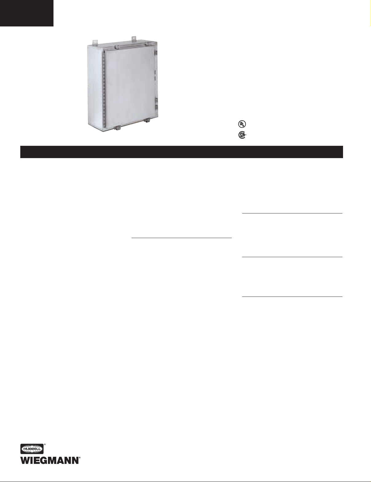
SSN4X SERIES ENCLOSURES
NEMA 4X FLANGED SINGLE DOOR DISCONNECT
F20
FEATURES-SPECIFICATIONS
Industry Standards
UL 508, Types 4, 4X, 12, & 13
CSA Certified, Types 4 & 12
NEMA/EEMAC Types 4, 4X, 12, & 13
JIC EL-1-71
UL File E64791
CSA File LL66078
Applications
Designed to house the following:
• Allen-Bradley Bulletin 1494V dis-
connect switches with flange-mounted
variable depth operating mechanisms
and Bulletin 1494V flange-mounted
variable depth operating mechanisms
for circuit breakers.
Allen-Bradley Bulletin 1494V-R1,
-R2, and -W2 operating handles
and Allen-Bradley Bulletin 1494F
disconnect devices or Bulletin 1494D
circuit breaker operators will not fit
these enclosures
• ABB Controls flange-mounted
variable depth operating mechanisms
for disconnect switches and circuit
breakers
• Cutler-Hammer/Westinghouse
Type C361 flange-mounted variable
depth operating mechanisms with
disconnect switches and Type C371
flange-mounted variable depth
operating mechanisms for circuit
breakers. Flex Shaft™ handle
operators for circuit breakers
• General Electric Type STDA flange
handles and variable depth operating
mechanisms for disconnect switches
and circuit breakers. Also Spectra
Flex™ cable operators for circuit
breakers
• I-T-E Max-Flex™ flange-mounted
variable depth operating handles for
circuit breakers.
• Square D Class 9422 disconnect
switches with flange-mounted variable
depth operating mechanisms or
cable mechanisms and Class 9422
flange-mounted variable depth
operating mechanisms or cable
mechanism for circuit breakers
These enclosures will not accept
Square D Class 9422 bracket-mounted
disconnect devices, 9422 TG1, or TG2
devices
Construction
• Bodies and doors fabricated from
14 gauge 304 stainless steel
• Continuously welded seams ground
smooth
• Rolled lip around all sides of enclosure opening excludes liquids and
contaminants
• All exterior hardware is stainless steel
• All interior and exterior parts of stainless steel enclosures are stainless
steel except for print pocket
• Stainless steel door clamps are
provided around three sides of doors
for a watertight seal, additional door
hardware is not required
• Body and door stiffeners provided
in larger enclosures for extra rigidity
• Doors removed by pulling stainless
steel continuous hinge pin
• Polyurethane poured-in-place gasket
• External mounting feet
• Collar studs for mounting optional
back panel
• Grounding provisions provided
• Bracket welded to door for attaching
disconnect interlock door catch
• Holes are provided in body for
mounting disconnect operating handle
and operating mechanism. These
enclosures are designed to operate
properly without the use of door
hardware
• Print pocket is provided
Finish
• Enclosures have a grained finish on
all external surfaces
• Optional back panels are white
polyester powder over phosphatized
surfaces
Accessories
• Back panels (reference tables)
• See pages J1-J19
• Blank Adapter Plates are on pages
F57 and J12
IMPORTANT
• Disconnect switch or circuit breakers, operating handle, and operating
mechanism are not furnished with
enclosure and must be ordered
separately from the disconnect
manufacturer
• Operator adapter plates are not
required with this enclosure
• Disconnect ordering information is
located on page F22
• Review space occupied by disconnect drawing on page F21 and
disconnect tables on pages F23-F29
to determine if the disconnect device
you are using will fit the enclosure
size you have selected
SSN4X242108
®
R
Page 2
DATA SUBJECT TO CHANGE WITHOUT NOTICE
SSN4X SERIES ENCLOSURES
NEMA 4X FLANGED SINGLE DOOR DISCONNECT
F21
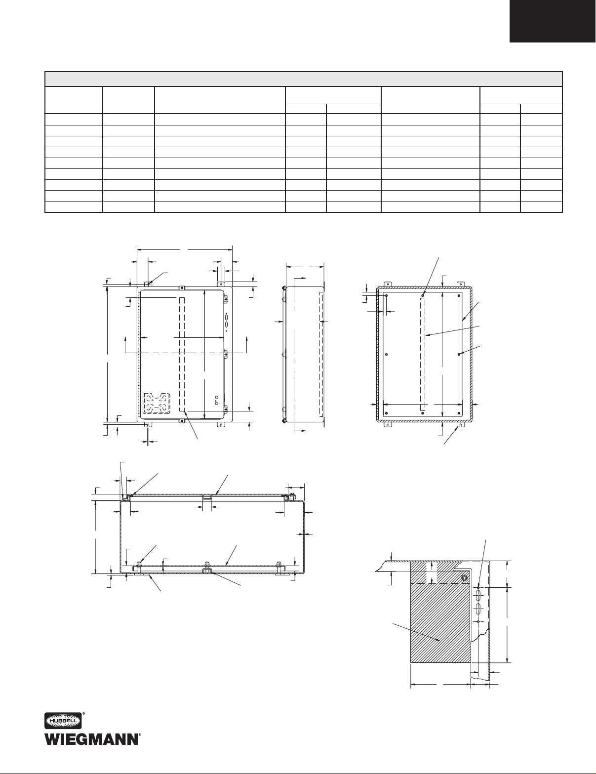
CATALOG BODY/DOOR ENCLOSURE SIZE
BACK PANEL
BACK PANEL STIFFENER
NUMBER STEEL GAUGE H X W X D
CATALOG NUMBER*
SIZE A X B
WHITE 316 S.S. DOOR BODY
SSN4X242108 14/14 24.00x21.38x8.13 (610x543x207) NP2420 NP2420SSA6 21.00x17.00 (533x432) No No
SSN4X242508 14/14 24.00x25.38x8.13 (610x645x207) NP2424 NP2424SSA6 21.00x21.00 (533x533) No No
SSN4X302508 14/14 30.00x25.38x8.13 (762x645x207) NP3024 NP3024SSA6 27.00x21.00 (686x533) No No
SSN4X362508 14/14 36.00x25.38x8.13 (914x645x207) NP3624 NP3624SSA6 33.00x21.00 (838x533) No No
SSN4X363108 14/14 36.00x31.38x8.13 (914x797x207) NP3630 NP3630SSA6 33.00x27.00 (838x686) No Yes
SSN4X423112 14/14 42.00x31.38x12.13 (1067x797x308) NP4230 NP4230SSA6 39.00x27.00 (991x686) Yes Yes
SSN4X423712 14/14 42.00x37.38x12.13 (1067x949x308) NP4236 NP4236SSA6 39.00x33.00 (991x838) Yes Yes
SSN4X483712 14/14 48.00x37.38x12.13 (1219x949x308) NP4836 NP4836SSA6 45.00x33.00 (1143x838) Yes Yes
SSN4X603712** 14/14 60.00x37.38x12.13 (1524x949x308) NP6036 NP6036SSA6 57.00x33.00 (1448x838) Yes Yes
SSN4X SERIES STAINLESS WALL-MOUNT DISCONNECTS
6 NEW PRODUCT IN 2003
*Back panels must be ordered separately.
**Enclosures are supplied with closed cell neoprene gasket (not foam-in-place).
0.63
3.00
Ø0.44
W
3.00
2.00
D
Y
OMIT TWO MIDDLE STUDS
IF W = LESS THAN 32.00"
1.50
0.63
D
0.19
0.63
0.88
1.31
H
3.00
X
1.25
0.44
CONTINUOUS
HINGE
1.09
1.25
D-0.28
W-3.13
GASKET
3/8 - 16 COLLAR
STUD
12 GA.
MOUNTING
FEET
H-1.63
DOOR STIFFENER
IF H = 42.00" OR MORE
X
3.00
DOOR
STIFFENER
1.25 TYP
PANEL
(ORDER SEPARATELY)
BODY
STIFFENER
2.50
2.75
14 GA.
0.75
SECTION X-X
Space Occupied by Disconnect
E = 8.63 when D = 8.00
E = 11.62 when D = 12.00
WB = Wiring Space
See pages F23-F29 for various brands
of disconnects for "F", "G" & "WB" dimensions.
Disconnects will occupy space on panel shown by dimension
"E", "F", & "G". Wiring space "WB" is available when disconnect
is installed in the enclosure.
Refer to National Electrical Code 1996 article 430-10(b) for
wiring space required for line side conductors to be connected
to disconnect. Verify your application to determine if wiring
space is adequate.
0.88
0.88
Y
Notes:
1. Large print pocket (8" x 10") is
provided in each enclosure.
2. Panels are made from 12 Ga. steel.
3. Panels have flanges along all sides when
either dimension exceeds 17".
4. The number of door clamps is dependent
on size of enclosure. Clamps are furnished
along three sides of door.
1.50
THIS SPACE IS OCCUPIED
BY DISCONNECT SWITCH
AND FUSE CLIP (IF USED)
OR CIRCUIT BREAKER.
PANEL
(Order
Separately)
STIFFENER
SEE TABLE
OMIT TWO MIDDLE
STUDS IF H = LESS
THAN 31.00"
A
B1.75 2.62
1.50
MOUNTING FEET
SECTION Y-Y
TOP HOLE IN
R.H. FLANGE
WB
1.59
G
2.75
E
F
Page 3

DATA SUBJECT TO CHANGE WITHOUT NOTICE
SSN4X SERIES ENCLOSURES
NEMA 4X FLANGED SINGLE DOOR DISCONNECT
F22
Allen-Bradley
When using a Bulletin 1494V disconnect
switch, order:
1. A disconnect switch with operating
mechanism (Bulletin 1494V)
2. An operating handle (Bulletin 1494V-W1)
3. A connecting rod [Bulletin 1494V-RA1
for 8.00" (203mm) deep enclosures;
Bulletin 1494V-RA2 for 12.00" (305mm)
deep enclosures]
4. A trailer fuse block kit, if required
(Bulletin 1494V)
5. A fuse clip kit, if required
6. Line and load connectors, if required
When using a Bulletin 1494V circuit
breaker operating mechanism, order:
1. A circuit breaker (C-H/Westinghouse)
2. A circuit breaker operating mechanism
(Bulletin 1494V)
3. An operating handle (Bulletin 1494V-W11)
4. A connecting rod [Bulletin 1494V-RA1
for 8.00" (203mm) deep enclosures;
Bulletin 1494V-RA2 for 12.00" (305mm)
deep enclosures]
ABB Controls
When using a disconnect switch, order:
1. A flange operated switch (fusible or
non-fusible)
2. A shaft [DSFHS-12]
3. A handle (DSFHN-HS4)
When using a circuit breaker, order:
1. A circuit breaker (ABB)
*2. An operating mechanism
*3. A shaft [FHS-12]
*4. A handle (FHN-HS4)
Cutler-Hammer/Westinghouse
When using a Type C361 disconnect switch,
order:
*1. A disconnect switch with an
operating mechanism
*2. An operating handle (C361H2 or
C361H4)
When using a Type C371 circuit breaker
operating mechanism with a C-H/
Westinghouse circuit breaker, order:
1. A circuit breaker
*2. An operating mechanism
*3. An operating handle (C371H2 or
C371H4)
When using a C-H/Westinghouse circuit
breaker with a Type 4/4X Flex Shaft™ handle
mechanism, order:
1. A circuit breaker
2. A complete Flex Shaft™ handle
mechanism
General Electric
When using a disconnect switch, order:
1. A disconnect switch (Type QMR or
QMW)
2. A fuse clip kit or no-fuse kit
3. A flange handle (STDA1X)
4. A variable depth operating mechanism
When using a circuit breaker, order:
1. A circuit breaker
2. A flange handle (STDA1X)
3. A variable depth operating mechanism
When using a circuit breaker with a Spectra
Flex™ cable operator, order:
1. A circuit breaker
2. A flange-mounted handle mechanism
3. A breaker-mounted mechanism
4. An operating cable
I-T-E Siemens
When using a disconnect switch, order:
1. A basic switch (right-hand)
2. A fuse or no-fuse kit
3. A flange-mounted handle (FHOHS4)
4. Switch operator
5. Cable, 36.00"
When using a circuit breaker, order:
1. A circuit breaker
2. Pressure wire connectors
3. A flange-mounted handle (FHOH4)
4. A circuit breaker operator mechanism
5. An operating cable (standard 36.00")
Square D
When using a Class 9422 disconnect switch,
order:
1. A disconnect switch with operating
mechanism (Class 9422)
2. A handle mechanism (Class 9422
Type A2)
When using a circuit breaker, order:
1. A circuit breaker (Square D)
2. An operating mechanism (Class 9422)
3. A handle mechanism (Class 9422
Type A2)
When using a Class 9422 Type “T”
disconnect switch with a cable mechanism,
order:
1. A disconnect switch with operating
mechanism (Class 9422, Type T)
2. A handle mechanism (Class 9422
Type A2)
3. A cable mechanism (Class 9422
CFT_O) 3-, 5-, or 10-foot
When using a circuit breaker with a cable
mechanism, order:
1. A circuit breaker (Square D)
2. A handle mechanism (Class 9422
Type A2)
3. A cable mechanism (Class 9422
CFT_O) 3-, 5-, or 10-foot
PLEASE NOTE:
1. Operator adapter plates and door hardware are not required with enclosures on page F21.
2. Various other switch accessories and circuit breaker accessories are available from disconnect
manufacturers. The above information is subject to change without notice. Please contact
Hubbell/Wiegmann or the disconnect manufacturer if there are further questions.
3. The “Space Occupied” tables (pages F23-F29) are based upon information supplied by
disconnect manufacturers. Hubbell/Wiegmann does not assume responsibility for the accuracy
of these dimensions.
* Items available from disconnect manufacturer as complete kits.
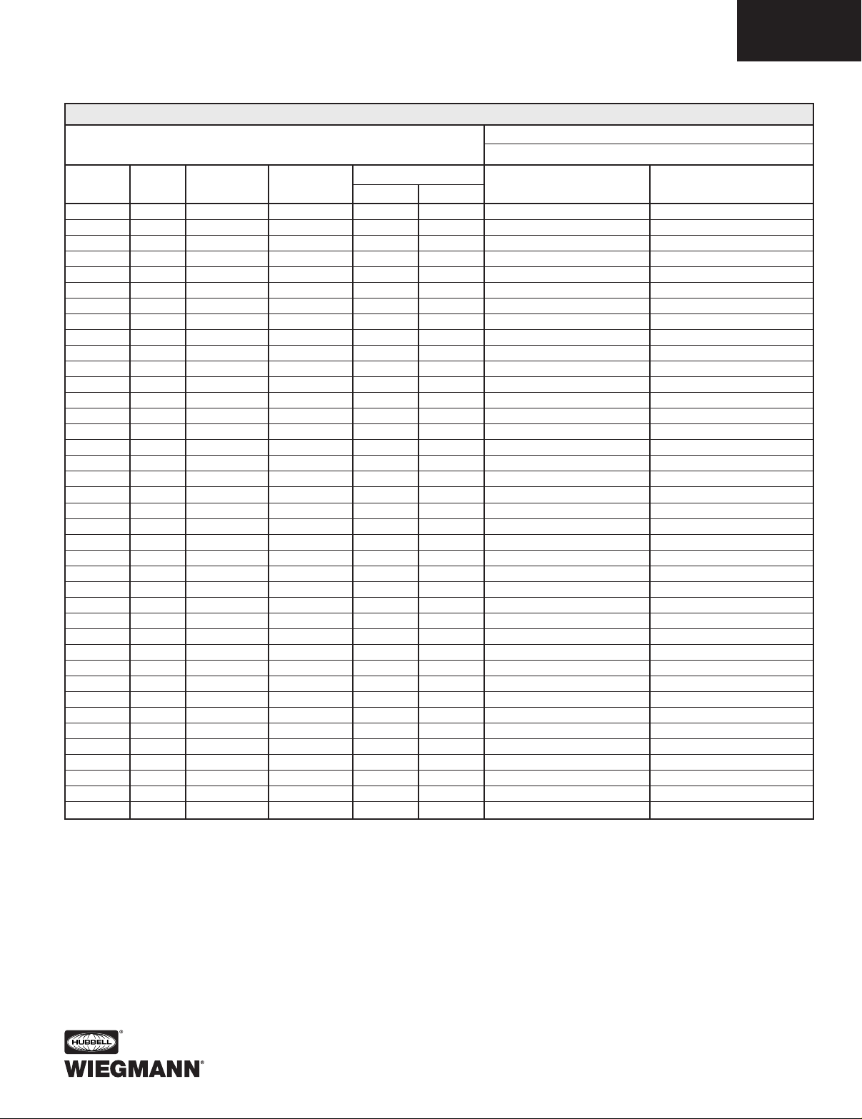
DISCONNECT ORDERING INFORMATION
When ordering wall-mounted disconnects from the various manufacturers, be sure to order all
of the necessary items. Each company has a different system, so care is required. Order the
following items from the disconnect manufacturer.
Use a Type 4 or 4X (stainless steel) disconnect operating handle on the enclosure flange to
provide corrosion resistance and maintain enclosure rating.
Page 4

DATA SUBJECT TO CHANGE WITHOUT NOTICE
SSN4X SERIES ENCLOSURES
DISCONNECT SPACE OCCUPIED & AVAILABLE WIRING SPACE INFORMATION
F23
DS30 30A No fuse — 3.88 6.62 6.75 9.75
DS30 30A 30A-250V H, K, R 5.25 6.62 6.75 9.75
DS30 30A 30A-600V H, K, R 8.00 6.62 6.75 9.75
DS30 30A 30A-600V J 5.25 6.62 6.75 9.75
DS30 30A 60A-250V H, K 6.00 6.62 6.75 9.75
DS30 30A 60A-600V H, K 8.50 6.62 6.75 9.75
DS30 30A 60A-600V J 5.38 6.62 6.75 9.75
DS60 60A No fuse — 3.88 6.62 6.62 9.62
DS60 60A 60A-250V H, K, R 6.00 6.62 6.62 9.62
DS60 60A 60A-600V H, K, R 8.50 6.62 6.62 9.62
DS60 60A 60A-600V J 5.38 6.62 6.62 9.62
DS60 60A 30A-600V H, K, R 8.00 6.62 6.62 9.62
DS60 60A 100A-250V H, K 8.50 6.62 6.62 9.62
DS60 60A 100A-600V H, K 10.50 6.62 6.62 9.62
DS60 60A 100A-600V J 7.25 6.62 6.62 9.62
DS100** 100A No fuse — 3.88 6.62 6.44 9.62
DS100** 100A 100A-250V H, K, R 8.12 6.62 6.44 9.62
DS100** 100A 100A-600V H, K, R 10.12 6.62 6.44 9.62
DS100** 100A 100A-600V J 6.88 6.62 6.44 9.62
DS100** 100A 60A-600V H, K, R 10.12 6.62 6.44 9.62
DS100** 100A 60A-600V J 8.88 6.62 6.44 9.62
DS200** 200A No fuse — 4.75 7.88 — 8.12
DS200** 200A 200A-250V H, K, R 10.88 7.88 — 8.12
DS200** 200A 200A-600V H, K, R 13.38 7.88 — 8.12
DS200** 200A 200A-600V J 9.50 7.88 — 8.12
DS200** 200A 100A-600V H, K, R 12.00 7.88 — 8.12
DS200** 200A 100A-600V J 8.75 7.88 — 8.12
Westinghouse
M40 15A-150A
Circuit Breakers
— 5.00 4.50 8.12 11.12
EHD, FD, FDB,
FDC, HFD, HMCP
Westinghouse
M50 70A-250A
Circuit Breakers
— 9.75 4.75 — 10.62
JD, JDB, JDC,
HJD, HMCP
Westinghouse
M60 100A-400A
Circuit Breakers
— 9.69 6.12 — 10.50
KD, KDB, KDC,
HKD, HMCP
TYPE AMP FUSE FUSE
SPACE OCCUPIED
WHEN WHEN
NUMBER RATING CLIP CLASS
FG*
D=8.00 D=12.00
WB WB
ALLEN-BRADLEY BULLETIN 1494V DISCONNECTS
WIRE BEND SPACE “WB” ABOVE DISCONNECT
SSN4X WALL-MOUNTS (PAGES F20-F22)
*Does not include space for optional auxiliary switch
**Series B
Page 5

DATA SUBJECT TO CHANGE WITHOUT NOTICE
SSN4X SERIES ENCLOSURES
DISCONNECT SPACE OCCUPIED & AVAILABLE WIRING SPACE INFORMATION
F24
OETL-NF30-F 40A No fuse — 4.45 3.78 10.28 13.28
OETL-NF60-F 80A No fuse — 4.86 3.78 10.09 13.09
OETL-NF100-F 100A No fuse — 4.86 4.78 9.53 12.53
OETL-NF175-F 175A No fuse — 7.30 6.49 7.28 10.28
OETL-NF200-F 200A No fuse — 7.36 7.28 7.28 10.28
OESA-F30J6-F 30A 30A-600V J 4.28 6.58 8.61 11.61
OESA-F60J6-F 60A 60A-600V J 4.28 6.26 8.61 11.61
OESA-F100J6-F 100A 100A-600V J 6.54 7.65 8.17 11.17
SWITCH AMP FUSE FUSE
SPACE OCCUPIED
WHEN WHEN
NUMBER RATING CLIP CLASS
FG
D=8.00 D=12.00
WB WB
ABB CONTROLS DISCONNECT SWITCHES WITH FLANGE-MOUNTED OPERATORS
FHD-M 150A D 6.92 3.94 9.17 12.17
FHF-M 150A-225A E/Q 5.98 4.23 7.72 10.72
FHF-M 225A F 7.44 4.23 7.72 10.72
FHJ-M 400A J 9.71 5.62 — 8.77
FHM-M 600A L 8.28 11.26 — 8.28
FHM-M 800A M 10.11 11.26 — 7.87
AMP FRAME
SPACE OCCUPIED
WHEN WHEN
MECHANISM
RATING TYPE
FG
D=8.00 D=12.00
WB WB
ABB CONTROLS CIRCUIT BREAKERS WITH FLANGE-MOUNTED OPERATORS
C361 NC 30A No fuse — 5.75 7.43 7.31 10.31
C361 SC21 30A 30A-250V H, K, R 8.38 7.43 7.31 10.31
C361 SC61 30A 60A-250V H, K, R 8.38 7.43 7.31 10.31
C361 SC61 30A 30A-600V H, J, K, R 8.38 7.43 7.31 10.31
C361 ND 60A No fuse — 5.75 7.43 7.31 10.31
C361 SD22 60A 60A-250V H, K, R 8.38 7.43 7.31 10.31
C361 SD22 60A 30A-600V J 8.38 7.43 7.31 10.31
C361 SD62 60A 60A-600V H, K, R 8.38 7.43 7.31 10.31
C361 SD62 60A 60A-600V J 8.38 7.43 7.31 10.31
C361 NE 100A No fuse — 5.56 8.95 7.47 9.91
C361 SE263 100A 100A-250V H, K, R 10.31 8.95 7.47 9.91
C361 SE263 100A 100A-600V H, K, R 10.31 8.95 7.47 9.91
C361 SE263 100A 100A-600V J 10.31 8.95 7.47 9.91
C361 NF* 200A No fuse — 13.06 10.00 4.94 7.94
C361 SF264* 200A 200A-250V H, K, R 13.06 10.00 4.94 7.94
C361 SF264* 200A 200A-600V H, J, K, R 13.06 10.00 4.94 7.94
SWITCH TYPE AMP FUSE FUSE
SPACE OCCUPIED
WHEN WHEN
NUMBER NUMBER RATING CLIP CLASS
FG
D=8.00 D=12.00
WB WB
CUTLER-HAMMER C361 CIRCUIT DISCONNECT SWITCHES
*200 amp switch should be installed in an enclosure with an "H" dimension of 30.00 inches (762mm) or more.
WIRE BEND SPACE “WB” ABOVE DISCONNECT
SSN4X WALL-MOUNTS (PAGES F20-F22)
WIRE BEND SPACE “WB” ABOVE DISCONNECT
SSN4X WALL-MOUNTS (PAGES F20-F22)
WIRE BEND SPACE “WB” ABOVE DISCONNECT
SSN4X WALL-MOUNTS (PAGES F20-F22)
Page 6

DATA SUBJECT TO CHANGE WITHOUT NOTICE
SSN4X SERIES ENCLOSURES
DISCONNECT SPACE OCCUPIED & AVAILABLE WIRING SPACE INFORMATION
F25
C371E 225A F Frame: EHD, FDB, FD, HFD, FDC 6.00 5.50 8.44 11.44
C371E 150A F Frame: HMCP 6.00 5.50 8.44 11.44
C371F 250A J Frame: JDB, JD, HJD, JDC 8.94 8.00 — 11.25
C371F 250A J Frame: HMCP 10.94 8.00 — 11.25
C371F 400A K Frame: DK, KDB, KD, HKD 9.75 8.00 — 10.75
C371F 400A K Frame: HMCP 9.75 8.00 — 10.75
C371G 600A L Frame: LD, HLD, LDC 8.44 11.88 — 9.18
C371G 600A L Frame: HMCP 8.44 11.88 — 9.18
AMP
SPACE OCCUPIED
WHEN WHEN
MECHANISM
RATING
FRAME TYPE
FG
D=8.00 D=12.00
WB WB
CUTLER-HAMMER C371 CIRCUIT BREAKER OPERATORS FOR C-H/WESTINGHOUSE CIRCUIT BREAKERS
WIRE BEND SPACE “WB” ABOVE DISCONNECT
SSN4X WALL-MOUNTS (PAGES F20-F22)
COMPLETE OPERATOR AMP FRAME BREAKER BREAKER
MECHANISM RATING TYPE HEIGHT WIDTH
F1S03 225A F Frame: EHD, FDB, FD, HFD, FDC 6.00 4.12
F1S03 150A F Frame: HMCP 6.00 4.12
F2S03 250A J Frame: JDB, JD, HJD, JDC 10.00 4.12
F2S03 250A J Frame: HMCP 10.00 4.12
F3S03 400A K Frame: DK, KDB, KD, HKD 10.12 5.50
F3S03 400A K Frame: HMCP 12.45 5.50
F4S04 600A L Frame: LD, HLD, LDC 10.75 8.25
F4S04 600A L Frame: HMCP 12.50 8.25
F7S04 800A M Frame: MD, MDS 16.00 8.25
F5S04 1200A N Frame: ND, HND, NDC 16.00 8.25
F6S04 2500A R Frame: RD, CRD, RDC 16.00 15.50
CUTLER-HAMMER FLEX SHAFT™OPERATOR MECHANISMS FOR C-H/WESTINGHOUSE CIRCUIT BREAKERS
• Catalog numbers for complete mechanisms include a flange-mounted handle, flexible shaft and circuit breaker mechanism.
• The last digit of the catalog number denotes the length of shaft (F1S03 = 3-foot shaft). The F, J, K frame Flex Shafts™
are available in 3-foot to 10-foot lengths. The L, N, R frame Flex Shafts are available in 4-foot to 6-foot lengths.
Space Occupied by Disconnect
• The Flex Shaft™ system allows the circuit breaker to be positioned independent from the flange-mounted handle mechanism.
• Refer to National Electrical Code
®
1996 article 430-10(b) for wiring space "WB" required for line side conductors.
• Choose the length of shaft based on placement of the circuit breaker in the enclosure ensuring a 4-inch min. bending
radius for the Flex Shaft™.
• Space occupied by circuit breaker is determined by overall height "X", width "Y", wire bend space "WB" and location "G"
as selected from right to left.
Page 7

DATA SUBJECT TO CHANGE WITHOUT NOTICE
SSN4X SERIES ENCLOSURES
DISCONNECT SPACE OCCUPIED & AVAILABLE WIRING SPACE INFORMATION
F26
TDOM1A 30A No fuse — 7.75* 5.25 9.12 12.12
TDOM1A 30A 30A-250V H, R 7.75* 5.25 9.12 12.12
TDOM1B 30A 30A-600V H, R 12.38* 5.25 9.12 12.12
TDOM1B 30A 60A-250V H, R 12.38* 5.25 9.12 12.12
TDOM1B 30A 60A-600V H, R 12.38* 5.25 9.12 12.12
TDOM1A 60A No fuse — 7.75* 5.25 9.12 12.12
TDOM1B 60A 60A-250V H, R 12.38* 5.25 9.12 12.12
TDOM1B 60A 60A-600V H, R 12.38* 5.25 9.12 12.12
TDOM1B 60A 100A-250V H, R 12.38* 5.25 9.12 12.12
TDOM1B 60A 100A-600V H, R 12.38* 5.25 9.12 12.12
TDOM1A 100A No fuse — 7.75* 5.25 9.12 12.12
TDOM1B 100A 100A-250V H, R 12.38* 5.25 9.12 12.12
TDOM1B 100A 100A-600V H, R 12.38* 5.25 9.12 12.12
TDOM1B 100A 200A-250V H, R 12.38* 5.25 9.12 12.12
TDOM1B 100A 200A-600V H, R 12.38* 5.25 9.12 12.12
TDOM2 200A No fuse — 7.00 9.12 6.50 9.50
TDOM2 200A 200A-250V H, R 15.38 9.12 6.50 9.50
TDOM2 200A 200A-600V H, R 15.38 9.12 6.50 9.50
AMP FUSE FUSE
SPACE OCCUPIED
WHEN WHEN
MECHANISM
RATING CLIP CLASS
FG
D=8.00 D=12.00
WB WB
GENERAL ELECTRIC TYPE STDA OPERATORS FOR DISCONNECTS
*Dimension applies to 8.00-inch (203mm) deep enclosures and is .88 less in deeper enclosures.
SDOM1A 150A TEB, TED, THED 7.75* 5.25 9.06 12.06
SDOM1A 150A TEC 7.75* 5.25 9.06 12.06
TDOM1B 150A TB1 12.38* 5.25 9.06 12.06
TDOM1B 150A TEC, TECL 12.38* 5.25 9.06 12.06
TDOM1C 150A TEL 7.75* 5.25 9.06 12.06
TDOM1D 150A THLC1 7.75* 5.25 6.62 9.62
TDOM3 225A TFJ 10.38 5.75 7.62 10.62
TDOM3 225A TFK, THFK, TFL 10.38 5.75 7.62 10.62
TDOM4 400A TJJ, TJK4, THJK4, TJL4V 8.25 9.38 6.69 9.69
TDOM4 600A TJK6, THJK6, TJ4V, TJL4V 9.38 — 6.69 9.69
TDOM5 400A TB4, TJH6S 14.25 9.38 6.69 9.69
TDOM6 225A TLB2, THLC2 11.75 9.38 6.12 9.12
TDOM6 400A TLB4, THLC4 11.75 9.38 4.75 7.75
SDOM1A 150A SPECTRA SE150 7.75* 5.25 9.06 12.06
SDOM3 250A SPECTRA SF250 10.38 5.75 7.06 10.06
SDOM4 600A SPECTRA SG600 10.00 7.00 — 7.93
AMP
FRAME TYPE
SPACE OCCUPIED
WHEN WHEN
MECHANISM
RATING
FG
D=8.00 D=12.00
WB WB
GENERAL ELECTRIC TYPE STDA OPERATORS FOR CIRCUIT BREAKERS
*Dimension applies to 8.00-inch (203mm) deep enclosures and is .88 less in deeper enclosures.
WIRE BEND SPACE “WB” ABOVE DISCONNECT
SSN4X WALL-MOUNTS (PAGES F20-F22)
WIRE BEND SPACE “WB” ABOVE DISCONNECT
SSN4X WALL-MOUNTS (PAGES F20-F22)
Page 8

DATA SUBJECT TO CHANGE WITHOUT NOTICE
SSN4X SERIES ENCLOSURES
DISCONNECT SPACE OCCUPIED & AVAILABLE WIRING SPACE INFORMATION
F27
FRAME MAXIMUM CIRCUIT BREAKER CIRCUIT BREAKER
SSN4X WALL-MOUNTS
SIZE AMP RATING HEIGHT X WIDTH Y
E150 150A 6.31 4.12
SE150 150A 6.31 4.12
SF250 250A 10.12 4.12
SG600 600A 10.09 5.50
SK1200 1200A 15.50 8.25
GENERAL ELECTRIC CIRCUIT BREAKERS WITH SPECTRA-FLEX™CABLE OPERATORS
For enclosures that accept
these devices, see page F20-F22.
FRAME BREAKER FLANGE-MOUNTING OPERATING
SIZE MECHANISM HANDLE** CABLE*
E150 SCOM1A SCH1 SC3L
SE150/SF250 SCOM1EF SCH1 SC3L
SG600 SCOM1G SCH1 SC3L
SK1200 SCOM1K SCH2K SC3H
* Operating cables are available in 3-foot to 10-foot lengths. (The number 3 in the catalog number denotes
3-foot cable.)
** Add “X” for NEMA 4 or 4X flange-mounted handle.
Space Occupied by Circuit Breaker
• The General Electric Spectra-Flex™ system allows the circuit breaker to be positioned independent from
the flange-mounted handle mechanism.
• Refer to National Electrical Code
®
1996 article 430-10(b) for wiring space "WB" required for line side conductors.
• Choose the operating cable length based on placement of the circuit breaker in the enclosure ensuring a 3-inch
minimum bending radius for the cable.
• Space occupied by circuit breaker is determined by overall circuit breaker size ("X" height and "Y" width,
plus "WB" wire bend space and location "G" as selected from right to left.
SWITCH
AMP FUSE FUSE DISCONNECT DISCONNECT
SSN4X WALL-MOUNTS
RATING CLIP CLASS HEIGHT X WIDTH Y
MCS603R 30A No fuse — 5.52 6.13
MCS603R 30A 30A-250V H, K, R 8.11 6.13
MCS603R 30A 30A-600V H, K, R 10.11 6.13
MCS603R 30A 30A-600V J 8.48 6.13
MCS606R 60A No fuse — 5.52 6.13
MCS606R 60A 60A-250V H, K, R 7.86 6.13
MCS606R 60A 60A-600V H, K, R 10.38 6.13
MCS606R 60A 60A-600V J 8.36 6.13
MCS610R 100A No fuse — 7.59 7.38
MCS610R 100A 100A-250V H, K, R 11.85 7.38
MCS610R 100A 100A-600V H, K, R 13.85 7.38
MCS610R 100A 100A-600V J 10.60 7.38
MCS620R 200A No fuse — 9.02 9.17
MCS620R 200A 200A-250V H, K, R 14.70 9.17
MCS620R 200A 200A-600V H, K, R 17.20 9.17
MCS620R 200A 200A-600V J 13.32 9.17
I-T-E DISCONNECT SWITCHES FOR MAX-FLEX™OPERATORS
For enclosures that accept
these devices, see page F20-F22.
Page 9

DATA SUBJECT TO CHANGE WITHOUT NOTICE
SSN4X SERIES ENCLOSURES
DISCONNECT SPACE OCCUPIED & AVAILABLE WIRING SPACE INFORMATION
F28
FEATURES-SPECIFICATIONS
AMP FUSE FUSE DISCONNECT DISCONNECT
SSN4X WALL-MOUNTS SWITCH
RATING CLIP CLASS HEIGHT X WIDTH Y
TCN-30 30A No fuse — 5.90 6.20
TCF-30 30A 30A-250V H, K, R 7.50 6.20
TCF-33 30A 30A-600V H, K, R 10.15 6.20
TCF-33 30A 60A-250V H, K, R 8.15 6.20
TCF-33 30A 30A-600V J 7.50 6.20
TDN-60 60A No fuse — 5.90 6.20
TDF-60 60A 30A-600V H, K, R 10.15 6.20
TDF-60 60A 60A-250V H, K, R 8.15 6.20
TDF-63 60A 60A-600V H, K, R 10.56 6.20
TDF-63 60A 60A-600V J 7.50 6.20
TEN-10 100A No fuse — 5.90 6.20
TEF-10 100A 100A-250V H, K, R 10.35 6.20
TEF-10 100A 100A-600V H, K, R 12.35 6.20
TEF-10 100A 100A-600V J 10.35 6.20
SQUARE D CLASS 9422 DISCONNECT SWITCHES USED WITH CABLE MECHANISM 9422-CFT30 AND 9422A-1 HANDLE MECHANISM
CABLE TYPE CIRCUIT BREAKER CIRCUIT BREAKER
SSN4X WALL-MOUNTS
SWITCH
AMP RATING FRAME TYPE
HEIGHT X WIDTH Y
9422 CGJ30 75A GJL 4.75 3.50
9422 CEJ30 100A GJL 4.75 3.50
9422 CFA30 100A FAL, FHL 6.00 4.50
9422 CKA30 250A FAL, KHL 8.00 4.50
9422 CLA30 400A LAL, LHL, Q4L 11.00 6.00
SQUARE D CLASS 9422 CABLE MECHANISM FOR CIRCUIT BREAKERS
Use cable mechanism with appropriate circuit breaker and 9422-A1 handle mechanism. Cable operators are available in 3-foot, 5-foot, and 10-foot lengths.
Numbers shown (30) are for 3-foot cables.
Space Occupied by Disconnect Switch or Circuit Breaker
• Square D cable mechanisms allows disconnect devices to be positioned independent from the flange-mounted handle mechanism.
• Refer to National Electrical Code®1996 article 430-10(b) for wiring space "WB" required for line side conductors.
• Choose cable mechanism length based on placement of disconnect in enclosure. See Square D Instruction Bulletin for minimum bend radius for cable.
• Space occupied by disconnect is determined by overall height "X", width "Y", wire bend space "WB" and location "G" as selected from right to left.
For enclosures that accept
these devices, see page F20-F22.
For enclosures that accept
these devices, see page F20-F22.
The last 3 digits of operator mechanism number indicate cable length in inches. 48-inch cables are available for ED, FD, JD/LD operators, and 60-inch cables for
MD/ND, PD/RD operators. The Type 4 and Type 4X applications order handle, cable and circuit breaker operator separately.
Space Occupied by Disconnect
• The I-T-E Max-Flex™ cable system allows the disconnect to be positioned independent from the flange-mounted handle mechanism.
• Refer to National Electrical Code
®
1996 article 430-10(b) for wiring space "WB" required for line side conductors.
• Refer to Siemens I-T-E installation instructions for limits on disconnect location when using 36-inch or 48-inch Max-Flex™ cables.
• Space occupied by disconnect is determined by overall height "X", width "Y", wire bend space "WB" and location "G" as selected from right to left.
COMPLETE OPERATOR CIRCUIT BREAKER MAXIMUM CIRCUIT BREAKER CIRCUIT BREAKER
CIRCUIT BREAKER TYPE
MECHANISM FRAME AMP RATING HEIGHT X WIDTH Y
FHOE036 ED 125A 6.34 3.00 ED2, ED4, ED6, HED4, HED6
FHOE036 CED 125A 9.58 3.00 CED6
FHOF036 FD 250A 9.50 4.50 FXD6-A, FD6-A, HFD6, FXD6-ETJ, HHFD6, HHFXD6
FHOJ036 CFD 250A 14.25 4.50 CFD6, CFD6-ETI
FHOJ036 JD 400A 11.00 7.50 JXD2, JXD6, JD6, HJD6, HHJD6, HHJXD6, JXD6-ETI
FHOJ036 CJD 400A 17.86 7.50 CJD6, CJD6-ETI
FHOJ036 LD 600A 11.00 7.50 LXD6, LD6, HLD6, HHLD6, HHLDX6, LXD6-ETI
FHOJ036 CLD 600A 17.86 7.50 CLD6, CLD6-ETI
FHOLM036 LMD 800A 16.00 9.00 LMD6, LMXD6, HLMD6, HLMXD6, LMXD6-ETI
I-T-E CIRCUIT BREAKERS WITH MAX-FLEX™OPERATORS
Page 10
DATA SUBJECT TO CHANGE WITHOUT NOTICE
SSN4X SERIES ENCLOSURES
DISCONNECT SPACE OCCUPIED & AVAILABLE WIRING SPACE INFORMATION
F29
TCN-30 30A No fuse — 3.80 6.84 7.56 10.56
TCF-30 30A 30A-250V H, K, R 5.53 6.84 7.56 10.56
TCF-33 30A 30A-600V H, K, R 8.15 6.84 7.56 10.56
TCF-33 30A 60A-250V H, K, R 6.15 6.84 7.56 10.56
TCF-33 30A 30A-600V J 5.53 6.84 7.56 10.56
TDN-60 60A No fuse — 3.80 6.84 7.56 10.56
TDF-60 60A 30A-600V H, K, R 8.15 6.84 7.56 10.56
TDF-60 60A 60A-250V H, K, R 6.15 6.84 7.56 10.56
TDF-63 60A 60A-600V H, K, R 8.65 6.84 7.56 10.56
TDF-63 60A 60A-600V J 5.53 6.84 7.56 10.56
TEN-10 100A No fuse — 3.80 6.84 7.44 10.44
TEF-10 100A 100A-250V H, K, R 8.25 6.84 7.44 10.44
TEF-10 100A 100A-600V H, K, R 10.25 6.84 7.44 10.44
TEF-10 100A 100A-600V J 7.05 6.84 7.44 10.44
TC-1 30A No fuse — 5.75 6.00 6.62 9.62
TC-2 30A 30A-250V H, K, R 5.75 6.00 6.62 9.62
TC-3 30A 30A-600V H, K, R 7.75 6.00 6.62 9.62
TC-3 30A 60A-250V H, K, R 5.88 6.00 6.62 9.62
TC-3 30A 30A-600V J 5.75 6.00 6.62 9.62
TD-1 60A No fuse — 6.38 6.62 7.50 10.50
TD-2 60A 30A-600V H, K, R 8.50 6.62 7.50 10.50
TD-2 60A 60A-250V H, K, R 6.50 6.62 7.50 10.50
TD-3 60A 60A-600V H, K, R 9.00 6.62 7.50 10.50
TD-3 60A 60A-600V J 6.38 6.62 7.50 10.50
TE-1 100A No fuse — 4.75 8.38 — 10.25
TE-2 100A 100A-250V H, K, R 7.50 8.38 — 10.25
TE-2 100A 100A-600V H, K, R 9.50 8.38 — 10.25
TE-2 100A 100A-600V J 6.25 8.38 — 10.25
TE-3 100A 200A-600V J 13.75 8.38 — 10.25
TF-1 200A No fuse — 5.50 11.62 — 8.88
TF-2 200A 200A-250V H, K, R 11.50 11.62 — 8.88
TF-2 200A 200A-600V H, K, R 14.00 11.62 — 8.88
TF-2 200A 200A-600V J 10.12 11.62 — 8.88
TF-3 200A 400A-600V J 14.50 11.62 — 8.88
RG-1 75A GJL Circuit breaker 3.53 3.74 7.47 10.47
RG-1 100A GJL Circuit breaker 3.53 3.74 7.47 10.47
RN-1 100A FAL, FHL Circuit breaker 5.12 5.25 7.62 10.62
RP-1 250A KAL, KHL Circuit breaker 7.12 5.62 8.38 11.38
RR-1 400A LAL,LHL,Q4L Circuit breaker 7.62 8.75 — 7.00
TYPE AMP FUSE FUSE
SPACE OCCUPIED
WHEN WHEN
NUMBER RATING CLIP CLASS
FG
D=8.00 D=12.00
WB WB
SQUARE D CLASS 9422 DISCONNECTS
WIRE BEND SPACE “WB” ABOVE DISCONNECT
SSN4X WALL-MOUNTS (PAGES F20-F22)
Page 11

NP SERIES BACK PANELS
ACCESSORY PANELS FOR NEMA 1, 3R, 12, 4 & 4X WALL-MOUNTS
I4
FEATURES-SPECIFICATIONS
Description
• Steel and stainless panels are
12 gauge
• Aluminum panels are 5052-H32
aluminum alloy, .080-inch thick
• Panel with any side over 17.00"
has 3/4" flange on all sides
• Steel panels are painted white
polyester powder
• Panels fit the following enclosures:
– NEMA 1, Large (NIC)
– NEMA 3R, Hinge Cover (RHC, Large)
– NEMA 4, 412, & 4X
Single Door (N12, N4, N412, SSN4)
– NEMA 12
2-Door Wall-Mount, (WAWF),
Single Door
Right Flange Disconnect
(SDN12, ABN12)
Large JIC (B-CH, Large)
Single door N12
CATALOG NUMBER
PAINTED STEEL 316 STAINLESS PANEL SIZE A X B
(WHITE) STEEL
ALUMINUM
NP1212 — — 9.00X9.00 (229X229)
NP1224 — — 9.00X21.00 (229X533)
NP1612 NP1612SSA ALNP1612 13.00X9.00 (330X229)
NP1616 NP1616SSA ALNP1616 13.00X13.00 (330X330)
NP1620 — — 17.00X13.00 (432X330)
NP2012 — — 17.00X9.00 (432X229)
NP2016 NP2016SSA ALNP2016 17.00X13.00 (432X330)
NP2024 — 21.00X17.00 (533X432)
NP2020 NP2020SSA ALNP2020 17.00X17.00 (432X432)
NP2412 — — 21.00X9.00 (533X229)
NP2416 NP2416SSA — 21.00X13.00 (533X330)
NP2420 NP2420SSA ALNP2420 21.00X17.00 (533X432)
NP2424 NP2424SSA ALNP2424 21.00X21.00 (533X533)
NP2430 — — 27.00X21.00 (686X533)
NP3016 — — 27.00X13.00 (686X330)
NP3020 NP3020SSA — 27.00X17.00 (686X432)
NP3024 NP3024SSA ALNP3024 27.00X21.00 (686X533)
NP3030 NP3030SSA — 27.00X27.00 (686X686)
NP3036 — — 33.00X27.00 (838X686)
NP3042 — — 39.00X27.00 (991X686)
NP3624 NP3624SSA ALNP3624 33.00X21.00 (838X533)
NP3630 NP3630SSA ALNP3630 33.00X27.00 (838X686)
NP3636 NP3636SSA — 33.00X33.00 (838X838)
NP3642 — — 39.00X33.00 (991X838)
NP4024 — — 37.00X21.00 (940X533)
NP4224 — — 39.00X21.00 (991X533)
NP4230 NP4230SSA — 39.00X27.00 (991X686)
NP4236 NP4236SSA — 39.00X33.00 (991X838)
NP4824 — — 45.00X21.00 (1143X533)
NP4830 — — 45.00X27.00 (1143X686)
NP4836 NP4836SSA ALNP4836 45.00X33.00 (1143X838)
NP6030 — — 57.00X27.00 (1448X686)
NP6036 NP6036SSA ALNP6036 57.00X33.00 (1448X838)
NP7230 — — 69.00X27.00 (1753X686)
NP7236 — — 69.00X33.00 (1753X838)
BACK PANELS FOR NEMA 1, 3R, 12, 4 & 4X WALL-MOUNT ENCLOSURES
B
A
Ø .563 TYP.
.875 TYP.
.875 TYP.
IF "A" IS LESS THAN 31"
OMIT MIDDLE HOLES
IF "B" IS LESS THAN 31"
OMIT MIDDLE HOLES
(SEE TABLE)
SIDE FLANGES
.75
TOP VIEW
SIDE VIEW
FRONT VIEW
2.0
2.0
Ø .312 TYP. (2PL)
GROUND HOLE
DATA SUBJECT TO CHANGE WITHOUT NOTICE
NP1212
 Loading...