

Page 1
DATA SUBJECT TO CHANGE WITHOUT NOTICE
ENVIRONMENTAL CONTROL
TECHNICAL DATA
L14
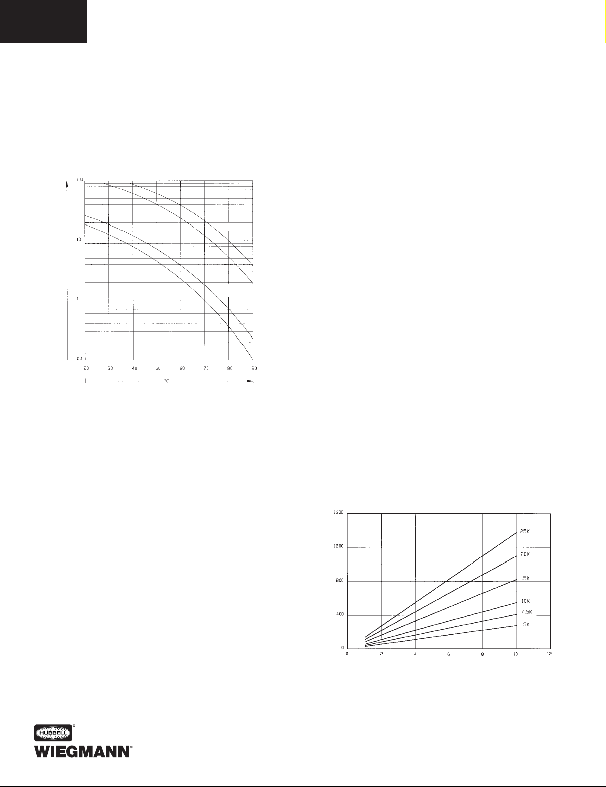
Ever since components have been made to control electrotechnical tasks, heat loss has been a subject to take into
consideration. Sometimes more—sometimes less.
Major problems with heat caused excessive dust accumulation in switchgear equipment because the doors were left
open during the summer to allow the equipment to cool
down. This can result in fluctuations in temperature. These
lead to stress situations that can considerably reduce the
service life of electronic components (see chart).
THREE BASIC COOLING METHODS
When selecting a cooling method there are three types
to consider:
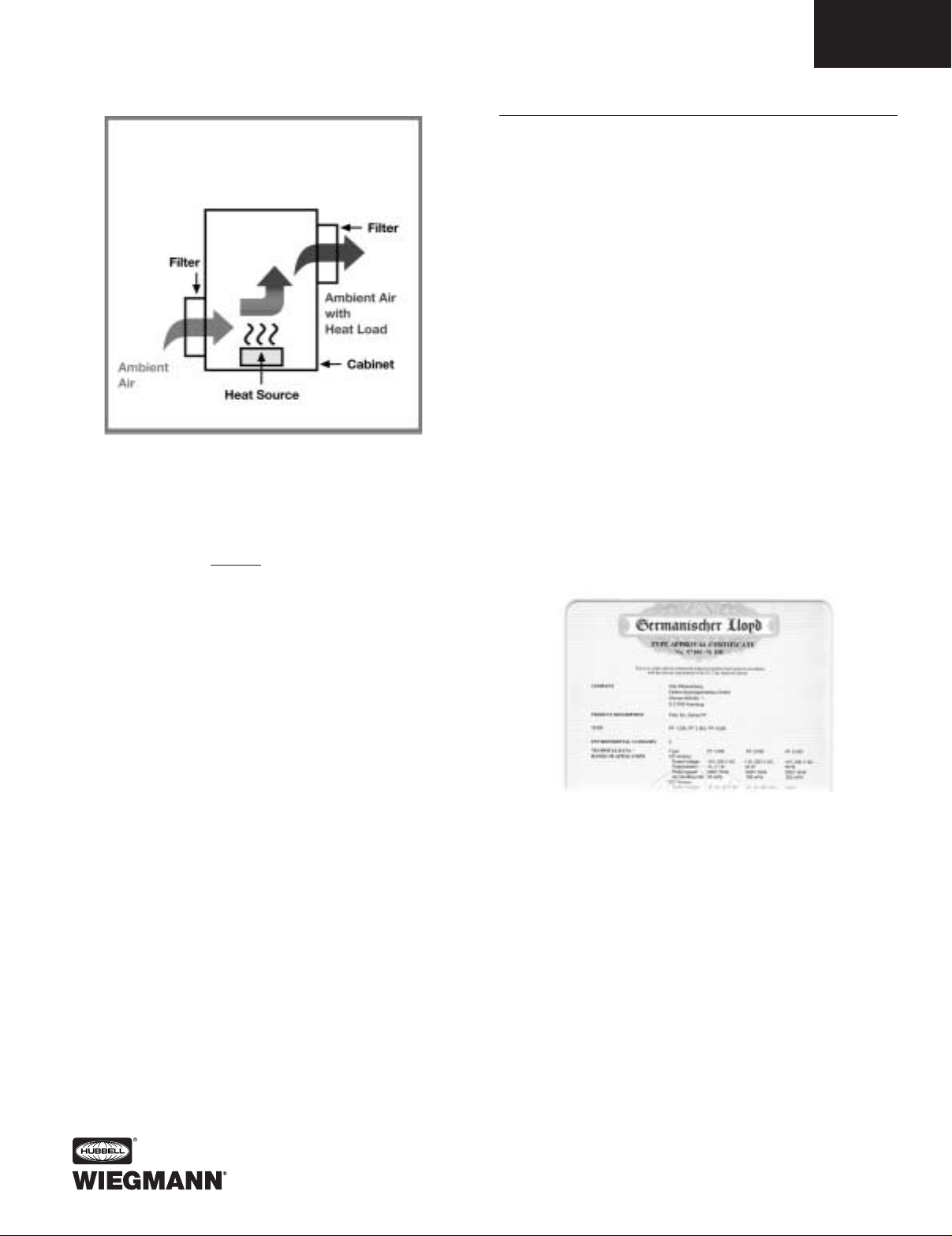
1. Natural Convection — If there is only a minimal heat
gain in your circumstance, use of louvers or grilles with
filters can be effective. This method, however, usually
provides less cooling effect than is necessary with
today’s components (Fig. 1, pg. L15).
2. Forced Convection Air Cooling — If the installation
will be in a clean, non-hazardous environment with an
acceptable ambient (outside the enclosure) temperature
range, a simple forced-air cooling system utilizing outside
air is usually adequate. Combined with an air filter, such
devices generally meet the heat removal needs of typical
electronic equipment and many electrical applications
(Fig. 2a & 2b, pg. L16). Examples of forced convection
air cooling are Filterfans™ and Box Fans.
3. Closed-Loop Cooling — In harsh environments
involving high temperatures, wash-down requirements,
heavy particulate matter or the presence of chemicals
capable of damaging components (NEMA 4 or 12
environments), ambient air must be kept out of the
enclosure. Closed-loop cooling consists of two separate
This chart demonstrates the relationship between temperature and service life.
circulation systems. One system seals out the ambient
air, cooling and recirculating clean, cool air throughout
the enclosure. The second system uses ambient air or
water to remove and discharge the heat (Fig. 3, pg. L18).
Examples of closed-loop cooling equipment employed
with electronics and process controls are air conditioners
and heat exchangers.
Heat Abduction by Natural Convection
If the ambient temperature is lower than the temperature
inside the switch cabinet, the dissipated heat escapes into
the atmosphere through the surface of the switch cabinet.
The following simple equation is used to calculate the level
of heat radiated from a switch cabinet:
PR[W} = c x A x DT
P
R
[Watt]: Radiation Power
Thermal power radiated from the surface area
of the switch cabinet into the ambience or radiated from the ambience into the switch cabinet.
C[W/m
2
K]: Coefficient of heat transmission
Radiation power per 1m2 surface area and 1K
difference in temperature. This constant is
determined by the material:
Sheet steel -5.5 W/m2K
Stainless steel -3.7 W/m2K
Aluminum -12.0 W/m2K
Plastic -0.2 W/m2K
A[m
2
]: Surface area of switch cabinet
Effective surface area of a switch cabinet
measured according to the specifications of
VDE0660, Part 506.
∆T[K]: Difference in temperature between the
ambience and inside the switch cabinet
Surface area of switch cabinet A[m2]
Heat radiation P[W]
Page 2
DATA SUBJECT TO CHANGE WITHOUT NOTICE
ENVIRONMENTAL CONTROL
TECHNICAL DATA
L15
Heat Abduction with Filterfans
™
Follow the simple equation for calculating the required
air flow volume:
V[m3/h]: Flow volume for a filter fan
Pd[Watt]: Dissipation loss
Thermal power generated inside a switch
cabinet by dissipation loss from components.
A[m2]: Difference in temperature between the
ambience and inside the switch cabinet
In the course of development, absolute priority was given
to the use of high-quality components (plastic material, fan,
filter mat) and comprehensive transparent technical data.
For this purpose we measured every Filterfan
™
and exhaust
filter in a test laboratory.
When considering the use of Filterfans™:
• Always use the Filterfan
™
to propel the cool ambient air
into the switch cabinet. This ensures that slight positive
pressure builds up inside the switch cabinet in comparison
to the ambience and that only air filtered by the Filterfan
™
flows into the switch cabinet. The air propelled into the
cabinet displaces the warm air which exits through the
exhaust filter. If, however, the air is drawn out of the switch
cabinet by suction power, unfiltered air can also enter
through gaps and components
• If you install a combination of Filterfan
™
/exhaust filter, fit
the Filterfan
™
in the lower third of the switch cabinet if
possible. The exhaust filter must be installed as near to
the top as possible to prevent heat pockets in the upper
part of the cabinet
• In switch cabinets consisting of several compartments,
the cool air capacity required should be divided among
two or more Filterfans
™
/exhaust fans. This measure helps
to ensure a more acceptable distribution of temperature
throughout the cabinet
• If you combine a Filterfan
™
with two exhaust filters, the
cool air divides into “Y” shape. In this way, with just one
additional exhaust filter you can considerably improve
the circulation inside the switch cabinet
• Install a thermostat that only trips the Filterfan
™
when
the temperature is too high. This can quite substantially
increase the service life of your filter mat
Natural Convection
Figure 1
(European Patent No. 0439667)
The Filterfan/exhaust filter is centered in the cutout
and held in place across the 4 corners. Installation
time is thus reduced from 12 minutes to virtually
ZERO.
V=
3.1(Pd)
[m3/h]
∆T
Page 3

DATA SUBJECT TO CHANGE WITHOUT NOTICE
ENVIRONMENTAL CONTROL
TECHNICAL DATA
L16
Heat Abduction with a Cooling Unit
Pfannenberg air/refrigerant cooling units operate on the
principle of the Carnot cycle. This means that the cooling
unit functions as a heat pump that “pumps” the thermal
energy abducted from the switch cabinet (heat dissipated
from the components) up to a higher level of temperature
(the ambient temperature can reach levels as high as
+131ºF). The air inside the switch cabinet is cooled down
by the evaporator and is at the same time dehumidified.
Cooling units are used if:
• The outside air cannot be used for cooling
• The required temperature inside the switch cabinet
should be equal to or lower than the required ambient
temperature
• The ambient air is extremely oily or rife with conductive dust
Steps for sizing an air conditioner — Proper selection of
an air conditioner is determined by the following criteria:
• Required cooling capacity in BTUs/hr (steps 1-4)
• Mounting requirements (top or side mounting options)
• Dimensions of air conditioner and enclosure
Figure 2a
Figure 2b
(Preferred Method)
1 Watt = 3.413 BTU/HR.
Determine the internal
heat load in Watts that
must be dissipated.
[Watts ÷ ∆T (Fº)] - [0.22 x Area (ft2)] = Watts/Fº
Capacity Required BTU/HR. Capacity Rating
1 m2= 11.76 ft
2
Calculate the exposed
surface area of the
enclosure: 2[(h x w) +
(h x d) + (w x d)] ÷ 144 =
Area (ft
2
).
1ºC or 1ºK∆T = 1.8ºF T
Determine the temperature
differential by subtracting the
maximum allowable tempera-
ture inside the enclosure (Ti)
from the maximum ambient
temperature outside
the enclosure (To).
To - Ti =
∆T
Page 4
DATA SUBJECT TO CHANGE WITHOUT NOTICE
ENVIRONMENTAL CONTROL
TECHNICAL DATA
L17
Selecting cooling units
• Ascertain the total dissipation loss from the components
installed in the switch cabinet. Take into account the
simultaneity factor, because rarely are all components in
operation at the same time
• Also take the heat radiation from the switch cabinet
into account. If T, <Ta, this must also be added to the
dissipation loss value
• Now select the necessary cooling unit in accordance
with the required refrigeration capacity, ensuring that
the cooling capacity of the cooling unit is at least equal
to the dissipation loss value. Preferable is a figure 10%
in excess of that value
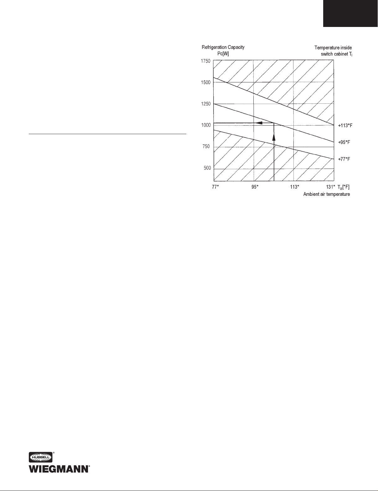
Utilizing characteristic curves for proper selection
of a cooling unit
Characteristic curves for all cooling units are available for
contacting us. These diagrams allow you to determine the
corresponding effective (useful) refrigeration capacity for any
temperature. All relevant data for our cooling units result
from tests in Pfannenberg’s own climatic chamber.
Example:
T
a
= 104ºF and Ti= 95ºF, where
T
i
[ºF]: Maximum admissible temperature inside the
switch cabinet. This value reflects the maximum
operating temperature of components installed in
the switch cabinet. This usually ranges from approx.
95ºF to 113ºF.
T
a
[ºF]: Maximum ambient temperature. Temperature
at which the switch cabinet is installed.
P
c
[Watt]: Refrigeration capacity of a cooling unit.
Only the effective or useful cooling capacity is shown.
Go to the known ambient temperature (T
a
= 104ºF) and
trace a vertical line up to the intersection with 95ºF line.
Then trace a horizontal line left of that intersection until
it meets with the ordinate (vertical axis). This point shows
the refrigeration capacity required. In this example, the
following diagram shows that the value is 1040W.
Important information on the utilization of cooling units
• The refrigeration capacity should exceed the dissipation
loss from the installed components by approximately ten
percent (10%)
• The switch cabinet must be adequately sealed to prevent
the inflow of ambient air
• Use the door contact switch to impede operation with
open doors and consequent excessive accumulation of
condensation
• Use cooling units with a generous clearance between air
inflow and air outflow to prevent poor circulation
• Attach the condensate overflow hose included in the
package of accessories supplied with the unit
• Make sure that the air inflow and air outflow in the external
circuit of the cooling unit circulates satisfactorily to ensure
that the thermal energy is released into the ambience
• When using top-mounted cooling units, make sure that
components with their own fans do not expel the air
directly into the cooling unit’s cool air outflow. This counteraction between the two airflows would otherwise substantially reduce the refrigeration capacity and could cause
heat pockets.
• Make sure that the switch cabinet stands up straight.
Otherwise the condensation cannot drain properly from
the top-mounted unit
• Setting the temperature to the lowest setting is not the
optimal solution due to condensation issues. The value
we have preset on the cooling unit is a sound compromise
between cooling the inside of the switch cabinet and the
accumulation of condensation
Page 5

DATA SUBJECT TO CHANGE WITHOUT NOTICE
ENVIRONMENTAL CONTROL
TECHNICAL DATA
L18
Cooling Control Cabinets
Most electrical & electronic control systems generate substantial amounts of heat during operation. This heat factor intensifies as controls are made more compact, perform more
functions, or are placed in more confined areas. Additional
problems are encountered when the electronic process
control system is located on-site in an industrial setting, as
opposed to a clean computer room. For instance, ambient
temperatures found in a steel mill can be locally very high.
The factory environment can be hostile to the point that
performance and effective life of electronic components are
materially reduced, or the control system fails completely.
Moisture-laden air and airborne particulate matter might be
present to adversely affect electronic components, as is true in
the paper manufacturing industry or in grain storage facilities.
Our air conditioners are designed to perform reliably under
many of these harsh conditions and to provide the cooling
and environmental protection required by sensitive electronic
production control systems.
Factors affecting model selection
Use this section as a basic outline or checklist of the various
conditions to be considered when choosing a cooling unit
for a certain application.
The following three factors must be considered when
selecting a cooling unit:
1. Internal Heat Load
This is the heat dissipated by electronic controls. It is
expressed in watts. One watt equals 3.413 BTU/hr. Thus,
to obtain the approximate cooling capacity required to
remove a specific heat load, the following formula can
be used:
Watts x 3.413 = BTU/hr
For example, a heat load of 800 watts requires an air
conditioner capable of removing at least 2,730 BTU/hr
2. Resistance to air flow in the enclosure
Air-flow is measured in cubic feet per minute (CFM).
Creating appropriate air flow requires that air pressure be
produced by a blower within the air conditioning enclosure.
Resistance to blower-produced air flow is created by
obstructions within the cabinet’s air-flow path. This resistance is called static pressure (SP) and is measured in
inches of water column.
The effect of significant resistance in the cabinet’s air flow
due to static pressure is that it produces a drop in air
pressure, or differential, from the air velocity produced by
the blower. This reduction in cool air flow will decrease the
effective capacity of the cooling unit. So when selecting
the proper cooling unit, allowances must be made for
static pressure.
3. Heat Load From the Surroundings
Ambient conditions can cause a heat gain in the enclosure.
The rated capacity of the cooling unit must be sufficient
to handle this heat gain. When evaluating the additional
heat load gained from the surroundings, consider the
following:
Insulated Cabinet — Normally, well-insulated cabinets
will not gain sufficient ambient heat to affect an air conditioner’s operation. BTU/hr ratings for our air conditioners
have been established at the maximum ambient operating
temperature of 125ºF. A substantial improvement in heat
removal occurs when operating in ambient temperatures
below 125°F.
Uninsulated Cabinets (most common) — Obviously,
this design places more of a burden on the cooling unit.
Heat is conducted to the cool side. Thus, high ambient
heat will be readily transmitted into the cooler enclosure.
To determine the additional capacity required of our air
conditioner installed in an uninsulated cabinet, the surface
square footage of the enclosure must be calculated
to obtain the total effective heat transfer area. For this
calculation, use the surface area of the sides, plus the
area of the top, and omit the bottom area of the cabinet.
Air movement outside the uninsulated cabinet will
increase the heat conducted from the ambient into the
enclosure. When there is little or no air circulation outside
the cabinet, the layer of air immediately adjacent to the
exterior cabinet walls act as an insulating film. Exterior air
movement dissipates this insulating layer of air in proportion to the velocity of the air flow. Substantial ambient air
circulation will increase the transmitted heat load imposed
on the cooling unit. If the cabinet being cooled is not
airtight, then high ambient relative humidity will adversely
affect the cooling effectiveness of the air conditioner.
When humid air infiltrates a poorly sealed enclosure,
the air conditioner is required to use up valuable BTU/hr
capacity just to condense the moisture from the internal
air. Conversely, if the cabinet is well sealed, high ambient
relative humidity has very little effect on the heat capacity
of the air conditioner.
Figure 3
Page 6

DATA SUBJECT TO CHANGE WITHOUT NOTICE
ENVIRONMENTAL CONTROL
TECHNICAL DATA
L19
Why Use a Heater?
Hubbell Wiegmann heater products protect electronic and electrical components
from temperature problems that are below acceptable tolerances. There are
obvious circumstances when extremely low ambient (outside the enclosure)
temperatures would require a heater, but there are also less apparent times that
a heater should be considered. For example, a system may run all day having its
components generate heat, but once the system shuts down for the night, the
quick drop in temperature could cause condensation and possible corrosion —
a heater could be used to maintain a safe and constant temperature.
Heater Sizing
Formula for sizing Hubbell Wiegmann enclosure heating products:
P
H
= (∆T x k x A) – Pv
Variables:
P
H
= Total power required in Watts for application.
∆T = Difference between the minimum required enclosure interior temperature
and the lowest possible exterior temperature, in degrees Kelvin.
“DT” can be calculated using the following formula:
(IT) - (ET)
1.8
= ∆T in ºKelvin
(IT) – Minimum required enclosure interior
temperature [ºF]
(ET) – Lowest possible exterior temperature [ºF]
k = Heat transmission coefficient convection of enclosure material in quiet air.
Painted Steel 0.511 W/(ft
2
ºK)
Stainless Steel 0.344 W/(ft
2
ºK)
Aluminum 1.115 W/(ft
2
ºK)
Plastic (or insulated stainless) 0.325 W/(ft
2
ºK)
A = Enclosure surface area in ft.
2
“A” can be calculated by using the
following formula (assuming a wall-mounted enclosure):
1((H/12) x (W/12)) + 2((W/12) x (D/12)) + 2((H/12 x (D/12)) = A in ft.
2
H = Height of enclosure (in inches)
W = Width of enclosure (in inches)
D = Depth of enclosure (in inches)
Pv = Existing power from installed components (Watts).
Sample with solution:
Required sizing information:
• Wiegmann Painted Steel Enclosure = N12161206 (H =16", W = 12", D = 6")
• Minimum required enclosure interior temperature in Fahrenheit=50ºF (IT)
• Lowest possible exterior temperature in Fahrenheit = -30ºF (ET)
• Existing components generating 50 Watts (Pv)
(50) - (-30)
∆T =
1.8
= 44.44
k = 0.51
A = 2((16/12) x (12/12)) + 2((12/12) x (6/12)) + 2((16/12 x (6/12)) = 4.99
P
H
= (44.44 x 0.51 x 4.99) - 50 = 63 Watts needed to heat the enclosure
H
W
D
 Loading...