

WIEDER WECCBE09920 User Manual
USER’S MANUAL
www.weiderfitness.com
Visit our website at
QUESTIONS?
As a manufacturer, we are committed to providing complete customer
satisfaction. If you have questions,
or if there are missing parts, please
call:
1-888-936-4266
Mon.–Fri. 8h00 until 18h30 EST
(excluding holidays).
Model No. WECCBE09920
Serial No.
Write the serial number in the space
above for reference.
CAUTION
Read all precautions and instructions
in this manual before using this
equipment. Save this manual for
future reference.
Serial Number
Decal
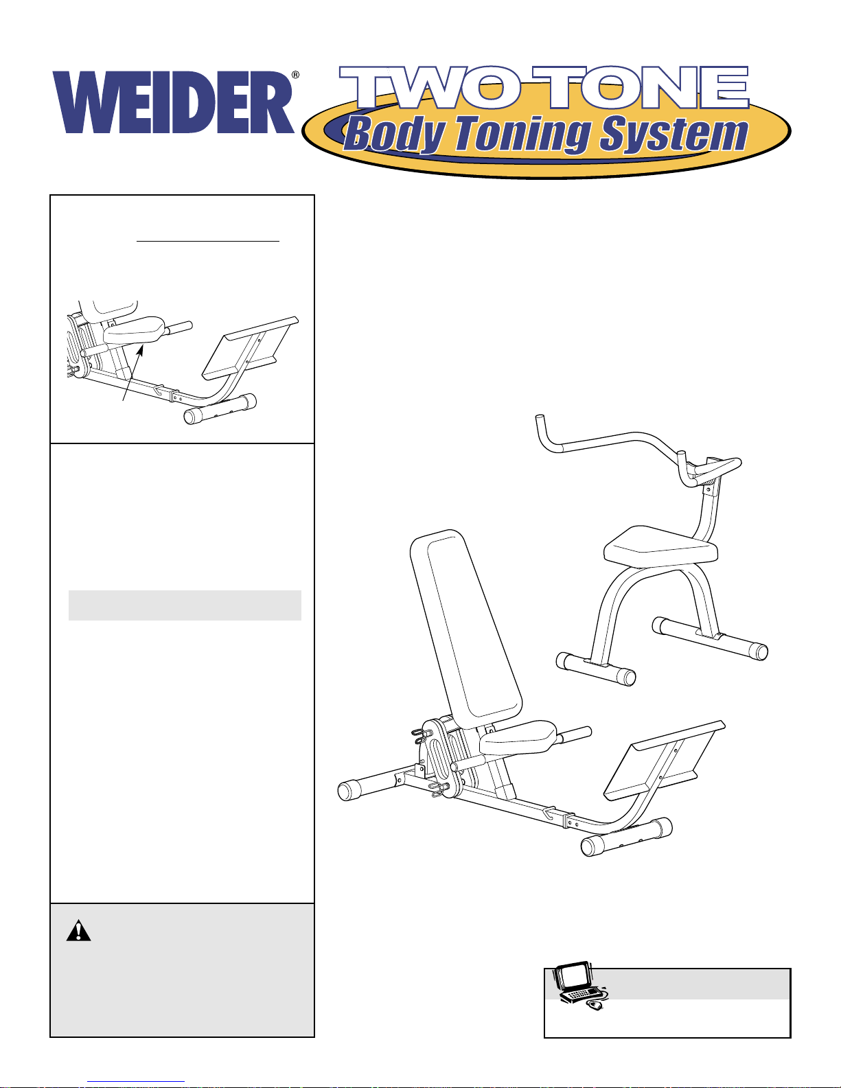
Thank you for selecting the versatile WEIDER®TWO
TONE BODY TONING SYSTEM. The TWO TONE BODY
TONING SYSTEM is designed to help you develop every
major muscle group of the body. Whether your goal is a
shapely figure, dramatic increase in muscle size and
strength, or a healthier cardiovascular system, the TWO
TONE BODY TONING SYSTEM will help you achieve the
specific results you want.
For your benefit, read this manual carefully before
using the WEIDER
®
TWO TONE BODY TONING SYS-
TEM. If you have additional questions, call our Customer
Service Department toll-free at 1-888-936-4266, Monday
through Friday, 8h00 until 18h00 Eastern Time (excluding
holidays). To help us assist you, please mention the product model number (WECCBE09920) and the serial number
found on a decal attached to the body toning system (see
the front cover of this manual).
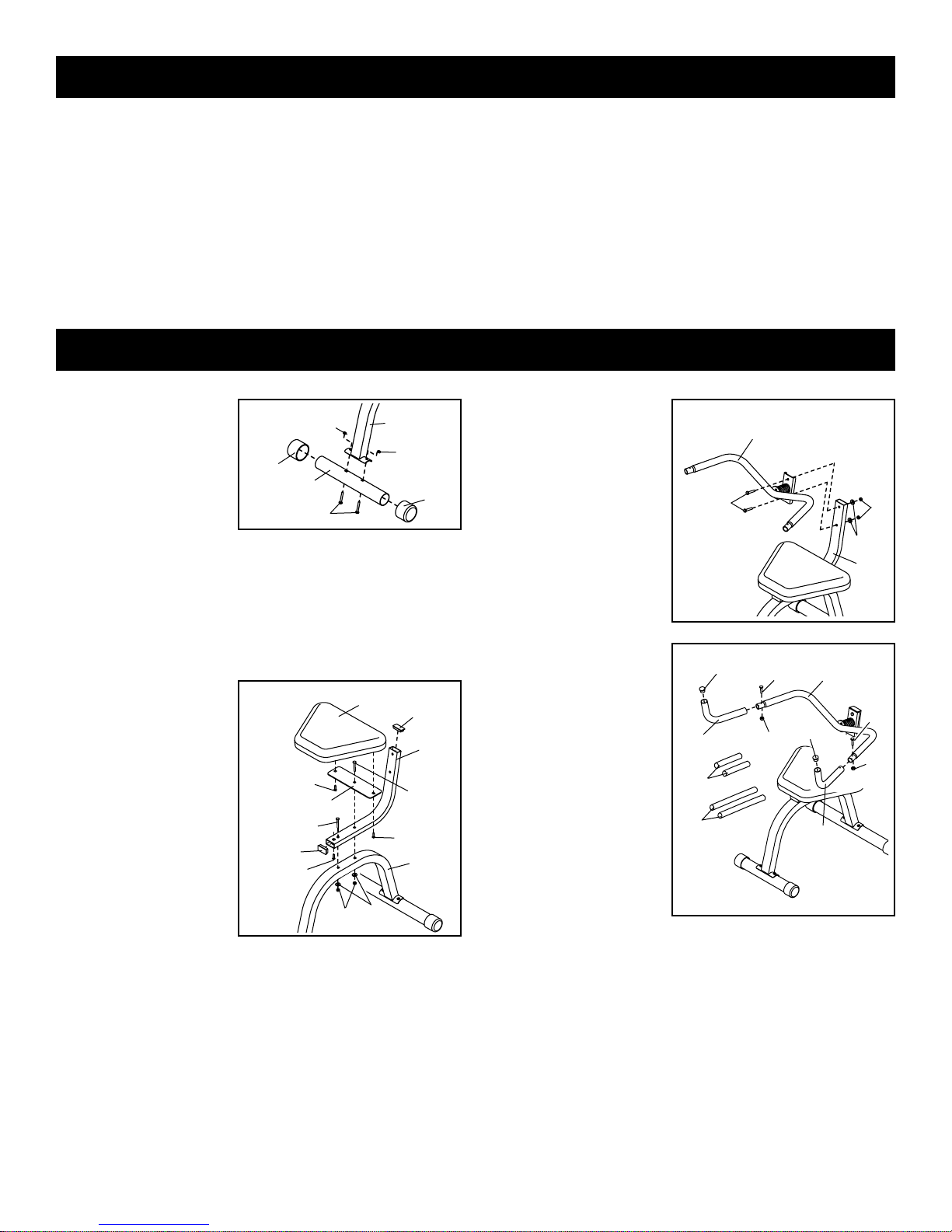
1. Press two 2” Round
Outer Caps (23)
onto each of the two
Front Stabilizers (9)
and the two Rear
Stabilizers (not
shown). Note: The
Front Stabilizers
are shorter than the Rear Stabilizers.
Attach a Front Stabilizer (9) to the Ab Leg (12) with two
M8 x 63mm Carriage Bolts (31) and two M8 Nylon
Locknuts (34). Attach a Rear Stabilizer (not shown) to
the other end of the Ab Leg in the same manner.
2. Insert an M8 x
77mm Carriage Bolt
(41) into the center
hole in the Large
Support Plate (14).
Attach the Large
Support Plate to the
Large Seat (13) with
two M6 x 16mm
Button Screws (40).
Press a 1” x 2” Inner
Cap (30) into each
end of the Seat
Frame (15).
Insert an M8 x 77mm Carriage Bolt (41) into the indicated hole in the Seat Frame (15). Insert the M8 x
77mm Carriage Bolt in the Large Support Plate (14)
through the rear hole in the Seat Frame.
Attach the Large Seat (13) to the Seat Frame (15) with
the M6 x 16mm Button Screw (40).
Secure the two M8 x 77mm Carriage Bolts (41) to the
Ab Leg (12) with two M8 Washers (35) and two M8
Nylon Locknuts (34).
1
3. Hold the Ab Frame
(11) as shown. Slide
two M8 x 40mm
Button Bolts (33)
through the Ab
Frame and the Seat
Frame (15). Secure
the Bolts with two
M8 Washers (35)
and two M8 Nylon
Locknuts (34).
4. If there are M6 x
34mm Button Bolts
(47) in the ends of
the Ab Frame (11),
remove them.
Wet the Ab Frame
(11) and the inside of
the Short Sleeves
(48) with soapy
water. Slide the two
Short Sleeves onto
the Ab Frame, making sure the angled
ends face each
other.
Hold the Ab Handlebars (10) as shown and attach
them to the Ab Frame (11) with the two M6 x 34mm
Button Bolts (47) and two M6 Nylon Locknuts (44).
Press a 28.6mm Round Inner Cap (16) into each Ab
Handlebar.
Wet the Ab Handlebars (10) and the inside of the Long
Sleeves (49) with soapy water. Slide the two Long
Sleeves onto the Ab Handlebars and the Ab Frame
(11), so that they cover the M6 x 34mm Button Bolts
(47) and the M6 Nylon Locknuts (44). Make sure the
angled ends of the Long Sleeves are by the 28.6mm
Round Inner Caps (16).
2
3
11
33
23
23
34
12
34
31
13
15
14
41
41
40
12
40
40
30
34
35
9
35
34
30
15
4
10
10
11
16
44
47
47
48
49
44
16
Before You Begin
Assembly—AB TILT & TONE
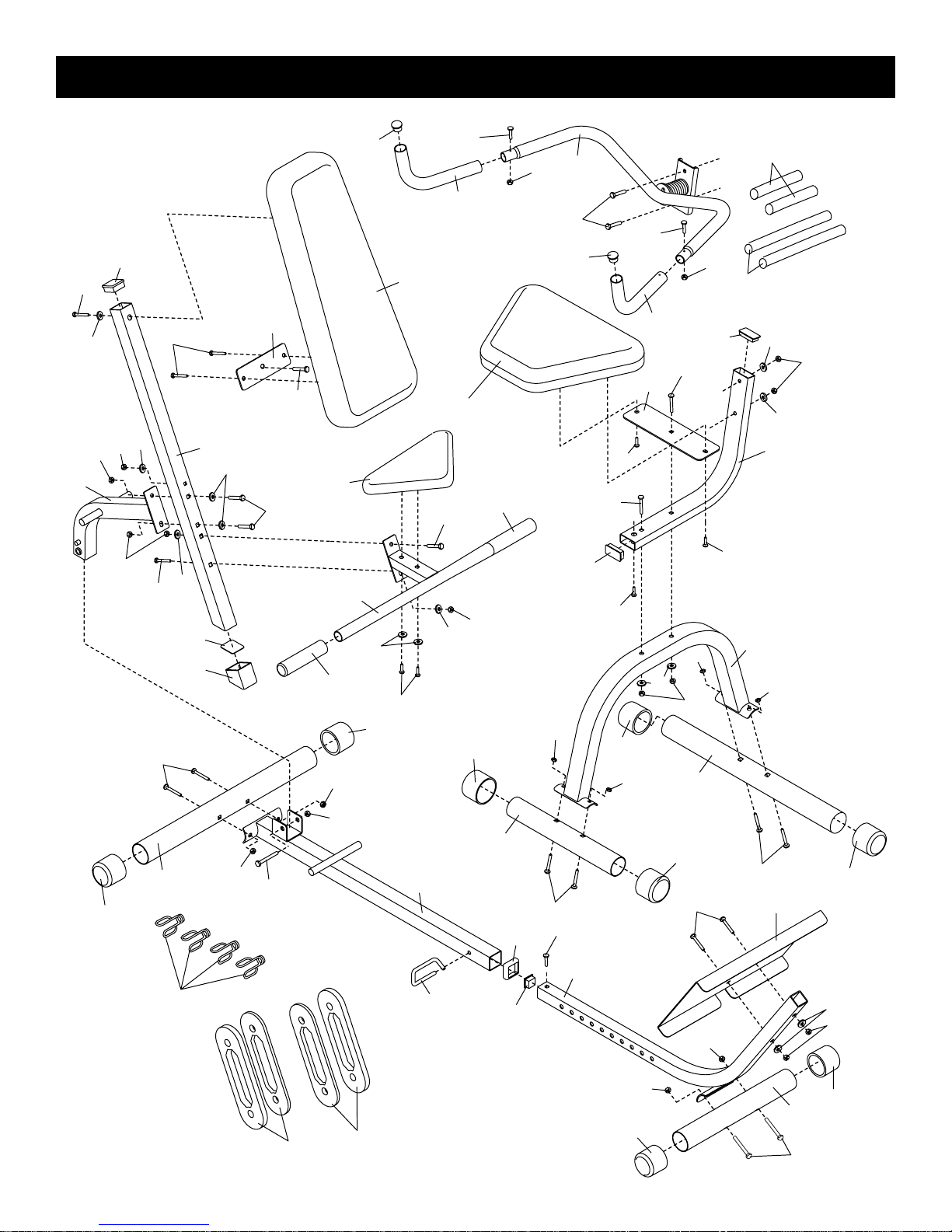
Exploded Drawing—Model No. WECCBE09920
R0402A
43
38
7
34
24
44
34
38
42
31
40
35
19
18
42
35
10
13
47
23
34
22
44
34
33
11
16
30
41
40
40
23
34
47
10
14
35
41
34
34
48
44
49
30
8
35
34
35
15
40
12
34
16
4
20
45
1
35
29
42
21
38
22
46
23
34
8
23
5
34
37
25
36
28
9
23
2
32
34
26
17
27
31
39
3
34
23
31
6
23
35
34
23
9
31
 Loading...