

Wiedenmann Terra Spike XF 20-6, Terra Spike XF 20-8, Terra Spike XF 20-7 Operating Instructions

Wiedenmann
Translation of original
operating instructions
Deep Aerator
Terra Spike
XF 20-6 / XF 20-7
and XF 20-8
860.003
Effective January 2006
860 99 09
Wiedenmann GmbH - D 89192 Rammingen
Tel. No.: 0049 / 7345 / 953-02 Fax No.: 0049 / 7345 / 953233
2
All information, illustrations and specifications in this manueal arw based on the latest information
available at the time of publication. The right is reserved to make changes at any time without notice.

Introduction
READ THIS MANUAL carefully to learn how to operate and service your
machine correctly. Failure to do so could result in personal injury
or equipment damage. This manual and safety signs on your machine
may also be available in other languages (see your dealer to order).
THIS MANUAL SHOULD BE CONSIDERED a permanent part of your machine and
should remain with the machine when you sell it.
MEASUREMENTS in this manual are given in both metric and customary
U.S. unit equivalents. Use only correct repacement parts and
fasteners. Metric and inch fasteners may require a specific metric
or inch wrench.
RIGHT - HAND AND LEFT - HAND sides are determined by facing the
direction the implement will travel when going forward.
WRITE PRODUCT IDENTIFICATION NUMBERS (P.I.N.) in the Specification or
Identification Numbers section. Accurately record all the numbers to
help in tracing the machine should it be stolen. Your dealer also
needs these numbers when you order parts. File the identification
numbers in a secure place away from the machine.
BEFORE DELIVERING THIS MACHINE, your dealer performed a pre-delivery
inspection to ensure best performance.
THIS MACHINE IS DESIGNED SOLELY for use in customary agricultural and
forestry operations, for lawn and park care, i.e. collecting grass,
leaves and paper (“INTENDED USE“).
Use in any other way is considered as contrary to the intended use.
The manufacturer accepts no liability for damage or injury resulting
from this misuse, and these risks must be borne solely by the user.
Compliance with and strict adherence to the conditions of operation,
service and repair as specified by the manufacturer also constitute
essential elements for the intended use.
THIS MACHINE SHOULD BE OPERATED, serviced and repaired only by persons
familiar with all its particular characteristics and acquainted with
the relevant safety rules (accident prevention).
The accident prevention regulation, all other generally recognized
regulations on safety and occupational medicine and the road traffic
regulations must be observed at all times.
Any arbitrary modifications carried out on this material collection
system will relieve the manufacturer of all liability for any
resulting damage or injury.
All information, illustrations and specifications in this manueal arw based on the latest information
available at the time of publication. The right is reserved to make changes at any time without notice.
3

C O N T E N T S Page
* * * * * * * * * * * * * * * * * * * * * * * * * * * * * * * * * * * * * * * * * * * * * * * * * * *
1.0. Safety...................................................... 5-13
1.1. Safety Decals........................................ 10&12
1.2. Safety Equipment..................................... 13
2.0. Construction method of Operation............................ 14
2.1. Construction......................................... 14
2.2. Method of Operation.................................. 14
2.3. Product Observating.................................. 14
3.0. Transport................................................... 15&16
3.1. General.............................................. 15
3.2. Transporting Terra Spike............................. 16
4.0. Connecting to the Tractor................................... 17&20
4.1. General.............................................. 17
4.2. Assembly of bottom connecting rod plates............. 18
4.3. Connecting to the Tractor............................ 19
4.4. Adapting the PTO Shaft............................... 20
5.0. Detaching from Tractor...................................... 21
5.1. General.............................................. 21
5.2. Resting Terra Spike.................................. 21
6.0. Operating................................................... 22&31
6.1. General.............................................. 22
6.2. Indicating and Adjustment Elements................... 23
6.3. Mounting the Tools................................... 24&26
6.4. Adusting the TERRA SPIKE............................. 27&29
6.5. Assemble drive....................................... 30&31
7.0. Operation................................................... 32&35
7.1. General.............................................. 32
7.2. Correct Sequence for engaging........................ 32
7.3. Malfunctions and Remedy.............................. 33&34
7.4. Check and clean the stop buffer...................... 35
8.0. Maintenance................................................. 36&52
8.1. General.............................................. 36
8.2. Maintenance and Inspection List...................... 37
8.3. Lubrication.......................................... 38
8.4. Cleaning TERRA SPIKE................................. 39
8.5. Changing the oil of the gear unit.................... 40
8.6. Setting cleaner...................................... 40
8.7. Replacing the buffer................................. 41
8.8. Change tine holders.................................. 42
8.9. Replace tension spring............................... 43
8.10. Adjust tension spring................................ 44
8.11. Check and tense the power belt....................... 45
8.12. Changing driving belt................................ 46&47
8.13. Change the tension spring for the
central adjustment.................................. 48&49
8.14. Hydraulic system..................................... 50
8.15. Hydraulic circuit diagram for
hydraulic depth adjustment.......................... 51
8.16. Dismounting/Disposal................................. 52
8.17. Modification......................................... 52
9.0. Additional Equipment........................................ 53
10.0. Specification............................................... 54&61
4
All information, illustrations and specifications in this manueal arw based on the latest information
available at the time of publication. The right is reserved to make changes at any time without notice.
Recognize safety information
This is the safety-alert
symbol. When you see this
symbol on yourmachine or in
this manual, be alert to the
potential for personal injury.
Follow recommended precautions
and safe operating practices.
Follow safety instuctions
Carefully read all safety
messages in this manual and on
your machine safety signs. Keep
safety signs in good condition.
Replace missing or damaged
safety signs. Be sure new
equipment components and repair
parts include the current
safety signs.Replacement safety
signs are available from your
dealer.
1.0. Safety
Learn how to operate the
machine and to use controls
properly. Do not let anyone
operate without instruction.
Keep your machine in proper
working condition. Unauthorized
modifications to the machine
may impair the fuction and/or
safety and affect machine life.
If you do not understand any
part of this manual and need
assistance, contact your
dealer.
All information, illustrations and specifications in this manueal arw based on the latest information
available at the time of publication. The right is reserved to make changes at any time without notice.
5
Observe road traffic regulations
Always observe local road
traffic regulations when using
public roads.
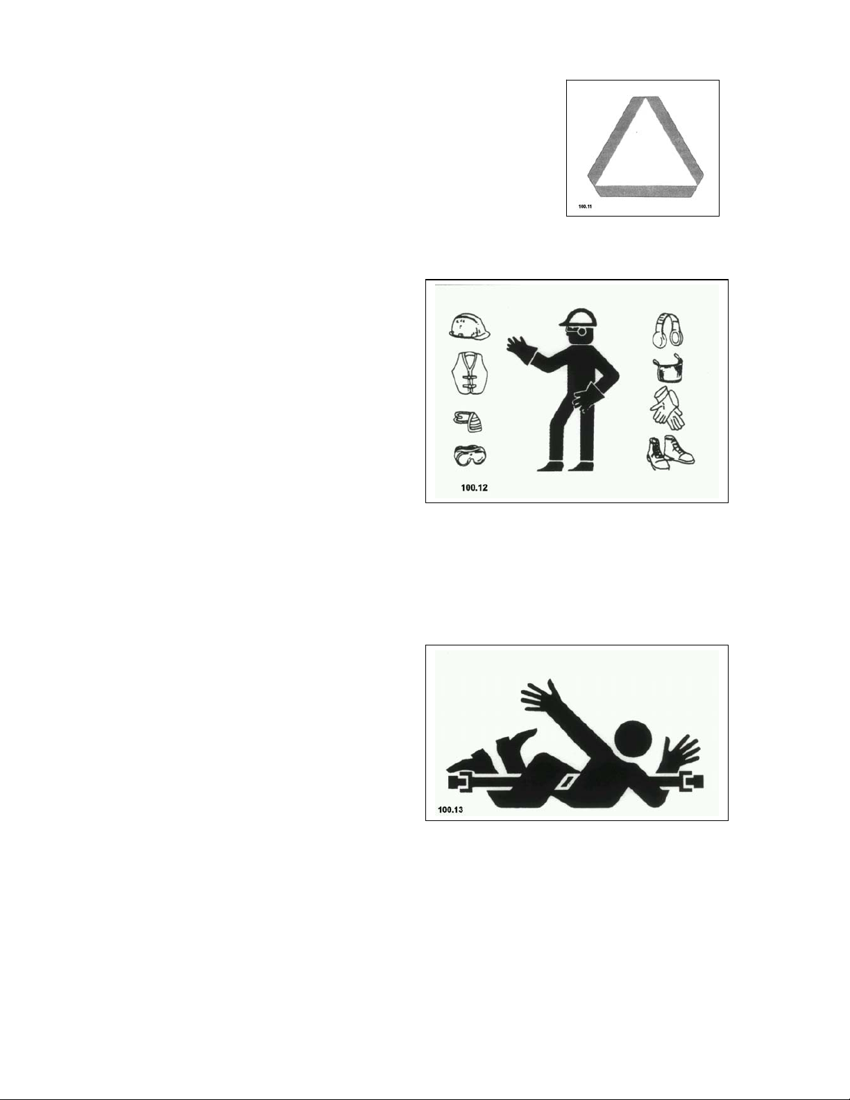
Wear protective clothing
Wear close fitting clothing and
safety equipment appropriate to
the job.
Prolonged exposure to loud
noise can cause impairment or
loss of hearing.
Wear a suitable hearing
protective device such as
earplugs to protect against
objectionable or uncomfortably
loud noises.
Operating equipment safety
requires the full attention of
the operator. Do not wear radio
or music headphones while
operating machine.
1.0. Safety
Stay clear of rotating drivelines
Entanglement in rotating
driveline can cause serious
injury or death.
Keep tractor master shield and
driveline shields in place at
all times. Make sure rotating
shields turn freely.
Wear close fitting clothing.
Stop the engine and be sure PTO
driveline is stopped before
making adjustments,
connections, or cleaning out
PTO driven equipment.
6
All information, illustrations and specifications in this manueal arw based on the latest information
available at the time of publication. The right is reserved to make changes at any time without notice.

Guard and shields
Keep guards and shields in
place all the times. Ensure
that they are in good condition
and installed correctly.
Always disengage the driveline,
turn off engine and remove key
before removing any guards or
shields.
Keep hands, feet and clothing
away from moving parts.
Avoid high - pressure fluids
Escaping fluid under pressure
can penetrate the skin causing
serious injury.
Avoid the hazard by relieving
pressure before disconnecting
hydraulic or other lines.
Tighten all connections before
applying pressure.
Search for leaks with a piece
of cardboard. Protect hands and
body from high pressure fluids.
If an accident occurs, see a
doctor immediately. Any fluid
injected into the skin must be
surgically removed within a few
hours or gangrene may result.
Doctors unfamiliar with this
type of injury should reference
a knowledgeable medical source.
1.0. Safety
All information, illustrations and specifications in this manueal arw based on the latest information
available at the time of publication. The right is reserved to make changes at any time without notice.
7
Use safety lights and devices
Prevent collisions between
other road users, slow moving
tractors with attachments or
towed equipment, and selfpropelled machines on public
roads. Frequently check for
traffic from the rear,
especially in turns, and use
hand signals or turn signal
lights.
Use headlights, flashing
warning lights, and turn
signals day and night. Follow
local regulations for equipment
lighting and marking. Keep
lighting and marking visible
and in good working order.
Replace or repair lighting and
marking that has been damaged
or lost. An implement safety
lighting kit is available from
your dealer.
1.0. Safety
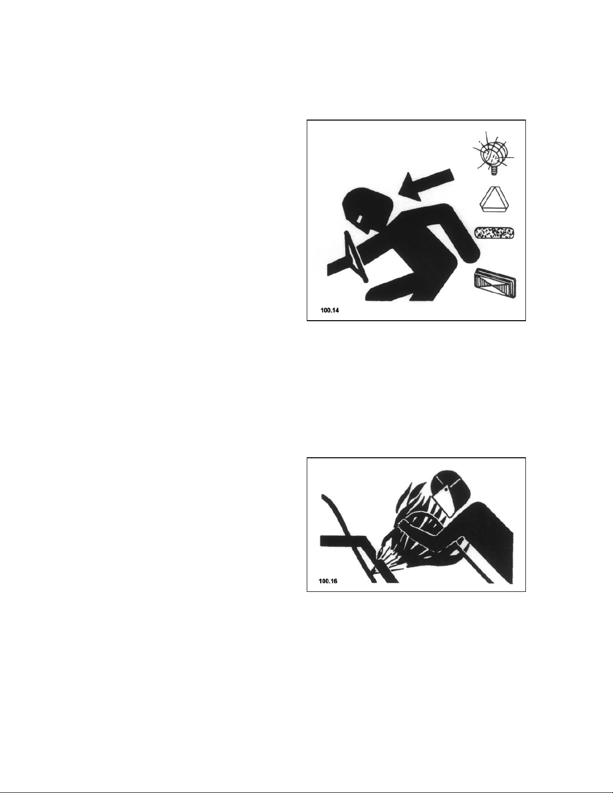
Avoid heating near pressurized fluid lines
Flammable spray can be
generated by heating near
pressurized fluid lines,
resulting in severe burns to
yourself and bystanders. Do not
heat by welding, soldering,
using a torch near pressurized
fluid lines or other flammable
materials. Pressurized lines
can be accidentally cut when
heat goes beyond the immediate
flame area.
8
All information, illustrations and specifications in this manueal arw based on the latest information
available at the time of publication. The right is reserved to make changes at any time without notice.
1.0. Safety
Remove paint before welding or heating
Avoid potentially toxic fumes
and dust.
Hazardous fumes can be
generated when paint is heated
by welding, soldering, or using
a torch.
Do all work outside or in a
well ventilated area. Dispose
of paint and solvent properly.
Remove paint before welding or
heating:
x If you sand paint, avoid
breathing the dust. Wear an
approved respirator.
x If you use solvent or paint
stipper, clean with soap and
water before welding. Remove
solvent or paint stripper
containers and other
flammable material from area.
Allow fumes to disperse at
least 15 minutes before
welding or heating.
All information, illustrations and specifications in this manueal arw based on the latest information
available at the time of publication. The right is reserved to make changes at any time without notice.
9
1.1. Safety Decals
Pictorial safety signs
At several important places on
this machine safety signs are
affixed in order to signify
potential danger. The hazard is
identified by a exclamation
point in a warning triangle. An
adjacent pictorial provides
information on how to avoid
personal injury. These safety
signs, their placement on the
nachine and a brief explanatory
text are shown below.
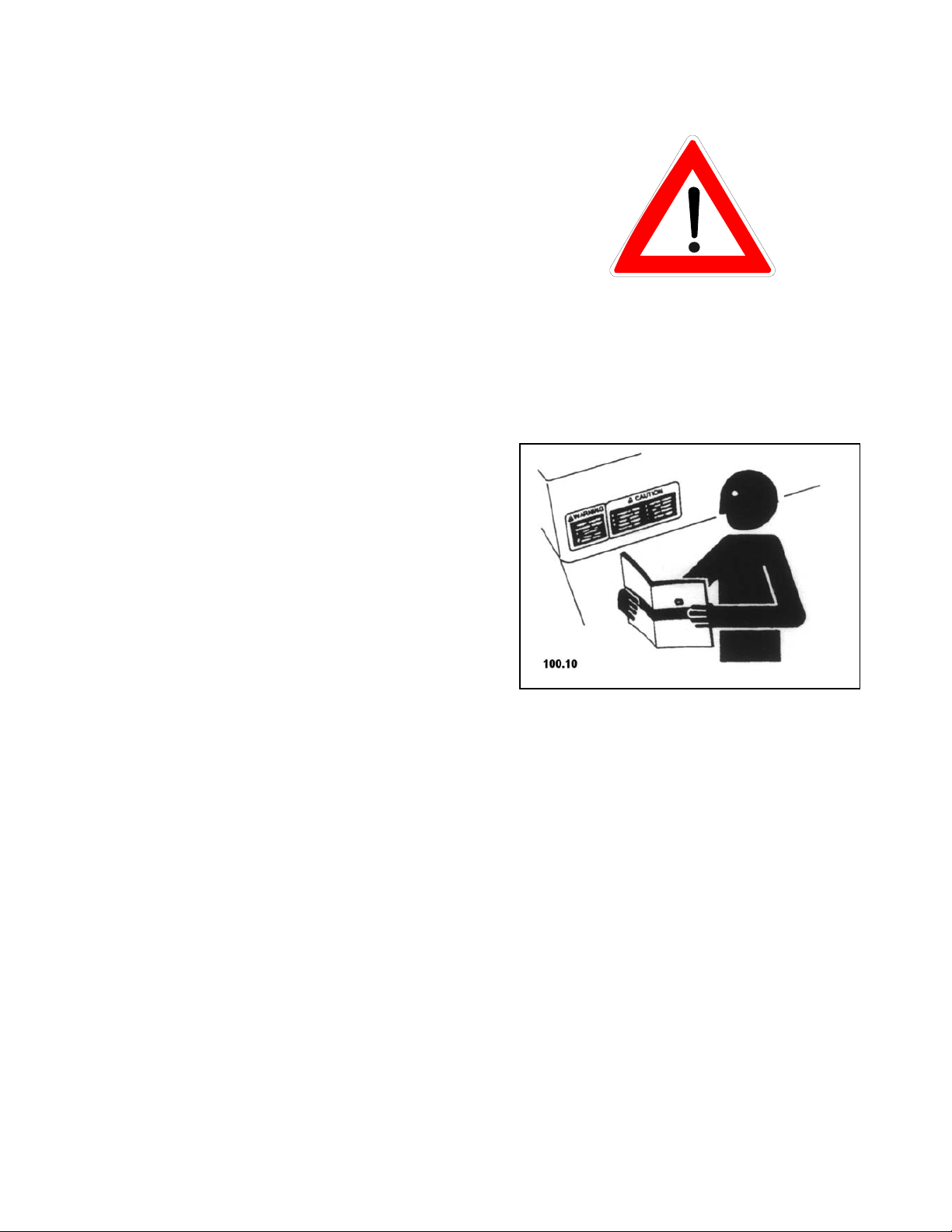
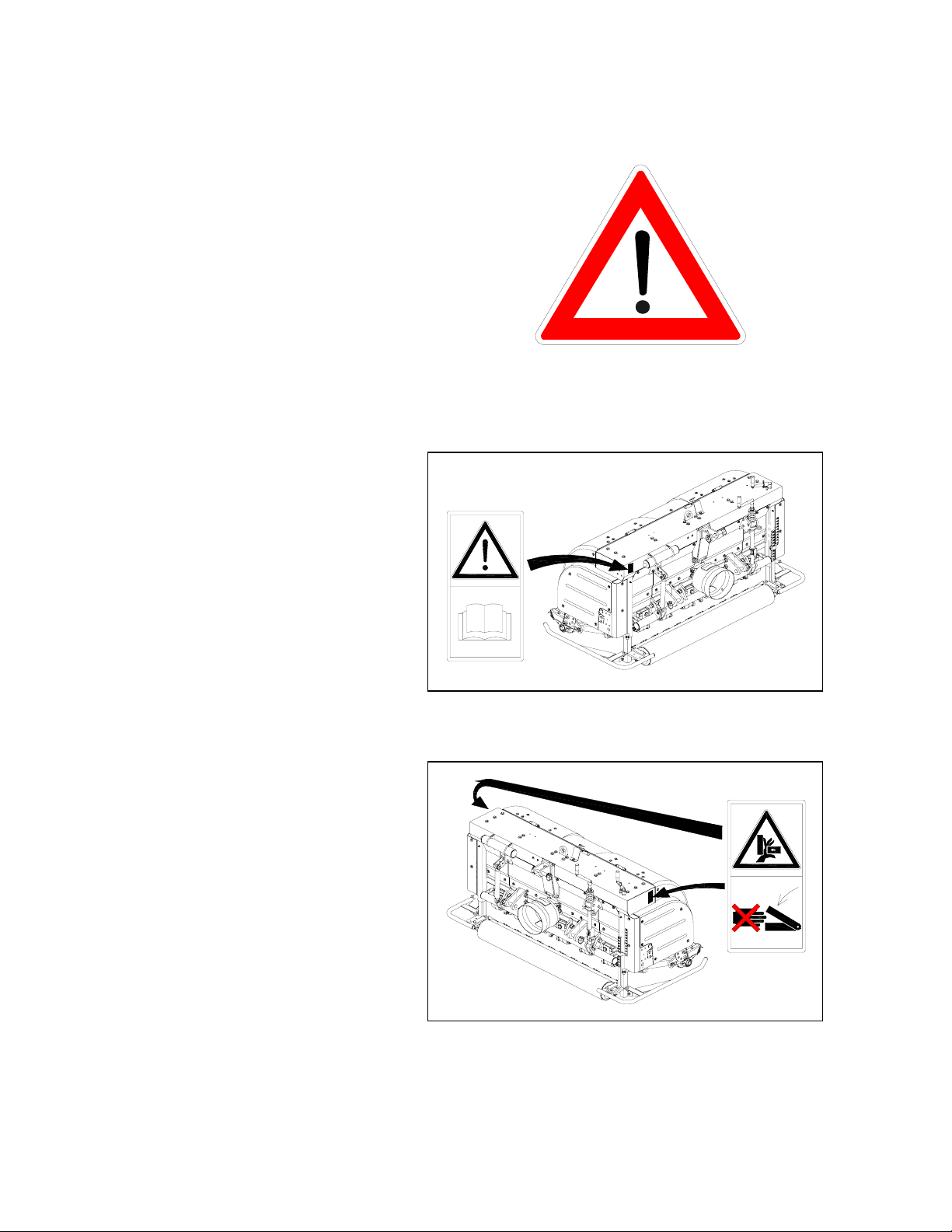
Operator’s manual
This operator’s manual
contains all important
information necessary for
safe machine operation.
Carefully observe all
safety rules to avoid
accidents.
1.0. Safety
Protectors
Never reach into areas of
crushing hazard as long
as any parts may move.
860.01
860.02
10
All information, illustrations and specifications in this manueal arw based on the latest information
available at the time of publication. The right is reserved to make changes at any time without notice.
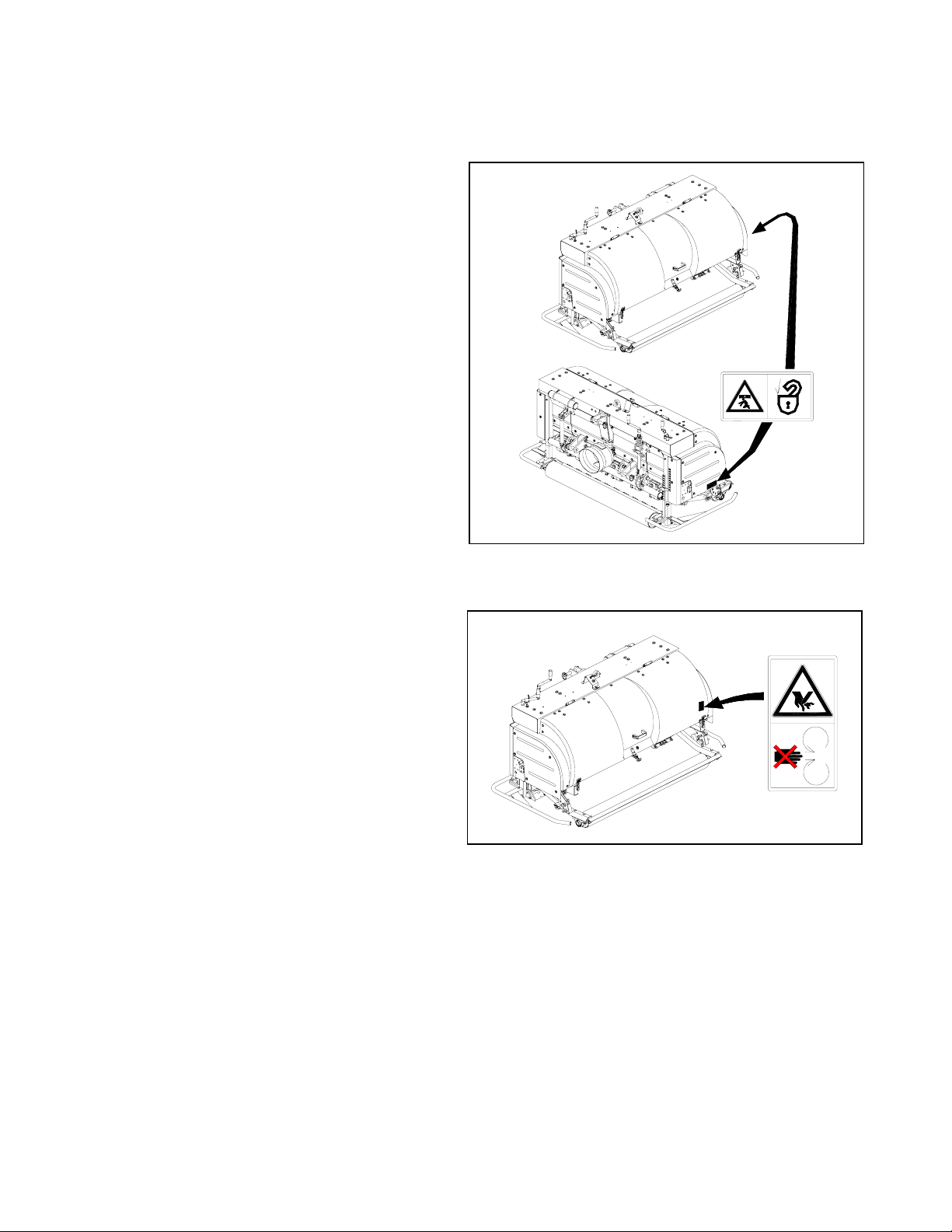
1.1. Safety Decals
Parking position
Before parking fix rear
roller with ring pins and
secure it.
1.0. Safety
Tools
Never touch moving parts
of the machine.
Wait until they have come
to a complete standstill.
860.61
860.04
All information, illustrations and specifications in this manueal arw based on the latest information
available at the time of publication. The right is reserved to make changes at any time without notice.
11
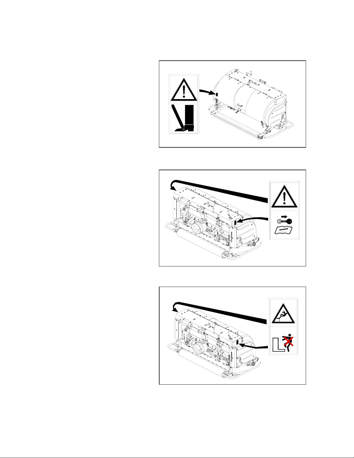
1.1. Safety Decals
Tools
Be careful to avoid
cutting of foot.
Service
Before performing service
or repair work, turn off
engine and remove key.
1.0. Safety
860.05
Operation
Do not climb onto the
machine while the engine
is running.
RISK OF FALLING !!!
860.06
860.69
12
All information, illustrations and specifications in this manueal arw based on the latest information
available at the time of publication. The right is reserved to make changes at any time without notice.
1.0. Safety
1.2. Safety Equipment
GENERAL SAFETY SIGN REQUIREMENTS
A safety sign with the following safety practices or similar set of messages shall be
provided on the machine. The label should be visible to an operator’s position, if possible.
a) Read the operator’s manual.
b) Do not operate the machine without guards, shield, and safety devices in place and
working.
c) Do not operate the machine when children and others are around.
d) Do not allow operation of the machine by untrained personnel.
ATTENTION - DANGER !
Never use TERRA SPIKE without safety equipment. Otherwise,
you expose yourself and others to extreme danger.
Moving parts may cause serious injuries.
Where to Find Safety Equipment on your Machine
D
C
A
E
B
D
A
860.86
A = Screwed fenders right / left as
spacers.
B = Back roller with arms locked with
ring pin and secured.
C = Hinged hood, secured by a lock
and holders.
All information, illustrations and specifications in this manueal arw based on the latest information
available at the time of publication. The right is reserved to make changes at any time without notice.
D = Cover removable by ring tools only.
E = Protective bowl for universal-joint
shaft connection can be only
removed using a tool
13

2.0. Construction and Method of Operation
2.1. Construction
TERRA SPIKE consists of
the following parts:
x Welded machine body
x Drive
x Adjustable tools
2.2. Method of Operation
TERRA SPIKE is hauled by the
tractor and driven by means of
a PTO shaft.
The T-gears and the lateral
drives with V-ribbed belts
power the drive. The staggered
arrangement of crankshafts is
what causes the tines to move.
The moving tines are forced
into the soil.
The angle of entry is
adjustable.
2.3. Product observation
We are bound law to observe
our products starting with
the delivery.
With an entry angle of 90°
at low speed the punched
holes are almost vertical.
With a smaller entry angle,
the soil displacement or
fracturing is
greater due to the forward
movement. This breaks up the
soil. (Effective down to
70°)
This serves your safety.
Please immediately inform
us about:
x Defects of the dafety devices.
x Repeated malfunctions.
x Altered setting.
x Problems in handling
the TERRA SPIKE.
14
All information, illustrations and specifications in this manueal arw based on the latest information
available at the time of publication. The right is reserved to make changes at any time without notice.

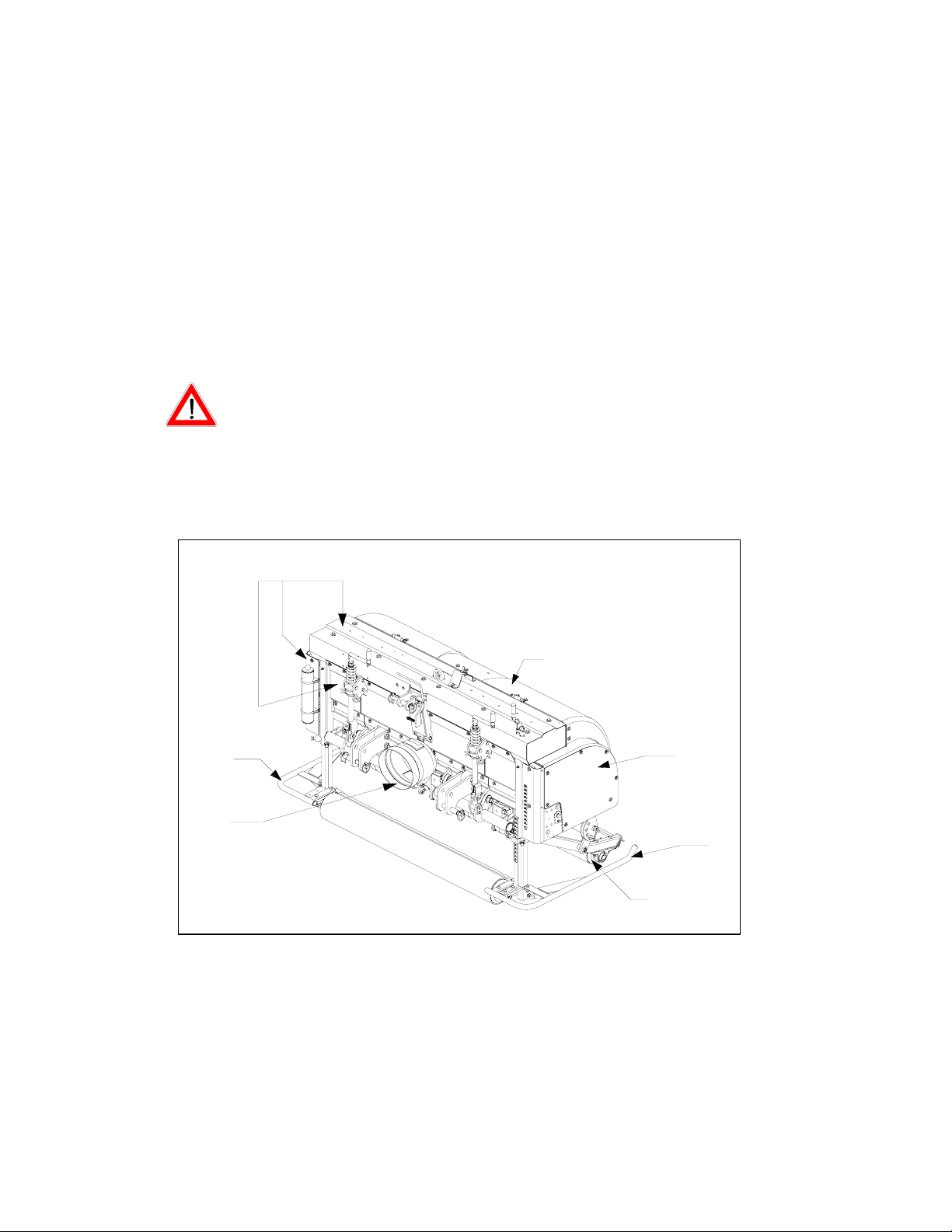
3.1. General
CAUTION DANGER !
° TERRA SPIKE is delivered
fastened to a shipment
frame.
° Only use a forklift with
sufficient load-carrying
capacity.
° Keep well clear of lifted
loads. There is danger to
your life if the load
crashes down.
Improper transport and mounting
of TERRA SPIKE may cause:
x Injury to persons
3.0. Transport
x Demage to property.
Pay special attention to the
driving direction when
lifting TERRA SPIKE with
the shipment frame.
We will not accept any
liability for damage resulting
from improper handling.
All information, illustrations and specifications in this manueal arw based on the latest information
available at the time of publication. The right is reserved to make changes at any time without notice.
15
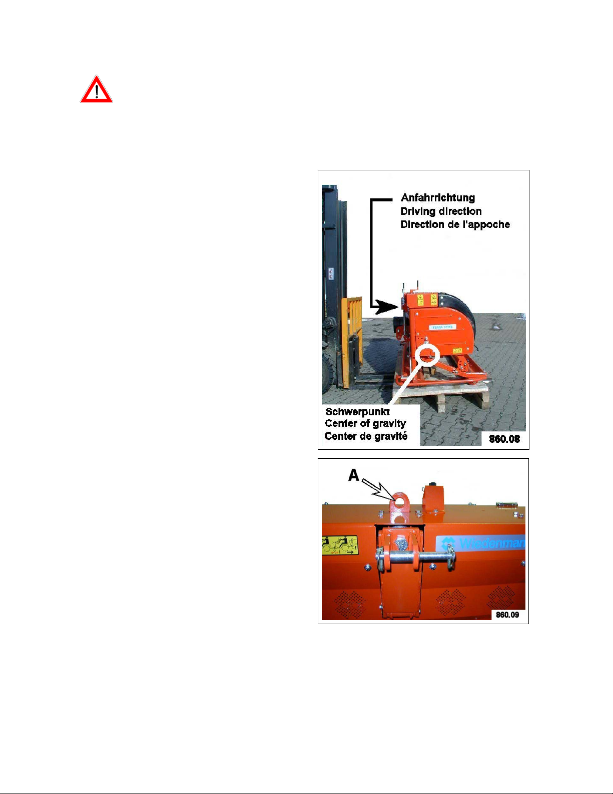
3.2. Transporting TERRA SPIKE
CAUTION DANGER !
Watch out when cutting
through the taut bands.
There is a risk of being
injured by the suddenly
opening bands.
Transport Using a Forklift
If TERRA SPIKE is still
fastened to the shipment frame:
x Insert the fork under the
shipment frame
x Unload TERRA SPIKE from
the carrier vehicle when
balanced.
3.0. Transport
x Cut through the taut bands.
x Connect TERRA SPIKE to
the tractor and lift it from
the shipment frame.
(See item 4.2.)
Transport Using a Crane
x Fasten ropes or belts at ring
screw (A) only,
x Unload TERRA SPIKE when
suspended reliably.
Note:
Immediately inform in writing
the transport company and
Wiedenmann GmbH or the supplier
about shipping damage or missing
parts.
16
All information, illustrations and specifications in this manueal arw based on the latest information
available at the time of publication. The right is reserved to make changes at any time without notice.

4.0. Connecting to the Tractor
4.1. General
Always pay attention to:
x The load of the three point
hitch.
Connect / disconnect
TERRA SPIKE only with:
x The engine turned off
x Disengate PTO shaft
x With fixed and secured back
roller (in parking/stand
position)
Use TERRA SPIKE only with:
x the special PTO shaft
assigned to TERRA SPIKE
x covered PTO shaft and
protected power-take-off
shaft.
Rest TERRA SPIKE on the
front roller (A) and
back roller (B) only.
All information, illustrations and specifications in this manueal arw based on the latest information
available at the time of publication. The right is reserved to make changes at any time without notice.
17
4.0. Connecting to the Tractor
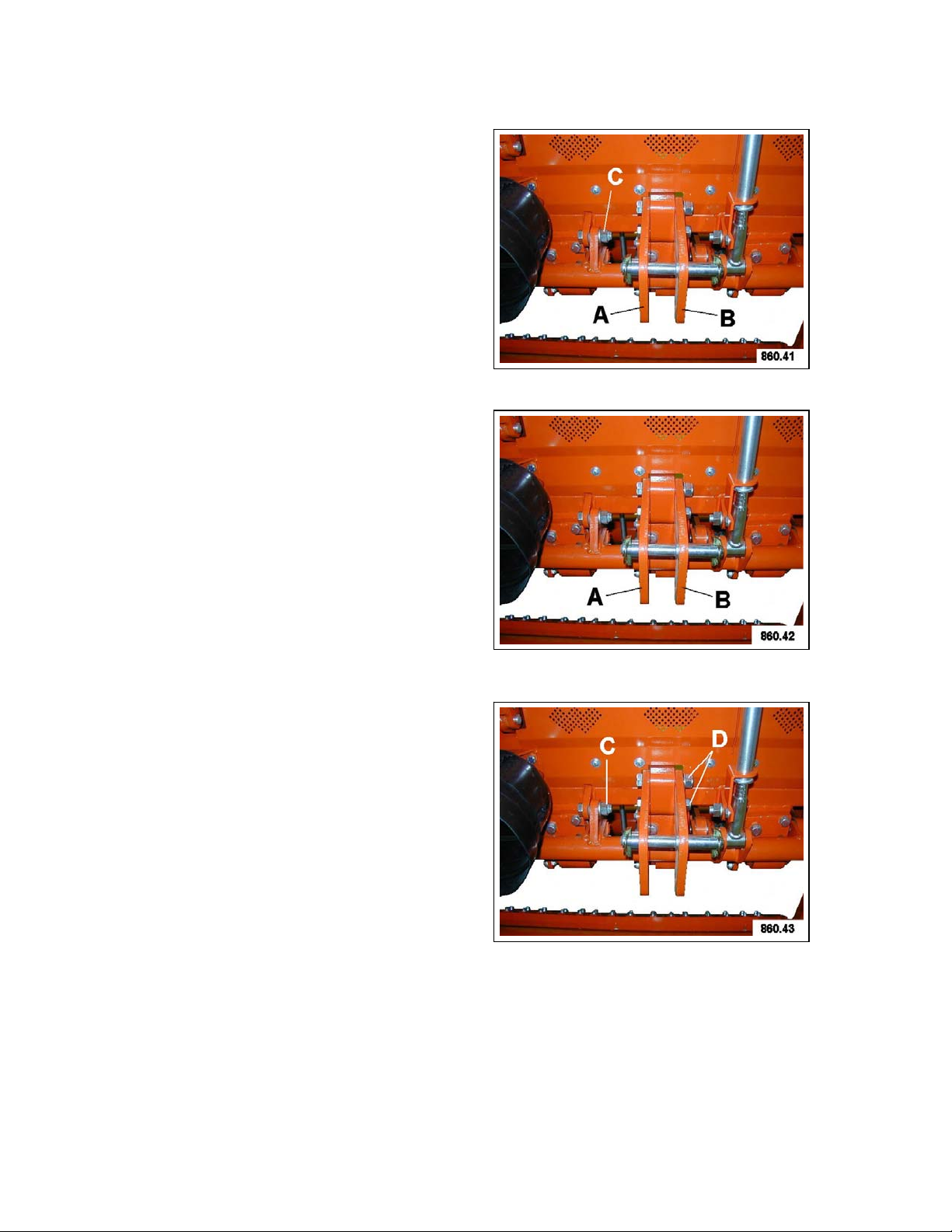
4.2. Assembly of bottom connecting rod plates
For replacement of connecting
plates (A and B), the screw
connection (C) must be released.
When assembling the connecting
plates for Cat. I/II, ensure that
connecting plate (B) with the
large bores is always on the
outside.
Mounting screws (D) for
connecting plates (A and B)
must be tightened to a torque
of 300 Nm.
Mounting screws (C) must be
tightened to a torque of 300 Nm.
Secure all nuts with Loctite
(No.270).
18
All information, illustrations and specifications in this manueal arw based on the latest information
available at the time of publication. The right is reserved to make changes at any time without notice.
4.0. Connecting to the Tractor
4.3. Connecting to the tractor
Prerequisite for connecting:
x a three-point hitch.
NOTE:
° if possible use the lower
location hole for mounting
the lower guide rod.
This provides the maximum
lifting distance.
° observe the bending angle
of the PTO shaft.
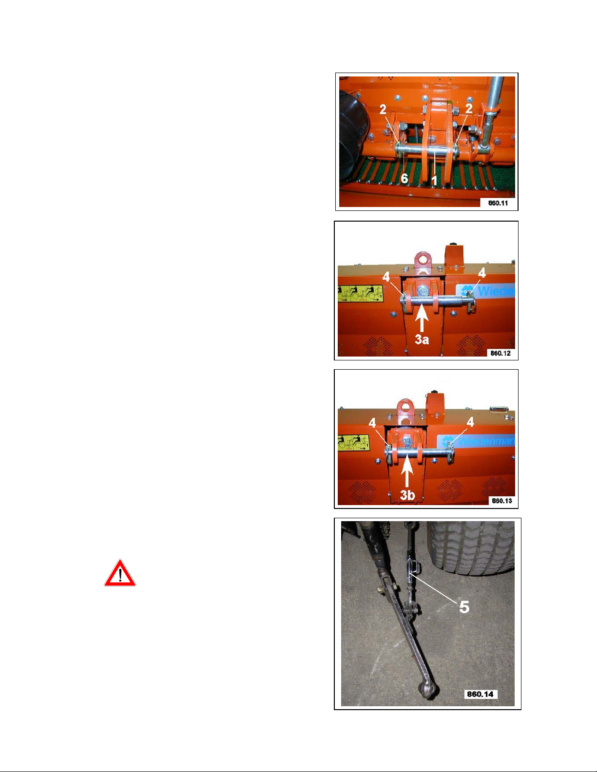
Mounting steps:
1. Mount the lower guide rod by:
inserting the bolt(1) and
locking it with the pin(2).
2. Mount the upper link. To do
so: depending on the tractor,
insert the bolt for category 1
with diameter (3a) and fix it
with the cotter key (4).
Or, for pegging with Cat. 2,
use diameter 3b.
3. Tighten the tension jack(5) of
the stabilizing chain.
4. Adapt the universal shaft
(refer to Chapter 4.4.).
5. Mount the PTO shaft by:
pushing in the slide pin of
the PTO shaft, slipping on the
PTO shaft, secure the PTO
shaft protector against
rotating with the shaft.
CAUTION DANGER !
Check for correct connection
before starting operation.
All information, illustrations and specifications in this manueal arw based on the latest information
available at the time of publication. The right is reserved to make changes at any time without notice.
19
 Loading...