

Wiedenmann Super 600 Translation Of Original Operating Instructions

Translation of original
operating instructions
Lawn Maintenance
Machine
Super 600
275.001
From machine ID no. :
10102750005142001
Version :
May 2014
275 99 09
2
All information, illustrations and specifications in this manual are based on the latest information
available at the time of publication. We reserve the right to make changes at any time without notice.
3
All information, illustrations and specifications in this manual are based on the latest information
available at the time of publication. We reserve the right to make changes at any time without notice.

4
Introduction
PLEASE READ THESE OPERATION INSTRUCTIONS CAREFULLY in order to familiarize
yourself the correct method of operation and maintenance and in order to avoid personal
injuries or damage to the machine.
This manual and safety decals on your machine may also be available in other languages
(see your dealer to order).
THIS MANUAL SHOULD BE CONSIDERED a permanent part of your machine and should
remain with the machine when you sell it.
MEASUREMENTS in this manual are given in both metric and customary U.S. unit equivalents.
Only use suitable parts and screws. Metric and inch fasteners may require a specific metric
or inch wrench.
RIGHT-HAND AND LEFT-HAND sides refer to the direction of travel when going forward.
WRITE PRODUCT IDENTIFICATION NUMBERS (P.I.N.) in the Specification or Identification
Numbers section. Please ensure that all numbers are correctly recorded. to help in tracing
the machine should it be stolen. Your dealer also requires this number when you order spare
parts. File the identification numbers in a secure place away from the machine.
BEFORE DELIVERING THIS MACHINE, your dealer performed a pre-delivery inspection to
ensure best performance.
THE LAWN MAINTENANCE MACHINE SUPER 600 IS SOLELY intended for conventional
maintenance of lawns (INTENDED USE).
This includes following tasks:
Gathering and collecting grass debris, leaves and twigs
Mowing lawns, parks, recreational areas, golf courses, extensively cultivated areas and eco-
meadows using the multifunction head
Verticutting golf courses and sports fields with different line distances using the multifunction
head
Use in any other way is considered contrary to the intended use. The manufacturer accepts
no liability for damage or injury resulting from this misuse, and these risks must be borne
solely by the user. Using the equipment in accordance with the specifications also includes
observance of the operating and maintenance conditions as specified by the manufacturer.
PREDICTABLE MISUSE AND ABUSE.Persons and objects must not be transported with the
machine attached.
THIS MACHINE SHOULD BE OPERATED, serviced and repaired only by persons familiar with
all its particular characteristics and acquainted with the relevant safety requirements
(accident prevention). The accident prevention regulations, all other generally recognized
regulations on occupational health and safety, and the road traffic regulations must be
observed at all times. Any unauthorized modifications carried out on this machine will relieve
the manufacturer of all liability for any resulting damage or injury.
NOTE THE INSTRUCTIONS
for driving on public roads:
"This machine is not suitable for travel on Highways or public roads. It requires additional
equipment for this (lighting kit, warning signs for slow vehicles/SMV sign, reflectors). Please
contact us if you wish to purchase this optional equipment “
available at the time of publication. We reserve the right to make changes at any time without notice.
All information, illustrations and specifications in this manual are based on the latest information

5
C O N T E N T S Page
* * * * * * * * * * * * * * * * * * * * * * * * * * * * * * * * * * * * * * * * * * * * * * * * * * *
1.0. Safety measures........................................ 7&17
1.1. Safety decals................................... 12&14
1.2. Notes on safety................................. 15
1.3. Safety features................................. 16&17
2.0. Transport.............................................. 18&21
2.1. General information............................. 18
2.2. Transporting of the Super 600................... 19&21
3.0. Assembly............................................... 22&30
3.1. General information............................. 22
3.2. Attaching drawbar............................... 22
3.3. Mounting the catcher............................ 23&24
3.4. Electrical connection to the battery............ 25
3.5. Connection of control panel..................... 26
3.6. Installing optional anti-scalp rollers.......... 27
3.7. Installing optional golf-course kit............. 28&29
3.8. Installing optional super contour kit........... 29&30
4.0. Attaching to a tractor................................. 31&33
4.1. General information............................. 32
4.2. Adjusting the drawbar........................... 32
4.3. Connecting the hydraulics....................... 32
4.4. Adjusting the PTO-shaft......................... 33
5.0. Detaching from the tractor............................. 34
5.1. General information............................. 34
5.2. Detaching....................................... 34
6.0. Before initial operation............................... 35&38
6.1. General information............................. 35
6.2. Setting the working height...................... 36
6.3. Setting the protection roller................... 36
6.4. Description of the functions
of the control panel............................ 37
6.5. Description of operation of tine sets........... 38
7.0. Operation.............................................. 39&46
7.1. General information............................. 39
7.2. Transport....................................... 39
7.3. Start-up........................................ 40
7.4. Empty hopper.................................... 41&43
7.5. Cleaning the blow-out openings.................. 44
7.6. Faults and remedies............................. 45&46
All information, illustrations and specifications in this manual are based on the latest information
available at the time of publication. We reserve the right to make changes at any time without notice.

6
C O N T E N T S Page
* * * * * * * * * * * * * * * * * * * * * * * * * * * * * * * * * * * * * * * * * * * * * * * * * * *
8.0. Maintenance............................................ 47&67
8.1. General information............................. 47
8.2. Lubricating greases............................. 48
8.3. Maintenance table............................... 48&50
8.4. Removing the drive protection................... 51&53
8.5. Clean channel................................... 54
8.6. Lubricating points.............................. 55
8.7. Gearbox......................................... 55
8.8. Replacing ribbed V-belt......................... 56&57
8.9. Hydraulic system................................ 58
8.10. Hydraulic connection diagram.................... 59
8.11. Tool change at multi-cultivation rail........... 60&61
8.12. Tool division................................... 62&65
8.13. Wheels and tires................................ 66
8.14. Disassembly/Disposal............................ 67
8.15. Unauthorized conversion and
Spare part manufacture.......................... 67
9.0. Additional equipment................................... 68&69
9.1. Equipment supplied.............................. 68
9.2. Optional equipment.............................. 68&69
10.0. Technical specifications............................... 70&73
10.1. Technical data.................................. 70&71
10.2. Torque values for metric screws and bolts....... 72
10.3. Chassis number.................................. 73
All information, illustrations and specifications in this manual are based on the latest information
available at the time of publication. We reserve the right to make changes at any time without notice.
7
1.0. Safety Measures
This is the safety alert symbol. When
you see this symbol on your machine
or in this manual, be aware of the
potential for personal injury.
Please observe all safety instructions
and the general accident prevention
regulations.
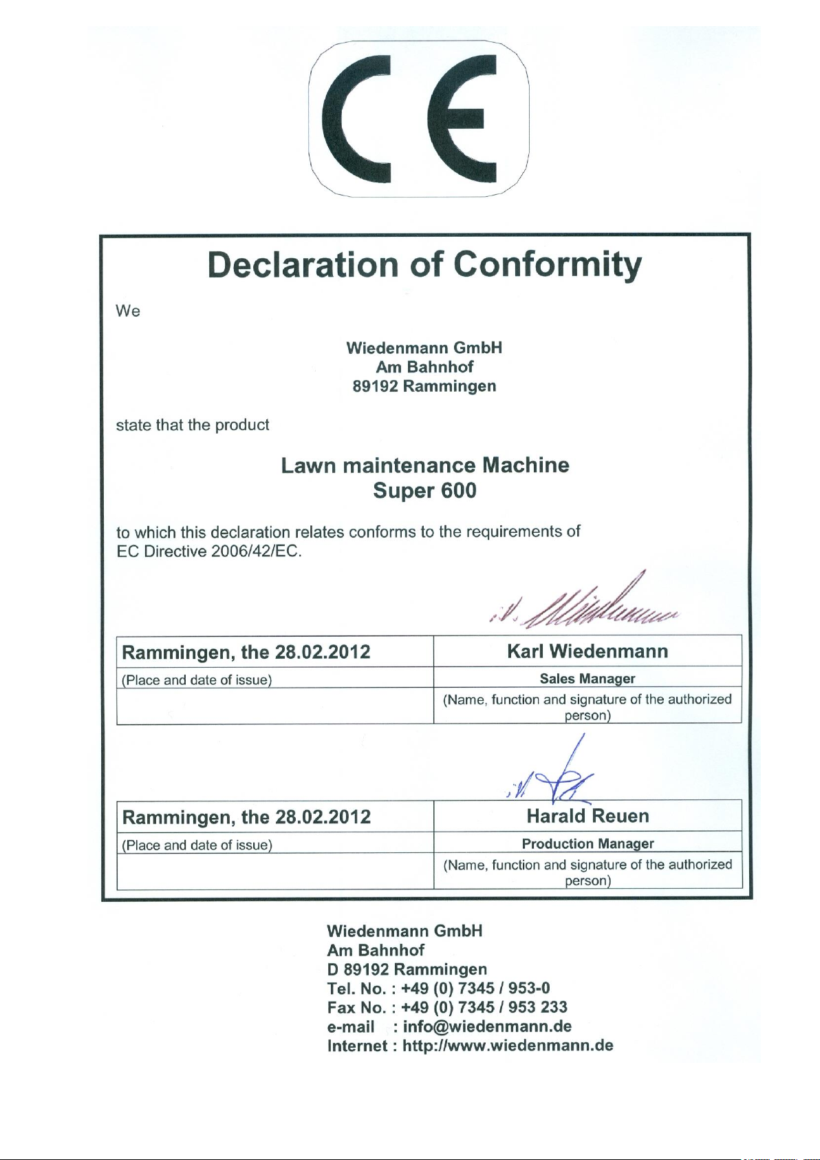
Carefully read all safety messages in
this manual and warning signs on your
machine. Keep warning signs in good
condition. Replace missing or
damaged warning signs. Make sure
that new equipment, components and
replacement parts include the current
warning signs. Replacement warning
signs are available from your dealer.
Learn how to operate the machine
and use the controls properly. Do not
let anyone operate without instruction.
Keep your machine in proper working
condition. Unauthorized modifications
to the machine may impair the
function and/or safety and affect
machine life.
If you do not understand any part of
this manual and need assistance,
contact your dealer.
RECOGNIZE SAFETY INFORMATION
FOLLOW SAFETY INSTRUCTIONS
All information, illustrations and specifications in this manual are based on the latest information
available at the time of publication. We reserve the right to make changes at any time without notice.

8
1.0. Safety Measures
Always observe local road traffic
regulations when using public roads.
Wear tight-fitting clothing and appropriate
protective equipment when working with
the machine.
Prolonged exposure to loud noise can
cause impairment or loss of hearing.
Wear a suitable hearing protective device
such as earplugs to protect against
objectionable or uncomfortably loud
noises.
Operating equipment safely requires the
full attention of the operator.
Do not wear radio or music headphones
while operating the machine.
Keep guards and shields in place all the
times. Ensure that they are in good
condition and installed correctly.
Always disengage the drive components,
turn off engine and remove key before
removing any guards or shields.
Keep hands, feet and clothing away from
moving parts.
OBSERVING ROAD TRAFFIC REGULATIONS
WEAR PROTECTIVE CLOTHING
GUARD AND SHIELDS
All information, illustrations and specifications in this manual are based on the latest information
available at the time of publication. We reserve the right to make changes at any time without notice.

9
1.0. Safety Measures
Inattentiveness in the area of rotating
drive shafts can have serious, or even
fatal, consequences.
Keep all drive shaft guards in place at all
times. Make sure rotating shields can turn
freely. Wear close fitting clothing. Stop
the engine and make sure PTO shaft is
stopped before making adjustments,
connections, or cleaning out PTO-driven
equipment.
High-pressure fluids which leak under
high pressure can penetrate the skin and
cause serious injury.
For this reason, always depressurize the
system before disconnecting lines.
Tighten all connections before applying
pressure.
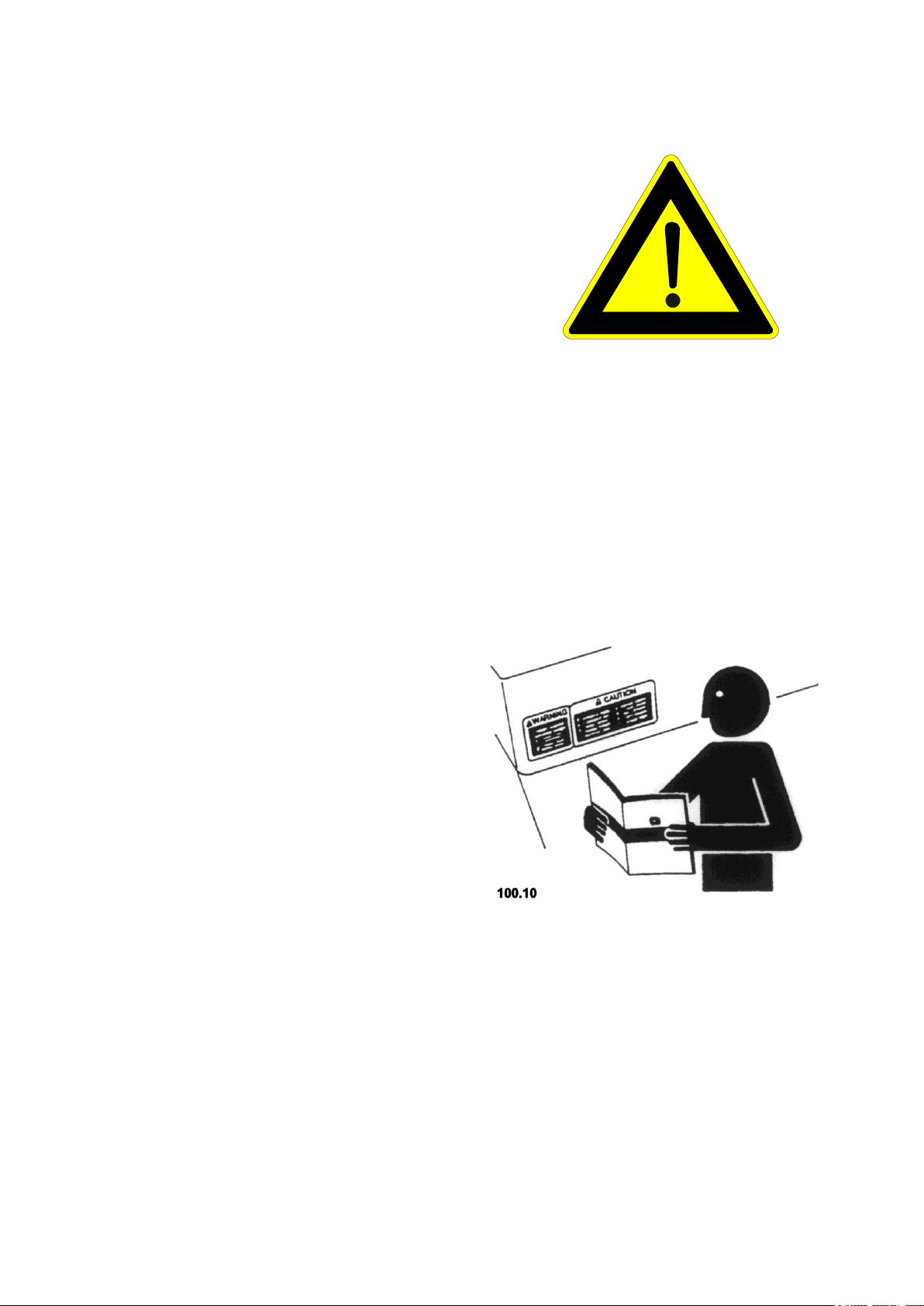
Hydraulic oil escaping from a small leak is
virtually invisible, therefore search for
leaks with a piece of cardboard. Protect
hands and body from high pressure
fluids.
If an accident occurs, see a doctor
immediately. Any fluid injected into the
skin must be surgically removed within a
few hours or gangrene may result.
Doctors unfamiliar with this type of injury
should check a reliable medical
reference.
STAY CLEAR OF ROTATING DRIVE SHAFTS
Avoid high-pressure fluids
All information, illustrations and specifications in this manual are based on the latest information
available at the time of publication. We reserve the right to make changes at any time without notice.
10
1.0. Safety Measures
Avoid collisions with other road users.
Slow moving tractors with attachments or
towed equipment and machines are a
particular hazard on public roads.
Frequently check for traffic from the rear,
especially in turns, Use hand signals or
turn signal lights for safe operation in
traffic. Use headlights, flashing warning
lights, and turn signals day and night.
Follow local regulations for equipment
lighting and marking. Always keep the
safety devices in good condition. Replace
or repair lighting and marking that has
been damaged or lost. An implement
safety lighting kit is available from your
dealer.
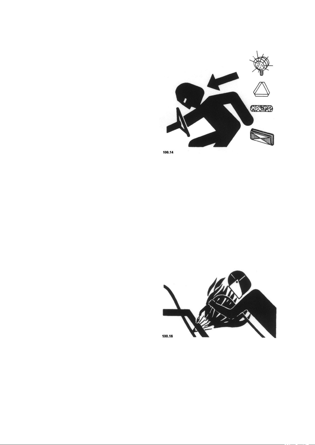
Highly flammable liquid mist can be
caused by heat development near
pressure lines. resulting in severe burns
to yourself and bystanders. Do not heat
by welding, soldering, or use a welding
torch near pressurized fluid lines or other
flammable materials. Pressurized lines
can be accidentally cut if heat goes
beyond the immediate flame area.
USE SAFETY LIGHTS AND DEVICES
AVOIDING HEAT DEVELOPMENT IN
THE AREA OF PRESSURE LINES
All information, illustrations and specifications in this manual are based on the latest information
available at the time of publication. We reserve the right to make changes at any time without notice.

11
1.0. Safety Measures
Welding must be conducted only by
persons with appropriate qualifications.
Avoid potentially toxic fumes and dust.
Hazardous fumes can be generated when
paint is heated by welding, soldering, or
using a torch.
Do all work outside or in a well ventilated
area. Dispose of paint and solvent
properly.
Remove paint before welding or heating:
If you sand paint, avoid breathing the
dust. Wear an approved respirator.
If you use solvent or paint stripper,
clean with soap and water before
welding. Remove solvent or paint
stripper containers and other
flammable material from area. Allow
fumes to disperse at least 15 minutes
before welding or heating.
Remove paint before welding or heating
All information, illustrations and specifications in this manual are based on the latest information
available at the time of publication. We reserve the right to make changes at any time without notice.
12
1.1. Safety Decals
Pictorial warning signs
Warning signs are attached to
several important places on this
machine to indicate potential
danger. The hazard is identified
by an exclamation point in a
warning triangle. An adjacent
symbol shows information on how
to avoid personal injury. These
safety signs, their placement on
the machine and a brief
explanatory text are shown below.
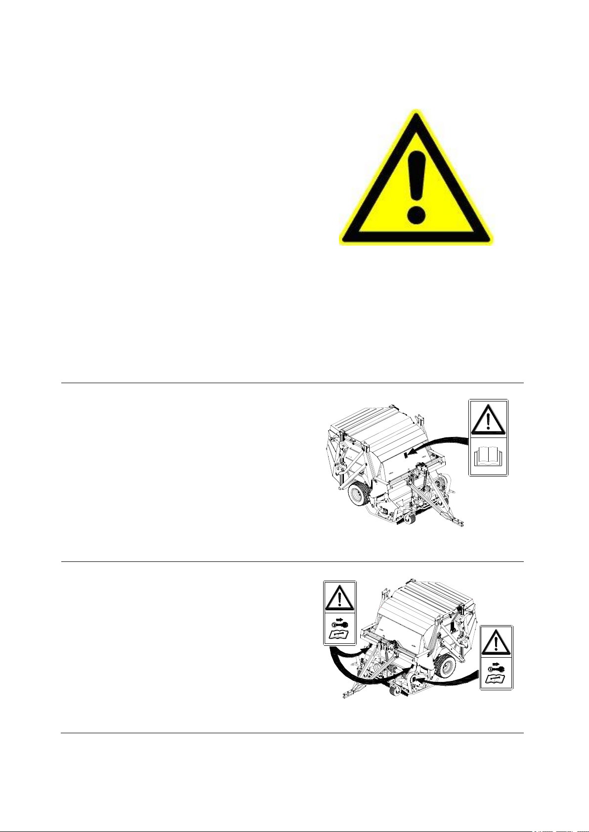
Operating Instructions
These Operating Instructions
contain important information on
the safe operation of this
machine. Carefully observe all
safety rules to avoid accidents.
275.01
Service
Before starting maintenance and
repair work, shut down the engine
and remove the ignition key.
275.02
1.0. Safety Measures
All information, illustrations and specifications in this manual are based on the latest information
available at the time of publication. We reserve the right to make changes at any time without notice.
13
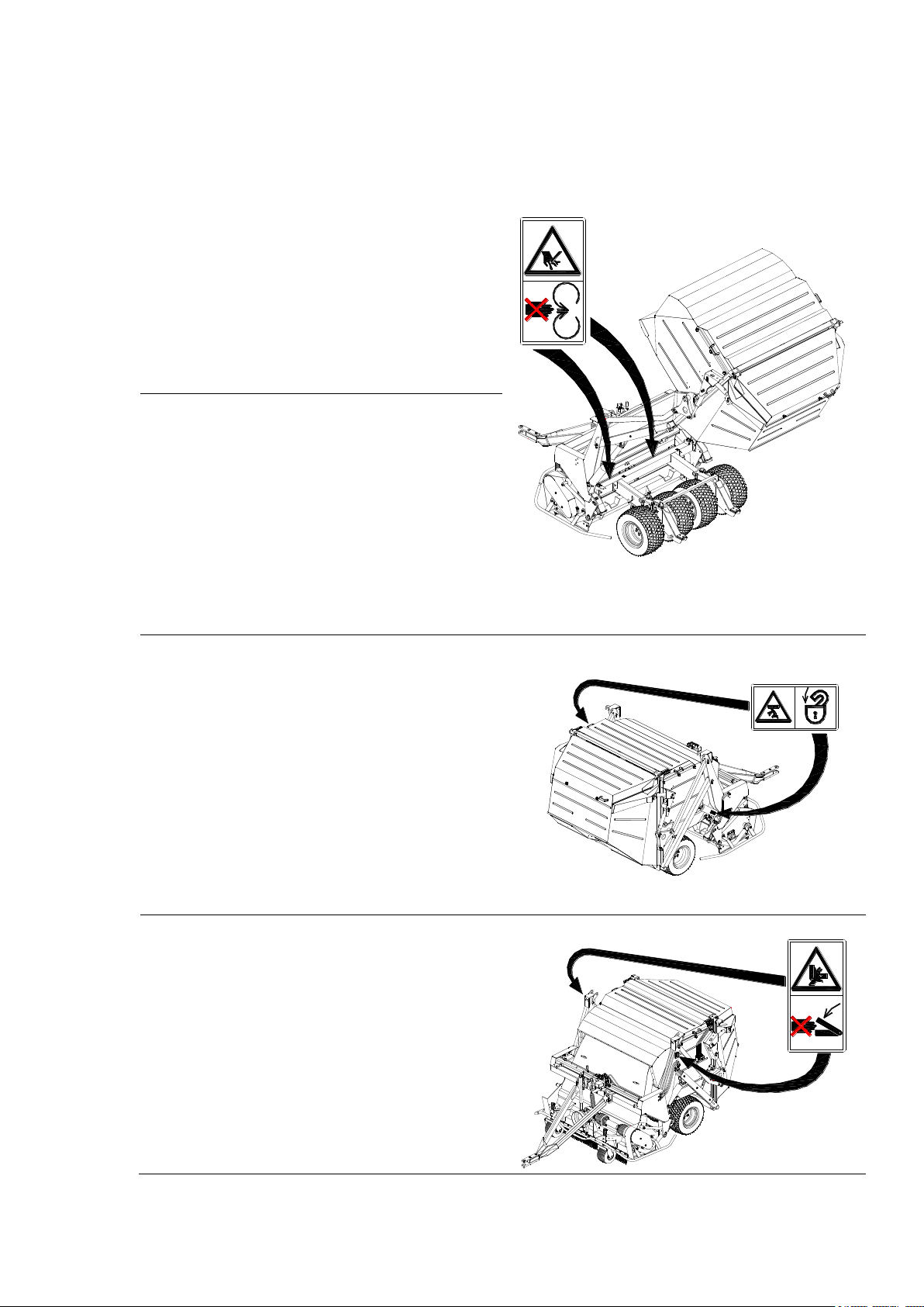
1.1. Safety Decals
Set of tines
Never touch moving parts of
the machine. Wait until they
have come to a complete
standstill.
275.03
Tools for the multifunction head
Never operate the
multifunction head when the
container is elevated. There
is danger of injury from the
spinning tool drum and from
parts flung out of it.
Hydraulic system for the elevated
emptying unit
Close the safety valve on the
hydraulic cylinder before
nearing the elevated
container. The closed safety
valve prevents the elevated
container from unintended
lowering.
275.04
Raising hopper
Never reach into areas where
there is a danger of crushing
while parts could still be
moving.
275.05
1.0. Safety Measures
All information, illustrations and specifications in this manual are based on the latest information
available at the time of publication. We reserve the right to make changes at any time without notice.
14
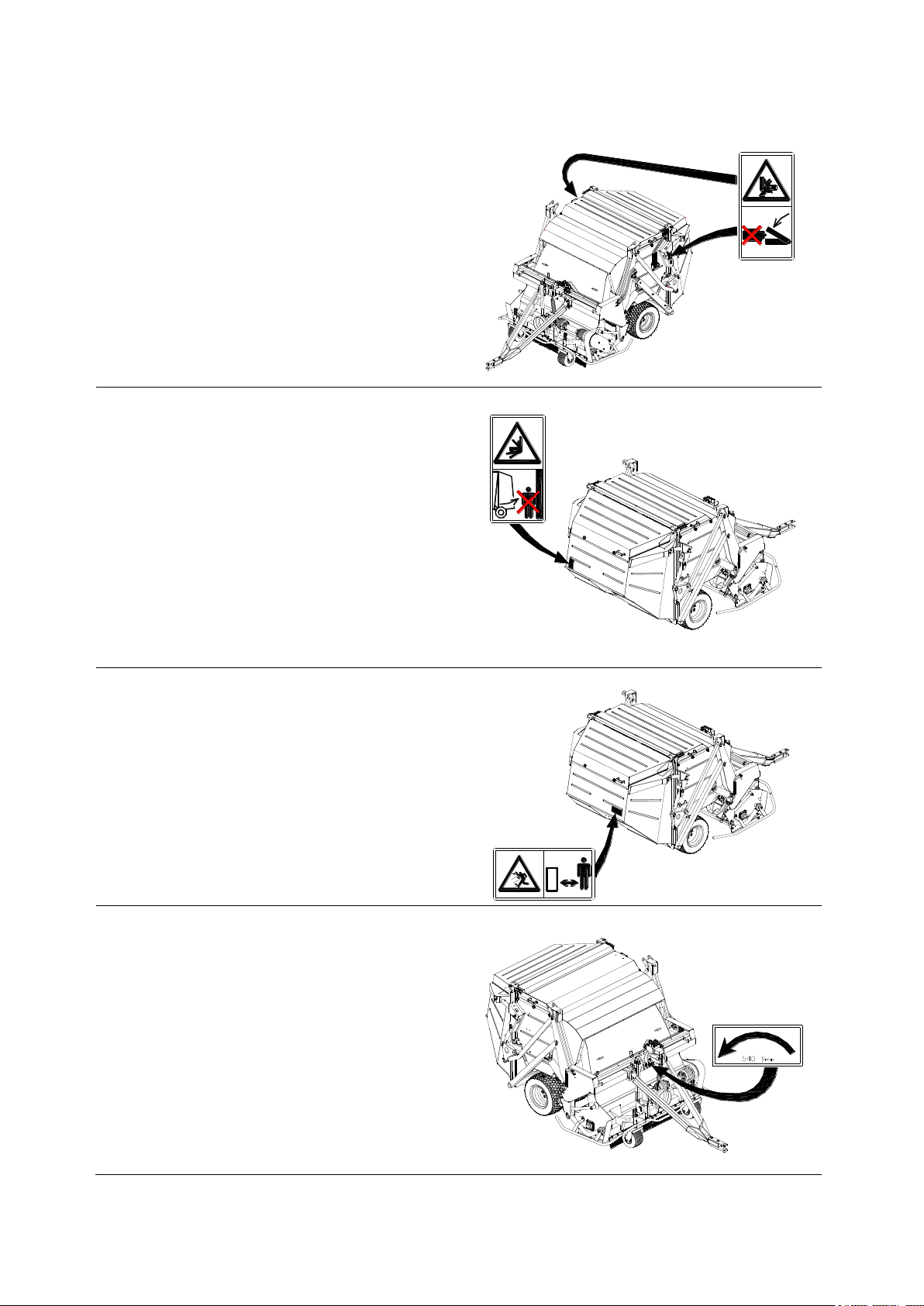
1.1. Safety Decals
Trap opening and emptying
Never reach into areas where
there is a danger of crushing
while parts could still be
moving.
275.07
Hopper flap opening
When the tractor engine is
running keep clear of the
swivel area of the safety
catch.
275.08
Screen and service flap
No persons are permitted in
front of the screen at the
back of the machine when the
Super 600 is running. There is
a risk of injury by ejected
objects or flying objects.
275.09
Universal joint drive
Information sign showing
direction of rotation and
maximum drive speed
275.60
1.0. Safety Measures
All information, illustrations and specifications in this manual are based on the latest information
available at the time of publication. We reserve the right to make changes at any time without notice.

15
1.2. Safety instructions
1.0. Safety Measures
Only persons who are
qualified and instructed on
the operation of the machine
may operate the machine.
Observe the generally
applicable safety and
accident prevention
regulations as well as the
notes in these operating
instructions!
Familiarize yourself with all
equipment and operating
elements and their functions
before starting work. Ensure
that all protective equipment
has been properly installed.
It is too late to do this
when you have started work!
In the working area, the user
is responsible for the safety
of other persons.
tractor must be steerable.
The driving and operating
properties of the tractor may
be influenced by the
attachment of the Super 600!
Always adapt your driving
style to match the terrain
and ground conditions.
Special care should be taken
when working and turning on a
slope.
Switch the P.T.O. drive of
the tractor off before
elevating the container.
Standing under the elevated
container without a safeguard
is forbidden. Always close
the safety valve on the
hydraulic cylinder.
Observe the applicable
regulations when using public
roads!
Check the immediate
surroundings before driving
(children!)!
Ensure that your visibility
is not impaired!
Keep all persons clear of the
danger zone of the machine!
Only attach the machine when
the engine is at a standstill
and the P.T.O. drive is
switched off.
Only use the cardan shaft
allocated to the machine.
Observe the maximum
permissible trailer and
drawbar load of the tractor.
Ensure that the front axle
has a sufficient load. The
The container may only be
elevated when the Super 600
is attached to a tractor.
Otherwise the Super 600 may
tip over.
Switch the machine and the
motor of the tractor off and
remove the ignition key
before carrying out
maintenance.
All safety devices must be
assembled before initial
operation of the Super 600.
All information, illustrations and specifications in this manual are based on the latest information
available at the time of publication. We reserve the right to make changes at any time without notice.
16
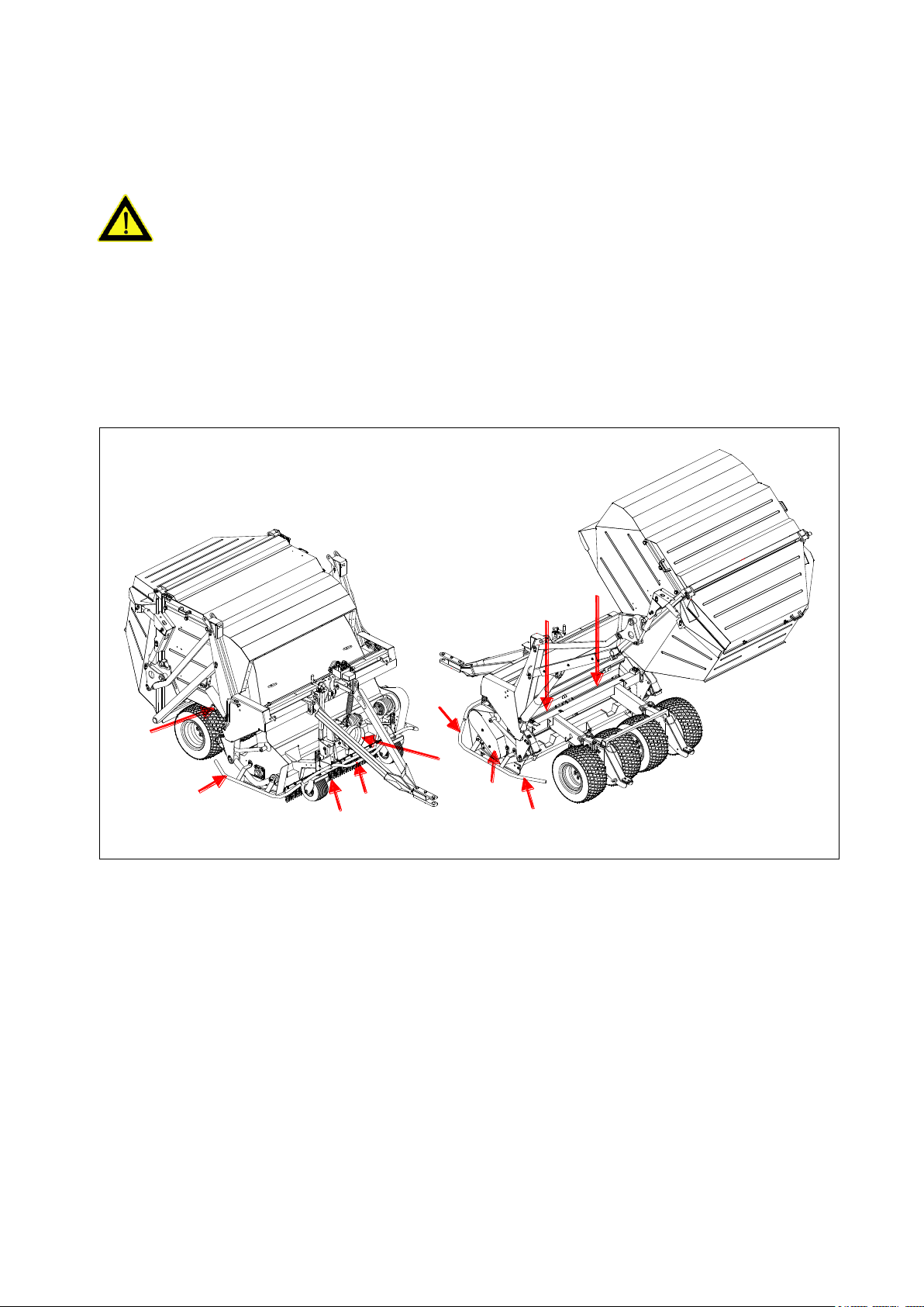
1.3. Safety Equipment
B
C
A
B
D
B
F
275.10
B
E
E
1.3.1 at the machine
ATTENTION DANGER!
1.0. Safety Measures
Never operate the Super 600
without safety devices.
Otherwise you expose yourself
and others to great danger.
The positions of the safety
equipment on your machine:
Serious injury by moving
parts can result.
A Protection device for
cardan shaft connection
(can only be undone with
tools)
B hoop guard center, left
and right (permanently
attached as spacers)
C Safety vales on both
telescope cylinders
(prevent unintentional
lowering of the raised
container)
D chain curtain or front
roller
E Flaps for tool change at
the multi-cultivation rail
(can only be undone with
tools)
F guard for belt drive on
multi-maintenance head
(removable with tools only)
All information, illustrations and specifications in this manual are based on the latest information
available at the time of publication. We reserve the right to make changes at any time without notice.
17
1.3. Safety Equipment
1.3.2. at the remote control
ATTENTION DANGER!
Lifting multimaintenance head.
Otherwise you expose
yourself and others to
extreme danger.
Serious injury by moving
parts can result.
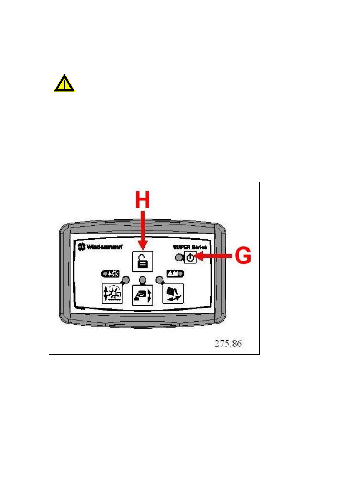
Positions of keys:
1.0. Safety Measures
G ON/OFF key – all valves are closed
when the control panel is switched off.
H The mode can only be changed after
pressing the unlock key.
All information, illustrations and specifications in this manual are based on the latest information
available at the time of publication. We reserve the right to make changes at any time without notice.

18
2.1. General information
ATTENTION DANGER!
The turf care machine is
delivered fastened to a
shipping frame.
Only use a forklift with
sufficient load-carrying
capacity.
Keep well clear of hoisted
loads. If the load falls it
may cause fatal injuries.
Improper transport and assembly
of the turf care machine may:
2.0. Transport
injury to persons,
damage to property.
Take particular care of the
direction of approach when
lifting with the shipping
frame.
We will not accept any
liability for damage resulting
from improper handling.
ATTENTION DANGER!
Be careful when cutting through
the tension straps. There is a
risk of being injured when the
straps are cut.
All information, illustrations and specifications in this manual are based on the latest information
available at the time of publication. We reserve the right to make changes at any time without notice.
19
2.0. Transport
2.2. Transporting the Super 600
2.2.1. Transport Using a Forklift
If the turf care machine is
still fastened to the shipping
frame:
move the forks into the
shipping frame, (note
direction of approach)
carefully raise the shipping
frame,
unload the turf care machine
from the shipping unit if it
is balanced,
Remove the upper and side
parts of the shipping frame,
cut through the tension straps,
lift the turf care machine
off the shipping frame.
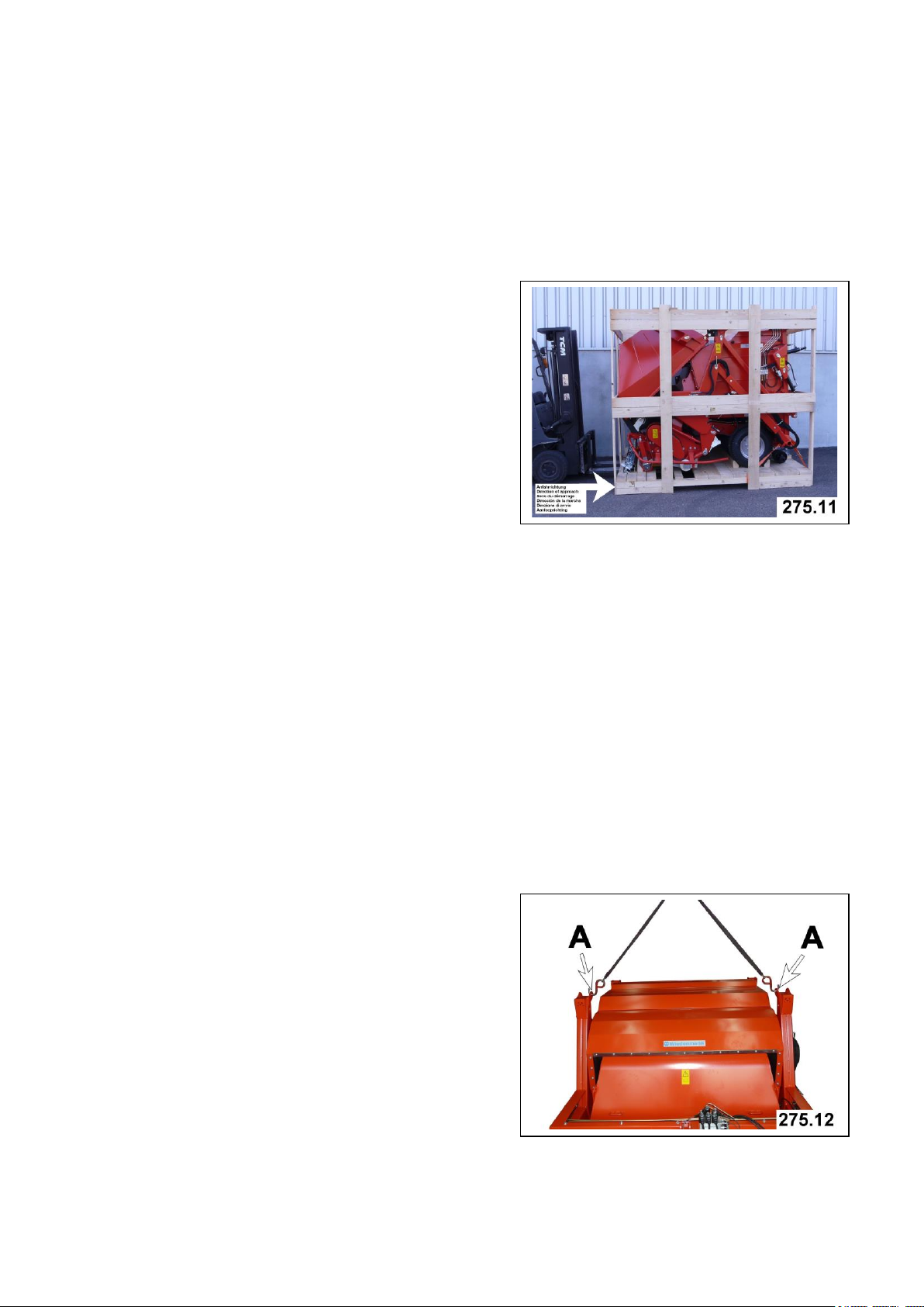
2.2.2. Transport Using a Crane
There are three points on the
turf care machine for lifting
it with a crane.
Point A: 2 items on the frame
All information, illustrations and specifications in this manual are based on the latest information
available at the time of publication. We reserve the right to make changes at any time without notice.
20
2.0. Transport
2.2. Transporting the Super 600
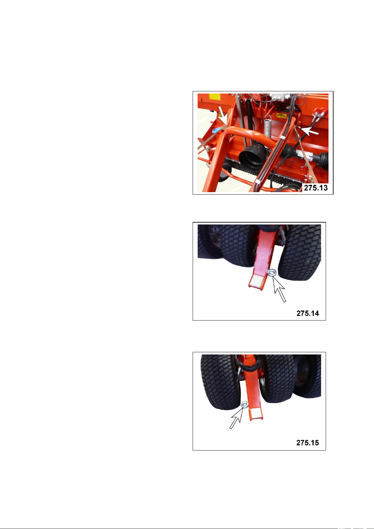
2.2.3. Hitching point for transport on a
trailer
Point C: 2 items on the drawbar
(left arrow)
or
a hole in the clips on
the frame (right
arrow)
depending on the
lifting material
Point D: 1 item on the right on
the moving gear frame
Point E: 1 item on the left on
the moving gear frame
All information, illustrations and specifications in this manual are based on the latest information
available at the time of publication. We reserve the right to make changes at any time without notice.

21
2.0. Transport
2.2. Transporting the Super 600
2.2.4. Shipping frame
The catcher (A) and drawbar (B)
are not mounted for shipping.
The catcher (A) is fastened to
the front of the machine at the
top with special parts.
The drawbar (B) is fastened to
the rear on the shipping frame
with special parts.
For description of mounting the
catcher see Section 3.3.
All information, illustrations and specifications in this manual are based on the latest information
available at the time of publication. We reserve the right to make changes at any time without notice.
22
3.1. General information
3.0. Assembly
ATTENTION DANGER!
Do this work only when the
machine is attached to the
tractor. The tractor must be
shut down and secured against
accidental starting.
Close the safety valves at
both telescope cylinders to
secure the container against
accidental lowering.
3.2. Attaching drawbar
Two persons are required to
attach the drawbar.
For this work, please use
your personal protective
equipment (PSA) such as:
gloves, goggles, ear
protectors.
Attachment must be carried
out on solid flat ground
only.
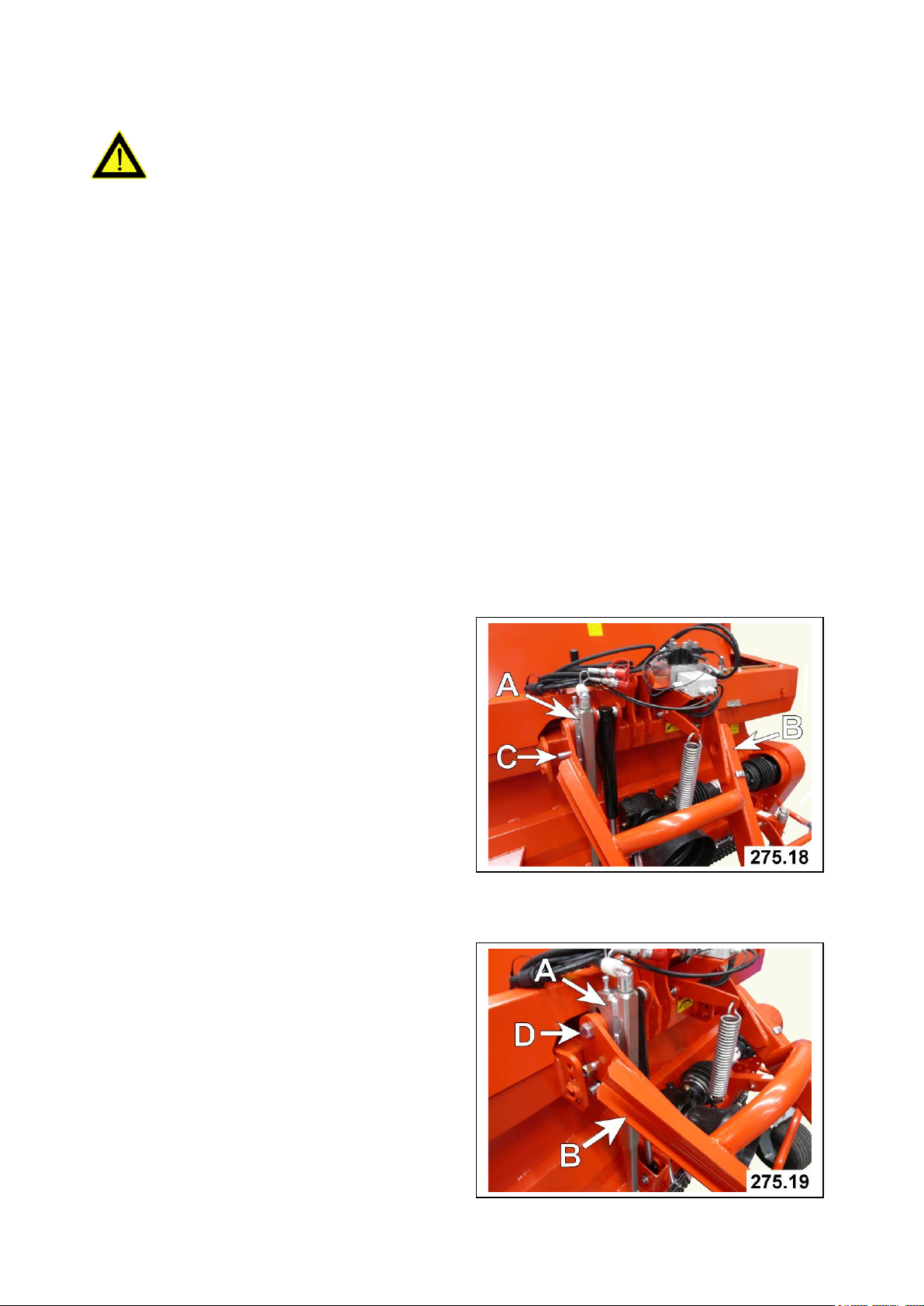
To ensure that support (A)
remains active, the bottom
fastening bolt must not be
removed.
Position the drawbar (B) at the
front on the fishplates.
Insert the bottom hexagon bolts
(C) from inside to outside at
the bottom holes of the drawbar
(B).
Screw the nuts on hand-tight.
Swivel drawbar (B) upwards and
insert hexagon bolts (D) from
outside to inside.
Screw on all hexagon nuts and
tighten them.
All information, illustrations and specifications in this manual are based on the latest information
available at the time of publication. We reserve the right to make changes at any time without notice.
 Loading...